US6033409A - Surgical drill with bit penetration control and breakthrough detection - Google Patents
Surgical drill with bit penetration control and breakthrough detection Download PDFInfo
- Publication number
- US6033409A US6033409A US09/297,391 US29739199A US6033409A US 6033409 A US6033409 A US 6033409A US 29739199 A US29739199 A US 29739199A US 6033409 A US6033409 A US 6033409A
- Authority
- US
- United States
- Prior art keywords
- support
- drill bit
- drill
- respect
- actuating unit
- Prior art date
- Legal status (The legal status is an assumption and is not a legal conclusion. Google has not performed a legal analysis and makes no representation as to the accuracy of the status listed.)
- Expired - Fee Related
Links
- 238000001514 detection method Methods 0.000 title claims abstract description 11
- 230000035515 penetration Effects 0.000 title description 9
- 238000006073 displacement reaction Methods 0.000 claims abstract description 28
- 238000005553 drilling Methods 0.000 claims abstract description 22
- 230000000284 resting effect Effects 0.000 claims abstract description 10
- 230000005540 biological transmission Effects 0.000 claims description 4
- 238000007789 sealing Methods 0.000 claims description 3
- 210000000988 bone and bone Anatomy 0.000 description 17
- 230000001054 cortical effect Effects 0.000 description 9
- 230000008878 coupling Effects 0.000 description 3
- 238000010168 coupling process Methods 0.000 description 3
- 238000005859 coupling reaction Methods 0.000 description 3
- 230000000149 penetrating effect Effects 0.000 description 2
- 210000001519 tissue Anatomy 0.000 description 2
- 238000004458 analytical method Methods 0.000 description 1
- 230000000903 blocking effect Effects 0.000 description 1
- 238000006243 chemical reaction Methods 0.000 description 1
- 238000004140 cleaning Methods 0.000 description 1
- 238000010586 diagram Methods 0.000 description 1
- 238000012067 mathematical method Methods 0.000 description 1
- 238000005259 measurement Methods 0.000 description 1
- 230000007246 mechanism Effects 0.000 description 1
- 238000012829 orthopaedic surgery Methods 0.000 description 1
Images
Classifications
-
- A—HUMAN NECESSITIES
- A61—MEDICAL OR VETERINARY SCIENCE; HYGIENE
- A61B—DIAGNOSIS; SURGERY; IDENTIFICATION
- A61B17/00—Surgical instruments, devices or methods, e.g. tourniquets
- A61B17/16—Bone cutting, breaking or removal means other than saws, e.g. Osteoclasts; Drills or chisels for bones; Trepans
- A61B17/1613—Component parts
- A61B17/1622—Drill handpieces
-
- B—PERFORMING OPERATIONS; TRANSPORTING
- B23—MACHINE TOOLS; METAL-WORKING NOT OTHERWISE PROVIDED FOR
- B23Q—DETAILS, COMPONENTS, OR ACCESSORIES FOR MACHINE TOOLS, e.g. ARRANGEMENTS FOR COPYING OR CONTROLLING; MACHINE TOOLS IN GENERAL CHARACTERISED BY THE CONSTRUCTION OF PARTICULAR DETAILS OR COMPONENTS; COMBINATIONS OR ASSOCIATIONS OF METAL-WORKING MACHINES, NOT DIRECTED TO A PARTICULAR RESULT
- B23Q5/00—Driving or feeding mechanisms; Control arrangements therefor
- B23Q5/22—Feeding members carrying tools or work
- B23Q5/32—Feeding working-spindles
-
- B—PERFORMING OPERATIONS; TRANSPORTING
- B25—HAND TOOLS; PORTABLE POWER-DRIVEN TOOLS; MANIPULATORS
- B25F—COMBINATION OR MULTI-PURPOSE TOOLS NOT OTHERWISE PROVIDED FOR; DETAILS OR COMPONENTS OF PORTABLE POWER-DRIVEN TOOLS NOT PARTICULARLY RELATED TO THE OPERATIONS PERFORMED AND NOT OTHERWISE PROVIDED FOR
- B25F5/00—Details or components of portable power-driven tools not particularly related to the operations performed and not otherwise provided for
- B25F5/003—Stops for limiting depth in rotary hand tools
-
- A—HUMAN NECESSITIES
- A61—MEDICAL OR VETERINARY SCIENCE; HYGIENE
- A61B—DIAGNOSIS; SURGERY; IDENTIFICATION
- A61B90/00—Instruments, implements or accessories specially adapted for surgery or diagnosis and not covered by any of the groups A61B1/00 - A61B50/00, e.g. for luxation treatment or for protecting wound edges
- A61B90/03—Automatic limiting or abutting means, e.g. for safety
- A61B2090/033—Abutting means, stops, e.g. abutting on tissue or skin
Definitions
- the present invention generally relates to the field of apparatus for orthopaedic surgery and, more precisely, it relates to a surgical drill and actuating unit with drill bit penetration control and breakthrough detection.
- a surgical drill is often used for osteosynthesis operations and is guided manually by the surgeon, who carries out the drilling step according to his/her experience.
- the surgeon when transversally drilling a bone, the surgeon often has either to bore both the two cortical bone walls, making a substantially through hole, or has to bore only one wall, either passing through or not passing through the trabecular or medullar bone.
- it is difficult to carry out a correct drilling step without an automatic control of the drill bit displacement and of the drill bit piercing force and this depends totally on the surgeon's skill, who is also aware that to bore more than necessary could be useless and harmful for the patient.
- the drilling step has often to be carried out uncomfortably, according to the drilling direction with respect to the patient, and the more it is difficult and the more the risk of error rises.
- the surgeon in any case, however skill, cannot reduce beyond certain limits the drill bit displacement error.
- U.S. Pat. No. 3,897,166 describes a drill which can also be used in medical work such as bone drilling.
- the drill support comprises a pressure foot at its forward end to contact a work piece to be drilled.
- the support carries out the feed control of the pressure foot by means of a slide operated by the drive shaft of the drill. Therefore, pressure applied to the drill motor does not cause directly penetration of the work piece, such penetration being proportional to the speed of the drive shaft with respect to the pressure foot. Since the bit cannot advance freely, it cannot surge or jam when it breaks through the rear of the work piece.
- U.S. Pat. No. 3,897,166 does not provide means for preventing the drill bit from breaking through a cortical wall of a bone, thus causing serious damages to the patient. In fact, the drill bit displacement is continuously fed unless the operator decides to stop the drive shaft rotation.
- the surgical drill and by the actuating unit according to the invention comprising a first support for a rotating head holding the drill bit, wherein means for preventing a wall of the body from being broken through by said drill bit are provided.
- the means for preventing comprise in combination:
- a second support suitable for resting directly upon the patient and translating with respect to the first support parallelly to the drill bit
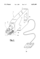
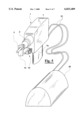
- FIG. 1 shows a perspective view of a surgical drill according to the present invention
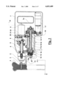
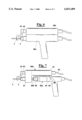
- FIG. 2 is a cross sectional view by a longitudinal plane of the surgical drill of FIG. 1;
- FIG. 3 shows a cross sectional view according to arrows III--III of the drill of FIG. 2;
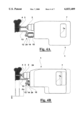
- FIGS. 4A and 4B show an elevational lateral view of the drill of FIGS. 1 and 2 in two operative positions;
- FIG. 5 shows a perspective view of a first different embodiment of the surgical drill of FIG. 1;
- FIG. 6 shows a perspective view of a second different embodiment of the surgical drill of FIG. 1;
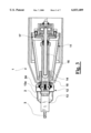
- FIG. 7 shows a perspective view of a third different embodiment of the surgical drill of FIG. 1;
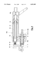
- FIG. 8 shows a cross sectional view of an actuating unit of the embodiment of FIG. 7.
- a surgical drill 1 comprises a rotating head 2 having a drill bit 3 suitable to bore a body 4 (FIG. 2), such as a body bone, during a surgical operation of osteosynthesis.
- Head 2 (FIGS. 2 and 3) is pivotally connected by means of a shaft 5 to a housing 6 mounted in a casing 7 having a handgrip 7a to hold the drill 1.
- housing 6 engages also a gearing 8 which rotates shaft 5 operated by a motor 9.
- actuating unit 10 suitable to guide drill bit 3 with respect to body 4. More precisely, actuating unit 10 comprises a first support 11, integral to housing 6, and a second support 12 capable of resting on body 4. Second support 12 comprises a rest element 13 and a nut screw element 14 which can slide in a bushing 15 integral to casing 7 and to first support 11. With nut screw element 14 engages a screw threaded shaft 16 pivotally connected to first support 11 and brought into rotation by a motor 17 via a gearing 18. A tooth 19 integral to nut screw element 14 guides the latter when translating since it engages with a groove 11a provided for in first support 11.
- First support 11 is integral to housing 6 by means of a rigid plate 20. More precisely, plate 20 carries motor 9 and mechanically connects first support 11 and housing 6 through gearing 8. Shaft 5 of head 2 does not drive any axial forces to housing 6 even if pivotally connected with the latter, but it loads all the forces acting on drill bit 3 onto plate 20 via a flexion detector 21 and a pin 22, parallel and eccentric to shaft 5. Flexion detector 21 comprises strain gauges which correlate the flexion caused by the axial force of shaft 5 with the force itself, due to the resistance which the drill bit 3 meets in the body 4 while penetrating.
- the drilling step that is the penetration of the rotating drill bit 3 through the body 4 is possible only when a relative movement between rest element 13 and drill bit 3 is carried out. More precisely, the surgeon, by means of actuating means, such as pedal means 23 (FIG. 1), starts the drill bit displacement with respect to second support 12 after having put the rest element 13 thereof over and then onto the exact point of the body 4 to bore. Drill bit 3, before that the drilling step starts, is arranged so that it does not protrude from rest element 13 outer surface, as shown in FIG. 4A and in FIG. 1 with dotted line.
- drill bit displacement is not caused any more by the pushing force acting on the drill, but is caused by a relative movement of the first support with respect to the second support, which rests upon the body itself.
- the pushing force of the surgeon is only necessary to assure that rest element 13 is always kept in still contact with body 4.
- Drill bit 3 displacement is advantageously controlled by an electronic unit not shown which analyses signals proportional to the force acting on drill bit 3 and discharged onto first support 11 through shaft 5, as detected by flexion sensor 21, or, equivalently, by a load cell of different kind.
- the measurement of the force in correlation with the drill bit displacement according to a programmable logic residing in the electronic unit, operates the automatic block of the drill in certain critical conditions, such as the breakthrough detection of a cortical bone wall, or the drill bit reaching the second cortical bone wall after having crossed the trabecular bone, as shown in FIG. 2 or in FIG. 4B.
- the rest element 13 can be pivoted with respect to second support 12 about a pin 13a and put in a position of minimum encumbrance, shown with a dotted line, with the result that drill 1 could be used as a common surgical drill, that is with displacement controlled only by the push of the surgeon, depending on the preference of the latter choosing between an use according to the invention or a traditional use.
- rest element 13 could be pivoted in minimum encumbrance position when the drill is not used, so that the sensor and the mechanisms of the two supports are not damaged.
- rest element 13 could be integral to second support 12, without possibility of being pivoted.
- Holdable casing 7 is preferably sealed, and it may comprise sealing means at the head 2 coupling with nut screw element 14.
- the latter which variably protrudes from drill 1, may have a bellows 24, as shown in FIGS. 4A and 4B, which protects it from dirty and simplifies cleaning.
- the whole drill 1 could be sterilised by autoclave like whichever surgical tool.
- a first different embodiment of drill 1 has a casing 7 of reduced encumbrance with respect to that of FIG. 1, thanks to a separated driving unit 30 and a protruding handgrip 7a.
- driving unit 30 comprises internally the same motors 9 and 17 of head 2 and of actuating unit 10 respectively.
- the drive transmission is carried out by means of cables 31, and is of known type in the field of the medical apparatus, such as like that used for dentistry drills, and therefore is non described further.
- a drill 40a can be separated from its actuating unit 40b.
- drill 40a can be used as a normal drill when separated, as well as it can be used according to the invention when associated to actuating unit 40b in the manner described above.
- Drill 40a has inside the load cells for detecting the force, whereas actuating unit 40b controls the displacement of rest element 43 and second support 42 with respect to first support, which is provided for inside its casing.
- an actuating unit 50b (FIG. 7) is designed to be associated to a commercial surgical drill 50a which has not force sensors like drill 40a has.
- actuating unit 50b has a casing 57 with a first support 51 for a shaft 55 to which a drill bit 3 can be connected at its end 55a which supports head 2.
- Shaft 55 has the other end 55b capable of being gripped by a chuck head 58 of drill 50a (as shown in FIG. 7) and comprises a load cell disc 61 detecting axial forces transmitted by drill bit 3 during the drilling step.
- a screw threaded bar 56 is provided for, engaging with a nut screw element 54 of a second support 52 having a rest element 53 at one end. Rest element 53 engages with nut screw element 54 by means of a dove tailed coupling (not visible in cross section) and a spring loaded ball 59, and can be disengaged in the direction of the arrow.
- Second support 52 is slidingly coupled to casing 57 by means of a bushing 65.
- End 56a of threaded bar 56 can engage with a transmission cable 62 (FIG. 1) connected to a driving unit not shown.
- Commercial drill 50a can be fastened to actuating unit 50b by coupling chuck 58 with end 55b and, at the same time, connecting brackets 64 to the drill by means of screws 66.
- FIGS. 7 and 8 is particularly advantageous, since it allows the use of a normal surgical drill, reducing the cost of the whole apparatus when such drill is already available. In addition, according to the invention, it has the same advantages of the other embodiments already described above.
- the logic used to correlate force and displacement is preferably a "fuzzy" logic, already known and implemented in various robot apparatus. Using this logic, or other known mathematical methods, it is possible to obtain an algorithm which describes the reaction to penetration of drill bit 3 in body 4, as a function of the force detected and to the drill bit displacement, and it is thus possible to control precisely the drilling phase.
- the control of the penetration of the drill bit in the body can be carried out with precision, with the possibility of blocking the drill bit displacement in the following critical cases:
- Drill bit displacement S which is equal to the actual drill bit displacement and opposite to the stroke of second support 12 with respect to first support 11, could be blocked automatically in the points of maximum variation of F with respect to S.
- the drill and the actuating unit thereof according to the invention succeed in achieving the above objects.
- a fixed support for the drill cannot be provided for, it is possible, by resting directly against the body to bore, to control directly the progress of the drill bit when penetrating the tissues, as well as to control with precision the drill bit displacement and the drilling force limiting them in occasion of critical points.
- This is possible thanks to the presence of the second support, which has the function both of rest and of reference for the drill.
Abstract
A surgical drill (1), comprising a rotating head (2) having a drill bit (3) suitable to bore a body (4) and support means (7) to which the head (2) is pivotally connected. An actuating unit (10) of the movement of the drill bit (3) with respect to the body to bore (4) is provided for, comprising a first support (11) comprising the head (2) and a second support (12), suitable for resting directly upon the body (4) and translating with respect to the first support (11) parallel to the drill bit (3). The movement between drill bit (3) and body (4) is caused by the relative movement between drill bit (3) and second support (12). Means (21) for the detection of the force acting on the drill bit and means for the control of the drill bit displacement in function of the drilling force are provided for. The drill, manually holdable, presents both a reference with respect to the patient body and allows a precise control of the drill bit displacement.
Description
1. Field of the invention
The present invention generally relates to the field of apparatus for orthopaedic surgery and, more precisely, it relates to a surgical drill and actuating unit with drill bit penetration control and breakthrough detection.
2. Description of the prior art
It is at present felt by surgeons the need of a drill having sensors which can control the drill bit penetration while making a bore in a tissue, in particular a bone wall.
In fact, a surgical drill is often used for osteosynthesis operations and is guided manually by the surgeon, who carries out the drilling step according to his/her experience. For example, when transversally drilling a bone, the surgeon often has either to bore both the two cortical bone walls, making a substantially through hole, or has to bore only one wall, either passing through or not passing through the trabecular or medullar bone. However, it is difficult to carry out a correct drilling step without an automatic control of the drill bit displacement and of the drill bit piercing force and this depends totally on the surgeon's skill, who is also aware that to bore more than necessary could be useless and harmful for the patient.
Moreover, the drilling step has often to be carried out uncomfortably, according to the drilling direction with respect to the patient, and the more it is difficult and the more the risk of error rises. The surgeon, in any case, however skill, cannot reduce beyond certain limits the drill bit displacement error.
On the other hand, even if an industrial drill can be mounted on a fixed support having mechanically adjustable displacement means, this solution cannot be used in the case of a surgical drill, since the parts to be bored, differently from what occurs in the industrial field, cannot be fixed to reliable reference surfaces.
U.S. Pat. No. 3,897,166 describes a drill which can also be used in medical work such as bone drilling. The drill support comprises a pressure foot at its forward end to contact a work piece to be drilled. The support carries out the feed control of the pressure foot by means of a slide operated by the drive shaft of the drill. Therefore, pressure applied to the drill motor does not cause directly penetration of the work piece, such penetration being proportional to the speed of the drive shaft with respect to the pressure foot. Since the bit cannot advance freely, it cannot surge or jam when it breaks through the rear of the work piece.
However, U.S. Pat. No. 3,897,166 does not provide means for preventing the drill bit from breaking through a cortical wall of a bone, thus causing serious damages to the patient. In fact, the drill bit displacement is continuously fed unless the operator decides to stop the drive shaft rotation.
It is, therefore, object of the present invention to provide a surgical drill which allows at the same time, even if handled manually:
to get a reference support on the patient and thus a more precise control of the drill bit penetration in the body to bore with respect to a drill of known art,
the control of the drilling force and provides a stop of the drill bit when the breakthrough is incipient. In alternative, it is object of the invention to provide an actuating unit, which can be associated to an already existing surgical drill, that allows the control of the drill bit displacement and of the drilling force with respect to the body to bore as well as provides a stop of the drill bit when the breakthrough is incipient.
These and other objects are achieved by the surgical drill and by the actuating unit according to the invention, comprising a first support for a rotating head holding the drill bit, wherein means for preventing a wall of the body from being broken through by said drill bit are provided. The means for preventing comprise in combination:
a second support, suitable for resting directly upon the patient and translating with respect to the first support parallelly to the drill bit,
means for detecting in the first support the force acting on the drill bit while drilling, and
means for controlling the displacement of the first support with respect to the second support and responsive to the means of detection of the force, whereby both a reliable guide of the drill bit and an automatic stop of the displacement of the drill bit in case of breakthrough condition are provided.
Further characteristics and advantages of the apparatus according to the present invention will become more apparent in the description which follows of some of its embodiments, given as an example and not limitative, with reference to the attached drawings in which:
FIG. 1 shows a perspective view of a surgical drill according to the present invention;
FIG. 2 is a cross sectional view by a longitudinal plane of the surgical drill of FIG. 1;
FIG. 3 shows a cross sectional view according to arrows III--III of the drill of FIG. 2;
FIGS. 4A and 4B show an elevational lateral view of the drill of FIGS. 1 and 2 in two operative positions;
FIG. 5 shows a perspective view of a first different embodiment of the surgical drill of FIG. 1;
FIG. 6 shows a perspective view of a second different embodiment of the surgical drill of FIG. 1;
FIG. 7 shows a perspective view of a third different embodiment of the surgical drill of FIG. 1;
FIG. 8 shows a cross sectional view of an actuating unit of the embodiment of FIG. 7.
With reference to FIGS. 1 to 3, a surgical drill 1 comprises a rotating head 2 having a drill bit 3 suitable to bore a body 4 (FIG. 2), such as a body bone, during a surgical operation of osteosynthesis. Head 2 (FIGS. 2 and 3) is pivotally connected by means of a shaft 5 to a housing 6 mounted in a casing 7 having a handgrip 7a to hold the drill 1. With housing 6 engages also a gearing 8 which rotates shaft 5 operated by a motor 9.
Always with reference to FIGS. 2 and 3, to casing 7 is connected also an actuating unit 10 suitable to guide drill bit 3 with respect to body 4. More precisely, actuating unit 10 comprises a first support 11, integral to housing 6, and a second support 12 capable of resting on body 4. Second support 12 comprises a rest element 13 and a nut screw element 14 which can slide in a bushing 15 integral to casing 7 and to first support 11. With nut screw element 14 engages a screw threaded shaft 16 pivotally connected to first support 11 and brought into rotation by a motor 17 via a gearing 18. A tooth 19 integral to nut screw element 14 guides the latter when translating since it engages with a groove 11a provided for in first support 11.
First support 11 is integral to housing 6 by means of a rigid plate 20. More precisely, plate 20 carries motor 9 and mechanically connects first support 11 and housing 6 through gearing 8. Shaft 5 of head 2 does not drive any axial forces to housing 6 even if pivotally connected with the latter, but it loads all the forces acting on drill bit 3 onto plate 20 via a flexion detector 21 and a pin 22, parallel and eccentric to shaft 5. Flexion detector 21 comprises strain gauges which correlate the flexion caused by the axial force of shaft 5 with the force itself, due to the resistance which the drill bit 3 meets in the body 4 while penetrating.
As shown in FIGS. 4A and 4B, the drilling step, that is the penetration of the rotating drill bit 3 through the body 4, is possible only when a relative movement between rest element 13 and drill bit 3 is carried out. More precisely, the surgeon, by means of actuating means, such as pedal means 23 (FIG. 1), starts the drill bit displacement with respect to second support 12 after having put the rest element 13 thereof over and then onto the exact point of the body 4 to bore. Drill bit 3, before that the drilling step starts, is arranged so that it does not protrude from rest element 13 outer surface, as shown in FIG. 4A and in FIG. 1 with dotted line.
As shown in FIG. 4B, like in many traditional drills, the holdable casing 7 of drill 1 moves with respect to the body to bore. However, according to the invention, drill bit displacement is not caused any more by the pushing force acting on the drill, but is caused by a relative movement of the first support with respect to the second support, which rests upon the body itself. The pushing force of the surgeon is only necessary to assure that rest element 13 is always kept in still contact with body 4.
The displacement of second support 12 with respect to first support 11 is caused by the rotation in nut screw element 14 of screw threaded bar 16, which is driven by motor 17 through gearing 18. Drill bit 3 displacement is advantageously controlled by an electronic unit not shown which analyses signals proportional to the force acting on drill bit 3 and discharged onto first support 11 through shaft 5, as detected by flexion sensor 21, or, equivalently, by a load cell of different kind. The measurement of the force in correlation with the drill bit displacement, according to a programmable logic residing in the electronic unit, operates the automatic block of the drill in certain critical conditions, such as the breakthrough detection of a cortical bone wall, or the drill bit reaching the second cortical bone wall after having crossed the trabecular bone, as shown in FIG. 2 or in FIG. 4B.
Always as shown in FIG. 2, the rest element 13 can be pivoted with respect to second support 12 about a pin 13a and put in a position of minimum encumbrance, shown with a dotted line, with the result that drill 1 could be used as a common surgical drill, that is with displacement controlled only by the push of the surgeon, depending on the preference of the latter choosing between an use according to the invention or a traditional use. Moreover rest element 13 could be pivoted in minimum encumbrance position when the drill is not used, so that the sensor and the mechanisms of the two supports are not damaged.
Obviously, in a simplified embodiment of drill 1, rest element 13 could be integral to second support 12, without possibility of being pivoted.
Holdable casing 7 according to the invention is preferably sealed, and it may comprise sealing means at the head 2 coupling with nut screw element 14. The latter, which variably protrudes from drill 1, may have a bellows 24, as shown in FIGS. 4A and 4B, which protects it from dirty and simplifies cleaning. In particular, the whole drill 1 could be sterilised by autoclave like whichever surgical tool.
With reference to FIG. 5, a first different embodiment of drill 1 has a casing 7 of reduced encumbrance with respect to that of FIG. 1, thanks to a separated driving unit 30 and a protruding handgrip 7a. More precisely, driving unit 30 comprises internally the same motors 9 and 17 of head 2 and of actuating unit 10 respectively. The drive transmission is carried out by means of cables 31, and is of known type in the field of the medical apparatus, such as like that used for dentistry drills, and therefore is non described further.
In a second different embodiment of the invention (FIG. 6) a drill 40a can be separated from its actuating unit 40b. In this case, drill 40a can be used as a normal drill when separated, as well as it can be used according to the invention when associated to actuating unit 40b in the manner described above. Drill 40a has inside the load cells for detecting the force, whereas actuating unit 40b controls the displacement of rest element 43 and second support 42 with respect to first support, which is provided for inside its casing.
In a further embodiment of the invention, an actuating unit 50b (FIG. 7) is designed to be associated to a commercial surgical drill 50a which has not force sensors like drill 40a has. With reference also to FIG. 8, actuating unit 50b has a casing 57 with a first support 51 for a shaft 55 to which a drill bit 3 can be connected at its end 55a which supports head 2. Shaft 55 has the other end 55b capable of being gripped by a chuck head 58 of drill 50a (as shown in FIG. 7) and comprises a load cell disc 61 detecting axial forces transmitted by drill bit 3 during the drilling step. Pivotally connected to casing 57 a screw threaded bar 56 is provided for, engaging with a nut screw element 54 of a second support 52 having a rest element 53 at one end. Rest element 53 engages with nut screw element 54 by means of a dove tailed coupling (not visible in cross section) and a spring loaded ball 59, and can be disengaged in the direction of the arrow. Second support 52 is slidingly coupled to casing 57 by means of a bushing 65. End 56a of threaded bar 56 can engage with a transmission cable 62 (FIG. 1) connected to a driving unit not shown. Commercial drill 50a can be fastened to actuating unit 50b by coupling chuck 58 with end 55b and, at the same time, connecting brackets 64 to the drill by means of screws 66.
The embodiment of FIGS. 7 and 8 is particularly advantageous, since it allows the use of a normal surgical drill, reducing the cost of the whole apparatus when such drill is already available. In addition, according to the invention, it has the same advantages of the other embodiments already described above.
Both in the embodiment of FIGS. 1-3 and in the embodiments of FIGS. 5 to 8 the logic used to correlate force and displacement is preferably a "fuzzy" logic, already known and implemented in various robot apparatus. Using this logic, or other known mathematical methods, it is possible to obtain an algorithm which describes the reaction to penetration of drill bit 3 in body 4, as a function of the force detected and to the drill bit displacement, and it is thus possible to control precisely the drilling phase. In particular, in the case of a bone body having two cortical bone walls like that shown in FIG. 2, the control of the penetration of the drill bit in the body can be carried out with precision, with the possibility of blocking the drill bit displacement in the following critical cases:
at the breakthrough detection of the first cortical bone wall;
before beginning drilling the second cortical bone wall;
at the breakthrough detection of the second cortical bone wall.
As shown in the diagrams of FIGS. 2 and 4B, In fact, the force F detected by sensor 21 is at the maximum when crossing the cortical bone walls of a bone like body 4. Drill bit displacement S, which is equal to the actual drill bit displacement and opposite to the stroke of second support 12 with respect to first support 11, could be blocked automatically in the points of maximum variation of F with respect to S.
The drill and the actuating unit thereof according to the invention succeed in achieving the above objects. In particular, even if a fixed support for the drill cannot be provided for, it is possible, by resting directly against the body to bore, to control directly the progress of the drill bit when penetrating the tissues, as well as to control with precision the drill bit displacement and the drilling force limiting them in occasion of critical points. This is possible thanks to the presence of the second support, which has the function both of rest and of reference for the drill.
Claims (15)
1. A surgical drill, comprising a rotating head (2), in which a drill bit (3) suitable to bore a body (4) is mounted, and support means (7), to which said rotating head is pivotally connected, said support means comprising a first support (8) in which said rotating head (2) is housed and an actuating unit (10) of the displacement of said drill bit with respect to said body, characterised in that it comprises means (11,13,16,17,21,22) for preventing a wall of said body from being broken through by said drill bit, said means for preventing comprising in combination:
a second support (13), suitable for resting directly upon said body and translating with respect to said first support (8) parallelly to said drill bit (3),
means for detecting (21,22) in said first support the force acting on said drill bit while drilling and
means for controlling (11,17)the displacement of said first support with respect to said second support and responsive to said means for detecting (21,22) of said force, whereby both a reliable guide of the drill bit and an automatic stop of the displacement of the drill bit in case of breakthrough condition are provided.
2. A surgical drill according to claim 1, wherein said means of detection of the force acting on said drill bit while drilling comprise at least a flexion detector (21, 22) which loads the axial force of said head on said first support.
3. A surgical drill according to claim 1, wherein said means of detection of the force acting on said drill bit while drilling comprise at least a load cell (61) provided for in said first support.
4. A surgical drill according to claim 1, wherein first screw means (16, 56) are provided for pivotally connected to said first support which engage with second screw means (14, 54) provided for on said second support, as well as means of transmission (56a,18) of the rotation of motor means to said first or second screw means.
5. A surgical drill according to claim 1, wherein said second support comprises a rest element (13) suitable for resting upon said body, said rest element being pivotally connected to said second support between an operative position and a position of minimum encumbrance.
6. A surgical drill according to claim 1, wherein said second support comprises a rest element (53) capable of resting upon said body, said rest element being releasably mounted on said second support.
7. A surgical drill according to claim 1, wherein said second support translates with respect to said first support and variably protrudes with respect to a bushing (15), sealing means (24) between said second support and said bushing being provided for comprising a bellows.
8. An actuating unit for a surgical drill (50a), comprising a rotating head (2) to which a drill bit (3) can be mounted and support means to which said rotating head is pivotally connected, said support means comprising a first support (51) in which said rotating head is housed, characterised in that it comprises means for preventing a wall of a body from being broken through by said drill bit, said rotating head being driven by said surgical drill (50a), said means for preventing comprising in combination:
a second support (53), suitable for resting directly upon said body and translating with respect to said first support parallelly to said drill bit,
means for detecting (61) in said first support the force acting on said drill bit (3) while drilling and
means for controlling (56) the displacement of said first support with respect to said second support and responsive to said means for detecting of said force, whereby both a reliable guide of the drill bit and an automatic stop of the displacement of the drill bit in case of breakthrough condition are provided.
9. An actuating unit according to claim 8, wherein said means of detection of the force acting on said drill bit while drilling comprise at least a flexion detector (21, 22) which loads the axial force of said head on said first support.
10. An actuating unit according to claim 8, wherein said means of detection of the force acting on said drill bit while drilling comprise at least a load cell (61) provided for in said first support.
11. An actuating unit according to claim 8 wherein said drill comprises a chuck (58) whereas said first support comprises a rotating shaft (55) integral at one end (55a) with said head (2) and has the other end (55b) suitable for being grasped by said chuck, said support means comprising a bracket releasably engageable with said drill, whereby said actuating unit can be used for the also with already existing surgical drills for steady guiding the drill bit and for stopping the displacement of the drill bit in case of breakthrough condition.
12. An actuating unit according to claim 8, wherein first screw means (16, 56) are provided for pivotally connected to said first support which engage with second screw means (14, 54) provided for on said second support, as well as means of transmission (56a,18) of the rotation of motor means to said first or second screw means.
13. An actuating unit according to claim 8, wherein said second support comprises a rest element (13) suitable for resting upon said body, said rest element being pivotally connected to said second support between an operative position and a position of minimum encumbrance.
14. An actuating unit according to claim 8, wherein said second support comprises a rest element (53) capable of resting upon said body, said rest element being releasably mounted on said second support.
15. An actuating unit according to claim 8, wherein said second support translates with respect to said first support and variably protrudes with respect to a bushing (15), sealing means (24) between said second support and said bushing being provided for comprising a bellows.
Applications Claiming Priority (2)
| Application Number | Priority Date | Filing Date | Title |
|---|---|---|---|
| IT96PI000050A IT1289301B1 (en) | 1996-10-31 | 1996-10-31 | MANUAL DRILL FOR ORTHOPEDIC USE WITH INCIPIENT ADVANCE AND BREAK-OUT CONTROL |
| PCT/EP1997/006020 WO1998018390A1 (en) | 1996-10-31 | 1997-10-31 | Surgical drill with bit penetration control and breakthrough detection |
Publications (1)
| Publication Number | Publication Date |
|---|---|
| US6033409A true US6033409A (en) | 2000-03-07 |
Family
ID=11394047
Family Applications (1)
| Application Number | Title | Priority Date | Filing Date |
|---|---|---|---|
| US09/297,391 Expired - Fee Related US6033409A (en) | 1996-10-31 | 1997-10-31 | Surgical drill with bit penetration control and breakthrough detection |
Country Status (5)
| Country | Link |
|---|---|
| US (1) | US6033409A (en) |
| EP (1) | EP1009297A1 (en) |
| AU (1) | AU6907598A (en) |
| IT (1) | IT1289301B1 (en) |
| WO (1) | WO1998018390A1 (en) |
Cited By (40)
| Publication number | Priority date | Publication date | Assignee | Title |
|---|---|---|---|---|
| US6342057B1 (en) | 2000-04-28 | 2002-01-29 | Synthes (Usa) | Remotely aligned surgical drill guide |
| US6379364B1 (en) | 2000-04-28 | 2002-04-30 | Synthes (Usa) | Dual drill guide for a locking bone plate |
| US6565587B1 (en) * | 2000-08-07 | 2003-05-20 | Richard Wolf Gmbh | Cutter for removing tissue |
| US20050116673A1 (en) * | 2003-04-18 | 2005-06-02 | Rensselaer Polytechnic Institute | Methods and systems for controlling the operation of a tool |
| US20050228398A1 (en) * | 2004-04-12 | 2005-10-13 | Rathbun David S | Free hand drill guide |
| US6969384B2 (en) * | 2000-01-03 | 2005-11-29 | The Johns Hopkins University | Surgical devices and methods of use thereof for enhanced tactile perception |
| US20070156157A1 (en) * | 2004-06-15 | 2007-07-05 | Zimmer Gmbh | Imageless robotized device and method for surgical tool guidance |
| US20090245956A1 (en) * | 2008-03-28 | 2009-10-01 | Apkarian J G Agop | Drill assembly and method to reduce drill bit plunge |
| EP2211730A1 (en) * | 2007-10-17 | 2010-08-04 | Rheinisch-Westfälisch-Technische Hochschule Aachen | Device and method for working material |
| US20100262145A1 (en) * | 2009-04-14 | 2010-10-14 | J. Morita Manufacturing Corporation | Medical cutting device and medical cutting training device |
| US20110245833A1 (en) * | 2010-03-31 | 2011-10-06 | Wayne Anderson | Depth controllable and measurable medical driver devices and methods of use |
| US20130085505A1 (en) * | 2009-03-18 | 2013-04-04 | Integrated Spinal Concepts, Inc. | Image-guided minimal-step placement of screw into bone |
| US8821493B2 (en) | 2008-06-26 | 2014-09-02 | Smart Medical Devices, Inc. | Depth controllable and measurable medical driver devices and methods of use |
| US20150066037A1 (en) * | 2013-09-04 | 2015-03-05 | Mcginley Engineered Solutions, Llc | Drill with depth measurement system |
| US20160120553A1 (en) * | 2013-07-09 | 2016-05-05 | Jenny Xie | Surgical drill having a brake that, upon the drill bit penetrating through bone, prevents further insertion of the drill |
| US20160128704A1 (en) * | 2014-09-05 | 2016-05-12 | Mcginley Engineered Solutions, Llc | Instrument leading edge measurement system and method |
| US9468445B2 (en) | 2013-11-08 | 2016-10-18 | Mcginley Engineered Solutions, Llc | Surgical saw with sensing technology for determining cut through of bone and depth of the saw blade during surgery |
| WO2016199153A1 (en) | 2015-06-10 | 2016-12-15 | OrthoDrill Medical Ltd. | Sensor technologies with alignment to body movements |
| US20180360468A1 (en) * | 2013-03-15 | 2018-12-20 | Teleflex Medical Devices S.À R.L. | Driver Assemblies, Drivers, Intraosseous Devices, and Methods for Determining Voltages and/or Impedances in Biological Material |
| JP2019509788A (en) * | 2016-02-12 | 2019-04-11 | スマート・メディカル・デバイシーズ・インコーポレイテッドSmart Medical Devices, Inc. | Driving apparatus and method for determining material strength in real time |
| US10321920B2 (en) * | 2015-11-06 | 2019-06-18 | Mcginley Engineered Solutions, Llc | Measurement system for use with surgical burr instrument |
| US10321921B2 (en) * | 2015-10-27 | 2019-06-18 | Mcginley Engineered Solutions, Llc | Unicortical path detection for a surgical depth measurement system |
| US10368878B2 (en) | 2013-06-11 | 2019-08-06 | Orthotaxy | System for positioning a surgical device |
| US10390869B2 (en) | 2015-10-27 | 2019-08-27 | Mcginley Engineered Solutions, Llc | Techniques and instruments for placement of orthopedic implants relative to bone features |
| US10646280B2 (en) | 2012-06-21 | 2020-05-12 | Globus Medical, Inc. | System and method for surgical tool insertion using multiaxis force and moment feedback |
| US10695074B2 (en) * | 2015-09-03 | 2020-06-30 | Stryker Corporation | Powered surgical drill with integral depth gauge that includes a probe that slides over the drill bit |
| US10736644B2 (en) * | 2015-11-16 | 2020-08-11 | Synthes Gmbh | Surgical power drill including a measuring unit suitable for bone screw length determination |
| USD893027S1 (en) | 2018-12-21 | 2020-08-11 | Stryker Corporation | Measurement head for surgical tool |
| US10806525B2 (en) | 2017-10-02 | 2020-10-20 | Mcginley Engineered Solutions, Llc | Surgical instrument with real time navigation assistance |
| JP2020531199A (en) * | 2017-08-31 | 2020-11-05 | デピュイ・シンセス・プロダクツ・インコーポレイテッド | Guide attachment for electric tools |
| US10874466B2 (en) | 2012-06-21 | 2020-12-29 | Globus Medical, Inc. | System and method for surgical tool insertion using multiaxis force and moment feedback |
| US10987113B2 (en) * | 2017-08-25 | 2021-04-27 | Mcginley Engineered Solutions, Llc | Sensing of surgical instrument placement relative to anatomic structures |
| US10993729B1 (en) * | 2014-07-02 | 2021-05-04 | Insurgical, Inc. | Sterile ready-to-use surgical tool and attachment system |
| US20210307764A1 (en) * | 2018-07-31 | 2021-10-07 | Synthes Gmbh | Surgical Instrument |
| US11317927B2 (en) * | 2017-08-17 | 2022-05-03 | Stryker Corporation | Measurement module for measuring depth of bore holes and related accessories |
| USD954950S1 (en) | 2020-11-18 | 2022-06-14 | Stryker Corporation | Measurement head for a surgical tool |
| US20220211391A1 (en) * | 2017-08-17 | 2022-07-07 | Stryker Corporation | Surgical Handpiece System for Depth Measurement and Related Accessories |
| US11382639B2 (en) * | 2019-08-05 | 2022-07-12 | Aesculap Ag | Medical drive unit of the handheld type with sensor device and kickback control |
| CN114869397A (en) * | 2022-06-08 | 2022-08-09 | 中国科学院自动化研究所 | Dura mater detection and protection system for cranial drilling, electronic device and storage medium |
| US11529180B2 (en) | 2019-08-16 | 2022-12-20 | Mcginley Engineered Solutions, Llc | Reversible pin driver |
Families Citing this family (4)
| Publication number | Priority date | Publication date | Assignee | Title |
|---|---|---|---|---|
| GB0612452D0 (en) * | 2006-06-22 | 2006-08-02 | Univ Aston | Improvements in or relating to drilling apparatus and methods |
| IT1399389B1 (en) * | 2009-06-22 | 2013-04-16 | Biomedica Health Srl | MOTOR-OPERATED SURGICAL INSTRUMENT |
| US9980738B2 (en) | 2013-09-25 | 2018-05-29 | University of Pittsburgh—of the Commonwealth System of Higher Education | Surgical tool monitoring system and methods of use |
| TR201412220A2 (en) * | 2014-10-17 | 2016-04-21 | Aygaz Anonim Sirketi | A drilling system. |
Citations (3)
| Publication number | Priority date | Publication date | Assignee | Title |
|---|---|---|---|---|
| US3897166A (en) * | 1971-12-29 | 1975-07-29 | Ralph D Adams | Drill feed control |
| EP0102412A1 (en) * | 1982-09-03 | 1984-03-14 | Michiharu Tsukai | Drilling device, particularly for removing a spot-welded portion |
| EP0343622A2 (en) * | 1988-05-26 | 1989-11-29 | Cooper Industries, Inc. | Thrust and torque sensitive drill |
Family Cites Families (1)
| Publication number | Priority date | Publication date | Assignee | Title |
|---|---|---|---|---|
| GB353706A (en) * | 1930-07-29 | 1931-07-30 | Martin Loth | Improvements in devices for drilling bone |
-
1996
- 1996-10-31 IT IT96PI000050A patent/IT1289301B1/en active IP Right Grant
-
1997
- 1997-10-31 WO PCT/EP1997/006020 patent/WO1998018390A1/en not_active Application Discontinuation
- 1997-10-31 EP EP97948848A patent/EP1009297A1/en not_active Withdrawn
- 1997-10-31 AU AU69075/98A patent/AU6907598A/en not_active Abandoned
- 1997-10-31 US US09/297,391 patent/US6033409A/en not_active Expired - Fee Related
Patent Citations (3)
| Publication number | Priority date | Publication date | Assignee | Title |
|---|---|---|---|---|
| US3897166A (en) * | 1971-12-29 | 1975-07-29 | Ralph D Adams | Drill feed control |
| EP0102412A1 (en) * | 1982-09-03 | 1984-03-14 | Michiharu Tsukai | Drilling device, particularly for removing a spot-welded portion |
| EP0343622A2 (en) * | 1988-05-26 | 1989-11-29 | Cooper Industries, Inc. | Thrust and torque sensitive drill |
Cited By (92)
| Publication number | Priority date | Publication date | Assignee | Title |
|---|---|---|---|---|
| US6969384B2 (en) * | 2000-01-03 | 2005-11-29 | The Johns Hopkins University | Surgical devices and methods of use thereof for enhanced tactile perception |
| US6379364B1 (en) | 2000-04-28 | 2002-04-30 | Synthes (Usa) | Dual drill guide for a locking bone plate |
| US6342057B1 (en) | 2000-04-28 | 2002-01-29 | Synthes (Usa) | Remotely aligned surgical drill guide |
| US6565587B1 (en) * | 2000-08-07 | 2003-05-20 | Richard Wolf Gmbh | Cutter for removing tissue |
| US20050116673A1 (en) * | 2003-04-18 | 2005-06-02 | Rensselaer Polytechnic Institute | Methods and systems for controlling the operation of a tool |
| US8343195B2 (en) | 2004-04-12 | 2013-01-01 | Synthes Usa, Llc | Drill-tap-screw drill guide |
| US20050228398A1 (en) * | 2004-04-12 | 2005-10-13 | Rathbun David S | Free hand drill guide |
| US20070156157A1 (en) * | 2004-06-15 | 2007-07-05 | Zimmer Gmbh | Imageless robotized device and method for surgical tool guidance |
| EP2211730A1 (en) * | 2007-10-17 | 2010-08-04 | Rheinisch-Westfälisch-Technische Hochschule Aachen | Device and method for working material |
| EP2211730B1 (en) * | 2007-10-17 | 2019-06-05 | Orthotaxy | DEVICE for WORKING bone |
| DE102007050017B4 (en) | 2007-10-17 | 2021-07-29 | Orthotaxy Sas | Device for material processing |
| US8511945B2 (en) | 2008-03-28 | 2013-08-20 | Quanser Consulting Inc. | Drill assembly and method to reduce drill bit plunge |
| US20090245956A1 (en) * | 2008-03-28 | 2009-10-01 | Apkarian J G Agop | Drill assembly and method to reduce drill bit plunge |
| US9526511B2 (en) | 2008-06-26 | 2016-12-27 | Wayne Anderson | Depth controllable and measurable medical driver devices and methods of use |
| US11517324B2 (en) | 2008-06-26 | 2022-12-06 | Smart Medical Devices, Inc. | Depth controllable and measurable medical driver devices and methods of use |
| US10456146B2 (en) | 2008-06-26 | 2019-10-29 | Smart Medical Devices, Inc. | Depth controllable and measurable medical driver devices and methods of use |
| US8821493B2 (en) | 2008-06-26 | 2014-09-02 | Smart Medical Devices, Inc. | Depth controllable and measurable medical driver devices and methods of use |
| US10603116B2 (en) | 2009-03-18 | 2020-03-31 | Integrated Spinal Concepts, Inc. | Image-guided minimal-step placement of screw into bone |
| US20130085505A1 (en) * | 2009-03-18 | 2013-04-04 | Integrated Spinal Concepts, Inc. | Image-guided minimal-step placement of screw into bone |
| US11471220B2 (en) | 2009-03-18 | 2022-10-18 | Integrated Spinal Concepts, Inc. | Image-guided minimal-step placement of screw into bone |
| US9216048B2 (en) * | 2009-03-18 | 2015-12-22 | Integrated Spinal Concepts, Inc. | Image-guided minimal-step placement of screw into bone |
| US9687306B2 (en) | 2009-03-18 | 2017-06-27 | Integrated Spinal Concepts, Inc. | Image-guided minimal-step placement of screw into bone |
| US20100262145A1 (en) * | 2009-04-14 | 2010-10-14 | J. Morita Manufacturing Corporation | Medical cutting device and medical cutting training device |
| US10925619B2 (en) * | 2010-03-31 | 2021-02-23 | Smart Medical Devices, Inc. | Depth controllable and measurable medical driver devices and methods of use |
| US20190247057A1 (en) * | 2010-03-31 | 2019-08-15 | Smart Medical Devices, Inc. | Depth controllable and measurable medical driver devices and methods of use |
| US10149686B2 (en) * | 2010-03-31 | 2018-12-11 | Smart Medical Devices, Inc. | Depth controllable and measurable medical driver devices and methods of use |
| US20110245833A1 (en) * | 2010-03-31 | 2011-10-06 | Wayne Anderson | Depth controllable and measurable medical driver devices and methods of use |
| US8894654B2 (en) * | 2010-03-31 | 2014-11-25 | Smart Medical Devices, Inc. | Depth controllable and measurable medical driver devices and methods of use |
| US9877734B2 (en) | 2010-03-31 | 2018-01-30 | Smart Medical Devices, Inc. | Depth controllable and measurable medical driver devices and methods of use |
| US10874466B2 (en) | 2012-06-21 | 2020-12-29 | Globus Medical, Inc. | System and method for surgical tool insertion using multiaxis force and moment feedback |
| US10646280B2 (en) | 2012-06-21 | 2020-05-12 | Globus Medical, Inc. | System and method for surgical tool insertion using multiaxis force and moment feedback |
| US20180360468A1 (en) * | 2013-03-15 | 2018-12-20 | Teleflex Medical Devices S.À R.L. | Driver Assemblies, Drivers, Intraosseous Devices, and Methods for Determining Voltages and/or Impedances in Biological Material |
| US10441294B2 (en) | 2013-06-11 | 2019-10-15 | Depuy Ireland Unlimited Company | System for the treatment of a planned volume of a body part |
| US10368878B2 (en) | 2013-06-11 | 2019-08-06 | Orthotaxy | System for positioning a surgical device |
| US20230263538A1 (en) * | 2013-07-09 | 2023-08-24 | Stryker Corporation | Surgical Drill With Telescoping Member |
| US20160120553A1 (en) * | 2013-07-09 | 2016-05-05 | Jenny Xie | Surgical drill having a brake that, upon the drill bit penetrating through bone, prevents further insertion of the drill |
| US10245043B2 (en) * | 2013-07-09 | 2019-04-02 | Stryker Corporation | Surgical drill having a brake that, upon the drill bit penetrating through bone, prevents further insertion of the drill |
| US11534182B2 (en) | 2013-07-09 | 2022-12-27 | Stryker Corporation | Surgical drill with telescoping member |
| US9358016B2 (en) * | 2013-09-04 | 2016-06-07 | Mcginley Engineered Solutions, Llc | Drill with depth measurement system |
| US11058436B2 (en) * | 2013-09-04 | 2021-07-13 | Mcginley Engineered Solutions, Llc | Drill bit penetration measurement system and methods |
| US20150066037A1 (en) * | 2013-09-04 | 2015-03-05 | Mcginley Engineered Solutions, Llc | Drill with depth measurement system |
| US20150066038A1 (en) * | 2013-09-04 | 2015-03-05 | Mcginley Engineered Solutions, Llc | Drill with depth measurement system |
| US20150066030A1 (en) * | 2013-09-04 | 2015-03-05 | Mcginley Engineered Solutions, Llc | Drill with depth measurement system and lightemitter |
| US20150066035A1 (en) * | 2013-09-04 | 2015-03-05 | Mcginley Engineered Solutions, Llc | Drill bit penetration measurement systems and methods |
| US20180185034A1 (en) * | 2013-09-04 | 2018-07-05 | Mcginley Engineered Solutions, Llc | Drill bit penetration measurement systems and methods |
| US9492181B2 (en) * | 2013-09-04 | 2016-11-15 | Mcginley Engineered Solutions, Llc | Drill with depth measurement system and light emitter |
| US9826984B2 (en) * | 2013-09-04 | 2017-11-28 | Mcginley Engineered Solutions, Llc | Drill with depth measurement system |
| US9370372B2 (en) * | 2013-09-04 | 2016-06-21 | Mcginley Engineered Solutions, Llc | Drill bit penetration measurement systems and methods |
| US10398453B2 (en) * | 2013-09-04 | 2019-09-03 | Mcginley Engineered Solutions, Llc | Drill bit penetration measurement systems and methods |
| US9204885B2 (en) * | 2013-09-04 | 2015-12-08 | Mcginley Engineered Solutions, Llc | Drill with depth measurement system |
| US9554807B2 (en) | 2013-11-08 | 2017-01-31 | Mcginley Engineered Solutions, Llc | Surgical saw with sensing technology for determining cut through of bone and depth of the saw blade during surgery |
| US11284906B2 (en) | 2013-11-08 | 2022-03-29 | Mcginley Engineered Solutions, Llc | Surgical saw with sensing technology for determining cut through of bone and depth of the saw blade during surgery |
| US9833244B2 (en) | 2013-11-08 | 2017-12-05 | Mcginley Engineered Solutions, Llc | Surgical saw with sensing technology for determining cut through of bone and depth of the saw blade during surgery |
| US9468445B2 (en) | 2013-11-08 | 2016-10-18 | Mcginley Engineered Solutions, Llc | Surgical saw with sensing technology for determining cut through of bone and depth of the saw blade during surgery |
| US10349952B2 (en) | 2013-11-08 | 2019-07-16 | Mcginley Engineered Solutions, Llc | Surgical saw with sensing technology for determining cut through of bone and depth of the saw blade during surgery |
| US10993729B1 (en) * | 2014-07-02 | 2021-05-04 | Insurgical, Inc. | Sterile ready-to-use surgical tool and attachment system |
| US20160128704A1 (en) * | 2014-09-05 | 2016-05-12 | Mcginley Engineered Solutions, Llc | Instrument leading edge measurement system and method |
| US10758250B2 (en) * | 2014-09-05 | 2020-09-01 | Mcginley Engineered Solutions, Llc | Instrument leading edge measurement system and method |
| US11517331B2 (en) * | 2014-09-05 | 2022-12-06 | Mcginley Engineered Solutions, Llc | Instrument leading edge measurement system and method |
| WO2016199153A1 (en) | 2015-06-10 | 2016-12-15 | OrthoDrill Medical Ltd. | Sensor technologies with alignment to body movements |
| US9855060B2 (en) | 2015-06-10 | 2018-01-02 | OrthoDrill Medical Ltd. | Device for modifying the operation of surgical bone tools and/or methods thereof |
| US11812977B2 (en) * | 2015-09-03 | 2023-11-14 | Stryker Corporation | Method and system for determining breakthrough depth of a bore formed in bone |
| US10695074B2 (en) * | 2015-09-03 | 2020-06-30 | Stryker Corporation | Powered surgical drill with integral depth gauge that includes a probe that slides over the drill bit |
| US20200323543A1 (en) * | 2015-09-03 | 2020-10-15 | Stryker Corporation | Method and System for Determining Breakthrough Depth of a Bore Formed in Bone |
| US10588680B2 (en) | 2015-10-27 | 2020-03-17 | Mcginley Engineered Solutions, Llc | Techniques and instruments for placement of orthopedic implants relative to bone features |
| US10321921B2 (en) * | 2015-10-27 | 2019-06-18 | Mcginley Engineered Solutions, Llc | Unicortical path detection for a surgical depth measurement system |
| US10893873B2 (en) * | 2015-10-27 | 2021-01-19 | Mcginley Engineered Solutions, Llc | Unicortal path detection for a surgical depth measurement system |
| US10390869B2 (en) | 2015-10-27 | 2019-08-27 | Mcginley Engineered Solutions, Llc | Techniques and instruments for placement of orthopedic implants relative to bone features |
| US11000292B2 (en) * | 2015-11-06 | 2021-05-11 | Mcginley Engineered Solutions, Llc | Measurement system for use with surgical burr instrument |
| US10321920B2 (en) * | 2015-11-06 | 2019-06-18 | Mcginley Engineered Solutions, Llc | Measurement system for use with surgical burr instrument |
| US10736644B2 (en) * | 2015-11-16 | 2020-08-11 | Synthes Gmbh | Surgical power drill including a measuring unit suitable for bone screw length determination |
| US11478255B2 (en) * | 2015-11-16 | 2022-10-25 | Synthes Gmbh | Surgical power drill including a measuring unit suitable for bone screw length determination |
| JP2019509788A (en) * | 2016-02-12 | 2019-04-11 | スマート・メディカル・デバイシーズ・インコーポレイテッドSmart Medical Devices, Inc. | Driving apparatus and method for determining material strength in real time |
| US10736643B2 (en) | 2016-02-12 | 2020-08-11 | Smart Medical Devices, Inc. | Driving devices and methods for determining material strength in real-time |
| US11839385B2 (en) | 2016-02-12 | 2023-12-12 | Quartus Engineering, Inc. | Driving devices and methods for determining material strength in real-time |
| US11317927B2 (en) * | 2017-08-17 | 2022-05-03 | Stryker Corporation | Measurement module for measuring depth of bore holes and related accessories |
| US11896239B2 (en) * | 2017-08-17 | 2024-02-13 | Stryker Corporation | Surgical handpiece system for depth measurement and related accessories |
| US20220211391A1 (en) * | 2017-08-17 | 2022-07-07 | Stryker Corporation | Surgical Handpiece System for Depth Measurement and Related Accessories |
| US20210267608A1 (en) * | 2017-08-25 | 2021-09-02 | Mcginley Engineered Solutions, Llc | Sensing of surgical instrument placement relative to anatomic structures |
| US10987113B2 (en) * | 2017-08-25 | 2021-04-27 | Mcginley Engineered Solutions, Llc | Sensing of surgical instrument placement relative to anatomic structures |
| US11564698B2 (en) * | 2017-08-25 | 2023-01-31 | Mcginley Engineered Solutions, Llc | Sensing of surgical instrument placement relative to anatomic structures |
| JP2020531199A (en) * | 2017-08-31 | 2020-11-05 | デピュイ・シンセス・プロダクツ・インコーポレイテッド | Guide attachment for electric tools |
| US11547498B2 (en) | 2017-10-02 | 2023-01-10 | Mcginley Engineered Solutions, Llc | Surgical instrument with real time navigation assistance |
| US10806525B2 (en) | 2017-10-02 | 2020-10-20 | Mcginley Engineered Solutions, Llc | Surgical instrument with real time navigation assistance |
| US20210307764A1 (en) * | 2018-07-31 | 2021-10-07 | Synthes Gmbh | Surgical Instrument |
| US11857204B2 (en) * | 2018-07-31 | 2024-01-02 | Synthes Gmbh | Surgical instrument |
| USD893027S1 (en) | 2018-12-21 | 2020-08-11 | Stryker Corporation | Measurement head for surgical tool |
| USD955574S1 (en) | 2018-12-21 | 2022-06-21 | Stryker Corporation | Measurement head for surgical tool |
| US11382639B2 (en) * | 2019-08-05 | 2022-07-12 | Aesculap Ag | Medical drive unit of the handheld type with sensor device and kickback control |
| US11529180B2 (en) | 2019-08-16 | 2022-12-20 | Mcginley Engineered Solutions, Llc | Reversible pin driver |
| USD954950S1 (en) | 2020-11-18 | 2022-06-14 | Stryker Corporation | Measurement head for a surgical tool |
| CN114869397A (en) * | 2022-06-08 | 2022-08-09 | 中国科学院自动化研究所 | Dura mater detection and protection system for cranial drilling, electronic device and storage medium |
Also Published As
| Publication number | Publication date |
|---|---|
| WO1998018390A1 (en) | 1998-05-07 |
| IT1289301B1 (en) | 1998-10-02 |
| ITPI960050A1 (en) | 1998-05-01 |
| EP1009297A1 (en) | 2000-06-21 |
| AU6907598A (en) | 1998-05-22 |
Similar Documents
| Publication | Publication Date | Title |
|---|---|---|
| US6033409A (en) | Surgical drill with bit penetration control and breakthrough detection | |
| JP5350474B2 (en) | Medical driver device whose depth is controllable and measurable and method of using the same | |
| US10925619B2 (en) | Depth controllable and measurable medical driver devices and methods of use | |
| US11839385B2 (en) | Driving devices and methods for determining material strength in real-time | |
| US20160000512A1 (en) | Holding device for a surgical instrument and a sheath and method and control device for operating a robot with such a holding device | |
| KR101453714B1 (en) | Electrically controllable rotating and pressuring apparatus and method for controlling same | |
| EP3777720A1 (en) | Medical drive unit of the hand held type with sensor device and kick-back control | |
| EP3230010B1 (en) | Power tool with telescopic output shaft | |
| EP3661431A2 (en) | Tissue penetrating surgical systems and methods | |
| US11877780B2 (en) | Rotary impactor for orthopedic surgery | |
| CN113440212A (en) | Medical electric drill with soft tissue protection function | |
| CN216090667U (en) | Medical electric drill with soft tissue protection function | |
| US20240085709A1 (en) | Rotary impactor for orthopedic surgery | |
| KR20230146337A (en) | A surgical drill | |
| Müller | Femoral Neck and Femoral Shaft Surgery | |
| Séquin et al. | Fractures of the Tibial Shaft |
Legal Events
| Date | Code | Title | Description |
|---|---|---|---|
| AS | Assignment |
Owner name: SCUOLA SUPERIORE DI STUDI UNIVERSITARI E DI PERFEZ Free format text: ASSIGNMENT OF ASSIGNORS INTEREST;ASSIGNOR:ALLOTTA, BENEDETTO;REEL/FRAME:010012/0734 Effective date: 19990430 |
|
| REMI | Maintenance fee reminder mailed | ||
| LAPS | Lapse for failure to pay maintenance fees | ||
| FP | Lapsed due to failure to pay maintenance fee |
Effective date: 20040307 |
|
| STCH | Information on status: patent discontinuation |
Free format text: PATENT EXPIRED DUE TO NONPAYMENT OF MAINTENANCE FEES UNDER 37 CFR 1.362 |