US6033328A - Hockey stick shaft - Google Patents
Hockey stick shaft Download PDFInfo
- Publication number
- US6033328A US6033328A US09/133,189 US13318998A US6033328A US 6033328 A US6033328 A US 6033328A US 13318998 A US13318998 A US 13318998A US 6033328 A US6033328 A US 6033328A
- Authority
- US
- United States
- Prior art keywords
- handle
- zones
- end portion
- zone
- sides
- Prior art date
- Legal status (The legal status is an assumption and is not a legal conclusion. Google has not performed a legal analysis and makes no representation as to the accuracy of the status listed.)
- Expired - Fee Related
Links
Images


Classifications
-
- A—HUMAN NECESSITIES
- A63—SPORTS; GAMES; AMUSEMENTS
- A63B—APPARATUS FOR PHYSICAL TRAINING, GYMNASTICS, SWIMMING, CLIMBING, OR FENCING; BALL GAMES; TRAINING EQUIPMENT
- A63B59/00—Bats, rackets, or the like, not covered by groups A63B49/00 - A63B57/00
- A63B59/70—Bats, rackets, or the like, not covered by groups A63B49/00 - A63B57/00 with bent or angled lower parts for hitting a ball on the ground, on an ice-covered surface, or in the air, e.g. for hockey or hurling
-
- A—HUMAN NECESSITIES
- A63—SPORTS; GAMES; AMUSEMENTS
- A63B—APPARATUS FOR PHYSICAL TRAINING, GYMNASTICS, SWIMMING, CLIMBING, OR FENCING; BALL GAMES; TRAINING EQUIPMENT
- A63B60/00—Details or accessories of golf clubs, bats, rackets or the like
- A63B60/06—Handles
- A63B60/08—Handles characterised by the material
-
- A—HUMAN NECESSITIES
- A63—SPORTS; GAMES; AMUSEMENTS
- A63B—APPARATUS FOR PHYSICAL TRAINING, GYMNASTICS, SWIMMING, CLIMBING, OR FENCING; BALL GAMES; TRAINING EQUIPMENT
- A63B2102/00—Application of clubs, bats, rackets or the like to the sporting activity ; particular sports involving the use of balls and clubs, bats, rackets, or the like
- A63B2102/22—Field hockey
-
- A—HUMAN NECESSITIES
- A63—SPORTS; GAMES; AMUSEMENTS
- A63B—APPARATUS FOR PHYSICAL TRAINING, GYMNASTICS, SWIMMING, CLIMBING, OR FENCING; BALL GAMES; TRAINING EQUIPMENT
- A63B2102/00—Application of clubs, bats, rackets or the like to the sporting activity ; particular sports involving the use of balls and clubs, bats, rackets, or the like
- A63B2102/24—Ice hockey
-
- A—HUMAN NECESSITIES
- A63—SPORTS; GAMES; AMUSEMENTS
- A63B—APPARATUS FOR PHYSICAL TRAINING, GYMNASTICS, SWIMMING, CLIMBING, OR FENCING; BALL GAMES; TRAINING EQUIPMENT
- A63B60/00—Details or accessories of golf clubs, bats, rackets or the like
- A63B60/50—Details or accessories of golf clubs, bats, rackets or the like with through-holes
Definitions
- the present invention relates to game stick shafts and in particular to shafts or handles for use with hockey sticks or the like; such shafts include, for example, ice hockey sticks (including goalie sticks), street hockey sticks, ringuette sticks and the like.
- ice hockey sticks including goalie sticks
- street hockey sticks street hockey sticks
- ringuette sticks and the like.
- the present invention by way of example only, will be described hereinafter in relation to an ice hockey stick.
- Ice hockey sticks generally consist of two basic elements, namely an elongated handle component and a blade secured to the lower end of the handle.
- a hockey stick handle or shaft which has a pair of opposed broad side faces and a pair of opposed narrow side faces is preferred by hockey players since such a shaft affords the user a relatively comfortable grip in addition to providing him with a certain degree of awareness of and control over the orientation of the blade at the end of the shaft.
- a handle or shaft for a hockey stick must, however, have a certain degree of rigidity so that the player has an acceptable level of "feel" while handling a puck or executing a shot.
- a hockey stick must also be extremely strong in order for it to endure (for an acceptable period of time) the tremendous forces developed between it and a puck.
- Hockey sticks are known which are made entirely out of strong lightweight metal (e.g. aluminum) or of strong synthetic materials; these may include composite blades comprising a fibre (e.g. glass) laminated core.
- a wooden hockey stick may, on the other hand, be reinforced with fibre (e.g. glass) fabric which is impregnated and bonded to the wooden surface with a synthetic resin. These types of reinforced wooden handles have given good results including good playing performance.
- fibre e.g. glass
- a stick shaft or handle for a hockey stick wherein the handle has a rigidity of 45 to 50 kilopoundals (kp); in such case the hockey stick comprising the handle and a blade may have an overall weight of about 630 to 690 gr; the rigidity measurement being taken as the force in kilopoundals necessary to deflect a the central point of a one meter span of a handle by 25 mm.
- a stick shaft or handle for a hockey stick having a superior rigidity may also be obtained using the above wood-fibre structure but at the expense of a significantly increased overall weight for the hockey stick comprising a handle and blade (e.g. for an overall weight of 850 gr).
- the present invention generally provides in a hockey stick handle having a pair of opposed narrow sides, a pair of opposed broad sides, a rear end, a forward end portion, and a longitudinal axis passing through said ends, said forward end portion being configured for engaging a blade,
- the handle comprises a longitudinally extending composite member, said composite member comprising two longitudinally extending substance zones, said substance zones comprising a wood zone and a rigid plastic foam zone, said substance zones being configured and disposed such that each zone individually faces a respective side of one of the pairs of opposed sides of the handle and such that together the zones each face both of the other pairs of opposed sides of the handle.
- the present invention in one general aspect provides in a hockey stick handle having a pair of opposed narrow sides, a pair of opposed broad sides, a rear end, a forward end portion, and a longitudinal axis passing through said ends, said forward end portion being configured for engaging a blade,
- the handle comprises a longitudinally extending sandwich composite member, said sandwich member comprising three longitudinally extending substance zones, said substance zones comprising a spacer zone and two side zones, said side zones being spaced apart by said spacer zone, said three substance zones being configured and disposed such that each side zone individually faces a respective side of one of the pairs of opposed sides of the handle and such that together the two side zones and the spacer zone each face both of the other pairs of opposed sides of the handle, said sandwich member being selected from the group consisting of a sandwich member comprising a wood spacer zone and two rigid plastic foam side zones and a sandwich zone comprising a rigid plastic foam spacer zone and two wood side zones.
- the present in particular provides in a hockey stick handle having a pair of opposed narrow sides, a pair of opposed broad sides, a rear end, a forward end portion, and a longitudinal axis passing through said ends, said forward end portion being configured for engaging a blade,
- the handle comprises a longitudinally extending sandwich composite member, said sandwich member comprising three longitudinally extending substance zones, said substance zones comprising a rigid plastic foam spacer zone and two wood side zones, said side zones being spaced apart by said spacer zone, said three substance zones being configured and disposed such that each side zone individually faces a respective side of one of the pairs of opposed sides of the handle and such that together the two side zones and the spacer zone each face both of the other pairs of opposed sides of the handle.
- a game stick comprising
- said elongated handle component comprising a pair of opposed narrow sides, a pair of opposed broad sides, a rear end, a forward end portion, and a longitudinal axis passing through said rear end and said forward portion, said blade component being attached to the forward end portion of said handle component,
- the handle comprises a longitudinally extending sandwich composite member, said sandwich member comprising three longitudinally extending substance zones, said substance zones comprising a spacer zone and two side zones, said side zones being spaced apart by said spacer zone, said three substance zones being configured and disposed such that each side zone individually faces a respective side of one of the pairs of opposed sides of the handle and such that together the two side zones and the spacer zone each face both of the other pairs of opposed sides of the handle, said sandwich member being selected from the group consisting of a sandwich member comprising a wood spacer zone and two rigid plastic foam side zones and a sandwich zone comprising a rigid plastic foam spacer zone and two wood side zones.
- the sandwich member of the present invention will, hereinafter, be described, by way of example only, more particularly in relation to a sandwich member comprising a rigid plastic foam spacer zone and two wood side zones.
- the following will of course apply in analogous fashion to a sandwich member comprising a wood spacer zone and two rigid plastic foam side zones, to a composite member comprising two substance zones, etc.
- reinforcing means may, if desired or necessary, be sheathed about a sandwich member (see below).
- a sandwich member may comprise a rigid plastic foam spacer zone and two wood side zones.
- the sandwich composite member may, in addition to the above mentioned two wood side zones and the intermediate rigid foam spacer zone, comprise additional (wood/foam) substance zones (e.g. additional alternating (wood/foam) substance zone), i.e. the sandwich member comprises at least the above mentioned three substance zones.
- the sandwich composite member may, however, of courses, as desired consist of the above mentioned three substance zones.
- the substance zones themselves may, as desired, comprise one or more types of materials of specified substance, e.g. wood, or rigid foam.
- a wood side zone may, for example, be of a single more or less homogenous wood material, e.g. be of wood of a single species.
- a wood zone may be a laminate or other type of wood composite comprising two or more wood layers or elements fixed (e.g. glued) together and which may be of the same or different wood species.
- a wood side zone may, for example, be made up from poplar, aspen, birch, balsa, etc.
- a wood side zone may be a unitary element of a single more or less homogeneous wood material, i.e. to simplify construction of the handle.
- the wood side zones may be the same or different in relation to their materials of construction and/or configuration.
- the grain of the wood material may for example be disposed so as to be parallel to or at an angle of less than 90 degrees to the longitudinal axis of the handle.
- a rigid foam spacer zone may, for example, likewise be of a single more or less homogenous rigid foam material, i.e. of a single species or type of rigid expanded plastics material.
- the foam zone may alternatively, if desired, be of any suitable heterogeneous plastic material.
- the rigid foam spacer zone may be of a plurality of different foam materials fixed (e.g. glued) together as layers, adjacent segments, etc.; advantageously the rigid foam spacer zone may be of a unitary element of a single more or less homogeneous expanded plastics material, i.e. to simplify construction of the handle.
- a substance zone may be of continuous type or broken type.
- the spacer zone may be obtained from a foam member which is a more or less continues flat strip, plate or block with uninterrupted surfaces (i.e. of continuous type).
- the substance spacer zone may be of broken type derived from one or more members having surfaces interrupted by grooves, openings, and the like, i.e. the spacer member may be made up from a body having a waffle, honey comb or similar type of structure; the spacer foam zone may simply be of a plurality of spaced apart members; etc.
- the outer wood side zones may be of a relatively high density wood material whereas the rigid foam spacer zone may be of a relatively low density material.
- the rigid foam spacer zone material may, for example, have density of from 60 to 180 kilograms per cubic meter.
- the side zone material may, for example, have density of from 350 to 480 kilograms per cubic meter.
- the wood zones and the intermediate spacer zone of the sandwich member are of course to be configured and to be made up of materials which provide the handle with the desired degree of stiffness coupled with a desired degree of weight (e.g. to provide a hockey stick comprising a handle and blade wherein the handle has a relatively high stiffness and the overall weight of the hockey stick is relatively low).
- the handle optionally, includes sheath reinforcing means the material of the sheath reinforcing means are also selected with an eye to provide a hockey stick which has a handle which has a relatively high stiffness and wherein the overall weight of the hockey stick is relatively low.
- the hockey stick may have an overall weight of 600 gr to 675 gr while the handle thereof has a rigidity or stiffness of 60 kp to 75; the blade contributing for example from 130 to 150 gr to the overall weight. More particularly the hockey stick may have an overall weight of 615 gr and a handle with a stiffness of 75 kp.
- the side zones may as desired or necessary be disposed so as to face either the pair of broad sides or alternatively the narrow sides of the handle.
- each side zone may face a respective broad side of the pair of opposed broad sides and the two side zones and the spacer zone may each face both narrow sides of the pair of narrow sides of the handle.
- each side zone may face a respective narrow side of the pair of opposed narrow sides and the two side zones and the spacer zone may each face both broad sides of the pair of broad sides of the handle.
- the substance zones may of course take on any desired (e.g. cross sectional) configuration.
- the sandwich member in a cross sectional plane perpendicular to the longitudinal axis of the handle (i.e. cross sectional profile), may, for example, have a more or less four sided polygonal form (e.g. a more or less rectangular form).
- Each of the substance zones may likewise have a cross sectional form in the same such plane which may also be a more or less four sided polygonal form (e.g. a more or less rectangular form).
- the spacer zone for example may have a thickness dimension in a first cross sectional direction of from 8 mm to 10 mm and a width dimension in a second cross sectional direction of from 23 mm to 28 mm; each of the side zones independently may have dimension in the said first cross sectional direction of from 4 mm to 6 mm and a dimension in the said second cross sectional direction of from 23 mm to 28 mm.
- the cross sectional dimensions, of the sandwich member as a whole and/or of each of the zones, perpendicular to the longitudinal axis of the handle may be more or less constant in the first thickness and second width directions over at least a part of the longitudinal length of the sandwich member. Alternatively, these dimensions may vary over the length of the handle or shaft.
- the side zones and the spacer zone may configured and disposed such that the spacer zone has a longitudinally extending wedge like shape.
- the spacer zone may diminish in thickness in the direction from the forward end toward the rear end or vice-versa.
- a handle in accordance with the present invention may have a forward end which is tapered for engaging a shank of a blade for forming a hockey stick (see for example U.S. Pat. No. 5,407,191, the entire contents of which are incorporated herein by reference).
- the dimensions of the side and/or spacer zones in the first and/or second directions may gradually diminish from some initial value to some relatively lower or smaller value, the smaller value being at the tip of the forward end.
- the sandwich member may for example, in the area of the tapered forward end have a spacer zone of more or less constant cross sectional dimensions in the first thickness direction and second width direction; however, while the width dimension of the outer side zones may remain more or less constant, the thickness dimension of the outer side zones may gradual diminish from some initial value to some smaller value (i.e. the sandwich member tapers at the forward end in one dimension only (e.g. in the thickness dimension).
- the side zones may taper right up to the interface with the intermediate spacer zone, i.e. for attaching the forward end to a blade (i.e. as described in U.S. Pat. No. 5,407,191).
- the spacer zone may be of any suitable (known) open or closed cell rigid foam material. It is to be kept in mind, however, that a rigid foam material is one that is able to resist compression, i.e. is compression resistant in relation to the compressive forces to which a handle may be subjected during play.
- the spacer zone material may, for example, have density of from 60 to 180 kilograms per cubic meter.
- the rigid foam material may for example be a closed cell polymethacrylimide rigid foam; such a foam is available under the trade designation ROHACELL, from Rohm, Darmstadt, Germany.
- the foam material may be obtained in a bulk sheet type format requiring that it be cut into a strip of the desired configuration for incorporation into a handle; as may be appreciated the wood for the wood zones may have to be similarly worked.
- the side zones may each be made up of any suitable wood material such as for example from poplar, aspen, birch, balsa, etc.
- MPA modulus of elasticity
- the side zone material may, for example, have density of from 350 to 480 kilograms per cubic meter.
- the materials or substances of the zones may be attached or fixed to each other in any suitable or desired manner, e.g. using an adhesive material such as for example an epoxy resin.
- Each of the zones may occupy any desired percentage of the volume of the sandwich member, i.e. with a view to the provision of a hockey stick having a relatively low weight and a handle of relatively high rigidity.
- the foam zone When the spacer foam zone is disposed so as to face upon the narrow sides of the handle the foam zone may, for example, represent up to from 40% to 55% of the volume of the sandwich member; the side zones may together occupy a volume of 60% to 45% of the sandwich member.
- the spacer zone may occupy a volume which is larger or smaller than the combined volume of the side zones.
- each of the side zones may have more or less the same volume, e.g. each side zone may have a volume in the range of from 30% to 22.5% of the sandwich member (e.g. each side zone may have a volume of 30%).
- the side zones may be disposed asymmetrical about the spacer zone i.e. one of the side zones may occupy a volume which is different from that of the other side zone.
- the side zones for an asymmetrical disposition may, for example, each occupy a volume of 20% or more of the sandwich member.
- one of the side zones may thus, for example, occupy 25% of the volume of the sandwich member while the other side zone may occupy 35% of the volume of the sandwich member.
- the foam zone when the foam zone is disposed so as to face upon the broad sides of the handle the foam zone may represent up to from 55% to 70%; the side zones may together occupy a volume of 45% to 30% of the sandwich member.
- the spacer zone in this case may also occupy a volume which is larger or smaller than the combined volume of the side zones.
- the side zones may, for example each also occupy the same or different volume; the side zones may, for example, each occupy a volume of 20% or more of the sandwich member.
- any reinforcing means sheathed about the sandwich member may take on any desired or necessary form and be made of any desired materials.
- the construction of the reinforcing means advantageously should be selected with a view to obtaining a handle having a relatively high rigidity and a relatively low weight, e.g so as to modify (e.g. reinforce) in a desired or suitable fashion the strength or rigidity characteristics of the handle.
- the reinforcing means may comprise one or more (e.g. two) layers of unidirectional fibres (e.g. unidirectional glass and/or unidirectional carbon fibres) in a resin (e.g. epoxy resin), the fibres being disposed more or less parallel to the longitudinal axis of the handle.
- any specified range or group is to be understood as a shorthand way of referring to each and every member of a range or group individually as well as each and every possible sub-ranges or sub-groups encompassed therein; and similarly with respect to any sub-ranges or sub-groups therein.
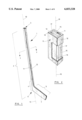
- FIG. 1 is a schematic perspective view of an example hockey stick in accordance with the present invention
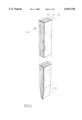
- FIG. 2 is a schematic perspective view along the longitudinal axis of the handle of a portion of the handle shown in FIG. 1 with the outer reinforcing sheath partially cut away;
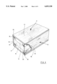
- FIG. 3 is a cross sectional view of the handle taken along lines 3--3 of FIG. 1 but with the outer reinforcing sheath removed so as to expose only the cross sectional profile of the sandwich member thereof;
- FIG. 4 is a schematic perspective side view of an example embodiment of a sandwich member in accordance with the present invention.
- FIG. 5 is a schematic perspective side view of a modified version of the sandwich member shown in FIG. 4;
- FIG. 6 is another schematic perspective view, along the longitudinal axis, of the portion of the handle shown in FIG. 2, FIG. 6 being on the same page of drawings as FIG. 2;
- FIG. 7 is the same view as shown in FIG. 3 but of another embodiment of the invention wherein the side zones and the spacer zone face both of the broad sides of the handle rather than the narrow sides;
- FIG. 8 is the same view as shown in FIG. 6 but of the other embodiment of the invention wherein the side zones and the spacer zone face both of the broad sides of the handle rather than the narrow sides;
- FIG. 9 is the same view as shown in FIG. 2 but of the other embodiment of the invention wherein the side zones and the spacer zone face both of the broad sides of the handle rather than the narrow sides;
- FIG. 10 is a schematic view of a handle component of the present invention in the process of being attached to a blade component
- FIG. 11 is a schematic cross sectional view along longitudinal axis of another example embodiment of a sandwich member of the present invention wherein the spacer zone is wedge shaped towards the rear end;
- FIG. 12 is a cross-sectional view along 12--12 of the sandwich member shown in FIG. 11;
- FIG. 13 is a cross-sectional view along 13--13 of the sandwich member shown in FIG. 11;
- FIG. 14 is a cross-sectional view of a further embodiment of a sandwich member of the present invention wherein the spacer member is diagonally disposed;
- FIG. 15 is a schematic perspective side view of an example embodiment of a spacer body, for a spacer zone, having a honey-comb like structure.
- FIG. 1 illustrates an embodiment of a hockey stick 1 in accordance with the present invention.
- the hockey stick 1 has a handle component generally designated by the reference numeral 2.
- the handle component 2 has a rear end 3 and a forward end portion 4.
- the overall length of the handle component 2 may, for example, be in the range of from about 1100 to 1650 mm (e.g. about 1540 mm); the length could of course be shorter or longer as desired or necessary.
- the hockey stick 1 also has a blade component 5.
- the blade component is attached to the forward end portion 4 of the handle component 2 at the heel 6 of the stick; the blade component 5 may be attached to the forward end portion 4 in any suitable (known) fashion (e.g. by a fibre reinforced plastics material layer(s)).
- the blade component 5 is straight and has more less planar broad front and rear faces.
- One of the blade faces is designated by the reference numeral 7; the other face is hidden there behind.
- the blade could of course take on a curved aspect in which case the broad blade face 7 could for example have a convex aspect and the hidden broad blade face a corresponding concave aspect.
- the handle component is an elongated member and has longitudinal axis 10.
- the handle component 2 has a rectangular like configuration (i.e. viewed in cross-section, the shaft 2 provides a more or less rectangular aspect or profile--see, for example FIGS. 2 and 6). Accordingly, the handle component 2 has a pair of opposed broad sides 11 and a pair of opposed narrow sides 12. As illustrated the broad and narrow faces are shown as having a planar aspect but they may of course have a curved aspect if so desired (e.g. convex or concave aspect--see for example U.S. Pat. No. 5,423,531, the entire contents of which are incorporated herein by reference).
- the handle component 2 comprises a longitudinally extending structural core component.
- the handle component 2 also has an outer sheath component which is longitudinally sheathed or disposed about the core component, i.e. the sheath component is disposed about or surrounds the core component over at least a portion of the length of the core component.
- the core component comprises a longitudinally extending sandwich member.
- the sandwich member comprises three longitudinally extending substance zones, namely two wood side zones 15 and 16 and a central or rigid foam spacer zone 17. Referring to FIG. 3, these substance zones are shown in cross sectional profile; these same zones may also be seen in FIGS. 2 and 4 to 6.
- the foam spacer zone 17 as may be appreciated spaces apart the two wood side zones 15 and 16, i.e. transversely relative to the longitudinal axis 10 of the handle component 2.
- the sandwich member may, for example, be configured so as to have a length whereby it may extend from the rear end 3 and include the front end portion 4 of the handle component 2.
- the sandwich member may be configured so as to only extend over a portion of the length of the handle component 2.
- the sandwich member may be configured so as to extend from the rear end 3 to some position intermediate the rear end 3 and the front end portion 4; the sandwich member may, alternatively, for example, be configured so as to be some distance from both the rear end 3 and the front end portion 4.
- this figure shows a sandwich member which is configured to extend from the rear end and include the front end portion of the handle component.
- the sandwich member has a rear end 3a and a forward end portion 4a; the rear end 3a is intended to form part of the rear end 3 of a handle component.
- the sandwich member has a more or less constant cross sectional profile from the rear end 3a up to and including the forward end portion 4a.
- This type of sandwich structure member may, for example, be used for a handle component wherein the forward end portion is intended to be configured for replaceably engaging in known manner the socket of a shank element of a replaceable blade component, i.e. the sandwich member may be used for forming a hockey stick of different form than that shown in FIG. 1 wherein the handle and blade are unitary and fixed to each other.
- the wood side zones of the forward end portion 4a may be shaved as by sanding or with a plane so as to remove a portion of the wood of each side zone to an inclined level designated by the dotted lines 20 and 21.
- the result is a tapered end portion wherein the thickness of the outer side zones decrease to thickness 22 and 23 which is smaller than the thickness of the side zones in the rest of the sandwich member; the cross sectional profile of the sandwich member otherwise stays rectangular across the tapering forward end portion.
- FIG. 5 which shows an example of such a modified sandwich member
- the side zones are worked so as to taper inwardly to the terminal forward part of the sandwich member so as to give a forward end portion 4b having a wedge like aspect.
- the sandwich member thus has a more or less constant cross sectional profile from the rear end 3a up to the forward end portion 4b, i.e. not including the forward end portion 4b.
- This type of wedged sandwich member may for example be used to form a handle as shown in FIG. 1 (see FIG. 10 as well as U.S. Pat. No. 5,407,195).
- the substance of the foam spacer zone 17 in the example embodiments shown in these figures is composed in its entirety of a single body of rigid foam extending from the rear end to the forward end portion.
- the substance of the wood side zones 15 and 16 in the example embodiments shown in these figures are each composed in their entireties of a single body of wood extending from the rear end to the forward end portion.
- the bodies may be unitary in the sense of being obtained from (e.g. cut out from) a single piece of foam or wood or they may be composed of a plurality of pieces of foam or wood suitably fixed (e.g. glued) together as the case may be (i.e. be a composite foam or wood material).
- the bodies of foam and wood are shown as being more or less continuous they may be discontinuous or broken e.g. the bodies may be interrupted for example by openings or spaces.
- one or more of the zones e.g. the rigid foam spacer zone
- this figure shows a cross sectional profile of the sandwich member (i.e. perpendicularly to the length of the sandwich member).
- the zones are shown as having a common width 25.
- the side zones 15 and 16 are also shown as having thicknesses 26 and 27 which are also more or less the same.
- the spacer zone 17 has a thickness 28 which is larger than the individual thickness of either of the side zones.
- the combined thicknesses of the zones defines the thickness of the sandwich member.
- the thicknesses of each zone will as may be understood be more or less constant over the length of the sandwich member, i.e. so as to give the sandwich member a more or less constant thickness over its entire length.
- the thicknesses of the side zones in the forward end portion 4b decreases towards the terminal end of the forward portion of this sandwich member, i.e. the thickness of the sandwich zone is not constant over its entire length.
- the thickness of each of the zones may, for example, be varied so as to provide the spacer zone with a longitudinally extending wedge like configuration wherein the thickness of the spacer zone diminishes towards the rear end, e.g. in addition to a wedgelike shape at the forward end; see FIGS. 11, 12 and 13.
- a sandwich member such as shown in FIGS. 2, 3 and 6 (as well as in FIGS. 4 and 5) has a pair of opposed broad sides and a pair of opposed narrow sides.
- the side zones each on their respective own (i.e. individually) define a respective broad side of the sandwich member, i.e. the side zones each face a corresponding broad side of the handle component.
- the side zones and the spacer zone together define each of the narrow sides of the sandwich member, i.e. the side zones and the spacer zone together each face the corresponding narrow sides of the handle component.
- the various materials or substances of the zones of the sandwich member may be fixed or held together in any suitable fashion; the materials may for example be attached together as by glue, bonding resin or any other type of suitable (known) adhesive); e.g. by any suitable (known) epoxy resin adhesive substance.
- the faces of the broad and narrow sides of the handle component shown in FIGS. 1, 2, and 6 are defined by the outer sheath component.
- the sandwich member need not be covered by such a sheath (e.g. one or more sides thereof need not be so covered).
- such a sheath may be used so as to modify (e.g. reinforce) in a desired or suitable fashion the strength or rigidity characteristics of the handle as well as to facilitate sanding and/or provide an aesthetic quality to the handle.
- the sheath component for the handle component of FIG. 1 is a composite reinforcing means which comprises a number of strengthening or stiffening layers and as desired aesthetic sandable wood veneer layers.
- the sandwich member may be longitudinally covered on the broad sides thereof by two layers 30 of unidirectional glass/carbon fibres in a resin (e.g. epoxy resin) such as obtainable from FIBRES ARMTEX INC. MAGOG QUEBEC CANADA.
- the unidirectional fibres are shown as lines one of which is designated with the reference numeral 31.
- the narrow sides may be covered by a layer 35 of unidirectional glass and/or carbon fibres in a resin (e.g. epoxy resin) such as obtainable from FIBRES ARMTEX INC.
- the glass and/or carbon fibre layer 35 on the narrow sides may be covered by a thin layer of birch wood 36 for facilitating sanding as well as for aesthetic purposes.
- the various layers are fixed to the sandwich member in any suitable fashion (e.g. glue, bonding resin or any other type of suitable (known) adhesive); if desired the outer surface may be covered by a suitable resin provided that the desired weight/strength characteristics are obtained.
- FIGS. 7, 8 and 9 illustrate another example embodiment of a handle component of the present invention.
- the spacer zone and the side zones face together each face the broad side of the handle rather than the narrow side.
- the handle component of these figures may be used to replace the handle component shown in FIGS. 2 to 6, i.e. with appropriate tapering of all three zones in the area of the forward end portion.
- this figure shows a cross sectional profile of the alternate sandwich member (i.e. perpendicularly to the length of the sandwich member).
- the zones are shown as having a common thickness 25a.
- the side zones 15a and 16a are also shown as having widths 26a and 27a which are also more or less the same.
- the spacer zone 17a has a width 28a which is larger than the individual thickness of either of the side zones.
- the combined widths of the zones defines the width of the sandwich member. The widths can vary in analogous fashion as discussed above with respect to the thicknesses of the zones for the sandwich members illustrated in FIGS. 2 to 6.
- a sandwich member such as shown in FIGS. 7, 8 and 9 also has a pair of opposed broad sides and a pair of opposed narrow sides.
- the side zones each on their respective own (i.e. individually) define a respective narrow side of the sandwich member, i.e. the side zones each face a corresponding narrow side of the handle component.
- the side zones and the spacer zone together define each of the broad sides of the sandwich member, i.e. the side zones and the spacer zone together each face the corresponding broad sides of the handle component.
- FIG. 10 this figure illustrate a handle component 2 and a blade component in the process of being fixed together.
- the blade at a heel part thereof is provided with a notch opening 40 configured to seat the forward end portion 4 of the handle component.
- the end portion 4 of the handle once seated in the notch 40 may be attached to the blade 2 by a fibre reinforced plastics material layer in any known manner.
- FIGS. 11, 12 and 13 illustrate another example embodiment of a sandwich member.
- the sandwich member is shown in FIG. 11 in longitudinal cross section, i.e. with a longitudinal axis 50.
- the sandwich member has wood side zones 51 and 52 disposed about a central spacer zone 53.
- the spacer zone has a wedge like configuration extending in the direction from the forward end 54 towards the rear end 55, i.e. the thickness of the spacer zone diminishes towards the rear end 55 as may be appreciated from FIGS. 12 and 13.
- This type of construction may be used for example if it is desired to shift the centre of gravity of the handle towards the rear end of the handle.
- FIG. 14 shows another possible configuration for the sandwich member.
- the central spacer zone 60 disposed between the side zones 61 and 62 has a cross section aspect which is of a non-rectangular parallelogram type over the longitudinal length of the handle; in contrast the FIGS. 3 and 4 for example show a spacer zone having a non-rectangular parallelogram aspect.
- FIG. 15 is a schematic perspective side view of an example embodiment of a rigid foam spacer body for a spacer zone, the spacer body 67 having a honey-comb like structure.
- the spacer body is provides with a plurality of hexagonally shaped openings which extend from one side to the other of the spacer body; only a few of the opening are actually shown, one of which is designated with the reference numeral 68.
- the provision of the openings may be used as a mechanism to vary the density of the spacer zone.
Abstract
Description
Claims (16)
Priority Applications (1)
| Application Number | Priority Date | Filing Date | Title |
|---|---|---|---|
| US09/133,189 US6033328A (en) | 1996-11-04 | 1998-08-13 | Hockey stick shaft |
Applications Claiming Priority (2)
| Application Number | Priority Date | Filing Date | Title |
|---|---|---|---|
| US74311996A | 1996-11-04 | 1996-11-04 | |
| US09/133,189 US6033328A (en) | 1996-11-04 | 1998-08-13 | Hockey stick shaft |
Related Parent Applications (1)
| Application Number | Title | Priority Date | Filing Date |
|---|---|---|---|
| US74311996A Continuation | 1996-11-04 | 1996-11-04 |
Publications (1)
| Publication Number | Publication Date |
|---|---|
| US6033328A true US6033328A (en) | 2000-03-07 |
Family
ID=24987587
Family Applications (1)
| Application Number | Title | Priority Date | Filing Date |
|---|---|---|---|
| US09/133,189 Expired - Fee Related US6033328A (en) | 1996-11-04 | 1998-08-13 | Hockey stick shaft |
Country Status (1)
| Country | Link |
|---|---|
| US (1) | US6033328A (en) |
Cited By (32)
| Publication number | Priority date | Publication date | Assignee | Title |
|---|---|---|---|---|
| US6165051A (en) * | 1998-10-29 | 2000-12-26 | Kulicke & Soffa Investments, Inc. | Monitoring system for dicing saws |
| WO2002004078A1 (en) * | 2000-07-10 | 2002-01-17 | True Temper Sports, Inc. | Hockey stick with reinforced shaft |
| US6358166B1 (en) * | 1999-11-10 | 2002-03-19 | Kuo-Pin Yu | Hockey stick |
| US6656058B2 (en) * | 2002-01-31 | 2003-12-02 | James Thompson | Torque minimization apparatus for a golf club |
| US20040102263A1 (en) * | 2002-11-05 | 2004-05-27 | Ray Blotteaux | Impact layer technology shaft |
| US20040198538A1 (en) * | 2000-09-15 | 2004-10-07 | Jas. D. Easton | Hockey stick |
| US20040235592A1 (en) * | 2000-09-15 | 2004-11-25 | Mcgrath Michael J. | Hockey stick |
| US20050043123A1 (en) * | 2003-08-22 | 2005-02-24 | Harvey Charles M. | Lacrosse stick |
| US20050090339A1 (en) * | 2003-10-24 | 2005-04-28 | Adam Gans | Hockey stick blade |
| US20050156358A1 (en) * | 2004-01-15 | 2005-07-21 | Alain Bellefleur | Method of making a formable hockey stick blade |
| US20050176529A1 (en) * | 2003-11-19 | 2005-08-11 | Frischmon Timm J. | Apparatus and method for repairing a hockey stick shaft |
| US20060019777A1 (en) * | 2004-07-26 | 2006-01-26 | Quikstick Lacrosse, Llc | Lacrosse stick |
| US20060090838A1 (en) * | 2004-10-28 | 2006-05-04 | Alain Bellefleur | Method of making a formable hockey stick blade |
| US20060287142A1 (en) * | 2000-01-07 | 2006-12-21 | Jas. D. Easton, Inc., A California Corporation | Hockey stick |
| US20070155548A1 (en) * | 2005-11-16 | 2007-07-05 | Easton Sports, Inc. | Hockey stick |
| US20070249437A1 (en) * | 2003-05-15 | 2007-10-25 | Jas. D. Easton, Inc. | Hockey stick |
| US20080020872A1 (en) * | 2006-07-24 | 2008-01-24 | Johnson Benjamin J | Hockey stick |
| US7329195B2 (en) | 2003-03-13 | 2008-02-12 | Mission Itech Hockey, Inc. | Durable high performance hockey stick |
| US20080093765A1 (en) * | 2004-02-06 | 2008-04-24 | Bauer Nike Hockey Inc. | Method of making a hockey stick blade |
| GB2443167A (en) * | 2006-10-26 | 2008-04-30 | Rivdal Developments Ltd | Hurley stick |
| US20100035708A1 (en) * | 2008-08-06 | 2010-02-11 | Easton Sports, Inc. | Hockey stick |
| US7931549B2 (en) | 2009-07-30 | 2011-04-26 | Sport Maska Inc. | Ice hockey stick |
| USD770581S1 (en) * | 2015-06-15 | 2016-11-01 | Sport Maska Inc. | Hockey stick |
| USD770582S1 (en) | 2015-06-15 | 2016-11-01 | Sport Maska Inc. | Goalie stick |
| US9511268B1 (en) * | 2015-06-02 | 2016-12-06 | Michael Levy | Stick assembly |
| US20170101878A1 (en) * | 2015-10-08 | 2017-04-13 | General Electric Company | Low modulus insert for a component of a gas turbine engine |
| US20170100651A1 (en) * | 2015-10-08 | 2017-04-13 | Michael E. Kordecki | Safety hockey stick |
| US20170101876A1 (en) * | 2015-10-08 | 2017-04-13 | General Electric Company | Fan platform for a gas turbine engine |
| US20180200591A1 (en) * | 2014-05-13 | 2018-07-19 | Bauer Hockey, Llc | Sporting Goods Including Microlattice Structures |
| RU182558U1 (en) * | 2017-05-12 | 2018-08-22 | Евгений Вячеславович Куров | Hockey stick |
| US10315082B1 (en) | 2017-11-30 | 2019-06-11 | Bauer Hockey, Llc | Hockey stick with co-molded construction |
| US11684104B2 (en) | 2019-05-21 | 2023-06-27 | Bauer Hockey Llc | Helmets comprising additively-manufactured components |
Citations (17)
| Publication number | Priority date | Publication date | Assignee | Title |
|---|---|---|---|---|
| US3934875A (en) * | 1974-02-14 | 1976-01-27 | James Leland Easton | Hockey stick |
| US3972528A (en) * | 1975-02-14 | 1976-08-03 | Pepsico Inc. | Baseball bat grip |
| US3982760A (en) * | 1973-12-13 | 1976-09-28 | Karhu-Titan Oy | Stick for hockey or the like |
| US4059269A (en) * | 1974-11-26 | 1977-11-22 | Karhu-Titan Oy | Hockey stick or the like, particularly blade structure thereof |
| US4124208A (en) * | 1977-05-09 | 1978-11-07 | Numerical Control, Inc. | Hockey stick construction |
| US4200479A (en) * | 1976-03-12 | 1980-04-29 | La Corporation Inglasco Ltee | Method of making a hockey stick |
| US4591155A (en) * | 1985-02-20 | 1986-05-27 | Yutaka Adachi | Method of making hockey sticks |
| US4684130A (en) * | 1982-12-23 | 1987-08-04 | Inclasco Corporation Ltd. | Ice hockey stick |
| US4689130A (en) * | 1984-04-27 | 1987-08-25 | Atochem | Continuous production of higher chloroalkanes |
| CA1230898A (en) * | 1984-09-24 | 1987-12-29 | Karhu-Titan Oy | Shaft structure for sports equipment |
| US4968257A (en) * | 1989-02-27 | 1990-11-06 | Yalen William J | Computer-based teaching apparatus |
| US5050878A (en) * | 1988-10-07 | 1991-09-24 | Destra S.A. | Hockey stick made of composite materials and its manufacturing process |
| US5217221A (en) * | 1990-05-04 | 1993-06-08 | The Baum Research & Development Company, Inc. | Hockey stick formed of composite materials |
| US5333857A (en) * | 1992-10-15 | 1994-08-02 | Composites-Busch & Cie | Hockey stick |
| US5407195A (en) * | 1992-10-06 | 1995-04-18 | K.C.G. Hockey Finland Oy | Blade construct for a hockey stick or the like |
| US5419553A (en) * | 1992-09-30 | 1995-05-30 | Ronald Salcer | Hockey stick shaft |
| US5439215A (en) * | 1994-01-25 | 1995-08-08 | Power Stick Manufacturing, Inc. | Composite, pultruded fiberglass resinous hockey stick, method and device for manufacture thereof |
-
1998
- 1998-08-13 US US09/133,189 patent/US6033328A/en not_active Expired - Fee Related
Patent Citations (17)
| Publication number | Priority date | Publication date | Assignee | Title |
|---|---|---|---|---|
| US3982760A (en) * | 1973-12-13 | 1976-09-28 | Karhu-Titan Oy | Stick for hockey or the like |
| US3934875A (en) * | 1974-02-14 | 1976-01-27 | James Leland Easton | Hockey stick |
| US4059269A (en) * | 1974-11-26 | 1977-11-22 | Karhu-Titan Oy | Hockey stick or the like, particularly blade structure thereof |
| US3972528A (en) * | 1975-02-14 | 1976-08-03 | Pepsico Inc. | Baseball bat grip |
| US4200479A (en) * | 1976-03-12 | 1980-04-29 | La Corporation Inglasco Ltee | Method of making a hockey stick |
| US4124208A (en) * | 1977-05-09 | 1978-11-07 | Numerical Control, Inc. | Hockey stick construction |
| US4684130A (en) * | 1982-12-23 | 1987-08-04 | Inclasco Corporation Ltd. | Ice hockey stick |
| US4689130A (en) * | 1984-04-27 | 1987-08-25 | Atochem | Continuous production of higher chloroalkanes |
| CA1230898A (en) * | 1984-09-24 | 1987-12-29 | Karhu-Titan Oy | Shaft structure for sports equipment |
| US4591155A (en) * | 1985-02-20 | 1986-05-27 | Yutaka Adachi | Method of making hockey sticks |
| US5050878A (en) * | 1988-10-07 | 1991-09-24 | Destra S.A. | Hockey stick made of composite materials and its manufacturing process |
| US4968257A (en) * | 1989-02-27 | 1990-11-06 | Yalen William J | Computer-based teaching apparatus |
| US5217221A (en) * | 1990-05-04 | 1993-06-08 | The Baum Research & Development Company, Inc. | Hockey stick formed of composite materials |
| US5419553A (en) * | 1992-09-30 | 1995-05-30 | Ronald Salcer | Hockey stick shaft |
| US5407195A (en) * | 1992-10-06 | 1995-04-18 | K.C.G. Hockey Finland Oy | Blade construct for a hockey stick or the like |
| US5333857A (en) * | 1992-10-15 | 1994-08-02 | Composites-Busch & Cie | Hockey stick |
| US5439215A (en) * | 1994-01-25 | 1995-08-08 | Power Stick Manufacturing, Inc. | Composite, pultruded fiberglass resinous hockey stick, method and device for manufacture thereof |
Cited By (57)
| Publication number | Priority date | Publication date | Assignee | Title |
|---|---|---|---|---|
| US6165051A (en) * | 1998-10-29 | 2000-12-26 | Kulicke & Soffa Investments, Inc. | Monitoring system for dicing saws |
| US6358166B1 (en) * | 1999-11-10 | 2002-03-19 | Kuo-Pin Yu | Hockey stick |
| US20060287142A1 (en) * | 2000-01-07 | 2006-12-21 | Jas. D. Easton, Inc., A California Corporation | Hockey stick |
| WO2002004078A1 (en) * | 2000-07-10 | 2002-01-17 | True Temper Sports, Inc. | Hockey stick with reinforced shaft |
| US7850553B2 (en) | 2000-09-15 | 2010-12-14 | Easton Sports, Inc. | Hockey stick |
| US20040235592A1 (en) * | 2000-09-15 | 2004-11-25 | Mcgrath Michael J. | Hockey stick |
| US20090093326A1 (en) * | 2000-09-15 | 2009-04-09 | Goldsmith Edward M | Hockey Stick |
| US7789778B2 (en) | 2000-09-15 | 2010-09-07 | Easton Sports, Inc. | Hockey stick |
| US7963868B2 (en) | 2000-09-15 | 2011-06-21 | Easton Sports, Inc. | Hockey stick |
| US20040198538A1 (en) * | 2000-09-15 | 2004-10-07 | Jas. D. Easton | Hockey stick |
| US8517868B2 (en) | 2000-09-15 | 2013-08-27 | Easton Sports, Inc. | Hockey stick |
| US8216096B2 (en) | 2000-09-15 | 2012-07-10 | Easton Sports, Inc. | Hockey stick |
| US20110237365A1 (en) * | 2000-09-15 | 2011-09-29 | Mcgrath Michael J | Hockey stick |
| US20060281592A1 (en) * | 2000-09-15 | 2006-12-14 | Jas D. Easton, Inc. | Hockey Stick |
| US6656058B2 (en) * | 2002-01-31 | 2003-12-02 | James Thompson | Torque minimization apparatus for a golf club |
| US20040102263A1 (en) * | 2002-11-05 | 2004-05-27 | Ray Blotteaux | Impact layer technology shaft |
| US7128669B2 (en) | 2002-11-05 | 2006-10-31 | Sport Maska Inc. | Impact layer technology shaft |
| US7329195B2 (en) | 2003-03-13 | 2008-02-12 | Mission Itech Hockey, Inc. | Durable high performance hockey stick |
| US20070249437A1 (en) * | 2003-05-15 | 2007-10-25 | Jas. D. Easton, Inc. | Hockey stick |
| US7862456B2 (en) | 2003-05-15 | 2011-01-04 | Easton Sports, Inc. | Hockey stick |
| US20050043123A1 (en) * | 2003-08-22 | 2005-02-24 | Harvey Charles M. | Lacrosse stick |
| US6918847B2 (en) | 2003-10-24 | 2005-07-19 | Bauer Nike Hockey Inc. | Hockey stick blade |
| US20050090339A1 (en) * | 2003-10-24 | 2005-04-28 | Adam Gans | Hockey stick blade |
| US20060293128A1 (en) * | 2003-11-19 | 2006-12-28 | Frischmon Timm J | Apparatus and method for repairing a hockey stick shaft |
| US7108618B2 (en) | 2003-11-19 | 2006-09-19 | Frischmon Timm J | Apparatus and method for repairing a hockey stick shaft |
| US20050176529A1 (en) * | 2003-11-19 | 2005-08-11 | Frischmon Timm J. | Apparatus and method for repairing a hockey stick shaft |
| US20050156358A1 (en) * | 2004-01-15 | 2005-07-21 | Alain Bellefleur | Method of making a formable hockey stick blade |
| US20080093765A1 (en) * | 2004-02-06 | 2008-04-24 | Bauer Nike Hockey Inc. | Method of making a hockey stick blade |
| US7736251B2 (en) | 2004-07-26 | 2010-06-15 | Quikstick Lacrosse, Llc | Lacrosse stick |
| US20060019777A1 (en) * | 2004-07-26 | 2006-01-26 | Quikstick Lacrosse, Llc | Lacrosse stick |
| US20060090838A1 (en) * | 2004-10-28 | 2006-05-04 | Alain Bellefleur | Method of making a formable hockey stick blade |
| US7261787B2 (en) | 2004-10-28 | 2007-08-28 | Bauer Nike Hockey Inc. | Method of making a formable hockey stick blade |
| US20070155548A1 (en) * | 2005-11-16 | 2007-07-05 | Easton Sports, Inc. | Hockey stick |
| US20080020872A1 (en) * | 2006-07-24 | 2008-01-24 | Johnson Benjamin J | Hockey stick |
| GB2443167B (en) * | 2006-10-26 | 2008-09-10 | Rivdal Developments Ltd | A hurley stick |
| GB2443167A (en) * | 2006-10-26 | 2008-04-30 | Rivdal Developments Ltd | Hurley stick |
| US7914403B2 (en) | 2008-08-06 | 2011-03-29 | Easton Sports, Inc. | Hockey stick |
| US20100035708A1 (en) * | 2008-08-06 | 2010-02-11 | Easton Sports, Inc. | Hockey stick |
| US7931549B2 (en) | 2009-07-30 | 2011-04-26 | Sport Maska Inc. | Ice hockey stick |
| US20190290982A1 (en) * | 2014-05-13 | 2019-09-26 | Bauer Hockey, Llc | Sporting Goods Including Microlattice Structures |
| US11844986B2 (en) * | 2014-05-13 | 2023-12-19 | Bauer Hockey Llc | Sporting goods including microlattice structures |
| US11794084B2 (en) | 2014-05-13 | 2023-10-24 | Bauer Hockey Llc | Sporting goods including microlattice structures |
| US20180200591A1 (en) * | 2014-05-13 | 2018-07-19 | Bauer Hockey, Llc | Sporting Goods Including Microlattice Structures |
| US11779821B2 (en) * | 2014-05-13 | 2023-10-10 | Bauer Hockey Llc | Sporting goods including microlattice structures |
| US11547912B2 (en) | 2014-05-13 | 2023-01-10 | Bauer Hockey Ltd. | Sporting goods including microlattice structures |
| US9511268B1 (en) * | 2015-06-02 | 2016-12-06 | Michael Levy | Stick assembly |
| USD770581S1 (en) * | 2015-06-15 | 2016-11-01 | Sport Maska Inc. | Hockey stick |
| USD770582S1 (en) | 2015-06-15 | 2016-11-01 | Sport Maska Inc. | Goalie stick |
| US20170100651A1 (en) * | 2015-10-08 | 2017-04-13 | Michael E. Kordecki | Safety hockey stick |
| US10605117B2 (en) * | 2015-10-08 | 2020-03-31 | General Electric Company | Fan platform for a gas turbine engine |
| US20170101876A1 (en) * | 2015-10-08 | 2017-04-13 | General Electric Company | Fan platform for a gas turbine engine |
| US20170101878A1 (en) * | 2015-10-08 | 2017-04-13 | General Electric Company | Low modulus insert for a component of a gas turbine engine |
| RU182558U1 (en) * | 2017-05-12 | 2018-08-22 | Евгений Вячеславович Куров | Hockey stick |
| US10596431B2 (en) | 2017-11-30 | 2020-03-24 | Bauer Hockey, Llc | Hockey stick with co-molded construction |
| US11020642B2 (en) | 2017-11-30 | 2021-06-01 | Bauer Hockey, Llc | Hockey stick with co-molded construction |
| US10315082B1 (en) | 2017-11-30 | 2019-06-11 | Bauer Hockey, Llc | Hockey stick with co-molded construction |
| US11684104B2 (en) | 2019-05-21 | 2023-06-27 | Bauer Hockey Llc | Helmets comprising additively-manufactured components |
Similar Documents
| Publication | Publication Date | Title |
|---|---|---|
| US6033328A (en) | Hockey stick shaft | |
| US7422532B2 (en) | Hockey stick | |
| US6520530B1 (en) | Core for a gliding board | |
| US20050153799A1 (en) | Sports equipment stick with truss construction | |
| US20030004019A1 (en) | Blade core for hockey stick and the like | |
| US6612605B2 (en) | Integrated modular glide board | |
| US4706985A (en) | Alpine ski with selective reinforcement | |
| JPS63229081A (en) | Ski board | |
| US20090108554A1 (en) | Skateboard deck | |
| CZ339296A3 (en) | Holder of an ice-hockey stick or for a game of similar type | |
| EP1137461A1 (en) | Core for a gliding board | |
| EP2000180B1 (en) | Snowboard or skateboard with reinforcement made of natural fibers | |
| US20060281591A1 (en) | Stick for practising sports | |
| US4324400A (en) | Table tennis bat blade | |
| US5697857A (en) | Plastic hockey stick blade structure | |
| FR2565837A1 (en) | WOODEN CORE SKI AND FOAM COMPRISING STRAINING SPACERS | |
| US4968032A (en) | Hockey stick shaft | |
| US20050153798A1 (en) | Sports equipment stick with truss construction | |
| US4523772A (en) | Sandwich type construction multilayer skis | |
| US20040087395A1 (en) | Concave/sided oval hockey stick shaft (a.k.a. the CSO) with natural, horizontal, elliptical/oval convex (of oval geometry) top and bottom planes, and natural, vertical, elliptical/oval concaved (of oval geometry) side walls: referencing the cross-sectional aspect of the shaft itself | |
| EP1064056A1 (en) | Hockey stick shaft | |
| DE3826986C2 (en) | ||
| CA2189509A1 (en) | Hockey stick shaft | |
| US7219916B2 (en) | Snowboard | |
| US20050121881A1 (en) | Ski core |
Legal Events
| Date | Code | Title | Description |
|---|---|---|---|
| AS | Assignment |
Owner name: SLM TRADEMARK ACQUISITION CANADA CORPORATION, QUEB Free format text: SECURITY INTEREST;ASSIGNOR:SLM INTERNATIONAL, INC.;REEL/FRAME:009773/0922 Effective date: 19981119 Owner name: TROPSPORT ACQUISITIONS INC., QUEBEC Free format text: SECURITY INTEREST;ASSIGNOR:SLM INTERNATIONAL, INC.;REEL/FRAME:009773/0922 Effective date: 19981119 Owner name: GENERAL ELECTRIC CAPITAL CORPORATION, AS AGENT FOR Free format text: SECURITY INTEREST;ASSIGNOR:SLM INTERNATIONAL, INC.;REEL/FRAME:009773/0922 Effective date: 19981119 Owner name: CAISSE DE DEPOT ET PLACEMENT DU QUEBEC IN ITS CAPA Free format text: SECURITY INTEREST;ASSIGNOR:SLM INTERNATIONAL, INC.;REEL/FRAME:009773/0922 Effective date: 19981119 Owner name: SLM TRADEMARK ACQUISITION CORP., VERMONT Free format text: SECURITY INTEREST;ASSIGNOR:SLM INTERNATIONAL, INC.;REEL/FRAME:009773/0922 Effective date: 19981119 Owner name: SHC HOCKEY, INC., VERMONT Free format text: SECURITY INTEREST;ASSIGNOR:SLM INTERNATIONAL, INC.;REEL/FRAME:009773/0922 Effective date: 19981119 Owner name: GENERAL ELECTRIC CAPITAL CANADA INC., AS AGENT FOR Free format text: SECURITY INTEREST;ASSIGNOR:SLM INTERNATIONAL, INC.;REEL/FRAME:009773/0922 Effective date: 19981119 Owner name: SPORT MASKA INC., QUEBEC Free format text: SECURITY INTEREST;ASSIGNOR:SLM INTERNATIONAL, INC.;REEL/FRAME:009773/0922 Effective date: 19981119 Owner name: MASKA U.S., INC., VERMONT Free format text: SECURITY INTEREST;ASSIGNOR:SLM INTERNATIONAL, INC.;REEL/FRAME:009773/0922 Effective date: 19981119 Owner name: SPORTS HOLDINGS CORP., NEW YORK Free format text: SECURITY INTEREST;ASSIGNOR:SLM INTERNATIONAL, INC.;REEL/FRAME:009773/0922 Effective date: 19981119 Owner name: WAP HOLDINGS INC., DELAWARE Free format text: SECURITY INTEREST;ASSIGNOR:SLM INTERNATIONAL, INC.;REEL/FRAME:009773/0922 Effective date: 19981119 |
|
| AS | Assignment |
Owner name: SPORT MASKA INC., CANADA Free format text: MERGER;ASSIGNOR:TROPSPORT ACQUISITIONS INC.;REEL/FRAME:010226/0115 Effective date: 19990401 |
|
| FEPP | Fee payment procedure |
Free format text: PAYOR NUMBER ASSIGNED (ORIGINAL EVENT CODE: ASPN); ENTITY STATUS OF PATENT OWNER: LARGE ENTITY |
|
| FPAY | Fee payment |
Year of fee payment: 4 |
|
| REMI | Maintenance fee reminder mailed | ||
| LAPS | Lapse for failure to pay maintenance fees | ||
| STCH | Information on status: patent discontinuation |
Free format text: PATENT EXPIRED DUE TO NONPAYMENT OF MAINTENANCE FEES UNDER 37 CFR 1.362 |
|
| FP | Lapsed due to failure to pay maintenance fee |
Effective date: 20080307 |