US6012522A - Deformable well screen - Google Patents
Deformable well screen Download PDFInfo
- Publication number
- US6012522A US6012522A US09/233,303 US23330399A US6012522A US 6012522 A US6012522 A US 6012522A US 23330399 A US23330399 A US 23330399A US 6012522 A US6012522 A US 6012522A
- Authority
- US
- United States
- Prior art keywords
- screen
- tube
- slots
- well
- filter layer
- Prior art date
- Legal status (The legal status is an assumption and is not a legal conclusion. Google has not performed a legal analysis and makes no representation as to the accuracy of the status listed.)
- Expired - Lifetime
Links
- 238000004519 manufacturing process Methods 0.000 claims abstract description 10
- 239000004215 Carbon black (E152) Substances 0.000 claims abstract description 8
- 229930195733 hydrocarbon Natural products 0.000 claims abstract description 8
- 150000002430 hydrocarbons Chemical class 0.000 claims abstract description 7
- 239000002245 particle Substances 0.000 claims abstract description 6
- 230000005012 migration Effects 0.000 claims abstract description 4
- 238000013508 migration Methods 0.000 claims abstract description 4
- 239000007787 solid Substances 0.000 claims abstract description 4
- 239000008187 granular material Substances 0.000 claims description 15
- PXHVJJICTQNCMI-UHFFFAOYSA-N Nickel Chemical compound [Ni] PXHVJJICTQNCMI-UHFFFAOYSA-N 0.000 claims description 14
- 238000000034 method Methods 0.000 claims description 14
- 238000009434 installation Methods 0.000 claims description 8
- 239000007767 bonding agent Substances 0.000 claims description 6
- 229910052759 nickel Inorganic materials 0.000 claims description 6
- 238000011065 in-situ storage Methods 0.000 claims description 3
- 230000001939 inductive effect Effects 0.000 claims description 3
- 239000011148 porous material Substances 0.000 claims description 3
- 239000004744 fabric Substances 0.000 abstract description 12
- 229910052751 metal Inorganic materials 0.000 abstract description 12
- 239000002184 metal Substances 0.000 abstract description 12
- 239000011347 resin Substances 0.000 abstract description 7
- 229920005989 resin Polymers 0.000 abstract description 7
- 239000007931 coated granule Substances 0.000 abstract description 5
- 239000004746 geotextile Substances 0.000 abstract description 3
- 239000010410 layer Substances 0.000 description 45
- 239000004576 sand Substances 0.000 description 24
- 230000001681 protective effect Effects 0.000 description 12
- 239000011241 protective layer Substances 0.000 description 11
- 229910000831 Steel Inorganic materials 0.000 description 10
- 239000010959 steel Substances 0.000 description 10
- 239000000463 material Substances 0.000 description 6
- 230000008569 process Effects 0.000 description 6
- 239000012530 fluid Substances 0.000 description 5
- 230000015572 biosynthetic process Effects 0.000 description 4
- 230000008859 change Effects 0.000 description 4
- 229910003460 diamond Inorganic materials 0.000 description 4
- 239000010432 diamond Substances 0.000 description 4
- 230000001965 increasing effect Effects 0.000 description 4
- 238000002347 injection Methods 0.000 description 4
- 239000007924 injection Substances 0.000 description 4
- 238000005245 sintering Methods 0.000 description 4
- 229920002994 synthetic fiber Polymers 0.000 description 4
- 238000009941 weaving Methods 0.000 description 4
- 238000004804 winding Methods 0.000 description 4
- 230000008901 benefit Effects 0.000 description 3
- 230000001788 irregular Effects 0.000 description 3
- XLYOFNOQVPJJNP-UHFFFAOYSA-N water Substances O XLYOFNOQVPJJNP-UHFFFAOYSA-N 0.000 description 3
- 229920013687 Carilon Polymers 0.000 description 2
- 239000004760 aramid Substances 0.000 description 2
- 229920006231 aramid fiber Polymers 0.000 description 2
- 238000005452 bending Methods 0.000 description 2
- 230000008602 contraction Effects 0.000 description 2
- 230000003628 erosive effect Effects 0.000 description 2
- 238000007689 inspection Methods 0.000 description 2
- 239000011159 matrix material Substances 0.000 description 2
- 230000035699 permeability Effects 0.000 description 2
- 229920000642 polymer Polymers 0.000 description 2
- 239000012209 synthetic fiber Substances 0.000 description 2
- UGFAIRIUMAVXCW-UHFFFAOYSA-N Carbon monoxide Chemical compound [O+]#[C-] UGFAIRIUMAVXCW-UHFFFAOYSA-N 0.000 description 1
- 229920000271 Kevlar® Polymers 0.000 description 1
- 238000009825 accumulation Methods 0.000 description 1
- 229920005603 alternating copolymer Polymers 0.000 description 1
- 230000004888 barrier function Effects 0.000 description 1
- 229910002091 carbon monoxide Inorganic materials 0.000 description 1
- 239000000919 ceramic Substances 0.000 description 1
- 238000005056 compaction Methods 0.000 description 1
- 150000001875 compounds Chemical class 0.000 description 1
- 230000006835 compression Effects 0.000 description 1
- 238000007906 compression Methods 0.000 description 1
- 229910052878 cordierite Inorganic materials 0.000 description 1
- JSKIRARMQDRGJZ-UHFFFAOYSA-N dimagnesium dioxido-bis[(1-oxido-3-oxo-2,4,6,8,9-pentaoxa-1,3-disila-5,7-dialuminabicyclo[3.3.1]nonan-7-yl)oxy]silane Chemical compound [Mg++].[Mg++].[O-][Si]([O-])(O[Al]1O[Al]2O[Si](=O)O[Si]([O-])(O1)O2)O[Al]1O[Al]2O[Si](=O)O[Si]([O-])(O1)O2 JSKIRARMQDRGJZ-UHFFFAOYSA-N 0.000 description 1
- 230000000694 effects Effects 0.000 description 1
- 230000002349 favourable effect Effects 0.000 description 1
- 239000000835 fiber Substances 0.000 description 1
- 238000001914 filtration Methods 0.000 description 1
- 230000004907 flux Effects 0.000 description 1
- 239000002783 friction material Substances 0.000 description 1
- 238000001891 gel spinning Methods 0.000 description 1
- 125000001183 hydrocarbyl group Chemical group 0.000 description 1
- 229910052500 inorganic mineral Inorganic materials 0.000 description 1
- 230000003993 interaction Effects 0.000 description 1
- 239000004761 kevlar Substances 0.000 description 1
- 230000014759 maintenance of location Effects 0.000 description 1
- 238000002074 melt spinning Methods 0.000 description 1
- 239000011707 mineral Substances 0.000 description 1
- 239000003129 oil well Substances 0.000 description 1
- 238000012856 packing Methods 0.000 description 1
- 229920005594 polymer fiber Polymers 0.000 description 1
- 238000004080 punching Methods 0.000 description 1
- 238000013000 roll bending Methods 0.000 description 1
- 238000005096 rolling process Methods 0.000 description 1
- 238000004904 shortening Methods 0.000 description 1
- 239000000126 substance Substances 0.000 description 1
- 230000002459 sustained effect Effects 0.000 description 1
- 239000008399 tap water Substances 0.000 description 1
- 235000020679 tap water Nutrition 0.000 description 1
- 230000000007 visual effect Effects 0.000 description 1
- 238000011179 visual inspection Methods 0.000 description 1
- 238000003466 welding Methods 0.000 description 1
Images


Classifications
-
- E—FIXED CONSTRUCTIONS
- E21—EARTH DRILLING; MINING
- E21B—EARTH DRILLING, e.g. DEEP DRILLING; OBTAINING OIL, GAS, WATER, SOLUBLE OR MELTABLE MATERIALS OR A SLURRY OF MINERALS FROM WELLS
- E21B43/00—Methods or apparatus for obtaining oil, gas, water, soluble or meltable materials or a slurry of minerals from wells
- E21B43/02—Subsoil filtering
- E21B43/10—Setting of casings, screens, liners or the like in wells
- E21B43/103—Setting of casings, screens, liners or the like in wells of expandable casings, screens, liners, or the like
- E21B43/108—Expandable screens or perforated liners
-
- B—PERFORMING OPERATIONS; TRANSPORTING
- B01—PHYSICAL OR CHEMICAL PROCESSES OR APPARATUS IN GENERAL
- B01D—SEPARATION
- B01D29/00—Filters with filtering elements stationary during filtration, e.g. pressure or suction filters, not covered by groups B01D24/00 - B01D27/00; Filtering elements therefor
- B01D29/11—Filters with filtering elements stationary during filtration, e.g. pressure or suction filters, not covered by groups B01D24/00 - B01D27/00; Filtering elements therefor with bag, cage, hose, tube, sleeve or like filtering elements
- B01D29/13—Supported filter elements
- B01D29/15—Supported filter elements arranged for inward flow filtration
- B01D29/21—Supported filter elements arranged for inward flow filtration with corrugated, folded or wound sheets
- B01D29/216—Supported filter elements arranged for inward flow filtration with corrugated, folded or wound sheets with wound sheets
-
- B—PERFORMING OPERATIONS; TRANSPORTING
- B01—PHYSICAL OR CHEMICAL PROCESSES OR APPARATUS IN GENERAL
- B01D—SEPARATION
- B01D29/00—Filters with filtering elements stationary during filtration, e.g. pressure or suction filters, not covered by groups B01D24/00 - B01D27/00; Filtering elements therefor
- B01D29/50—Filters with filtering elements stationary during filtration, e.g. pressure or suction filters, not covered by groups B01D24/00 - B01D27/00; Filtering elements therefor with multiple filtering elements, characterised by their mutual disposition
- B01D29/52—Filters with filtering elements stationary during filtration, e.g. pressure or suction filters, not covered by groups B01D24/00 - B01D27/00; Filtering elements therefor with multiple filtering elements, characterised by their mutual disposition in parallel connection
- B01D29/54—Filters with filtering elements stationary during filtration, e.g. pressure or suction filters, not covered by groups B01D24/00 - B01D27/00; Filtering elements therefor with multiple filtering elements, characterised by their mutual disposition in parallel connection arranged concentrically or coaxially
-
- B—PERFORMING OPERATIONS; TRANSPORTING
- B01—PHYSICAL OR CHEMICAL PROCESSES OR APPARATUS IN GENERAL
- B01D—SEPARATION
- B01D29/00—Filters with filtering elements stationary during filtration, e.g. pressure or suction filters, not covered by groups B01D24/00 - B01D27/00; Filtering elements therefor
- B01D29/50—Filters with filtering elements stationary during filtration, e.g. pressure or suction filters, not covered by groups B01D24/00 - B01D27/00; Filtering elements therefor with multiple filtering elements, characterised by their mutual disposition
- B01D29/56—Filters with filtering elements stationary during filtration, e.g. pressure or suction filters, not covered by groups B01D24/00 - B01D27/00; Filtering elements therefor with multiple filtering elements, characterised by their mutual disposition in series connection
- B01D29/58—Filters with filtering elements stationary during filtration, e.g. pressure or suction filters, not covered by groups B01D24/00 - B01D27/00; Filtering elements therefor with multiple filtering elements, characterised by their mutual disposition in series connection arranged concentrically or coaxially
-
- B—PERFORMING OPERATIONS; TRANSPORTING
- B01—PHYSICAL OR CHEMICAL PROCESSES OR APPARATUS IN GENERAL
- B01D—SEPARATION
- B01D29/00—Filters with filtering elements stationary during filtration, e.g. pressure or suction filters, not covered by groups B01D24/00 - B01D27/00; Filtering elements therefor
- B01D29/96—Filters with filtering elements stationary during filtration, e.g. pressure or suction filters, not covered by groups B01D24/00 - B01D27/00; Filtering elements therefor in which the filtering elements are moved between filtering operations; Particular measures for removing or replacing the filtering elements; Transport systems for filters
-
- B—PERFORMING OPERATIONS; TRANSPORTING
- B01—PHYSICAL OR CHEMICAL PROCESSES OR APPARATUS IN GENERAL
- B01D—SEPARATION
- B01D39/00—Filtering material for liquid or gaseous fluids
- B01D39/08—Filter cloth, i.e. woven, knitted or interlaced material
- B01D39/083—Filter cloth, i.e. woven, knitted or interlaced material of organic material
-
- B—PERFORMING OPERATIONS; TRANSPORTING
- B01—PHYSICAL OR CHEMICAL PROCESSES OR APPARATUS IN GENERAL
- B01D—SEPARATION
- B01D39/00—Filtering material for liquid or gaseous fluids
- B01D39/08—Filter cloth, i.e. woven, knitted or interlaced material
- B01D39/086—Filter cloth, i.e. woven, knitted or interlaced material of inorganic material
-
- B—PERFORMING OPERATIONS; TRANSPORTING
- B01—PHYSICAL OR CHEMICAL PROCESSES OR APPARATUS IN GENERAL
- B01D—SEPARATION
- B01D39/00—Filtering material for liquid or gaseous fluids
- B01D39/10—Filter screens essentially made of metal
-
- B—PERFORMING OPERATIONS; TRANSPORTING
- B01—PHYSICAL OR CHEMICAL PROCESSES OR APPARATUS IN GENERAL
- B01D—SEPARATION
- B01D39/00—Filtering material for liquid or gaseous fluids
- B01D39/14—Other self-supporting filtering material ; Other filtering material
-
- E—FIXED CONSTRUCTIONS
- E21—EARTH DRILLING; MINING
- E21B—EARTH DRILLING, e.g. DEEP DRILLING; OBTAINING OIL, GAS, WATER, SOLUBLE OR MELTABLE MATERIALS OR A SLURRY OF MINERALS FROM WELLS
- E21B43/00—Methods or apparatus for obtaining oil, gas, water, soluble or meltable materials or a slurry of minerals from wells
- E21B43/02—Subsoil filtering
- E21B43/04—Gravelling of wells
-
- E—FIXED CONSTRUCTIONS
- E21—EARTH DRILLING; MINING
- E21B—EARTH DRILLING, e.g. DEEP DRILLING; OBTAINING OIL, GAS, WATER, SOLUBLE OR MELTABLE MATERIALS OR A SLURRY OF MINERALS FROM WELLS
- E21B43/00—Methods or apparatus for obtaining oil, gas, water, soluble or meltable materials or a slurry of minerals from wells
- E21B43/02—Subsoil filtering
- E21B43/08—Screens or liners
- E21B43/082—Screens comprising porous materials, e.g. prepacked screens
-
- E—FIXED CONSTRUCTIONS
- E21—EARTH DRILLING; MINING
- E21B—EARTH DRILLING, e.g. DEEP DRILLING; OBTAINING OIL, GAS, WATER, SOLUBLE OR MELTABLE MATERIALS OR A SLURRY OF MINERALS FROM WELLS
- E21B43/00—Methods or apparatus for obtaining oil, gas, water, soluble or meltable materials or a slurry of minerals from wells
- E21B43/02—Subsoil filtering
- E21B43/08—Screens or liners
- E21B43/086—Screens with preformed openings, e.g. slotted liners
-
- E—FIXED CONSTRUCTIONS
- E21—EARTH DRILLING; MINING
- E21B—EARTH DRILLING, e.g. DEEP DRILLING; OBTAINING OIL, GAS, WATER, SOLUBLE OR MELTABLE MATERIALS OR A SLURRY OF MINERALS FROM WELLS
- E21B43/00—Methods or apparatus for obtaining oil, gas, water, soluble or meltable materials or a slurry of minerals from wells
- E21B43/02—Subsoil filtering
- E21B43/10—Setting of casings, screens, liners or the like in wells
- E21B43/103—Setting of casings, screens, liners or the like in wells of expandable casings, screens, liners, or the like
-
- B—PERFORMING OPERATIONS; TRANSPORTING
- B01—PHYSICAL OR CHEMICAL PROCESSES OR APPARATUS IN GENERAL
- B01D—SEPARATION
- B01D2239/00—Aspects relating to filtering material for liquid or gaseous fluids
- B01D2239/04—Additives and treatments of the filtering material
-
- B—PERFORMING OPERATIONS; TRANSPORTING
- B01—PHYSICAL OR CHEMICAL PROCESSES OR APPARATUS IN GENERAL
- B01D—SEPARATION
- B01D2239/00—Aspects relating to filtering material for liquid or gaseous fluids
- B01D2239/04—Additives and treatments of the filtering material
- B01D2239/0471—Surface coating material
- B01D2239/0485—Surface coating material on particles
-
- B—PERFORMING OPERATIONS; TRANSPORTING
- B01—PHYSICAL OR CHEMICAL PROCESSES OR APPARATUS IN GENERAL
- B01D—SEPARATION
- B01D2239/00—Aspects relating to filtering material for liquid or gaseous fluids
- B01D2239/06—Filter cloth, e.g. knitted, woven non-woven; self-supported material
- B01D2239/0604—Arrangement of the fibres in the filtering material
- B01D2239/0609—Knitted
-
- B—PERFORMING OPERATIONS; TRANSPORTING
- B01—PHYSICAL OR CHEMICAL PROCESSES OR APPARATUS IN GENERAL
- B01D—SEPARATION
- B01D2239/00—Aspects relating to filtering material for liquid or gaseous fluids
- B01D2239/06—Filter cloth, e.g. knitted, woven non-woven; self-supported material
- B01D2239/065—More than one layer present in the filtering material
- B01D2239/0668—The layers being joined by heat or melt-bonding
-
- B—PERFORMING OPERATIONS; TRANSPORTING
- B01—PHYSICAL OR CHEMICAL PROCESSES OR APPARATUS IN GENERAL
- B01D—SEPARATION
- B01D2239/00—Aspects relating to filtering material for liquid or gaseous fluids
- B01D2239/06—Filter cloth, e.g. knitted, woven non-woven; self-supported material
- B01D2239/065—More than one layer present in the filtering material
- B01D2239/0672—The layers being joined by welding
-
- B—PERFORMING OPERATIONS; TRANSPORTING
- B01—PHYSICAL OR CHEMICAL PROCESSES OR APPARATUS IN GENERAL
- B01D—SEPARATION
- B01D2239/00—Aspects relating to filtering material for liquid or gaseous fluids
- B01D2239/06—Filter cloth, e.g. knitted, woven non-woven; self-supported material
- B01D2239/065—More than one layer present in the filtering material
- B01D2239/0677—More than one layer present in the filtering material by spot-welding
-
- B—PERFORMING OPERATIONS; TRANSPORTING
- B01—PHYSICAL OR CHEMICAL PROCESSES OR APPARATUS IN GENERAL
- B01D—SEPARATION
- B01D2239/00—Aspects relating to filtering material for liquid or gaseous fluids
- B01D2239/06—Filter cloth, e.g. knitted, woven non-woven; self-supported material
- B01D2239/069—Special geometry of layers
- B01D2239/0695—Wound layers
-
- B—PERFORMING OPERATIONS; TRANSPORTING
- B01—PHYSICAL OR CHEMICAL PROCESSES OR APPARATUS IN GENERAL
- B01D—SEPARATION
- B01D2239/00—Aspects relating to filtering material for liquid or gaseous fluids
- B01D2239/08—Special characteristics of binders
- B01D2239/086—Binders between particles or fibres
-
- B—PERFORMING OPERATIONS; TRANSPORTING
- B01—PHYSICAL OR CHEMICAL PROCESSES OR APPARATUS IN GENERAL
- B01D—SEPARATION
- B01D2239/00—Aspects relating to filtering material for liquid or gaseous fluids
- B01D2239/12—Special parameters characterising the filtering material
- B01D2239/1216—Pore size
-
- B—PERFORMING OPERATIONS; TRANSPORTING
- B01—PHYSICAL OR CHEMICAL PROCESSES OR APPARATUS IN GENERAL
- B01D—SEPARATION
- B01D2239/00—Aspects relating to filtering material for liquid or gaseous fluids
- B01D2239/12—Special parameters characterising the filtering material
- B01D2239/1241—Particle diameter
-
- B—PERFORMING OPERATIONS; TRANSPORTING
- B01—PHYSICAL OR CHEMICAL PROCESSES OR APPARATUS IN GENERAL
- B01D—SEPARATION
- B01D2239/00—Aspects relating to filtering material for liquid or gaseous fluids
- B01D2239/12—Special parameters characterising the filtering material
- B01D2239/1291—Other parameters
Definitions
- the invention relates to a well screen for preventing migration of solid particles, such as sand and other formation minerals, gravel and/or proppant, into a hydrocarbon production well. More particularly, the invention relates to a well screen comprising at least one substantially tubular filter layer of which the sieve opening size is tailored to the size of particles that are to be blocked by the screen.
- UK patent specification 2,115,040 discloses a wellbore screen.
- This screen may include outer and/or inner protective layers which are co-axial to the filter layer and which have a much larger sieve opening size than the filter layer or layers.
- sand screens of the known type are typically made in a flat or tubular shape and are designed to remain in their original shape without substantial deformation during and/or after installation.
- this requires the use of a screen with a much smaller diameter than that of the wellbore.
- Such use of a small diameter screen will result in high fluid flowrates through the sieve openings of the screen, strong wear of the screen and an increased risk of plugging of the screen and of collapse of the borehole.
- the screen according to the invention thereto is deformable such that it can be expanded, bent, compressed and/or fluidized during installation of the screen within a wellbore and that any variation of the sieve opening size of the screen as a result of such deformation remains within predetermined limits.
- the screen is expandable downhole to such a size that it, or a surrounding protective layer, can be set at least partly against the surrounding formation.
- a resin impregnated gravel could be placed in the gap to ensure a continuous mechanical contact between the screen and formation.
- the screen according to the invention is arranged around an expandable slotted tube which induces the internal diameter of the screen to be increased during installation of the screen and tube assembly in a wellbore while the variation in sieve opening size of each filter layer of the screen as a result of such expansion of the screen is less than fifty per cent.
- a suitable expandable slotted tube for use with the screen is disclosed in the specification of international patent application PCT/EP 93/01460.
- the screen according to the invention comprises a series of scaled filter sheets which are arranged around an expandable slotted carrier tube and which, when seen in a circumferential direction, are connected at one edge to said tube and at another edge at least partly overlap an adjacent filter sheet.
- the scaled filter sheets are made ofba flexible permeable material which is selected from the group of a perforated metal plate, a metal plate comprising an array of substantially tangential slots, sintered woven metal wires and a synthetic fabric.
- the screen according to the invention comprises an expandable slotted tube of which the slots and any gaps between the tube and borehole wall have been filled in situ with granules that are bonded to each other and to the rims of the slots by a bonding agent such that pore openings of a selected size remain between the granules.
- the slotted tube can be expanded to a diameter which may be 50% larger than the diameter of the unexpanded tube.
- the sieve opening size of the screen remains substantially unaffected by such large expansion although the scaled filter sheets may be stretched in a circumferential direction as a result of frictional forces and deformed slightly by the axial contraction of the slotted carrier tube during the expansion process.
- At least one tubular filter layer which is made of a woven metal wire screen
- an outer protective layer which co-axially surrounds the filter layer or layers and an inner protective layer which is fitted co-axially within the protective layer or layers, which protective layers comprise each a woven metal wire screen having a larger sieve opening size and wire thickness than at least one of the filter layers, and wherein the filter and protective layers are sintered together.
- a principal advantage of sintering the various layers of woven metal wire screen together is that it produces a screen having a section modulus which is greater than the sum of section moduli of the individual layers. This results in a robust screen of which the sieve size does not change significantly during or after deformation which make the screen coilable around a drum and installable into a well by reeling the screen from the drum.
- At least one filter layer comprises wires which are oriented in a substantially helical weaving pattern relative to a central axis of the tubular screen.
- a tubular screen having a helical weaving pattern can be conveniently manufactured from sheets or strips having the wires substantially parallel and normal to the edges, by forming those sheets or strips into a helically wound tubular shape having abutting edges, and gelding the abutting edges together, as is done for example for helically welded metal tubes.
- SU patent specification 1,066,628 discloses that a screen can be made by scrolling six layers of metal filtration cloth around a perforated metal tube and then sintering the pack.
- the various layers are made of the same cloth. This will generally cause the wires of adjacent layers to partly block the sieve openings of adjacent layers which will reduce the effective sieve opening in a rather irregular and unpredictable way.
- the screen comprises at least one filter layer which is substantially made of a fabric, such as a needlefelt.
- the needlefelt comprises a material selected from the group of steel wires and synthetic fibers.
- the synthetic fibers are selected from the group of aramid fibers and "CARILON" polymer fibers which have a high chemical resistance.
- "CARILON” polymer is a linear alternating copolymer of carbon monoxide and one or more olefinically unsaturated compounds.
- European patent specifications Nos. 360,358 and 310,171 disclose methods for the manufacture of fibers of this polymer by gel and melt spinning, respectively.
- the filter layer comprises an elongate fabric strip which is wound in an overlapping helical pattern into a tubular shape, whereby adjacent windings have an overlap of between 10% and 90%, preferably about 50%.
- a suitable screen may be created by using a single expandable tube having micro-slots.
- the screen comprises an expandable tubular body with micro-slots that are arranged in a staggered and overlapping pattern which slots substantially have a length less than 10 mm before expansion of the tubular body.
- micro-slots substantially have before expansion of the tubular body a length less than 5 mm and a width less than 0.3 mm.
- a principal advantage of the use of a single expandable sand-screen with micro-slots over the use of co-axial liners with non-overlapping relatively large slots is that it generates a screen with a more regular substantially diamond-shaped sieve opening size after expansion.
- the expandable tubular body with micro-slots is made of nickel and has a wall thickness which is less than 1 mm.
- the body co-axially between two conventional expandable slotted liners having larger slots and a larger wall thickness than the body.
- these protective liners are made of steel and comprise slots having a length of at least 15 mm and a width of at least 2 mm.
- U.S. Pat. No. 1,135,809 discloses a well screen with staggered axial slots.
- the screen according to this prior art reference is installed downhole without being subject to any significant expansion or other deformation, so that the slots remain in their original elongate shape.
- the invention also relates to a method for installing a tubular well screen in a hydrocarbon production well, the method comprising arranging the screen around an expandable slotted tube, lowering the screen and tube assembly into the well, inducing the tube to expand thereby increasing the internal diameter of the screen to be increased with at least five per cent while any variation of the sieve opening size of each filter layer of the screen is less than fifty per cent.
- the screen and tube assembly is wound around a drum and reeled from said drum into the well during installation.
- the method according to the invention comprises lowering an expandable slotted tube into the well, inducing the tube to expand, injecting granules coated with a bonding agent into the expanded tube and wiping the granules at least partly away from said interior into the expanded slots of the tube and any gaps that may be present between the expanded tube and the borehole wall, and allowing the bonding agent to cure.
- a permeable matrix of bonded solid particles is formed which substantially fills the expanded slots and any gaps between the expanded tube and the borehole wall.
- the coated granules may consist of resin coated granules having a diameter between 1 and 5 mm which are injected via injection parts located behind the expansion cone and a wiper set may be trailed behind the cone in order to wipe the granules from the interior of the expanded tube into the slots and any gaps surrounding the tube.
- FIG. 1 shows a cross-sectional view of a segmented screen which is lowered into a well between two unexpanded slotted tubes;
- FIG. 2 shows a cross-sectional view of the screen and tube assembly of FIG. 1 after expansion of the assembly
- FIG. 3 is a side view of a section of one of the filter sheets of the segmented screen of FIG. 1 and 2 shown at an enlarged scale;
- FIG. 4 is a side view of a section of the unexpanded slotted carrier and protective tube of FIG. 1 shown at an enlarged scale;
- FIG. 5 is a side view of a section of the expanded carrier and protective tube of FIG. 2 shown at an enlarged scale;
- FIG. 6 is a schematic longitudinal sectional view of an expanding slotted tube where resin coated granules are wiped into the slots to form, after curing of the resin, a sandscreen.
- FIG. 1 and 2 there is shown a borehole 1 passing through an underground hydrocarbon bearing formation 2.
- Each filter sheet 4 is connected near one edge to the carrier tube 3 by a lug 6 such that at an opposite edge it overlaps an adjacent sheet 4.
- the lugs 6 permit the filter sheets 4 to move axially with respect to the carrier tube 3 and in that way to enable the axial contraction of the carrier tube 3 as a result of tangential expansion to be compensated for by axial sliding of the filter sheets 4 over the carrier tube.
- the assembly is in an unexpanded form so that the slots 7 of the two slotted tubes 3 and 5 have an elongate longitudinal shape and a constant width, when seen in circumferential direction as shown in FIG. 4, the filter sheets 4 in a longitudinal direction the sheets may also be wrapped helically around the carrier tube 3 at such pitch angle that the sheet will contract during the expansion in longitudinal direction in substantially the same way as the slotted tube 3.
- the sheets 4 are made of a perforated nickel foil which is a low friction material.
- the filter sheets 4 may comprise substantially tangential slots instead of the circular perforations shown in FIG. 3.
- the width of such tangential slots will not change significantly during expansion of the assembly within the borehole 1.
- these sheets may also be made of another material, such as a sintered woven wire mesh and a synthetic fabric which are described in more detail elsewhere in this specification.
- any other expandable and permeable protective tubular body may be used, such as a knitted geotextile sock or a scrolled perforated metal sheet.
- a plurality of filter sheets which each only partly surround the carrier tube 3 also a single scrolled filter sheet may be used which is not secured.
- the sheets 4 may be spot welded or connected by other mechanical fasteners to the carrier tube.
- FIG. 2 the assembly is shown in an expanded form so that the slots 7 of the slotted tubes 3 and 5 have a diamond shape as can be seen in FIG. 5.
- Expansion of the assembly may be accomplished by moving an expansion cone through the steel carrier tube 3 as described in international patent application PCT/EP93/01460, whereby the expansion of the carrier tube also induces the outer tube 5 to expand until it substantially engages the borehole wall.
- the filter sheets 4 consist of perforated plates and the width of the perforations remains substantially the same during and after the expansion process.
- the carrier tube 3 will contract slightly in longitudinal direction as a result of the expansion process. Therefore it is preferred to arrange the lugs 6 within slots which permit the lugs 6 to slide in longitudinal direction relative to the carrier tube 3.
- the front edges of the filter sheets 4 may also be secured to the carrier tube 3 by spot welding. In such case this may result in some longitudinal compaction of the front edges of the filter sheets during the expansion process if these front edges have a longitudinal orientation.
- the front edges of the filter sheets 4 may have a helical orientation relative to the carrier tube 3. In such case one or more filter sheets 4 may be wrapped helically around the carrier tube 3 such that opposite edges of the filter sheet overlap each other both in the unexpanded and the expanded position of the carrier tube 3.
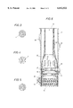
- FIG. 6 shows an embodiment of the screen according to the invention where a screen is formed in situ within the borehole.
- An expandable slotted steel tube 10 is expanded against the borehole wall 11 by pulling an expansion cone 12 upwardly through the tube 10.
- the cone 12 is suspended at the lower end of a coiled tubing 13 via which resin coated granules 14 are injected which pass via injection ports 15 just below the cone 12 into the interior of the expanding tube 10.
- a set of two disk-shaped wipers 16 is trailed behind the cone by a rod 17 which press the granules 14 out of the interior of the expanded tube 10 into the expanded slots 18 and any gaps 19 that may be present between the borehole wall 11 and the expanded tube 10.
- the granules are bonded to a permeable matrix of granules which fills the expanded slots 18 and which is also bonded to the rims of these slots 18.
- the diameter of the granules 14 is selected such that the pores between the granules 14 form sieve openings of a size suitable to prevent ingress of sandgrains into the well.
- a suitable granule size is between 0.5 and 5 mm.
- Another deformable well screen was constructed from seven layers of wire mesh woven in a plain rectangular weave pattern with respectively the following sieve opening sizes: 5000/950/162/625/325/950/5000 ⁇ m.
- the layers consisted of sheets of woven wire mesh of 350 mm long and 170 mm wide which were sintered together in a vacuum furnace between two plates of cordierite ceramic. These plates were pressed together by a 9 kg weight. The material was sintered for four hours at 1260° C. and a pressure of 10 -4 Pa. The material was allowed to cool in the furnace under vacuum.
- the stack of layers was about 9 mm thick. It was then rolled in a rolling mill to a thickness of 5 mm in one pass and sintered for a further four hours under the same conditions.
- the sintered plate was subsequently cut to a length of 310 mm and placed in a 3-roll bending machine with the 170 mm edge parallel to the roll axis and rolled to make a tube of about 100 mm diameter and 170 mm long.
- the layers with the sieve opening sizes of 162 and 325 ⁇ m acted principally as the filter layers whereas the other layers, viz those with sieve opening sizes of 625,950 and 5000 ⁇ m acted essentially as protective layers.
- a short length of a tubular sieve plate was axially compressed between platens in a press to reduce its length by 10%.
- the tube walls showed incipient buckles. No obvious changes in sieve opening size were found in a visual inspection.
- the weight of the sand recovered from the cell after the test was 9 g less. It was concluded from this test that the screen stabilized the sand sufficiently to prevent significant migration of the fine sand. Further the screen was not plugged to the extent that a significant increase in pressure drop resulted.
- the weaving patterns and wire gauges in the various layers can be selected to give the desired combination of strength and compliance in radial, circumferential and longitudinal directions so that the screen can be made as a self supporting tube which can be reeled from a drum into the well and then expanded downhole.
- the predominant weaving pattern has its warp axis parallel to the tube axis and the warp threads are bent over and under the weft threads, while the latter are relatively undistorted (as for example in reversed plain Dutch weave or reversed Dutch twill) then the yield strain in longitudinal bending will be relatively high but at relatively low stress, and the tube can be easily bent; while if the weft threads are bent and the warp threads straight (plain Dutch weave or Dutch twill) the tube can be more easily expanded or reduced in diameter.
- a square mesh weave will be deformed to a diamond pattern as a result of any deformation causing length or diameter changes, and the sieve aperture will only change slightly and by a predictable amount. If two layers of the fine mesh are separated by coarse mesh, sand eroding the first layer will accumulate in the space between the two layers and offer some protection against erosion to the second layer, not only by forming a barrier but also by locally reducing the permeability and hence the flow.
- the outermost fine mesh has a smaller sieve opening size than the next fine layer, then any material which passes through the outer fine layer may also pass through subsequent fine layers, reducing the tendency of the screen to internal plugging.
- the sieve opening size of the outermost filter layer is at least two times smaller than any of the other filter and protective layers.
- Yet another deformable well screen was made of a non-woven needlefelt consisting of aramid fibers which is marketed by the company Duflot under the trademark "KEVLAR" EA 205.
- the needlefelt was 4 mm thick, had a weight of 400 g/m 2 and was manufactured by needle punching.
- a needlefelt sheet was brought into a tubular shape and the engaging ends of the sheet were stitched together.
- the thus formed tubular screen was then arranged around an expandable slotted tube which initially had an internal diameter of 38 mm.
- the tube was subsequently expanded to an internal diameter of 80 mm. Before and after the expansion the wall thickness of the tube was 5 mm.
- the force required to pull a cone through the tube in order to expand the tube and screen assembly was 30 KN. This is 6 KN more than the force required for expansion of the expandable slotted tube alone.
- the expansion of the screen did not cause any damage to the needlefelt or to the stitches.
- the thickness of the needlefelt was reduced by 37.5%.
- the expanded tube and screen assembly had a length of 285 mm and was placed in a tubular container with a 30 mm thick annular layer of sand around the screen.
- the sand was 0-0.1 mm sand from a hydrocarbon well in Pekela, the Netherlands.
- the fluid pressure inside the tube was about 2.6 bar and the fluid pressure at the injection point was about 2.7 bar.
- the longevity of the needlefelt screen was tested by clamping it between steel plates with circular holes of various sizes.
- the steel plates were located such that the corresponding holes in the respective plates were co-axial.
- the plates with the needlefelt exposed at the location of the holes were then sandblasted for substantial periods.
- a needlefelt or other geotextile fabric is suitable for use as a deformable sandscreen. It was also concluded that such a screen can be made and installed in a cost effective manner by arranging a tubular fabric layer between two perforated co-axial pipes. Such an assembly of fabric layer and pipes can be reeled on a drum and transported to the well site, where the assembly is reeled from the drum into the well.
- the fabric layer may consist of an elongate strip which is wound helically around the inner perforated pipe such that adjacent windings of the strip at least partly overlap each other.
- the above assembly is particularly attractive if a screen of substantial length is to be installed in a compacting reservoir.
- a tubular needlefelt or other fabric layer is arranged between a pair of co-axial expandable slotted tubes.
- the fabric may also consist of a strip which is wound helically around the inner expandable tube such that a substantial overlap exists between adjacent windings of the strip before expansion of the tubes.
- the overlap is in such case selected sufficiently large that after expansion of the assembly at least some overlap remains between adjacent windings of the fabric strip.
- the screen comprises a tubular screen in which axial slots are present, which slots are regularly distributed in a staggered partly overlapping pattern over the surface of the screen.
- the tested screen was made of a nickel tube which had before expansion an internal diameter of about 145 mm and a wall thickness of 0.66 mm.
- the slots each had a length of about 3.5 mm and a width of 0.15 mm before expansion.
- the slots were pitched 5 per 24.5 mm longitudinally and 17 per 24.5 mm circumferentially, the longitudinal axis of the slots being parallel to the tube.
- One millimeter thick steel protective expandable slotted tubes were co-axially arranged within and around the screen.
- the protective tubes each comprised slots having before expansion a length of about 20 mm and a width of about 2.2 mm.
- the slots in these protective tubes were pitched at 24 mm longitudinally and 4.2 mm circumferentially.
- a 2 m long assembly of the nickel sand screen and steel protective screen was arranged within a steel casing having an internal diameter of about 160 mm and in which nine inspection holes having a diameter of about 30 mm were present.
- the assembly was expanded against the inner wall of the casing by pulling a cone through the assembly.
- Visual examination of the assembly demonstrated a tight fit between the assembly and casing and a substantially uniform expansion of the protective tubes and the nickel sand screen.
- the slots of the nickel sand screen had-opened up to a diamond shape and the smallest width of the slots was between 0.3 and 0.4 mm. It was concluded that small variations in the slot widths were due to slight variations in the exact amount of expansion and that these variations were within acceptable limits.
- a flow test was carried out during which tap water was allowed to flow via three inspection holes through the screen at rates of between 8 and 10 liters per minute. During the test the pressure drop across the screen remained between 0.1 and 0.2 bar.
Abstract
A deformable well screen for preventing migration of solid particles into a hydrocarbon production well is disclosed, the screen including at least one substantially tubular filter layer of which the sieve opening size remains fairly constant during or after expansion and/or other deformation of the screen. Optionally the screen also includes a series of circumferentially scaled filter segments that are arranged around an expandable slotted tube, an expandable slotted tube of which the slots are filled with resin coated granules, an expandable slotted tube with micro-slots, an assembly of woven metal wire screens that are sintered together and/or a synthetic geotextile fabric.
Description
This is a division of application Ser. No. 08/745,391 filed Nov. 8, 1996, now U.S. Pat. No. 5,901,789 the entire disclosure of which is hereby incorporated by reference.
The invention relates to a well screen for preventing migration of solid particles, such as sand and other formation minerals, gravel and/or proppant, into a hydrocarbon production well. More particularly, the invention relates to a well screen comprising at least one substantially tubular filter layer of which the sieve opening size is tailored to the size of particles that are to be blocked by the screen.
UK patent specification 2,115,040 discloses a wellbore screen. This screen may include outer and/or inner protective layers which are co-axial to the filter layer and which have a much larger sieve opening size than the filter layer or layers.
A problem encountered with the screen of UK patent specification '040 is that woven metal wire and other filter sheets are fragile and can be easily squeezed and damaged during installation and use. Only a minor deformation of the filter sheet may already result in variation of the sieve opening which may hamper a proper performance of the screen.
Furthermore sand screens of the known type are typically made in a flat or tubular shape and are designed to remain in their original shape without substantial deformation during and/or after installation. However, in boreholes with an irregular surface and/or sharp bends this requires the use of a screen with a much smaller diameter than that of the wellbore. Such use of a small diameter screen will result in high fluid flowrates through the sieve openings of the screen, strong wear of the screen and an increased risk of plugging of the screen and of collapse of the borehole.
It is an object of the invention to alleviate the problems.
The screen according to the invention thereto is deformable such that it can be expanded, bent, compressed and/or fluidized during installation of the screen within a wellbore and that any variation of the sieve opening size of the screen as a result of such deformation remains within predetermined limits.
Preferably the screen is expandable downhole to such a size that it, or a surrounding protective layer, can be set at least partly against the surrounding formation. At locations, such as washouts and doglegs, where the borehole wall is so irregular that still a gap would remain around the expanded screen a resin impregnated gravel could be placed in the gap to ensure a continuous mechanical contact between the screen and formation.
Optionally the screen according to the invention is arranged around an expandable slotted tube which induces the internal diameter of the screen to be increased during installation of the screen and tube assembly in a wellbore while the variation in sieve opening size of each filter layer of the screen as a result of such expansion of the screen is less than fifty per cent.
A suitable expandable slotted tube for use with the screen is disclosed in the specification of international patent application PCT/EP 93/01460.
In a preferred embodiment the screen according to the invention comprises a series of scaled filter sheets which are arranged around an expandable slotted carrier tube and which, when seen in a circumferential direction, are connected at one edge to said tube and at another edge at least partly overlap an adjacent filter sheet. Optionally, the scaled filter sheets are made ofba flexible permeable material which is selected from the group of a perforated metal plate, a metal plate comprising an array of substantially tangential slots, sintered woven metal wires and a synthetic fabric.
In another preferred embodiment the screen according to the invention comprises an expandable slotted tube of which the slots and any gaps between the tube and borehole wall have been filled in situ with granules that are bonded to each other and to the rims of the slots by a bonding agent such that pore openings of a selected size remain between the granules.
In the above embodiments the slotted tube can be expanded to a diameter which may be 50% larger than the diameter of the unexpanded tube. The sieve opening size of the screen remains substantially unaffected by such large expansion although the scaled filter sheets may be stretched in a circumferential direction as a result of frictional forces and deformed slightly by the axial contraction of the slotted carrier tube during the expansion process.
In a suitable embodiment the screen according to the invention comprises
at least one tubular filter layer which is made of a woven metal wire screen; and
an outer protective layer which co-axially surrounds the filter layer or layers and an inner protective layer which is fitted co-axially within the protective layer or layers, which protective layers comprise each a woven metal wire screen having a larger sieve opening size and wire thickness than at least one of the filter layers, and wherein the filter and protective layers are sintered together.
A principal advantage of sintering the various layers of woven metal wire screen together is that it produces a screen having a section modulus which is greater than the sum of section moduli of the individual layers. This results in a robust screen of which the sieve size does not change significantly during or after deformation which make the screen coilable around a drum and installable into a well by reeling the screen from the drum.
Optionally at least one filter layer comprises wires which are oriented in a substantially helical weaving pattern relative to a central axis of the tubular screen.
It has been found that if said pitch angle is approximately 45° then local elongation and/or shortening caused by expansion, compression and/or bending of the tubular screen then a square mesh sieve will be deformed to a diamond pattern, and the sieve opening will only change slightly and by a predictable amount.
A tubular screen having a helical weaving pattern can be conveniently manufactured from sheets or strips having the wires substantially parallel and normal to the edges, by forming those sheets or strips into a helically wound tubular shape having abutting edges, and gelding the abutting edges together, as is done for example for helically welded metal tubes.
It is observed that SU patent specification 1,066,628 discloses that a screen can be made by scrolling six layers of metal filtration cloth around a perforated metal tube and then sintering the pack. However, in the known screen the various layers are made of the same cloth. This will generally cause the wires of adjacent layers to partly block the sieve openings of adjacent layers which will reduce the effective sieve opening in a rather irregular and unpredictable way.
Other screens are disclosed in U.S. Pat. Nos. 2,858,894 and 3,087,560 and in a sales brochure of Haver and Boecker concerning screens sold under the trademark "POROPLATE".
In an alternative embodiment of the screen according to the invention the screen comprises at least one filter layer which is substantially made of a fabric, such as a needlefelt. Suitably the needlefelt comprises a material selected from the group of steel wires and synthetic fibers. Optionally the synthetic fibers are selected from the group of aramid fibers and "CARILON" polymer fibers which have a high chemical resistance. "CARILON" polymer is a linear alternating copolymer of carbon monoxide and one or more olefinically unsaturated compounds. European patent specifications Nos. 360,358 and 310,171 disclose methods for the manufacture of fibers of this polymer by gel and melt spinning, respectively. Preferably the filter layer comprises an elongate fabric strip which is wound in an overlapping helical pattern into a tubular shape, whereby adjacent windings have an overlap of between 10% and 90%, preferably about 50%.
It is observed that international patent application PCT/EP/01460 discloses that two co-axial slotted liners may be placed within the wellbore such that after expansion the slots are not in line in radial direction. This non-overlapping arrangement aims to induce fluids to traverse through the liners via a zig-zag path thereby preventing sand from entering the borehole. The liners used in this prior art reference comprised axial slots having a length of at least 25 mm and a width of at least 0.7 mm.
Surprisingly it was found that instead of using the interaction between non-overlapping relatively large slots of co-axial liners to prevent inflow of sand a suitable screen may be created by using a single expandable tube having micro-slots.
Therefore, in yet another alternative embodiment of the screen according to the invention the screen comprises an expandable tubular body with micro-slots that are arranged in a staggered and overlapping pattern which slots substantially have a length less than 10 mm before expansion of the tubular body.
Preferably the micro-slots substantially have before expansion of the tubular body a length less than 5 mm and a width less than 0.3 mm.
A principal advantage of the use of a single expandable sand-screen with micro-slots over the use of co-axial liners with non-overlapping relatively large slots is that it generates a screen with a more regular substantially diamond-shaped sieve opening size after expansion.
Suitably the expandable tubular body with micro-slots is made of nickel and has a wall thickness which is less than 1 mm. In order to protect such a fragile body from damage during and after installation it is preferred to arrange the body co-axially between two conventional expandable slotted liners having larger slots and a larger wall thickness than the body. Suitably these protective liners are made of steel and comprise slots having a length of at least 15 mm and a width of at least 2 mm.
U.S. Pat. No. 1,135,809 discloses a well screen with staggered axial slots. The screen according to this prior art reference, however, is installed downhole without being subject to any significant expansion or other deformation, so that the slots remain in their original elongate shape.
The invention also relates to a method for installing a tubular well screen in a hydrocarbon production well, the method comprising arranging the screen around an expandable slotted tube, lowering the screen and tube assembly into the well, inducing the tube to expand thereby increasing the internal diameter of the screen to be increased with at least five per cent while any variation of the sieve opening size of each filter layer of the screen is less than fifty per cent.
Optionally the screen and tube assembly is wound around a drum and reeled from said drum into the well during installation.
In an alternative embodiment the method according to the invention comprises lowering an expandable slotted tube into the well, inducing the tube to expand, injecting granules coated with a bonding agent into the expanded tube and wiping the granules at least partly away from said interior into the expanded slots of the tube and any gaps that may be present between the expanded tube and the borehole wall, and allowing the bonding agent to cure. In this way a permeable matrix of bonded solid particles is formed which substantially fills the expanded slots and any gaps between the expanded tube and the borehole wall.
The coated granules may consist of resin coated granules having a diameter between 1 and 5 mm which are injected via injection parts located behind the expansion cone and a wiper set may be trailed behind the cone in order to wipe the granules from the interior of the expanded tube into the slots and any gaps surrounding the tube.
These and other features, objects and advantages of the method and screen according to the invention will become apparent from the accompanying claims, abstract and the following detailed description.
FIG. 1 shows a cross-sectional view of a segmented screen which is lowered into a well between two unexpanded slotted tubes;
FIG. 2 shows a cross-sectional view of the screen and tube assembly of FIG. 1 after expansion of the assembly;
FIG. 3 is a side view of a section of one of the filter sheets of the segmented screen of FIG. 1 and 2 shown at an enlarged scale;
FIG. 4 is a side view of a section of the unexpanded slotted carrier and protective tube of FIG. 1 shown at an enlarged scale;
FIG. 5 is a side view of a section of the expanded carrier and protective tube of FIG. 2 shown at an enlarged scale; and
FIG. 6 is a schematic longitudinal sectional view of an expanding slotted tube where resin coated granules are wiped into the slots to form, after curing of the resin, a sandscreen.
Referring now to FIG. 1 and 2 there is shown a borehole 1 passing through an underground hydrocarbon bearing formation 2.
An assembly of an expandable slotted carrier tube 3, a well screen comprising four scaled perforated filter sheets 4 and an expandable slotted protective tube 5 has been lowered into the borehole 1.
Each filter sheet 4 is connected near one edge to the carrier tube 3 by a lug 6 such that at an opposite edge it overlaps an adjacent sheet 4.
The lugs 6 permit the filter sheets 4 to move axially with respect to the carrier tube 3 and in that way to enable the axial contraction of the carrier tube 3 as a result of tangential expansion to be compensated for by axial sliding of the filter sheets 4 over the carrier tube.
In FIG. 1 the assembly is in an unexpanded form so that the slots 7 of the two slotted tubes 3 and 5 have an elongate longitudinal shape and a constant width, when seen in circumferential direction as shown in FIG. 4, the filter sheets 4 in a longitudinal direction the sheets may also be wrapped helically around the carrier tube 3 at such pitch angle that the sheet will contract during the expansion in longitudinal direction in substantially the same way as the slotted tube 3.
During the expansion process adjacent filter sheets 4 will slide relative to each other and the sheets 4 will also slide relative to the inner wall of the protective tube 5.
In the embodiment shown the sheets 4 are made of a perforated nickel foil which is a low friction material.
In order to further reduce friction during expansion the filter sheets 4 may comprise substantially tangential slots instead of the circular perforations shown in FIG. 3. The width of such tangential slots will not change significantly during expansion of the assembly within the borehole 1.
Instead of using a nickel foil for the filter sheets 4 these sheets may also be made of another material, such as a sintered woven wire mesh and a synthetic fabric which are described in more detail elsewhere in this specification.
Instead of using a slotted steel protective tube 5 around the filter sheets 4 any other expandable and permeable protective tubular body may be used, such as a knitted geotextile sock or a scrolled perforated metal sheet. Instead of using a plurality of filter sheets which each only partly surround the carrier tube 3 also a single scrolled filter sheet may be used which is not secured. As an alternative to using lugs 6 for connecting the filter sheets 4 to the carrier tube 3, the sheets 4 may be spot welded or connected by other mechanical fasteners to the carrier tube.
In FIG. 2 the assembly is shown in an expanded form so that the slots 7 of the slotted tubes 3 and 5 have a diamond shape as can be seen in FIG. 5. Expansion of the assembly may be accomplished by moving an expansion cone through the steel carrier tube 3 as described in international patent application PCT/EP93/01460, whereby the expansion of the carrier tube also induces the outer tube 5 to expand until it substantially engages the borehole wall.
During the expansion process overlap between adjacent filter sheets 4 is reduced, but the circumferential length of the scaled sheets 4 is selected sufficiently large that still at least some overlap remains after the expansion.
As illustrated in FIG. 3 the filter sheets 4 consist of perforated plates and the width of the perforations remains substantially the same during and after the expansion process. However, the carrier tube 3 will contract slightly in longitudinal direction as a result of the expansion process. Therefore it is preferred to arrange the lugs 6 within slots which permit the lugs 6 to slide in longitudinal direction relative to the carrier tube 3. However instead of using lugs the front edges of the filter sheets 4 may also be secured to the carrier tube 3 by spot welding. In such case this may result in some longitudinal compaction of the front edges of the filter sheets during the expansion process if these front edges have a longitudinal orientation. However, alternatively the front edges of the filter sheets 4 may have a helical orientation relative to the carrier tube 3. In such case one or more filter sheets 4 may be wrapped helically around the carrier tube 3 such that opposite edges of the filter sheet overlap each other both in the unexpanded and the expanded position of the carrier tube 3.
FIG. 6 shows an embodiment of the screen according to the invention where a screen is formed in situ within the borehole. An expandable slotted steel tube 10 is expanded against the borehole wall 11 by pulling an expansion cone 12 upwardly through the tube 10.
The cone 12 is suspended at the lower end of a coiled tubing 13 via which resin coated granules 14 are injected which pass via injection ports 15 just below the cone 12 into the interior of the expanding tube 10. A set of two disk-shaped wipers 16 is trailed behind the cone by a rod 17 which press the granules 14 out of the interior of the expanded tube 10 into the expanded slots 18 and any gaps 19 that may be present between the borehole wall 11 and the expanded tube 10. After curing of the resin the granules are bonded to a permeable matrix of granules which fills the expanded slots 18 and which is also bonded to the rims of these slots 18. The diameter of the granules 14 is selected such that the pores between the granules 14 form sieve openings of a size suitable to prevent ingress of sandgrains into the well. For most sandgrain sizes a suitable granule size is between 0.5 and 5 mm.
Another deformable well screen was constructed from seven layers of wire mesh woven in a plain rectangular weave pattern with respectively the following sieve opening sizes: 5000/950/162/625/325/950/5000 μm.
These layers were sintered together in a vacuum to form a plate, which was then rolled into the form of a tube and seam welded.
The layers consisted of sheets of woven wire mesh of 350 mm long and 170 mm wide which were sintered together in a vacuum furnace between two plates of cordierite ceramic. These plates were pressed together by a 9 kg weight. The material was sintered for four hours at 1260° C. and a pressure of 10-4 Pa. The material was allowed to cool in the furnace under vacuum.
After the sintering procedure the stack of layers was about 9 mm thick. It was then rolled in a rolling mill to a thickness of 5 mm in one pass and sintered for a further four hours under the same conditions.
The sintered plate was subsequently cut to a length of 310 mm and placed in a 3-roll bending machine with the 170 mm edge parallel to the roll axis and rolled to make a tube of about 100 mm diameter and 170 mm long.
The seam was then brazed. However, if desired, it would have been possible to weld the seam. In the thus created tubular screen the layers with the sieve opening sizes of 162 and 325 μm acted principally as the filter layers whereas the other layers, viz those with sieve opening sizes of 625,950 and 5000 μm acted essentially as protective layers. The filter layer with the finest sieve opening size, i.e. 162 μm, surrounded the filter layer with the coarser sieve opening size, i.e. 325 μm, to reduce sand accumulation within the screen.
The following tests were carried out with sintered woven wire sieve plates according to the invention.
A short length of a tubular sieve plate was axially compressed between platens in a press to reduce its length by 10%. The tube walls showed incipient buckles. No obvious changes in sieve opening size were found in a visual inspection. The length changes in the finest mesh accommodated by bulging outwards between the wires of the coarser mesh, with apparent retention of weave pattern and sieve opening dimensions.
Furthermore a disc of sintered mesh was placed in a 0.5 m long cell, 50 mm diameter, containing 1500 g sand from a hydrocarbon fluid production well in Uiterburen, the Netherlands. Air at 100 bar was flowed through the sand bed and the screen for a week at a nominal velocity through the screen of 5 m/s. The pressure drop over sand bed and screen remained constant at 3 bar.
The weight of the sand recovered from the cell after the test was 9 g less. It was concluded from this test that the screen stabilized the sand sufficiently to prevent significant migration of the fine sand. Further the screen was not plugged to the extent that a significant increase in pressure drop resulted.
It was also concluded that the combination of protective layers having a coarse mesh and made from thick wire with filter layers with fine mesh that are sintered together creates a robust structure with a fine sieve size. Sintering the various layers together produces a screen having a section modulus which is greater than the sum of section moduli of the individual layers.
The weaving patterns and wire gauges in the various layers can be selected to give the desired combination of strength and compliance in radial, circumferential and longitudinal directions so that the screen can be made as a self supporting tube which can be reeled from a drum into the well and then expanded downhole.
If the predominant weaving pattern has its warp axis parallel to the tube axis and the warp threads are bent over and under the weft threads, while the latter are relatively undistorted (as for example in reversed plain Dutch weave or reversed Dutch twill) then the yield strain in longitudinal bending will be relatively high but at relatively low stress, and the tube can be easily bent; while if the weft threads are bent and the warp threads straight (plain Dutch weave or Dutch twill) the tube can be more easily expanded or reduced in diameter. If the warp and weft threads are at an angle of 45° to the tube axis (as in helically welded tube) then a square mesh weave will be deformed to a diamond pattern as a result of any deformation causing length or diameter changes, and the sieve aperture will only change slightly and by a predictable amount. If two layers of the fine mesh are separated by coarse mesh, sand eroding the first layer will accumulate in the space between the two layers and offer some protection against erosion to the second layer, not only by forming a barrier but also by locally reducing the permeability and hence the flow. If the outermost fine mesh has a smaller sieve opening size than the next fine layer, then any material which passes through the outer fine layer may also pass through subsequent fine layers, reducing the tendency of the screen to internal plugging. Preferably the sieve opening size of the outermost filter layer is at least two times smaller than any of the other filter and protective layers.
Yet another deformable well screen was made of a non-woven needlefelt consisting of aramid fibers which is marketed by the company Duflot under the trademark "KEVLAR" EA 205.
The needlefelt was 4 mm thick, had a weight of 400 g/m2 and was manufactured by needle punching.
A needlefelt sheet was brought into a tubular shape and the engaging ends of the sheet were stitched together. The thus formed tubular screen was then arranged around an expandable slotted tube which initially had an internal diameter of 38 mm. The tube was subsequently expanded to an internal diameter of 80 mm. Before and after the expansion the wall thickness of the tube was 5 mm. The force required to pull a cone through the tube in order to expand the tube and screen assembly was 30 KN. This is 6 KN more than the force required for expansion of the expandable slotted tube alone.
The expansion of the screen did not cause any damage to the needlefelt or to the stitches. The thickness of the needlefelt was reduced by 37.5%.
The expanded tube and screen assembly had a length of 285 mm and was placed in a tubular container with a 30 mm thick annular layer of sand around the screen. The sand was 0-0.1 mm sand from a hydrocarbon well in Pekela, the Netherlands. The sand had a permeability K=2.10 Darcy and a porosity n(p)=42.39%.
Water was pumped radially via six injection points through the annular sand pack and screen into the interior of the expanded tube and then circulated back during a period of six hours.
During the test the fluid pressure inside the tube was about 2.6 bar and the fluid pressure at the injection point was about 2.7 bar.
The water flux through the screen was 5 1/min. Throughout the test no sand was detected in the circulated water and the pressure drop across the sand pack and screen remained constant at about 0.1 bar. From the test it was concluded that the expansion of the screen had caused no significant effect on the performance of the screen as a sand filter and that thus only minor variations in sieve opening size of the screen had occurred as a result of the expansion.
The test was repeated with a silt fraction of 15 μ to 63 μ, smeared onto the screen, which yielded a similar favorable result.
Further the longevity of the needlefelt screen was tested by clamping it between steel plates with circular holes of various sizes. The steel plates were located such that the corresponding holes in the respective plates were co-axial. The plates with the needlefelt exposed at the location of the holes were then sandblasted for substantial periods.
No damage to the needlefelt screen was observed after the test for the holes smaller than 5 mm diameter.
It was concluded from the various tests that a needlefelt or other geotextile fabric is suitable for use as a deformable sandscreen. It was also concluded that such a screen can be made and installed in a cost effective manner by arranging a tubular fabric layer between two perforated co-axial pipes. Such an assembly of fabric layer and pipes can be reeled on a drum and transported to the well site, where the assembly is reeled from the drum into the well. The fabric layer may consist of an elongate strip which is wound helically around the inner perforated pipe such that adjacent windings of the strip at least partly overlap each other.
The above assembly is particularly attractive if a screen of substantial length is to be installed in a compacting reservoir.
Alternatively a tubular needlefelt or other fabric layer is arranged between a pair of co-axial expandable slotted tubes. In such case the fabric may also consist of a strip which is wound helically around the inner expandable tube such that a substantial overlap exists between adjacent windings of the strip before expansion of the tubes.
The overlap is in such case selected sufficiently large that after expansion of the assembly at least some overlap remains between adjacent windings of the fabric strip.
Reference is now made to yet another embodiment of the deformable tubular well screen according to the invention which is not illustrated. In this embodiment the screen comprises a tubular screen in which axial slots are present, which slots are regularly distributed in a staggered partly overlapping pattern over the surface of the screen. The tested screen was made of a nickel tube which had before expansion an internal diameter of about 145 mm and a wall thickness of 0.66 mm. The slots each had a length of about 3.5 mm and a width of 0.15 mm before expansion. The slots were pitched 5 per 24.5 mm longitudinally and 17 per 24.5 mm circumferentially, the longitudinal axis of the slots being parallel to the tube.
One millimeter thick steel protective expandable slotted tubes were co-axially arranged within and around the screen. The protective tubes each comprised slots having before expansion a length of about 20 mm and a width of about 2.2 mm. The slots in these protective tubes were pitched at 24 mm longitudinally and 4.2 mm circumferentially.
A 2 m long assembly of the nickel sand screen and steel protective screen was arranged within a steel casing having an internal diameter of about 160 mm and in which nine inspection holes having a diameter of about 30 mm were present.
The assembly was expanded against the inner wall of the casing by pulling a cone through the assembly. Visual examination of the assembly demonstrated a tight fit between the assembly and casing and a substantially uniform expansion of the protective tubes and the nickel sand screen. As a result of the expansion the slots of the nickel sand screen had-opened up to a diamond shape and the smallest width of the slots was between 0.3 and 0.4 mm. It was concluded that small variations in the slot widths were due to slight variations in the exact amount of expansion and that these variations were within acceptable limits.
A flow test was carried out during which tap water was allowed to flow via three inspection holes through the screen at rates of between 8 and 10 liters per minute. During the test the pressure drop across the screen remained between 0.1 and 0.2 bar.
A ten meter long version of this screen was installed and tested in an oil well in Oman. The production data show that not only does the screen control sand production without the need for gravel packing but also that the well's productivity is unimpaired compared to its productivity before installation of the screen. The screen also showed no signs of plugging over a sustained period of production.
Claims (5)
1. A deformable well screen for preventing migration of solid particles into a hydrocarbon production well, which screen comprises:
at least one substantially tubular filter layer having a sieve opening size which is tailored to the size of particles that are to be blocked by the screen,
wherein the filter layer is deformable such that it can be expanded, bent, and/or compressed during installation of the screen in a wellbore and that any variation of the sieve opening size of each filter layer as a result of such deformation remains within predetermined limits wherein the filter layer comprises an expandable slotted tube of which the slots and any gaps between the tube and borehole wall have been filled in situ with granules that are bonded to each other and to the rims of the slots by a bonding agent such that pore openings of a selected size remain between the granules.
2. The well screen of claim 1, wherein the well screen is coilable around a drum and installable into a well by reeling the screen from the drum.
3. The well screen of claim 1 wherein the screen comprises an expandable tubular body with longitudinal micro-slots that are arranged in a staggered and overlapping pattern, which micro-slots substantially have before expansion of the tubular body a length less than 10 mm.
4. The screen of claim 3 wherein the tubular body is made of nickel and the micro-slots substantially have a length less than 5 mm and a width less than 0.3 mm.
5. A method of installing a deformable well screen in a hydrocarbon production well, the method comprising the steps of:
lowering an expandable slotted tube into the well;
inducing the tube to expand and the slots to open;
injecting granules coated with a bonding agent into the expanded tube, wiping the granules substantially from the interior of the tube into the slots and any gaps between the tube and the wellbore; and
allowing the bonding agent to cure.
Priority Applications (1)
| Application Number | Priority Date | Filing Date | Title |
|---|---|---|---|
| US09/233,303 US6012522A (en) | 1995-11-08 | 1999-01-19 | Deformable well screen |
Applications Claiming Priority (4)
| Application Number | Priority Date | Filing Date | Title |
|---|---|---|---|
| EP9520308 | 1995-11-08 | ||
| EP95203038 | 1995-11-08 | ||
| US08/745,391 US5901789A (en) | 1995-11-08 | 1996-11-08 | Deformable well screen |
| US09/233,303 US6012522A (en) | 1995-11-08 | 1999-01-19 | Deformable well screen |
Related Parent Applications (1)
| Application Number | Title | Priority Date | Filing Date |
|---|---|---|---|
| US08/745,391 Division US5901789A (en) | 1995-11-08 | 1996-11-08 | Deformable well screen |
Publications (1)
| Publication Number | Publication Date |
|---|---|
| US6012522A true US6012522A (en) | 2000-01-11 |
Family
ID=8220809
Family Applications (2)
| Application Number | Title | Priority Date | Filing Date |
|---|---|---|---|
| US08/745,391 Expired - Lifetime US5901789A (en) | 1995-11-08 | 1996-11-08 | Deformable well screen |
| US09/233,303 Expired - Lifetime US6012522A (en) | 1995-11-08 | 1999-01-19 | Deformable well screen |
Family Applications Before (1)
| Application Number | Title | Priority Date | Filing Date |
|---|---|---|---|
| US08/745,391 Expired - Lifetime US5901789A (en) | 1995-11-08 | 1996-11-08 | Deformable well screen |
Country Status (15)
| Country | Link |
|---|---|
| US (2) | US5901789A (en) |
| EP (1) | EP0859902B2 (en) |
| JP (1) | JP3825805B2 (en) |
| AU (1) | AU710745B2 (en) |
| BR (1) | BR9611456A (en) |
| CA (1) | CA2237126C (en) |
| DE (1) | DE69617258T3 (en) |
| DK (1) | DK0859902T4 (en) |
| EA (1) | EA000332B1 (en) |
| MY (1) | MY127626A (en) |
| NO (1) | NO314004B1 (en) |
| NZ (1) | NZ322015A (en) |
| OA (1) | OA10683A (en) |
| UA (1) | UA67719C2 (en) |
| WO (1) | WO1997017524A2 (en) |
Cited By (147)
| Publication number | Priority date | Publication date | Assignee | Title |
|---|---|---|---|---|
| US6263966B1 (en) * | 1998-11-16 | 2001-07-24 | Halliburton Energy Services, Inc. | Expandable well screen |
| WO2001088332A1 (en) * | 2000-05-18 | 2001-11-22 | Halliburton Energy Services, Inc. | Thin-wall expandable well screen assembly and associated fabrication methods |
| US6322109B1 (en) * | 1995-12-09 | 2001-11-27 | Weatherford/Lamb, Inc. | Expandable tubing connector for expandable tubing |
| US6328113B1 (en) | 1998-11-16 | 2001-12-11 | Shell Oil Company | Isolation of subterranean zones |
| WO2002010550A1 (en) * | 2000-07-28 | 2002-02-07 | Enventure Global Technology | Liner hanger with standoffs |
| GB2365470A (en) * | 2000-07-27 | 2002-02-20 | Halliburton Energy Serv Inc | Method and apparatus for sand control in a subterranean well |
| US6354373B1 (en) * | 1997-11-26 | 2002-03-12 | Schlumberger Technology Corporation | Expandable tubing for a well bore hole and method of expanding |
| US20020040787A1 (en) * | 1998-12-07 | 2002-04-11 | Cook Robert Lance | Forming a wellbore casing while simultaneously drilling a wellbore |
| US20020056248A1 (en) * | 1999-11-09 | 2002-05-16 | Foster-Miller, Inc. | Foldable member |
| US20020100595A1 (en) * | 1999-02-26 | 2002-08-01 | Shell Oil Co. | Flow control system for an apparatus for radially expanding tubular members |
| US6431282B1 (en) | 1999-04-09 | 2002-08-13 | Shell Oil Company | Method for annular sealing |
| US20020129935A1 (en) * | 2000-05-05 | 2002-09-19 | Halliburton Energy Services, Inc. | Expandable well screen |
| US6454013B1 (en) * | 1997-11-01 | 2002-09-24 | Weatherford/Lamb, Inc. | Expandable downhole tubing |
| US6454493B1 (en) * | 1998-10-29 | 2002-09-24 | Shell Oil Company | Method for transporting and installing an expandable steel tubular |
| US6470966B2 (en) | 1998-12-07 | 2002-10-29 | Robert Lance Cook | Apparatus for forming wellbore casing |
| US6478092B2 (en) | 2000-09-11 | 2002-11-12 | Baker Hughes Incorporated | Well completion method and apparatus |
| US6478091B1 (en) | 2000-05-04 | 2002-11-12 | Halliburton Energy Services, Inc. | Expandable liner and associated methods of regulating fluid flow in a well |
| WO2003004819A2 (en) * | 2001-07-06 | 2003-01-16 | Enventure Global Technology | Liner hanger |
| US20030019180A1 (en) * | 1999-11-09 | 2003-01-30 | Warren Peter A. | Foldable member |
| US20030024708A1 (en) * | 1998-12-07 | 2003-02-06 | Shell Oil Co. | Structral support |
| WO2003012254A1 (en) * | 2001-07-30 | 2003-02-13 | Weatherford/Lamb, Inc. | Sintered wellscreen |
| US20030047880A1 (en) * | 2001-09-07 | 2003-03-13 | Ross Colby M. | Seal and method |
| US6557640B1 (en) | 1998-12-07 | 2003-05-06 | Shell Oil Company | Lubrication and self-cleaning system for expansion mandrel |
| US6561732B1 (en) * | 1999-08-25 | 2003-05-13 | Meyer Rohr & Schacht Gmbh | Driving pipe and method for the construction of an essentially horizontal pipeline |
| US6568472B1 (en) * | 2000-12-22 | 2003-05-27 | Halliburton Energy Services, Inc. | Method and apparatus for washing a borehole ahead of screen expansion |
| US6575250B1 (en) | 1999-11-15 | 2003-06-10 | Shell Oil Company | Expanding a tubular element in a wellbore |
| US6575240B1 (en) | 1998-12-07 | 2003-06-10 | Shell Oil Company | System and method for driving pipe |
| US6604763B1 (en) | 1998-12-07 | 2003-08-12 | Shell Oil Company | Expandable connector |
| US6607032B2 (en) | 2000-09-11 | 2003-08-19 | Baker Hughes Incorporated | Multi-layer screen and downhole completion method |
| US6634431B2 (en) | 1998-11-16 | 2003-10-21 | Robert Lance Cook | Isolation of subterranean zones |
| US6640903B1 (en) | 1998-12-07 | 2003-11-04 | Shell Oil Company | Forming a wellbore casing while simultaneously drilling a wellbore |
| US6648071B2 (en) * | 2001-01-24 | 2003-11-18 | Schlumberger Technology Corporation | Apparatus comprising expandable bistable tubulars and methods for their use in wellbores |
| US20030222455A1 (en) * | 1999-04-26 | 2003-12-04 | Shell Oil Co. | Expandable connector |
| US6659179B2 (en) * | 2001-05-18 | 2003-12-09 | Halliburton Energy Serv Inc | Method of controlling proppant flowback in a well |
| US20040003927A1 (en) * | 2002-04-25 | 2004-01-08 | Wayne Rudd | Expandable downhole tubular |
| US20040007829A1 (en) * | 2001-09-07 | 2004-01-15 | Ross Colby M. | Downhole seal assembly and method for use of same |
| US20040017081A1 (en) * | 2002-07-06 | 2004-01-29 | Simpson Neil Andrew Abercrombie | Coupling tubulars |
| US20040026313A1 (en) * | 2002-08-09 | 2004-02-12 | Arlon Fischer Todd Kenneth | Multi-micron, multi-zoned mesh, method of making and use thereof |
| US6695054B2 (en) | 2001-01-16 | 2004-02-24 | Schlumberger Technology Corporation | Expandable sand screen and methods for use |
| US6695067B2 (en) | 2001-01-16 | 2004-02-24 | Schlumberger Technology Corporation | Wellbore isolation technique |
| US20040055758A1 (en) * | 2002-09-23 | 2004-03-25 | Brezinski Michael M. | Annular isolators for expandable tubulars in wellbores |
| US20040055760A1 (en) * | 2002-09-20 | 2004-03-25 | Nguyen Philip D. | Method and apparatus for forming an annular barrier in a wellbore |
| US6712154B2 (en) | 1998-11-16 | 2004-03-30 | Enventure Global Technology | Isolation of subterranean zones |
| US6712151B2 (en) * | 2001-04-06 | 2004-03-30 | Weatherford/Lamb, Inc. | Tubing expansion |
| US6722443B1 (en) * | 1998-08-08 | 2004-04-20 | Weatherford/Lamb, Inc. | Connector for expandable well screen |
| US6732806B2 (en) | 2002-01-29 | 2004-05-11 | Weatherford/Lamb, Inc. | One trip expansion method and apparatus for use in a wellbore |
| US20040104575A1 (en) * | 2002-09-13 | 2004-06-03 | Peter Ellington | Expandable coupling |
| US6745845B2 (en) | 1998-11-16 | 2004-06-08 | Shell Oil Company | Isolation of subterranean zones |
| US20040108119A1 (en) * | 2002-12-06 | 2004-06-10 | Maguire Patrick G. | Wire lock expandable connection |
| US20040113428A1 (en) * | 2002-09-25 | 2004-06-17 | Macaulay Iain Cameron | Expandable connection |
| US20040131812A1 (en) * | 2002-10-25 | 2004-07-08 | Metcalfe Paul David | Downhole filter |
| US20040135370A1 (en) * | 2002-09-17 | 2004-07-15 | Evans Jason David | Tubing connection arrangement |
| US6769484B2 (en) | 2002-09-03 | 2004-08-03 | Jeffrey Longmore | Downhole expandable bore liner-filter |
| US6789822B1 (en) * | 1997-03-21 | 2004-09-14 | Weatherford/Lamb, Inc. | Expandable slotted tubing string and method for connecting such a tubing string |
| US20040182582A1 (en) * | 2001-07-18 | 2004-09-23 | Bosma Martin Gerard Rene | Method of sealing an annulus |
| US20040182569A1 (en) * | 1998-12-07 | 2004-09-23 | Shell Oil Co. | Apparatus for expanding a tubular member |
| US20040194278A1 (en) * | 2003-03-06 | 2004-10-07 | Lone Star Steel Company | Tubular goods with expandable threaded connections |
| US20040216506A1 (en) * | 2003-03-25 | 2004-11-04 | Simpson Neil Andrew Abercrombie | Tubing expansion |
| US6817633B2 (en) | 2002-12-20 | 2004-11-16 | Lone Star Steel Company | Tubular members and threaded connections for casing drilling and method |
| US20040228679A1 (en) * | 2003-05-16 | 2004-11-18 | Lone Star Steel Company | Solid expandable tubular members formed from very low carbon steel and method |
| US20040231839A1 (en) * | 2003-05-22 | 2004-11-25 | Peter Ellington | Thread integrity feature for expandable connections |
| US20040231855A1 (en) * | 2001-07-06 | 2004-11-25 | Cook Robert Lance | Liner hanger |
| US20040231858A1 (en) * | 1999-07-09 | 2004-11-25 | Kevin Waddell | System for lining a wellbore casing |
| US6823937B1 (en) | 1998-12-07 | 2004-11-30 | Shell Oil Company | Wellhead |
| US20040251034A1 (en) * | 1999-12-03 | 2004-12-16 | Larry Kendziora | Mono-diameter wellbore casing |
| US20040251035A1 (en) * | 2001-04-06 | 2004-12-16 | Simpson Neil Andrew Abercrombie | Hydraulically assisted tubing expansion |
| US20050022465A1 (en) * | 1999-11-09 | 2005-02-03 | Warren Peter A. | Flexible, deployment rate damped hinge |
| US20050028988A1 (en) * | 1998-11-16 | 2005-02-10 | Cook Robert Lance | Radial expansion of tubular members |
| US20050045324A1 (en) * | 1998-11-16 | 2005-03-03 | Cook Robert Lance | Radial expansion of tubular members |
| US20050056433A1 (en) * | 2001-11-12 | 2005-03-17 | Lev Ring | Mono diameter wellbore casing |
| US20050087337A1 (en) * | 2000-09-18 | 2005-04-28 | Shell Oil Company | Liner hanger with sliding sleeve valve |
| US20050110217A1 (en) * | 2003-11-25 | 2005-05-26 | Baker Hughes Incorporated | Swelling layer inflatable |
| US20050121232A1 (en) * | 1998-12-22 | 2005-06-09 | Weatherford/Lamb, Inc. | Downhole filter |
| US20050126779A1 (en) * | 2003-12-10 | 2005-06-16 | The Cavins Corporation | Seamless woven wire sintered well screen |
| US20050126776A1 (en) * | 2003-12-10 | 2005-06-16 | Russell Thane G. | Wellbore screen |
| US20050138790A1 (en) * | 2000-10-02 | 2005-06-30 | Cook Robert L. | Method and apparatus for forming a mono-diameter wellbore casing |
| US20050150098A1 (en) * | 2003-06-13 | 2005-07-14 | Robert Lance Cook | Method and apparatus for forming a mono-diameter wellbore casing |
| US20050155773A1 (en) * | 2004-01-21 | 2005-07-21 | Schlumberger Technology Corporation | System and Method to Deploy and Expand Tubular Components Deployed Through Tubing |
| US20050173108A1 (en) * | 2002-07-29 | 2005-08-11 | Cook Robert L. | Method of forming a mono diameter wellbore casing |
| US20050173130A1 (en) * | 2002-08-23 | 2005-08-11 | Baker Hughes Incorporated | Self-conforming screen |
| US20050184521A1 (en) * | 2003-05-22 | 2005-08-25 | Maguire Patrick G. | Tubing connector |
| US20050217866A1 (en) * | 2002-05-06 | 2005-10-06 | Watson Brock W | Mono diameter wellbore casing |
| US20050217865A1 (en) * | 2002-05-29 | 2005-10-06 | Lev Ring | System for radially expanding a tubular member |
| US20050230123A1 (en) * | 2001-12-27 | 2005-10-20 | Waddell Kevin K | Seal receptacle using expandable liner hanger |
| US20050230124A1 (en) * | 1998-12-07 | 2005-10-20 | Cook Robert L | Mono-diameter wellbore casing |
| US20050236159A1 (en) * | 2002-09-20 | 2005-10-27 | Scott Costa | Threaded connection for expandable tubulars |
| US20050236163A1 (en) * | 2001-01-17 | 2005-10-27 | Cook Robert L | Mono-diameter wellbore casing |
| US20050247453A1 (en) * | 2002-08-23 | 2005-11-10 | Mark Shuster | Magnetic impulse applied sleeve method of forming a wellbore casing |
| US20050269107A1 (en) * | 1999-12-03 | 2005-12-08 | Cook Robert L | Mono-diameter wellbore casing |
| US20060006648A1 (en) * | 2003-03-06 | 2006-01-12 | Grimmett Harold M | Tubular goods with threaded integral joint connections |
| US20060032640A1 (en) * | 2002-04-15 | 2006-02-16 | Todd Mattingly Haynes And Boone, L.L.P. | Protective sleeve for threaded connections for expandable liner hanger |
| US20060048948A1 (en) * | 1998-12-07 | 2006-03-09 | Enventure Global Technology, Llc | Anchor hangers |
| US20060054330A1 (en) * | 2002-09-20 | 2006-03-16 | Lev Ring | Mono diameter wellbore casing |
| US20060065403A1 (en) * | 2002-09-20 | 2006-03-30 | Watson Brock W | Bottom plug for forming a mono diameter wellbore casing |
| US20060065406A1 (en) * | 2002-08-23 | 2006-03-30 | Mark Shuster | Interposed joint sealing layer method of forming a wellbore casing |
| US20060087119A1 (en) * | 2004-10-26 | 2006-04-27 | Sivley Robert S Iv | Expandable threaded connection |
| US20060090902A1 (en) * | 2002-04-12 | 2006-05-04 | Scott Costa | Protective sleeve for threaded connections for expandable liner hanger |
| US20060096762A1 (en) * | 2002-06-10 | 2006-05-11 | Brisco David P | Mono-diameter wellbore casing |
| US20060108123A1 (en) * | 2002-12-05 | 2006-05-25 | Frank De Lucia | System for radially expanding tubular members |
| US20060112768A1 (en) * | 2002-09-20 | 2006-06-01 | Mark Shuster | Pipe formability evaluation for expandable tubulars |
| US20060113085A1 (en) * | 2002-07-24 | 2006-06-01 | Scott Costa | Dual well completion system |
| US20060113086A1 (en) * | 2002-09-20 | 2006-06-01 | Scott Costa | Protective sleeve for expandable tubulars |
| US20060157257A1 (en) * | 2002-08-26 | 2006-07-20 | Halliburton Energy Services | Fluid flow control device and method for use of same |
| US20060169460A1 (en) * | 2003-02-26 | 2006-08-03 | Brisco David P | Apparatus for radially expanding and plastically deforming a tubular member |
| US20060207760A1 (en) * | 2002-06-12 | 2006-09-21 | Watson Brock W | Collapsible expansion cone |
| US20060208488A1 (en) * | 2003-02-18 | 2006-09-21 | Enventure Global Technology | Protective compression and tension sleeves for threaded connections for radially expandable tubular members |
| US20060225892A1 (en) * | 2003-03-11 | 2006-10-12 | Enventure Global Technology | Apparatus for radially expanding and plastically deforming a tubular member |
| US7168485B2 (en) | 2001-01-16 | 2007-01-30 | Schlumberger Technology Corporation | Expandable systems that facilitate desired fluid flow |
| US20070039742A1 (en) * | 2004-02-17 | 2007-02-22 | Enventure Global Technology, Llc | Method and apparatus for coupling expandable tubular members |
| US20070051520A1 (en) * | 1998-12-07 | 2007-03-08 | Enventure Global Technology, Llc | Expansion system |
| US20070056743A1 (en) * | 2003-09-02 | 2007-03-15 | Enventure Global Technology | Method of radially expanding and plastically deforming tubular members |
| US20070143987A1 (en) * | 2000-10-02 | 2007-06-28 | Shell Oil Company | Method and Apparatus for Forming a Mono-Diameter Wellbore Casing |
| US20070228729A1 (en) * | 2003-03-06 | 2007-10-04 | Grimmett Harold M | Tubular goods with threaded integral joint connections |
| US20080083541A1 (en) * | 2003-01-22 | 2008-04-10 | Enventure Global Technology, L.L.C. | Apparatus For Radially Expanding And Plastically Deforming A Tubular Member |
| US20080087431A1 (en) * | 2006-10-17 | 2008-04-17 | Baker Hughes Incorporated | Apparatus and Method for Controlled Deployment of Shape-Conforming Materials |
| US20080105437A1 (en) * | 2006-11-02 | 2008-05-08 | Hill Stephen D | System and method utilizing a compliant well screen |
| US20080135252A1 (en) * | 2001-09-07 | 2008-06-12 | Shell Oil Company | Adjustable Expansion Cone Assembly |
| US20080156481A1 (en) * | 2006-12-29 | 2008-07-03 | Paulus Maria Heijnen Wilhelmus | Ceramic screen |
| US20090065206A1 (en) * | 2007-09-06 | 2009-03-12 | Thane Geoffrey Russell | Wellbore fluid treatment tubular and method |
| GB2455807A (en) * | 2007-12-22 | 2009-06-24 | Weatherford Lamb | Isolating tubing with a swellable seal |
| US20090184207A1 (en) * | 2008-01-22 | 2009-07-23 | Warren Peter A | Synchronously self deploying boom |
| US20100077594A1 (en) * | 2002-08-23 | 2010-04-01 | Baker Hughes Incorporated | Subterranean Screen Manufacturing Method |
| US7712522B2 (en) | 2003-09-05 | 2010-05-11 | Enventure Global Technology, Llc | Expansion cone and system |
| US7775290B2 (en) | 2003-04-17 | 2010-08-17 | Enventure Global Technology, Llc | Apparatus for radially expanding and plastically deforming a tubular member |
| US7819185B2 (en) | 2004-08-13 | 2010-10-26 | Enventure Global Technology, Llc | Expandable tubular |
| US7887103B2 (en) | 2003-05-22 | 2011-02-15 | Watherford/Lamb, Inc. | Energizing seal for expandable connections |
| US20110174481A1 (en) * | 2010-01-19 | 2011-07-21 | Baker Hughes Incorporated | Connector for Mounting Screen to Base Pipe without Welding or Swaging |
| US20110180271A1 (en) * | 2010-01-26 | 2011-07-28 | Tejas Research And Engineering, Lp | Integrated Completion String and Method for Making and Using |
| US20110214855A1 (en) * | 2001-01-16 | 2011-09-08 | Barrie Hart | Expandable Device for Use in a Well Bore |
| USRE42733E1 (en) | 2001-10-23 | 2011-09-27 | Halliburton Energy Services, Inc. | Wear-resistant, variable diameter expansion tool and expansion methods |
| US8261842B2 (en) | 2009-12-08 | 2012-09-11 | Halliburton Energy Services, Inc. | Expandable wellbore liner system |
| CN103277074A (en) * | 2013-05-23 | 2013-09-04 | 吉林市卓尔新型金属材料有限公司 | Foamed-nickel-based silicon alloy sand preventing device and manufacturing method thereof |
| USRE45011E1 (en) | 2000-10-20 | 2014-07-15 | Halliburton Energy Services, Inc. | Expandable tubing and method |
| US8844627B2 (en) | 2000-08-03 | 2014-09-30 | Schlumberger Technology Corporation | Intelligent well system and method |
| US20150027726A1 (en) * | 2012-03-07 | 2015-01-29 | Darcy Technologies Limited | Downhole apparatus |
| US20150068764A1 (en) * | 2013-09-12 | 2015-03-12 | Saudi Arabian Oil Company | Expandable tool having helical geometry |
| US9102018B2 (en) | 2010-06-11 | 2015-08-11 | Absolute Completion Technologies Ltd. | Wellbore fluid treatment and method |
| US9212540B2 (en) | 2010-06-11 | 2015-12-15 | Absolute Completion Technologies Ltd. | Wellbore fluid treatment and method |
| US9303493B2 (en) | 2009-05-15 | 2016-04-05 | Vast Power Portfolio, Llc | Method and apparatus for strain relief in thermal liners for fluid transfer |
| US9353584B2 (en) | 2011-09-20 | 2016-05-31 | Saudi Arabian Oil Company | Permeable lost circulation drilling liner |
| US9441464B2 (en) | 2010-05-17 | 2016-09-13 | Vast Power Portfolio, Llc | Bendable strain relief fluid filter liner, method and apparatus |
| US9988883B2 (en) | 2012-07-04 | 2018-06-05 | Absolute Completion Technologies Ltd. | Wellbore screen |
| US10000990B2 (en) | 2014-06-25 | 2018-06-19 | Shell Oil Company | System and method for creating a sealing tubular connection in a wellbore |
| US10036235B2 (en) | 2014-06-25 | 2018-07-31 | Shell Oil Company | Assembly and method for expanding a tubular element |
| WO2018200407A1 (en) * | 2017-04-27 | 2018-11-01 | Halliburton Energy Services, Inc. | Expandable elastomeric sealing layer for a rigid sealing device |
| WO2019165303A1 (en) * | 2018-02-23 | 2019-08-29 | Halliburton Energy Services, Inc. | Cemented barrier valve protection |
| US11078749B2 (en) | 2019-10-21 | 2021-08-03 | Saudi Arabian Oil Company | Tubular wire mesh for loss circulation and wellbore stability |
Families Citing this family (131)
| Publication number | Priority date | Publication date | Assignee | Title |
|---|---|---|---|---|
| US6273634B1 (en) * | 1996-11-22 | 2001-08-14 | Shell Oil Company | Connector for an expandable tubing string |
| MY119637A (en) * | 1997-04-28 | 2005-06-30 | Shell Int Research | Expandable well screen. |
| NO320593B1 (en) * | 1997-05-06 | 2005-12-27 | Baker Hughes Inc | System and method for producing formation fluid in a subsurface formation |
| FR2764935B1 (en) * | 1997-06-24 | 1999-09-10 | Drillflex | IN SITU CURABLE FLEXIBLE TUBULAR PREFORM HAVING A FILAMENT FRAME FOR THE PIPING OF A WELL OR PIPE |
| FR2765619B1 (en) * | 1997-07-01 | 2000-10-06 | Schlumberger Cie Dowell | METHOD AND DEVICE FOR COMPLETING WELLS FOR THE PRODUCTION OF HYDROCARBONS OR THE LIKE |
| GB9714651D0 (en) | 1997-07-12 | 1997-09-17 | Petroline Wellsystems Ltd | Downhole tubing |
| FR2771133B1 (en) * | 1997-11-17 | 2000-02-04 | Drillflex | DEVICE FOR PLACING A FILTERING ENCLOSURE WITHIN A WELL |
| US6390192B2 (en) * | 1998-03-31 | 2002-05-21 | Well, Well, Well, Inc. | Integral well filter and screen and method for making and using same |
| US6263972B1 (en) * | 1998-04-14 | 2001-07-24 | Baker Hughes Incorporated | Coiled tubing screen and method of well completion |
| US6315040B1 (en) | 1998-05-01 | 2001-11-13 | Shell Oil Company | Expandable well screen |
| GB2340857A (en) | 1998-08-24 | 2000-03-01 | Weatherford Lamb | An apparatus for facilitating the connection of tubulars and alignment with a top drive |
| GB2340859A (en) | 1998-08-24 | 2000-03-01 | Weatherford Lamb | Method and apparatus for facilitating the connection of tubulars using a top drive |
| GB2340858A (en) | 1998-08-24 | 2000-03-01 | Weatherford Lamb | Methods and apparatus for facilitating the connection of tubulars using a top drive |
| EP2273064A1 (en) | 1998-12-22 | 2011-01-12 | Weatherford/Lamb, Inc. | Procedures and equipment for profiling and jointing of pipes |
| EP1141518B1 (en) | 1998-12-22 | 2005-10-26 | Weatherford/Lamb, Inc. | Downhole sealing for production tubing |
| CA2365966C (en) * | 1999-04-09 | 2008-09-23 | Shell Internationale Research Maatschappij B.V. | Method of creating a wellbore in an underground formation |
| GB9921557D0 (en) * | 1999-09-14 | 1999-11-17 | Petroline Wellsystems Ltd | Downhole apparatus |
| US6598678B1 (en) * | 1999-12-22 | 2003-07-29 | Weatherford/Lamb, Inc. | Apparatus and methods for separating and joining tubulars in a wellbore |
| US6325148B1 (en) | 1999-12-22 | 2001-12-04 | Weatherford/Lamb, Inc. | Tools and methods for use with expandable tubulars |
| US6698517B2 (en) | 1999-12-22 | 2004-03-02 | Weatherford/Lamb, Inc. | Apparatus, methods, and applications for expanding tubulars in a wellbore |
| US6352111B1 (en) | 2000-01-11 | 2002-03-05 | Weatherford/Lamb, Inc. | Filter for subterranean wells |
| US6491168B1 (en) | 2000-04-23 | 2002-12-10 | J + L Fiber Services, Inc. | Pulp screen basket |
| DE60132936T2 (en) * | 2000-05-05 | 2009-02-26 | Weatherford/Lamb, Inc., Houston | Apparatus and method for producing a lateral bore |
| EG22761A (en) * | 2000-06-29 | 2003-07-30 | Shell Int Research | Method of transferring fluids through a permeable well lining |
| US7100690B2 (en) * | 2000-07-13 | 2006-09-05 | Halliburton Energy Services, Inc. | Gravel packing apparatus having an integrated sensor and method for use of same |
| US6412565B1 (en) * | 2000-07-27 | 2002-07-02 | Halliburton Energy Services, Inc. | Expandable screen jacket and methods of using same |
| GB2382607A (en) * | 2000-08-18 | 2003-06-04 | Halliburton Energy Serv Inc | Expandable coupling |
| US6431271B1 (en) * | 2000-09-20 | 2002-08-13 | Schlumberger Technology Corporation | Apparatus comprising bistable structures and methods for their use in oil and gas wells |
| CA2419806A1 (en) * | 2000-10-02 | 2002-04-11 | Robert Lance Cook | Method and apparatus for casing expansion |
| US6725934B2 (en) * | 2000-12-21 | 2004-04-27 | Baker Hughes Incorporated | Expandable packer isolation system |
| CA2432637C (en) * | 2000-12-22 | 2007-05-29 | E2Tech Limited | Method and apparatus for repair operations downhole |
| US20020088744A1 (en) * | 2001-01-11 | 2002-07-11 | Echols Ralph H. | Well screen having a line extending therethrough |
| US6662876B2 (en) * | 2001-03-27 | 2003-12-16 | Weatherford/Lamb, Inc. | Method and apparatus for downhole tubular expansion |
| GB0108384D0 (en) | 2001-04-04 | 2001-05-23 | Weatherford Lamb | Bore-lining tubing |
| US6510896B2 (en) | 2001-05-04 | 2003-01-28 | Weatherford/Lamb, Inc. | Apparatus and methods for utilizing expandable sand screen in wellbores |
| US7172027B2 (en) * | 2001-05-15 | 2007-02-06 | Weatherford/Lamb, Inc. | Expanding tubing |
| US6571871B2 (en) | 2001-06-20 | 2003-06-03 | Weatherford/Lamb, Inc. | Expandable sand screen and method for installing same in a wellbore |
| US6575714B2 (en) * | 2001-06-29 | 2003-06-10 | Peter Pace | Submersible pump and sprinkler system |
| MY135121A (en) * | 2001-07-18 | 2008-02-29 | Shell Int Research | Wellbore system with annular seal member |
| US6932161B2 (en) | 2001-09-26 | 2005-08-23 | Weatherford/Lams, Inc. | Profiled encapsulation for use with instrumented expandable tubular completions |
| US6877553B2 (en) | 2001-09-26 | 2005-04-12 | Weatherford/Lamb, Inc. | Profiled recess for instrumented expandable components |
| RU2290495C2 (en) * | 2001-10-05 | 2006-12-27 | Шелл Интернэшнл Рисерч Маатсхаппий Б.В. | Tubular system for well borehole, made with possible compression and expansion |
| US6820690B2 (en) | 2001-10-22 | 2004-11-23 | Schlumberger Technology Corp. | Technique utilizing an insertion guide within a wellbore |
| US6749024B2 (en) | 2001-11-09 | 2004-06-15 | Schlumberger Technology Corporation | Sand screen and method of filtering |
| US6719064B2 (en) | 2001-11-13 | 2004-04-13 | Schlumberger Technology Corporation | Expandable completion system and method |
| GB0128667D0 (en) * | 2001-11-30 | 2002-01-23 | Weatherford Lamb | Tubing expansion |
| US6688397B2 (en) | 2001-12-17 | 2004-02-10 | Schlumberger Technology Corporation | Technique for expanding tubular structures |
| US6681862B2 (en) | 2002-01-30 | 2004-01-27 | Halliburton Energy Services, Inc. | System and method for reducing the pressure drop in fluids produced through production tubing |
| CA2475671C (en) * | 2002-02-11 | 2008-01-22 | Baker Hughes Incorporated | Method of repair of collapsed or damaged tubulars downhole |
| US7156182B2 (en) | 2002-03-07 | 2007-01-02 | Baker Hughes Incorporated | Method and apparatus for one trip tubular expansion |
| US6854521B2 (en) | 2002-03-19 | 2005-02-15 | Halliburton Energy Services, Inc. | System and method for creating a fluid seal between production tubing and well casing |
| US6761218B2 (en) * | 2002-04-01 | 2004-07-13 | Halliburton Energy Services, Inc. | Methods and apparatus for improving performance of gravel packing systems |
| US6691780B2 (en) | 2002-04-18 | 2004-02-17 | Halliburton Energy Services, Inc. | Tracking of particulate flowback in subterranean wells |
| US6742598B2 (en) * | 2002-05-29 | 2004-06-01 | Weatherford/Lamb, Inc. | Method of expanding a sand screen |
| GB0215659D0 (en) * | 2002-07-06 | 2002-08-14 | Weatherford Lamb | Formed tubulars |
| US6932159B2 (en) | 2002-08-28 | 2005-08-23 | Baker Hughes Incorporated | Run in cover for downhole expandable screen |
| DE10239863B4 (en) * | 2002-08-29 | 2005-03-17 | Webasto Ag | Vehicle roof with a lid which can be moved backwards over the roof skin |
| GB2409480B (en) * | 2002-09-06 | 2006-06-28 | Shell Int Research | Wellbore device for selective transfer of fluid |
| US20040112605A1 (en) * | 2002-12-17 | 2004-06-17 | Nguyen Philip D. | Downhole systems and methods for removing particulate matter from produced fluids |
| US7665535B2 (en) * | 2002-12-19 | 2010-02-23 | Schlumberger Technology Corporation | Rigless one-trip system and method |
| US6863130B2 (en) * | 2003-01-21 | 2005-03-08 | Halliburton Energy Services, Inc. | Multi-layer deformable composite construction for use in a subterranean well |
| US20040144535A1 (en) * | 2003-01-28 | 2004-07-29 | Halliburton Energy Services, Inc. | Post installation cured braided continuous composite tubular |
| AU2004217540B2 (en) * | 2003-02-28 | 2008-09-04 | Baker Hughes Incorporated | Compliant swage |
| US7191842B2 (en) * | 2003-03-12 | 2007-03-20 | Schlumberger Technology Corporation | Collapse resistant expandables for use in wellbore environments |
| US6920932B2 (en) * | 2003-04-07 | 2005-07-26 | Weatherford/Lamb, Inc. | Joint for use with expandable tubulars |
| GB0315144D0 (en) | 2003-06-28 | 2003-08-06 | Weatherford Lamb | Centraliser |
| US7082998B2 (en) * | 2003-07-30 | 2006-08-01 | Halliburton Energy Services, Inc. | Systems and methods for placing a braided, tubular sleeve in a well bore |
| GB0318573D0 (en) | 2003-08-08 | 2003-09-10 | Weatherford Lamb | Tubing expansion tool |
| US7766099B2 (en) | 2003-08-26 | 2010-08-03 | Halliburton Energy Services, Inc. | Methods of drilling and consolidating subterranean formation particulates |
| US8167045B2 (en) | 2003-08-26 | 2012-05-01 | Halliburton Energy Services, Inc. | Methods and compositions for stabilizing formation fines and sand |
| US7195072B2 (en) * | 2003-10-14 | 2007-03-27 | Weatherford/Lamb, Inc. | Installation of downhole electrical power cable and safety valve assembly |
| US7066271B2 (en) * | 2003-11-24 | 2006-06-27 | Halliburton Energy Services, Inc. | Expanded downhole screen systems and method |
| WO2005056979A1 (en) * | 2003-12-08 | 2005-06-23 | Baker Hughes Incorporated | Cased hole perforating alternative |
| US20050139359A1 (en) * | 2003-12-29 | 2005-06-30 | Noble Drilling Services Inc. | Multiple expansion sand screen system and method |
| US20050173116A1 (en) | 2004-02-10 | 2005-08-11 | Nguyen Philip D. | Resin compositions and methods of using resin compositions to control proppant flow-back |
| US7211547B2 (en) | 2004-03-03 | 2007-05-01 | Halliburton Energy Services, Inc. | Resin compositions and methods of using such resin compositions in subterranean applications |
| US7299875B2 (en) | 2004-06-08 | 2007-11-27 | Halliburton Energy Services, Inc. | Methods for controlling particulate migration |
| US7757768B2 (en) | 2004-10-08 | 2010-07-20 | Halliburton Energy Services, Inc. | Method and composition for enhancing coverage and displacement of treatment fluids into subterranean formations |
| US8336625B2 (en) * | 2004-11-03 | 2012-12-25 | Halliburton Energy Services, Inc. | Fracturing/gravel packing tool with variable direction and exposure exit ports |
| US7883740B2 (en) | 2004-12-12 | 2011-02-08 | Halliburton Energy Services, Inc. | Low-quality particulates and methods of making and using improved low-quality particulates |
| US7318472B2 (en) * | 2005-02-02 | 2008-01-15 | Total Separation Solutions, Llc | In situ filter construction |
| US8011438B2 (en) * | 2005-02-23 | 2011-09-06 | Schlumberger Technology Corporation | Downhole flow control with selective permeability |
| US7673686B2 (en) | 2005-03-29 | 2010-03-09 | Halliburton Energy Services, Inc. | Method of stabilizing unconsolidated formation for sand control |
| US7318474B2 (en) | 2005-07-11 | 2008-01-15 | Halliburton Energy Services, Inc. | Methods and compositions for controlling formation fines and reducing proppant flow-back |
| US7726395B2 (en) | 2005-10-14 | 2010-06-01 | Weatherford/Lamb, Inc. | Expanding multiple tubular portions |
| GB0525410D0 (en) | 2005-12-14 | 2006-01-25 | Weatherford Lamb | Expanding Multiple Tubular Portions |
| US7819192B2 (en) | 2006-02-10 | 2010-10-26 | Halliburton Energy Services, Inc. | Consolidating agent emulsions and associated methods |
| US7926591B2 (en) | 2006-02-10 | 2011-04-19 | Halliburton Energy Services, Inc. | Aqueous-based emulsified consolidating agents suitable for use in drill-in applications |
| US8613320B2 (en) * | 2006-02-10 | 2013-12-24 | Halliburton Energy Services, Inc. | Compositions and applications of resins in treating subterranean formations |
| CA2646468C (en) * | 2006-03-10 | 2011-07-12 | Dynamic Tubular Systems, Inc. | Overlapping tubulars for use in geologic structures |
| US8069916B2 (en) * | 2007-01-03 | 2011-12-06 | Weatherford/Lamb, Inc. | System and methods for tubular expansion |
| US7934557B2 (en) | 2007-02-15 | 2011-05-03 | Halliburton Energy Services, Inc. | Methods of completing wells for controlling water and particulate production |
| US8496053B2 (en) | 2007-03-01 | 2013-07-30 | Weatherford/Lamb, Inc. | Erosional protection of fiber optic cable |
| US20090151942A1 (en) * | 2007-09-13 | 2009-06-18 | Bernardi Jr Louis Anthony | Sand control system and method for controlling sand production |
| US9004182B2 (en) * | 2008-02-15 | 2015-04-14 | Baker Hughes Incorporated | Expandable downhole actuator, method of making and method of actuating |
| CN101532378A (en) * | 2008-03-13 | 2009-09-16 | 中国石化集团胜利石油管理局钻井工艺研究院 | Expandable sand control screen pipe |
| US20100032167A1 (en) * | 2008-08-08 | 2010-02-11 | Adam Mark K | Method for Making Wellbore that Maintains a Minimum Drift |
| US7814973B2 (en) * | 2008-08-29 | 2010-10-19 | Halliburton Energy Services, Inc. | Sand control screen assembly and method for use of same |
| US7984762B2 (en) * | 2008-09-25 | 2011-07-26 | Halliburton Energy Services, Inc. | Pressure relieving transition joint |
| US7762329B1 (en) | 2009-01-27 | 2010-07-27 | Halliburton Energy Services, Inc. | Methods for servicing well bores with hardenable resin compositions |
| US8146662B2 (en) * | 2009-04-08 | 2012-04-03 | Halliburton Energy Services, Inc. | Well screen assembly with multi-gage wire wrapped layer |
| US20100258302A1 (en) * | 2009-04-08 | 2010-10-14 | Halliburton Energy Services, Inc. | Well Screen With Drainage Assembly |
| US8251138B2 (en) | 2009-04-09 | 2012-08-28 | Halliburton Energy Services, Inc. | Securing layers in a well screen assembly |
| US8550157B2 (en) | 2009-07-15 | 2013-10-08 | Baker Hughes Incorporated | Apparatus and method for controlling flow of solids into wellbores using filter media containing an array of three dimensional elements |
| US8376058B2 (en) | 2009-11-18 | 2013-02-19 | David K. Adamson | Well drilling wash down end cap and method |
| US8302696B2 (en) * | 2010-04-06 | 2012-11-06 | Baker Hughes Incorporated | Actuator and tubular actuator |
| US8291971B2 (en) | 2010-08-13 | 2012-10-23 | Halliburton Energy Services, Inc. | Crimped end wrapped on pipe well screen |
| US8851171B2 (en) * | 2010-10-19 | 2014-10-07 | Schlumberger Technology Corporation | Screen assembly |
| GB201019358D0 (en) | 2010-11-16 | 2010-12-29 | Darcy Technologies Ltd | Downhole method and apparatus |
| US8561699B2 (en) * | 2010-12-13 | 2013-10-22 | Halliburton Energy Services, Inc. | Well screens having enhanced well treatment capabilities |
| US10465486B1 (en) * | 2014-10-19 | 2019-11-05 | Ellingson Drainage, Inc. | Well screen with integrated filter or treatment media |
| US9616449B2 (en) | 2012-02-13 | 2017-04-11 | Absolute Completion Technologies Inc. | Apparatus for treating a wellbore screen and method |
| JP6149401B2 (en) * | 2012-12-28 | 2017-06-21 | 株式会社大林組 | Expansion well and construction method of expansion well |
| US9399902B2 (en) * | 2013-01-08 | 2016-07-26 | Halliburton Energy Services, Inc. | Expandable screen completion tool |
| GB201323121D0 (en) | 2013-12-30 | 2014-02-12 | Darcy Technologies Ltd | Downhole Apparatus |
| BR112017002659B1 (en) | 2014-08-13 | 2022-04-05 | Shell Internationale Research Maatschappij B.V. | Assembly and method for lowering and expanding a tubular element in a borehole. |
| US9434026B2 (en) * | 2014-10-02 | 2016-09-06 | Baker Hughes Incorporated | Subterranean screen assembly manufacturing method |
| US11585188B2 (en) | 2014-11-17 | 2023-02-21 | Terves, Llc | In situ expandable tubulars |
| US10584564B2 (en) | 2014-11-17 | 2020-03-10 | Terves, Llc | In situ expandable tubulars |
| US10100600B2 (en) | 2015-02-10 | 2018-10-16 | Saudi Arabian Oil Company | Expandable tools using segmented cylindrical sections |
| US10626707B2 (en) * | 2015-06-30 | 2020-04-21 | Halliburton Energy Services, Inc. | Flushing filter |
| US10443322B2 (en) * | 2015-12-09 | 2019-10-15 | Baker Hughes, a GE company | Protection of downhole tools against mechanical influences with a pliant material |
| RU2619615C1 (en) * | 2016-01-11 | 2017-05-17 | Акционерное общество "Новомет-Пермь" | Expandable well filter and method of its installation |
| CN106894768B (en) * | 2017-04-14 | 2019-07-05 | 中国地质调查局油气资源调查中心 | From the oil well oil-pumping tubing for removing sandstone |
| SE543053C2 (en) * | 2017-09-26 | 2020-09-29 | Good Sweden Ab | Well foundation and method for constructing a well |
| CN108222896A (en) * | 2018-01-17 | 2018-06-29 | 中国五冶集团有限公司 | For the halogen mining well structure of the salt pan of drift sand formation containing multilayer geology |
| EP3546696A1 (en) | 2018-03-26 | 2019-10-02 | Shell Internationale Research Maatschappij B.V. | String of expandable slotted tubulars and method of expanding a string of slotted tubulars |
| US10830021B2 (en) * | 2018-07-05 | 2020-11-10 | Baker Hughes, A Ge Company, Llc | Filtration media for an open hole production system having an expandable outer surface |
| EP3702581A1 (en) | 2019-02-26 | 2020-09-02 | Shell Internationale Research Maatschappij B.V. | Method of stabilizing a wall with exposed layers of clay |
| EP3760831B1 (en) * | 2019-07-03 | 2022-03-23 | 3M Innovative Properties Company | Separating device and use of a separating device |
| US11118435B2 (en) * | 2020-01-31 | 2021-09-14 | Halliburton Energy Services, Inc. | Compliant screen shroud to limit expansion |
Citations (27)
| Publication number | Priority date | Publication date | Assignee | Title |
|---|---|---|---|---|
| US261252A (en) * | 1882-07-18 | Drive-well point or strainer | ||
| US1135809A (en) * | 1914-01-21 | 1915-04-13 | Eli Jones | Well-strainer. |
| US1229437A (en) * | 1916-10-09 | 1917-06-12 | William H Foster | Strainer. |
| US1342986A (en) * | 1919-07-28 | 1920-06-08 | William H Cater | Well-screen |
| US1380182A (en) * | 1920-05-17 | 1921-05-31 | Robert J Bigelow | Well-liner clamp |
| US1514062A (en) * | 1922-05-09 | 1924-11-04 | Eugene A Reilly | Means for incasing wells |
| US2812025A (en) * | 1955-01-24 | 1957-11-05 | James U Teague | Expansible liner |
| US2843209A (en) * | 1951-12-29 | 1958-07-15 | Degen Wilhelm | Filter, especially for piped wells |
| US2858894A (en) * | 1954-06-14 | 1958-11-04 | Swan M Akeyson | Screen pipe |
| US2877852A (en) * | 1954-09-20 | 1959-03-17 | Frank J Bashara | Well filters |
| US2985241A (en) * | 1958-02-21 | 1961-05-23 | Charles W Hanslip | Well screen device |
| US3087560A (en) * | 1961-05-15 | 1963-04-30 | Clayton Mark & Company | Water well strainer |
| US3134442A (en) * | 1958-10-27 | 1964-05-26 | Pan American Petroleum Corp | Apparatus for lining wells |
| US3270817A (en) * | 1964-03-26 | 1966-09-06 | Gulf Research Development Co | Method and apparatus for installing a permeable well liner |
| US3353599A (en) * | 1964-08-04 | 1967-11-21 | Gulf Oil Corp | Method and apparatus for stabilizing formations |
| US4393932A (en) * | 1981-03-16 | 1983-07-19 | Bodine Albert G | Method and apparatus for uniformly packing gravel around a well casing or liner |
| GB2115040A (en) * | 1982-02-03 | 1983-09-01 | Ici Plc | Method of limiting sand production in wells |
| US4624319A (en) * | 1984-12-18 | 1986-11-25 | Jacques A. Van Der Borght | Method and apparatus to improve well water quality |
| US4821800A (en) * | 1986-12-10 | 1989-04-18 | Sherritt Gordon Mines Limited | Filtering media for controlling the flow of sand during oil well operations |
| EP0360358B1 (en) * | 1988-09-22 | 1992-12-23 | Shell Internationale Researchmaatschappij B.V. | Process for the preparation of thermoplastic fibres |
| EP0310171B1 (en) * | 1987-09-30 | 1993-12-01 | Shell Internationale Researchmaatschappij B.V. | Melt-spinning process |
| WO1993025800A1 (en) * | 1992-06-09 | 1993-12-23 | Shell Internationale Research Maatschappij B.V. | Method of completing an uncased section of a borehole |
| US5404954A (en) * | 1993-05-14 | 1995-04-11 | Conoco Inc. | Well screen for increased production |
| EP0674095A2 (en) * | 1994-03-11 | 1995-09-27 | Nagaoka International Corporation | Well screen with coiled element |
| WO1996000821A1 (en) * | 1994-06-30 | 1996-01-11 | Quality Tubing, Inc. | Preperforated coiled tubing |
| US5664628A (en) * | 1993-05-25 | 1997-09-09 | Pall Corporation | Filter for subterranean wells |
| US5667011A (en) * | 1995-01-16 | 1997-09-16 | Shell Oil Company | Method of creating a casing in a borehole |
Family Cites Families (24)
| Publication number | Priority date | Publication date | Assignee | Title |
|---|---|---|---|---|
| US1010954A (en) * | 1910-04-20 | 1911-12-05 | Chester Peter Adolph Rasmussen | Swage. |
| US2143072A (en) * | 1936-12-09 | 1939-01-10 | Baash Ross Tool Co | Liner |
| US2198573A (en) * | 1938-03-29 | 1940-04-23 | Texas Co | Method and apparatus for graveling wells |
| US2217370A (en) * | 1939-08-08 | 1940-10-08 | Socony Vacuum Oil Co Inc | Screen wrapped perforated liner pipe |
| US2835328A (en) * | 1954-12-10 | 1958-05-20 | George A Thompson | Well point |
| US3153451A (en) * | 1963-02-07 | 1964-10-20 | Forrest E Chancellor | Apparatus for completing a well |
| US3637010A (en) * | 1970-03-04 | 1972-01-25 | Union Oil Co | Apparatus for gravel-packing inclined wells |
| US3633674A (en) * | 1970-10-14 | 1972-01-11 | Schlumberger Technology Corp | Methods and apparatus for inhibiting the entrance of loose formation materials into a well bore |
| GB1455481A (en) * | 1974-02-23 | 1976-11-10 | Lovell G E | Well-point filter |
| GB2067425A (en) * | 1980-01-11 | 1981-07-30 | Lucas Industries Ltd | Filter elements |
| SU1066628A1 (en) * | 1982-06-21 | 1984-01-15 | Специальное Проектно-Конструкторское И Технологическое Бюро Химического И Нефтяного Машиностроения | Method of producing filter |
| US4434054A (en) * | 1982-12-20 | 1984-02-28 | Texaco Canada Resources Ltd. | Filter for separating discrete solid elements from a fluid stream |
| CH658674A5 (en) * | 1984-03-02 | 1986-11-28 | Alusuisse | CATHODE TUB FOR AN ALUMINUM ELECTROLYSIS CELL AND METHOD FOR THE PRODUCTION OF THE COMPOSITE BODIES THEREOF THE SIDE WALL. |
| SU1337512A1 (en) * | 1984-11-20 | 1987-09-15 | Среднеазиатский Научно-Исследовательский И Проектный Институт "Средазнипинефть" | Borehole filter |
| FR2584942B1 (en) * | 1985-07-19 | 1989-12-01 | Dollfus Noack Sa | HIGH-TEMPERATURE CORROSIVE GAS FILTERING FELT |
| DE3816670A1 (en) * | 1987-06-09 | 1988-12-29 | Akzo Gmbh | Dome for landfills |
| DE3887905D1 (en) * | 1988-11-22 | 1994-03-24 | Tatarskij Gni Skij I Pi Neftja | EXPANDING TOOL FOR TUBES. |
| US5088554A (en) * | 1990-10-22 | 1992-02-18 | Otis Engineering Corporation | Sintered metal sand screen |
| DE4126420C1 (en) * | 1991-08-09 | 1993-02-11 | Bergwerksverband Gmbh, 4300 Essen, De | Metallic filter element of improved mechanical stability - obtd. from chromium@-nickel@-molybdenum@-titanium@-contg. steel sheet and has round orifices or slits on inflow side, used for sepn. of particles from gases |
| US5211234A (en) * | 1992-01-30 | 1993-05-18 | Halliburton Company | Horizontal well completion methods |
| US5226581A (en) * | 1992-06-03 | 1993-07-13 | Filtration & Coating Services, Inc. | Method of retrofitting metal fiber felt in polymer filtration devices |
| MY108743A (en) * | 1992-06-09 | 1996-11-30 | Shell Int Research | Method of greating a wellbore in an underground formation |
| AU679081B2 (en) * | 1993-05-25 | 1997-06-19 | Pall Corporation | Sand screen structure |
| JP2732031B2 (en) * | 1994-04-28 | 1998-03-25 | 株式会社いすゞセラミックス研究所 | Exhaust particulate filter for diesel engine |
-
1996
- 1996-07-11 UA UA98052381A patent/UA67719C2/en unknown
- 1996-11-07 BR BR9611456A patent/BR9611456A/en not_active IP Right Cessation
- 1996-11-07 EA EA199800433A patent/EA000332B1/en not_active IP Right Cessation
- 1996-11-07 JP JP51786397A patent/JP3825805B2/en not_active Expired - Lifetime
- 1996-11-07 WO PCT/EP1996/004887 patent/WO1997017524A2/en active IP Right Grant
- 1996-11-07 AU AU75680/96A patent/AU710745B2/en not_active Expired
- 1996-11-07 EP EP96938148A patent/EP0859902B2/en not_active Expired - Lifetime
- 1996-11-07 DK DK96938148T patent/DK0859902T4/en active
- 1996-11-07 DE DE69617258T patent/DE69617258T3/en not_active Expired - Lifetime
- 1996-11-07 MY MYPI96004636A patent/MY127626A/en unknown
- 1996-11-07 NZ NZ322015A patent/NZ322015A/en not_active IP Right Cessation
- 1996-11-07 CA CA002237126A patent/CA2237126C/en not_active Expired - Lifetime
- 1996-11-08 US US08/745,391 patent/US5901789A/en not_active Expired - Lifetime
-
1998
- 1998-05-07 OA OA9800050A patent/OA10683A/en unknown
- 1998-05-07 NO NO19982087A patent/NO314004B1/en not_active IP Right Cessation
-
1999
- 1999-01-19 US US09/233,303 patent/US6012522A/en not_active Expired - Lifetime
Patent Citations (28)
| Publication number | Priority date | Publication date | Assignee | Title |
|---|---|---|---|---|
| US261252A (en) * | 1882-07-18 | Drive-well point or strainer | ||
| US1135809A (en) * | 1914-01-21 | 1915-04-13 | Eli Jones | Well-strainer. |
| US1229437A (en) * | 1916-10-09 | 1917-06-12 | William H Foster | Strainer. |
| US1342986A (en) * | 1919-07-28 | 1920-06-08 | William H Cater | Well-screen |
| US1380182A (en) * | 1920-05-17 | 1921-05-31 | Robert J Bigelow | Well-liner clamp |
| US1514062A (en) * | 1922-05-09 | 1924-11-04 | Eugene A Reilly | Means for incasing wells |
| US2843209A (en) * | 1951-12-29 | 1958-07-15 | Degen Wilhelm | Filter, especially for piped wells |
| US2858894A (en) * | 1954-06-14 | 1958-11-04 | Swan M Akeyson | Screen pipe |
| US2877852A (en) * | 1954-09-20 | 1959-03-17 | Frank J Bashara | Well filters |
| US2812025A (en) * | 1955-01-24 | 1957-11-05 | James U Teague | Expansible liner |
| US2985241A (en) * | 1958-02-21 | 1961-05-23 | Charles W Hanslip | Well screen device |
| US3134442A (en) * | 1958-10-27 | 1964-05-26 | Pan American Petroleum Corp | Apparatus for lining wells |
| US3087560A (en) * | 1961-05-15 | 1963-04-30 | Clayton Mark & Company | Water well strainer |
| US3270817A (en) * | 1964-03-26 | 1966-09-06 | Gulf Research Development Co | Method and apparatus for installing a permeable well liner |
| US3353599A (en) * | 1964-08-04 | 1967-11-21 | Gulf Oil Corp | Method and apparatus for stabilizing formations |
| US4393932A (en) * | 1981-03-16 | 1983-07-19 | Bodine Albert G | Method and apparatus for uniformly packing gravel around a well casing or liner |
| GB2115040A (en) * | 1982-02-03 | 1983-09-01 | Ici Plc | Method of limiting sand production in wells |
| US4624319A (en) * | 1984-12-18 | 1986-11-25 | Jacques A. Van Der Borght | Method and apparatus to improve well water quality |
| US4821800A (en) * | 1986-12-10 | 1989-04-18 | Sherritt Gordon Mines Limited | Filtering media for controlling the flow of sand during oil well operations |
| EP0310171B1 (en) * | 1987-09-30 | 1993-12-01 | Shell Internationale Researchmaatschappij B.V. | Melt-spinning process |
| EP0360358B1 (en) * | 1988-09-22 | 1992-12-23 | Shell Internationale Researchmaatschappij B.V. | Process for the preparation of thermoplastic fibres |
| WO1993025800A1 (en) * | 1992-06-09 | 1993-12-23 | Shell Internationale Research Maatschappij B.V. | Method of completing an uncased section of a borehole |
| US5366012A (en) * | 1992-06-09 | 1994-11-22 | Shell Oil Company | Method of completing an uncased section of a borehole |
| US5404954A (en) * | 1993-05-14 | 1995-04-11 | Conoco Inc. | Well screen for increased production |
| US5664628A (en) * | 1993-05-25 | 1997-09-09 | Pall Corporation | Filter for subterranean wells |
| EP0674095A2 (en) * | 1994-03-11 | 1995-09-27 | Nagaoka International Corporation | Well screen with coiled element |
| WO1996000821A1 (en) * | 1994-06-30 | 1996-01-11 | Quality Tubing, Inc. | Preperforated coiled tubing |
| US5667011A (en) * | 1995-01-16 | 1997-09-16 | Shell Oil Company | Method of creating a casing in a borehole |
Cited By (288)
| Publication number | Priority date | Publication date | Assignee | Title |
|---|---|---|---|---|
| US6322109B1 (en) * | 1995-12-09 | 2001-11-27 | Weatherford/Lamb, Inc. | Expandable tubing connector for expandable tubing |
| US20050029812A1 (en) * | 1997-03-21 | 2005-02-10 | Weatherford Lamb, Inc. | Expandable slotted tubing string and method for connecting such a tubing string |
| US20060107514A1 (en) * | 1997-03-21 | 2006-05-25 | Weatherford Lamb, Inc. | Expandable slotted tubing string and method for connecting such a tubing string |
| US7225523B2 (en) | 1997-03-21 | 2007-06-05 | Weatherford/Lamb, Inc. | Method for coupling and expanding tubing |
| US6789822B1 (en) * | 1997-03-21 | 2004-09-14 | Weatherford/Lamb, Inc. | Expandable slotted tubing string and method for connecting such a tubing string |
| US7124830B2 (en) | 1997-11-01 | 2006-10-24 | Weatherford/Lamb, Inc. | Methods of placing expandable downhole tubing in a wellbore |
| US6454013B1 (en) * | 1997-11-01 | 2002-09-24 | Weatherford/Lamb, Inc. | Expandable downhole tubing |
| US6920935B2 (en) | 1997-11-01 | 2005-07-26 | Weatherford/Lamb, Inc. | Expandable downhole tubing |
| US20050279514A1 (en) * | 1997-11-01 | 2005-12-22 | Weatherford/Lamb, Inc. | Expandable downhole tubing |
| US6354373B1 (en) * | 1997-11-26 | 2002-03-12 | Schlumberger Technology Corporation | Expandable tubing for a well bore hole and method of expanding |
| US20050199385A1 (en) * | 1998-08-08 | 2005-09-15 | Weatherford/Lamb, Inc. | Connector for expandable well screen |
| US6722443B1 (en) * | 1998-08-08 | 2004-04-20 | Weatherford/Lamb, Inc. | Connector for expandable well screen |
| US20040194968A1 (en) * | 1998-08-08 | 2004-10-07 | Weatherford/Lamb, Inc. | Connector for expandable well screen |
| US7140446B2 (en) | 1998-08-08 | 2006-11-28 | Weatherford/ Lamb, Inc. | Connector for expandable well screen |
| US6896057B2 (en) | 1998-08-08 | 2005-05-24 | Weatherford/Lamb, Inc. | Connector for expandable well screen |
| US6454493B1 (en) * | 1998-10-29 | 2002-09-24 | Shell Oil Company | Method for transporting and installing an expandable steel tubular |
| US20050045324A1 (en) * | 1998-11-16 | 2005-03-03 | Cook Robert Lance | Radial expansion of tubular members |
| US20050045341A1 (en) * | 1998-11-16 | 2005-03-03 | Cook Robert Lance | Radial expansion of tubular members |
| US6328113B1 (en) | 1998-11-16 | 2001-12-11 | Shell Oil Company | Isolation of subterranean zones |
| US20050077051A1 (en) * | 1998-11-16 | 2005-04-14 | Cook Robert Lance | Radial expansion of tubular members |
| US6712154B2 (en) | 1998-11-16 | 2004-03-30 | Enventure Global Technology | Isolation of subterranean zones |
| US6634431B2 (en) | 1998-11-16 | 2003-10-21 | Robert Lance Cook | Isolation of subterranean zones |
| US20030173090A1 (en) * | 1998-11-16 | 2003-09-18 | Shell Oil Co. | Lubrication and self-cleaning system for expansion mandrel |
| US6745845B2 (en) | 1998-11-16 | 2004-06-08 | Shell Oil Company | Isolation of subterranean zones |
| US6263966B1 (en) * | 1998-11-16 | 2001-07-24 | Halliburton Energy Services, Inc. | Expandable well screen |
| US20050028988A1 (en) * | 1998-11-16 | 2005-02-10 | Cook Robert Lance | Radial expansion of tubular members |
| US20080087418A1 (en) * | 1998-12-07 | 2008-04-17 | Shell Oil Company | Pipeline |
| US20070051520A1 (en) * | 1998-12-07 | 2007-03-08 | Enventure Global Technology, Llc | Expansion system |
| US20050230124A1 (en) * | 1998-12-07 | 2005-10-20 | Cook Robert L | Mono-diameter wellbore casing |
| US6561227B2 (en) | 1998-12-07 | 2003-05-13 | Shell Oil Company | Wellbore casing |
| US6758278B2 (en) | 1998-12-07 | 2004-07-06 | Shell Oil Company | Forming a wellbore casing while simultaneously drilling a wellbore |
| US20050230103A1 (en) * | 1998-12-07 | 2005-10-20 | Shell Oil Co. | Apparatus for expanding a tubular member |
| US20030024708A1 (en) * | 1998-12-07 | 2003-02-06 | Shell Oil Co. | Structral support |
| US6739392B2 (en) | 1998-12-07 | 2004-05-25 | Shell Oil Company | Forming a wellbore casing while simultaneously drilling a wellbore |
| US20040182569A1 (en) * | 1998-12-07 | 2004-09-23 | Shell Oil Co. | Apparatus for expanding a tubular member |
| US20050205253A1 (en) * | 1998-12-07 | 2005-09-22 | Shell Oil Co. | Apparatus for expanding a tubular member |
| US6604763B1 (en) | 1998-12-07 | 2003-08-12 | Shell Oil Company | Expandable connector |
| US6575240B1 (en) | 1998-12-07 | 2003-06-10 | Shell Oil Company | System and method for driving pipe |
| US7665532B2 (en) | 1998-12-07 | 2010-02-23 | Shell Oil Company | Pipeline |
| US6557640B1 (en) | 1998-12-07 | 2003-05-06 | Shell Oil Company | Lubrication and self-cleaning system for expansion mandrel |
| US6725919B2 (en) | 1998-12-07 | 2004-04-27 | Shell Oil Company | Forming a wellbore casing while simultaneously drilling a wellbore |
| US20050224225A1 (en) * | 1998-12-07 | 2005-10-13 | Shell Oil Co. | Apparatus for expanding a tubular member |
| US6631760B2 (en) | 1998-12-07 | 2003-10-14 | Shell Oil Company | Tie back liner for a well system |
| US6470966B2 (en) | 1998-12-07 | 2002-10-29 | Robert Lance Cook | Apparatus for forming wellbore casing |
| US20060048948A1 (en) * | 1998-12-07 | 2006-03-09 | Enventure Global Technology, Llc | Anchor hangers |
| US7240728B2 (en) * | 1998-12-07 | 2007-07-10 | Shell Oil Company | Expandable tubulars with a radial passage and wall portions with different wall thicknesses |
| US6640903B1 (en) | 1998-12-07 | 2003-11-04 | Shell Oil Company | Forming a wellbore casing while simultaneously drilling a wellbore |
| US6497289B1 (en) | 1998-12-07 | 2002-12-24 | Robert Lance Cook | Method of creating a casing in a borehole |
| US20030098154A1 (en) * | 1998-12-07 | 2003-05-29 | Shell Oil Co. | Apparatus for radially expanding tubular members |
| US20070012456A1 (en) * | 1998-12-07 | 2007-01-18 | Shell Oil Company | Wellbore Casing |
| US6823937B1 (en) | 1998-12-07 | 2004-11-30 | Shell Oil Company | Wellhead |
| US20020040787A1 (en) * | 1998-12-07 | 2002-04-11 | Cook Robert Lance | Forming a wellbore casing while simultaneously drilling a wellbore |
| US20050121232A1 (en) * | 1998-12-22 | 2005-06-09 | Weatherford/Lamb, Inc. | Downhole filter |
| US20060213668A1 (en) * | 1999-02-26 | 2006-09-28 | Enventure Global Technology | A Method of Coupling Tubular Member |
| US6631769B2 (en) | 1999-02-26 | 2003-10-14 | Shell Oil Company | Method of operating an apparatus for radially expanding a tubular member |
| US6684947B2 (en) | 1999-02-26 | 2004-02-03 | Shell Oil Company | Apparatus for radially expanding a tubular member |
| US6568471B1 (en) | 1999-02-26 | 2003-05-27 | Shell Oil Company | Liner hanger |
| US6631759B2 (en) | 1999-02-26 | 2003-10-14 | Shell Oil Company | Apparatus for radially expanding a tubular member |
| US6705395B2 (en) | 1999-02-26 | 2004-03-16 | Shell Oil Company | Wellbore casing |
| US20020100595A1 (en) * | 1999-02-26 | 2002-08-01 | Shell Oil Co. | Flow control system for an apparatus for radially expanding tubular members |
| US6431282B1 (en) | 1999-04-09 | 2002-08-13 | Shell Oil Company | Method for annular sealing |
| US20030222455A1 (en) * | 1999-04-26 | 2003-12-04 | Shell Oil Co. | Expandable connector |
| US20040231858A1 (en) * | 1999-07-09 | 2004-11-25 | Kevin Waddell | System for lining a wellbore casing |
| US6561732B1 (en) * | 1999-08-25 | 2003-05-13 | Meyer Rohr & Schacht Gmbh | Driving pipe and method for the construction of an essentially horizontal pipeline |
| US20050022465A1 (en) * | 1999-11-09 | 2005-02-03 | Warren Peter A. | Flexible, deployment rate damped hinge |
| US20020056248A1 (en) * | 1999-11-09 | 2002-05-16 | Foster-Miller, Inc. | Foldable member |
| US20030019180A1 (en) * | 1999-11-09 | 2003-01-30 | Warren Peter A. | Foldable member |
| US8074324B2 (en) | 1999-11-09 | 2011-12-13 | Foster-Miller, Inc. | Flexible, deployment rate damped hinge |
| US6575250B1 (en) | 1999-11-15 | 2003-06-10 | Shell Oil Company | Expanding a tubular element in a wellbore |
| US20050269107A1 (en) * | 1999-12-03 | 2005-12-08 | Cook Robert L | Mono-diameter wellbore casing |
| US20040251034A1 (en) * | 1999-12-03 | 2004-12-16 | Larry Kendziora | Mono-diameter wellbore casing |
| US6725918B2 (en) | 2000-05-04 | 2004-04-27 | Halliburton Energy Services, Inc. | Expandable liner and associated methods of regulating fluid flow in a well |
| US6478091B1 (en) | 2000-05-04 | 2002-11-12 | Halliburton Energy Services, Inc. | Expandable liner and associated methods of regulating fluid flow in a well |
| US20020129935A1 (en) * | 2000-05-05 | 2002-09-19 | Halliburton Energy Services, Inc. | Expandable well screen |
| US6457518B1 (en) | 2000-05-05 | 2002-10-01 | Halliburton Energy Services, Inc. | Expandable well screen |
| US7108062B2 (en) | 2000-05-05 | 2006-09-19 | Halliburton Energy Services, Inc. | Expandable well screen |
| US20040060695A1 (en) * | 2000-05-05 | 2004-04-01 | Halliburton Energy Services, Inc. | Expandable well screen |
| US20020178582A1 (en) * | 2000-05-18 | 2002-12-05 | Halliburton Energy Services, Inc. | Methods of fabricating a thin-wall expandable well screen assembly |
| GB2380750B (en) * | 2000-05-18 | 2004-11-24 | Halliburton Energy Serv Inc | Thin-wall expandable well screen assembly and associated fabrication methods |
| GB2380750A (en) * | 2000-05-18 | 2003-04-16 | Halliburton Energy Serv Inc | Thin-wall expandable well screen assembly and associated fabrication methods |
| WO2001088332A1 (en) * | 2000-05-18 | 2001-11-22 | Halliburton Energy Services, Inc. | Thin-wall expandable well screen assembly and associated fabrication methods |
| US6415509B1 (en) | 2000-05-18 | 2002-07-09 | Halliburton Energy Services, Inc. | Methods of fabricating a thin-wall expandable well screen assembly |
| US6619401B2 (en) * | 2000-05-18 | 2003-09-16 | Halliburton Energy Services, Inc. | Methods of completing a subterranean well |
| US6799686B2 (en) | 2000-05-18 | 2004-10-05 | Halliburton Energy Services, Inc. | Tubular filtration apparatus |
| US6941652B2 (en) * | 2000-05-18 | 2005-09-13 | Halliburton Energy Services, Inc. | Methods of fabricating a thin-wall expandable well screen assembly |
| CN1308568C (en) * | 2000-05-18 | 2007-04-04 | 哈利伯顿能源服务公司 | Thin-wall expandable well screen assembly and associated fabrication methods |
| GB2365470A (en) * | 2000-07-27 | 2002-02-20 | Halliburton Energy Serv Inc | Method and apparatus for sand control in a subterranean well |
| GB2382367A (en) * | 2000-07-28 | 2003-05-28 | Enventure Global Technology | Liner hanger with standoffs |
| GB2382367B (en) * | 2000-07-28 | 2004-09-22 | Enventure Global Technology | Coupling an expandable liner to a wellbore casing |
| WO2002010550A1 (en) * | 2000-07-28 | 2002-02-07 | Enventure Global Technology | Liner hanger with standoffs |
| US8844627B2 (en) | 2000-08-03 | 2014-09-30 | Schlumberger Technology Corporation | Intelligent well system and method |
| US6478092B2 (en) | 2000-09-11 | 2002-11-12 | Baker Hughes Incorporated | Well completion method and apparatus |
| US6607032B2 (en) | 2000-09-11 | 2003-08-19 | Baker Hughes Incorporated | Multi-layer screen and downhole completion method |
| US20050087337A1 (en) * | 2000-09-18 | 2005-04-28 | Shell Oil Company | Liner hanger with sliding sleeve valve |
| US20050150660A1 (en) * | 2000-10-02 | 2005-07-14 | Cook Robert L. | Method and apparatus for forming a mono-diameter wellbore casing |
| US20070143987A1 (en) * | 2000-10-02 | 2007-06-28 | Shell Oil Company | Method and Apparatus for Forming a Mono-Diameter Wellbore Casing |
| US20050144771A1 (en) * | 2000-10-02 | 2005-07-07 | Cook Robert L. | Method and apparatus for forming a mono-diameter wellbore casing |
| US20050144772A1 (en) * | 2000-10-02 | 2005-07-07 | Cook Robert L. | Method and apparatus for forming a mono-diameter wellbore casing |
| US20050138790A1 (en) * | 2000-10-02 | 2005-06-30 | Cook Robert L. | Method and apparatus for forming a mono-diameter wellbore casing |
| USRE45099E1 (en) | 2000-10-20 | 2014-09-02 | Halliburton Energy Services, Inc. | Expandable tubing and method |
| USRE45244E1 (en) | 2000-10-20 | 2014-11-18 | Halliburton Energy Services, Inc. | Expandable tubing and method |
| USRE45011E1 (en) | 2000-10-20 | 2014-07-15 | Halliburton Energy Services, Inc. | Expandable tubing and method |
| US6568472B1 (en) * | 2000-12-22 | 2003-05-27 | Halliburton Energy Services, Inc. | Method and apparatus for washing a borehole ahead of screen expansion |
| US6695067B2 (en) | 2001-01-16 | 2004-02-24 | Schlumberger Technology Corporation | Wellbore isolation technique |
| US7134501B2 (en) | 2001-01-16 | 2006-11-14 | Schlumberger Technology Corporation | Expandable sand screen and methods for use |
| US20110214855A1 (en) * | 2001-01-16 | 2011-09-08 | Barrie Hart | Expandable Device for Use in a Well Bore |
| US7168485B2 (en) | 2001-01-16 | 2007-01-30 | Schlumberger Technology Corporation | Expandable systems that facilitate desired fluid flow |
| US20040163819A1 (en) * | 2001-01-16 | 2004-08-26 | Johnson Craig D. | Expandable sand screen and methods for use |
| US8230913B2 (en) | 2001-01-16 | 2012-07-31 | Halliburton Energy Services, Inc. | Expandable device for use in a well bore |
| US6695054B2 (en) | 2001-01-16 | 2004-02-24 | Schlumberger Technology Corporation | Expandable sand screen and methods for use |
| US20050236163A1 (en) * | 2001-01-17 | 2005-10-27 | Cook Robert L | Mono-diameter wellbore casing |
| US6648071B2 (en) * | 2001-01-24 | 2003-11-18 | Schlumberger Technology Corporation | Apparatus comprising expandable bistable tubulars and methods for their use in wellbores |
| US7350585B2 (en) | 2001-04-06 | 2008-04-01 | Weatherford/Lamb, Inc. | Hydraulically assisted tubing expansion |
| US6712151B2 (en) * | 2001-04-06 | 2004-03-30 | Weatherford/Lamb, Inc. | Tubing expansion |
| US20040177974A1 (en) * | 2001-04-06 | 2004-09-16 | Simpson Neil Andrew Abercrombie | Tubing expansion |
| US6976536B2 (en) | 2001-04-06 | 2005-12-20 | Weatherford/Lamb, Inc. | Tubing expansion |
| US20040251035A1 (en) * | 2001-04-06 | 2004-12-16 | Simpson Neil Andrew Abercrombie | Hydraulically assisted tubing expansion |
| AU782865B2 (en) * | 2001-05-18 | 2005-09-01 | Halliburton Energy Services, Inc. | Method of controlling proppant flowback in a well |
| US6659179B2 (en) * | 2001-05-18 | 2003-12-09 | Halliburton Energy Serv Inc | Method of controlling proppant flowback in a well |
| GB2394979A (en) * | 2001-07-06 | 2004-05-12 | Eventure Global Technology | Liner hanger |
| GB2394979B (en) * | 2001-07-06 | 2005-11-02 | Eventure Global Technology | Liner hanger |
| WO2003004819A3 (en) * | 2001-07-06 | 2003-05-22 | Enventure Global Technology | Liner hanger |
| US20040238181A1 (en) * | 2001-07-06 | 2004-12-02 | Cook Robert Lance | Liner hanger |
| WO2003004819A2 (en) * | 2001-07-06 | 2003-01-16 | Enventure Global Technology | Liner hanger |
| US20040231855A1 (en) * | 2001-07-06 | 2004-11-25 | Cook Robert Lance | Liner hanger |
| US7004260B2 (en) | 2001-07-18 | 2006-02-28 | Shell Oil Company | Method of sealing an annulus |
| US20040182582A1 (en) * | 2001-07-18 | 2004-09-23 | Bosma Martin Gerard Rene | Method of sealing an annulus |
| WO2003012254A1 (en) * | 2001-07-30 | 2003-02-13 | Weatherford/Lamb, Inc. | Sintered wellscreen |
| GB2391571A (en) * | 2001-07-30 | 2004-02-11 | Weatherford Lamb | Sintered wellscreen |
| US6612481B2 (en) | 2001-07-30 | 2003-09-02 | Weatherford/Lamb, Inc. | Wellscreen |
| GB2391571B (en) * | 2001-07-30 | 2005-05-11 | Weatherford Lamb | Sintered wellscreen |
| US20040007829A1 (en) * | 2001-09-07 | 2004-01-15 | Ross Colby M. | Downhole seal assembly and method for use of same |
| US20080135252A1 (en) * | 2001-09-07 | 2008-06-12 | Shell Oil Company | Adjustable Expansion Cone Assembly |
| US20030047880A1 (en) * | 2001-09-07 | 2003-03-13 | Ross Colby M. | Seal and method |
| USRE42733E1 (en) | 2001-10-23 | 2011-09-27 | Halliburton Energy Services, Inc. | Wear-resistant, variable diameter expansion tool and expansion methods |
| US20050056433A1 (en) * | 2001-11-12 | 2005-03-17 | Lev Ring | Mono diameter wellbore casing |
| US20050056434A1 (en) * | 2001-11-12 | 2005-03-17 | Watson Brock Wayne | Collapsible expansion cone |
| US20050230123A1 (en) * | 2001-12-27 | 2005-10-20 | Waddell Kevin K | Seal receptacle using expandable liner hanger |
| US6732806B2 (en) | 2002-01-29 | 2004-05-11 | Weatherford/Lamb, Inc. | One trip expansion method and apparatus for use in a wellbore |
| US20060090902A1 (en) * | 2002-04-12 | 2006-05-04 | Scott Costa | Protective sleeve for threaded connections for expandable liner hanger |
| US7740076B2 (en) | 2002-04-12 | 2010-06-22 | Enventure Global Technology, L.L.C. | Protective sleeve for threaded connections for expandable liner hanger |
| US20060032640A1 (en) * | 2002-04-15 | 2006-02-16 | Todd Mattingly Haynes And Boone, L.L.P. | Protective sleeve for threaded connections for expandable liner hanger |
| US7918284B2 (en) | 2002-04-15 | 2011-04-05 | Enventure Global Technology, L.L.C. | Protective sleeve for threaded connections for expandable liner hanger |
| US7077196B2 (en) * | 2002-04-25 | 2006-07-18 | Weatherford/Lamb, Inc. | Expandable downhole tubular and method of use |
| US20040003927A1 (en) * | 2002-04-25 | 2004-01-08 | Wayne Rudd | Expandable downhole tubular |
| US20050217866A1 (en) * | 2002-05-06 | 2005-10-06 | Watson Brock W | Mono diameter wellbore casing |
| US20050217865A1 (en) * | 2002-05-29 | 2005-10-06 | Lev Ring | System for radially expanding a tubular member |
| US20060096762A1 (en) * | 2002-06-10 | 2006-05-11 | Brisco David P | Mono-diameter wellbore casing |
| US20060207760A1 (en) * | 2002-06-12 | 2006-09-21 | Watson Brock W | Collapsible expansion cone |
| US7578043B2 (en) | 2002-07-06 | 2009-08-25 | Weatherford/Lamb, Inc. | Coupling tubulars |
| US20040017081A1 (en) * | 2002-07-06 | 2004-01-29 | Simpson Neil Andrew Abercrombie | Coupling tubulars |
| US20080007060A1 (en) * | 2002-07-06 | 2008-01-10 | Simpson Neil Andrew Abercrombi | Coupling tubulars |
| US20060113085A1 (en) * | 2002-07-24 | 2006-06-01 | Scott Costa | Dual well completion system |
| US20050173108A1 (en) * | 2002-07-29 | 2005-08-11 | Cook Robert L. | Method of forming a mono diameter wellbore casing |
| US20040026313A1 (en) * | 2002-08-09 | 2004-02-12 | Arlon Fischer Todd Kenneth | Multi-micron, multi-zoned mesh, method of making and use thereof |
| US20050205263A1 (en) * | 2002-08-23 | 2005-09-22 | Richard Bennett M | Self-conforming screen |
| US7644773B2 (en) | 2002-08-23 | 2010-01-12 | Baker Hughes Incorporated | Self-conforming screen |
| US20060065406A1 (en) * | 2002-08-23 | 2006-03-30 | Mark Shuster | Interposed joint sealing layer method of forming a wellbore casing |
| US20050247453A1 (en) * | 2002-08-23 | 2005-11-10 | Mark Shuster | Magnetic impulse applied sleeve method of forming a wellbore casing |
| US20050173130A1 (en) * | 2002-08-23 | 2005-08-11 | Baker Hughes Incorporated | Self-conforming screen |
| US20100077594A1 (en) * | 2002-08-23 | 2010-04-01 | Baker Hughes Incorporated | Subterranean Screen Manufacturing Method |
| US7013979B2 (en) | 2002-08-23 | 2006-03-21 | Baker Hughes Incorporated | Self-conforming screen |
| US7318481B2 (en) | 2002-08-23 | 2008-01-15 | Baker Hughes Incorporated | Self-conforming screen |
| US8191225B2 (en) | 2002-08-23 | 2012-06-05 | Baker Hughes Incorporated | Subterranean screen manufacturing method |
| US20060157257A1 (en) * | 2002-08-26 | 2006-07-20 | Halliburton Energy Services | Fluid flow control device and method for use of same |
| US6769484B2 (en) | 2002-09-03 | 2004-08-03 | Jeffrey Longmore | Downhole expandable bore liner-filter |
| US20040104575A1 (en) * | 2002-09-13 | 2004-06-03 | Peter Ellington | Expandable coupling |
| US7107663B2 (en) | 2002-09-13 | 2006-09-19 | Weatherford/Lamb, Inc. | Expandable coupling |
| US8136216B2 (en) | 2002-09-17 | 2012-03-20 | Weatherford/Lamb, Inc. | Method of coupling expandable tubing sections |
| US20100005643A1 (en) * | 2002-09-17 | 2010-01-14 | Jason David Evans | Tubing connection arrangement |
| US7240928B2 (en) | 2002-09-17 | 2007-07-10 | Weatherford/Lamb, Inc. | Tubing connection arrangement |
| US20040135370A1 (en) * | 2002-09-17 | 2004-07-15 | Evans Jason David | Tubing connection arrangement |
| US20060113086A1 (en) * | 2002-09-20 | 2006-06-01 | Scott Costa | Protective sleeve for expandable tubulars |
| US7739917B2 (en) | 2002-09-20 | 2010-06-22 | Enventure Global Technology, Llc | Pipe formability evaluation for expandable tubulars |
| US20050236159A1 (en) * | 2002-09-20 | 2005-10-27 | Scott Costa | Threaded connection for expandable tubulars |
| US20060065403A1 (en) * | 2002-09-20 | 2006-03-30 | Watson Brock W | Bottom plug for forming a mono diameter wellbore casing |
| US20040055760A1 (en) * | 2002-09-20 | 2004-03-25 | Nguyen Philip D. | Method and apparatus for forming an annular barrier in a wellbore |
| US20060112768A1 (en) * | 2002-09-20 | 2006-06-01 | Mark Shuster | Pipe formability evaluation for expandable tubulars |
| US20060054330A1 (en) * | 2002-09-20 | 2006-03-16 | Lev Ring | Mono diameter wellbore casing |
| US6935432B2 (en) | 2002-09-20 | 2005-08-30 | Halliburton Energy Services, Inc. | Method and apparatus for forming an annular barrier in a wellbore |
| US7252142B2 (en) | 2002-09-23 | 2007-08-07 | Halliburton Energy Services, Inc. | Annular isolators for expandable tubulars in wellbores |
| USRE41118E1 (en) * | 2002-09-23 | 2010-02-16 | Halliburton Energy Services, Inc. | Annular isolators for expandable tubulars in wellbores |
| US7404437B2 (en) | 2002-09-23 | 2008-07-29 | Halliburton Energy Services, Inc. | Annular isolators for expandable tubulars in wellbores |
| US7363986B2 (en) | 2002-09-23 | 2008-04-29 | Halliburton Energy Services, Inc. | Annular isolators for expandable tubulars in wellbores |
| US7299882B2 (en) | 2002-09-23 | 2007-11-27 | Halliburton Energy Services, Inc. | Annular isolators for expandable tubulars in wellbores |
| US20040055758A1 (en) * | 2002-09-23 | 2004-03-25 | Brezinski Michael M. | Annular isolators for expandable tubulars in wellbores |
| US7216706B2 (en) | 2002-09-23 | 2007-05-15 | Halliburton Energy Services, Inc. | Annular isolators for tubulars in wellbores |
| US20070114016A1 (en) * | 2002-09-23 | 2007-05-24 | Halliburton Energy Services, Inc. | Annular Isolators for Expandable Tubulars in Wellbores |
| US20050023003A1 (en) * | 2002-09-23 | 2005-02-03 | Echols Ralph H. | Annular isolators for tubulars in wellbores |
| US6854522B2 (en) | 2002-09-23 | 2005-02-15 | Halliburton Energy Services, Inc. | Annular isolators for expandable tubulars in wellbores |
| US20050092485A1 (en) * | 2002-09-23 | 2005-05-05 | Brezinski Michael M. | Annular isolators for expandable tubulars in wellbores |
| US7320367B2 (en) | 2002-09-23 | 2008-01-22 | Halliburton Energy Services, Inc. | Annular isolators for expandable tubulars in wellbores |
| US20040113428A1 (en) * | 2002-09-25 | 2004-06-17 | Macaulay Iain Cameron | Expandable connection |
| US7017950B2 (en) | 2002-09-25 | 2006-03-28 | Weatherford/Lamb, Inc. | Expandable connection |
| US20040131812A1 (en) * | 2002-10-25 | 2004-07-08 | Metcalfe Paul David | Downhole filter |
| US7093653B2 (en) | 2002-10-25 | 2006-08-22 | Weatherford/Lamb | Downhole filter |
| US20060108123A1 (en) * | 2002-12-05 | 2006-05-25 | Frank De Lucia | System for radially expanding tubular members |
| US6981547B2 (en) | 2002-12-06 | 2006-01-03 | Weatherford/Lamb, Inc. | Wire lock expandable connection |
| US20040108119A1 (en) * | 2002-12-06 | 2004-06-10 | Maguire Patrick G. | Wire lock expandable connection |
| US20070246934A1 (en) * | 2002-12-10 | 2007-10-25 | Enventure Global Technology | Protective compression and tension sleeves for threaded connections for radially expandable tubular members |
| US6817633B2 (en) | 2002-12-20 | 2004-11-16 | Lone Star Steel Company | Tubular members and threaded connections for casing drilling and method |
| US20080083541A1 (en) * | 2003-01-22 | 2008-04-10 | Enventure Global Technology, L.L.C. | Apparatus For Radially Expanding And Plastically Deforming A Tubular Member |
| US7886831B2 (en) | 2003-01-22 | 2011-02-15 | Enventure Global Technology, L.L.C. | Apparatus for radially expanding and plastically deforming a tubular member |
| US20070278788A1 (en) * | 2003-02-18 | 2007-12-06 | Enventure Global Technology | Protective compression and tension sleeves for threaded connections for radially expandable tubular members |
| US20060208488A1 (en) * | 2003-02-18 | 2006-09-21 | Enventure Global Technology | Protective compression and tension sleeves for threaded connections for radially expandable tubular members |
| US20090038138A1 (en) * | 2003-02-18 | 2009-02-12 | Enventure Global Technology | Protective compression and tension sleeves for threaded connections for radially expandable tubular members |
| US20060169460A1 (en) * | 2003-02-26 | 2006-08-03 | Brisco David P | Apparatus for radially expanding and plastically deforming a tubular member |
| US20060006648A1 (en) * | 2003-03-06 | 2006-01-12 | Grimmett Harold M | Tubular goods with threaded integral joint connections |
| US20040194278A1 (en) * | 2003-03-06 | 2004-10-07 | Lone Star Steel Company | Tubular goods with expandable threaded connections |
| US20070228729A1 (en) * | 2003-03-06 | 2007-10-04 | Grimmett Harold M | Tubular goods with threaded integral joint connections |
| US20060225892A1 (en) * | 2003-03-11 | 2006-10-12 | Enventure Global Technology | Apparatus for radially expanding and plastically deforming a tubular member |
| US7793721B2 (en) | 2003-03-11 | 2010-09-14 | Eventure Global Technology, Llc | Apparatus for radially expanding and plastically deforming a tubular member |
| US20040216506A1 (en) * | 2003-03-25 | 2004-11-04 | Simpson Neil Andrew Abercrombie | Tubing expansion |
| US8117883B2 (en) | 2003-03-25 | 2012-02-21 | Weatherford/Lamb, Inc. | Tubing expansion |
| US20100218582A1 (en) * | 2003-03-25 | 2010-09-02 | Weatherford/Lamb, Inc. | Tubing expansion |
| US7775290B2 (en) | 2003-04-17 | 2010-08-17 | Enventure Global Technology, Llc | Apparatus for radially expanding and plastically deforming a tubular member |
| US20040228679A1 (en) * | 2003-05-16 | 2004-11-18 | Lone Star Steel Company | Solid expandable tubular members formed from very low carbon steel and method |
| US7404438B2 (en) | 2003-05-16 | 2008-07-29 | United States Steel Corporation | Solid expandable tubular members formed from very low carbon steel and method |
| US20080289814A1 (en) * | 2003-05-16 | 2008-11-27 | Reavis Gary M | Solid Expandable Tubular Members Formed From Very Low Carbon Steel and Method |
| US7621323B2 (en) | 2003-05-16 | 2009-11-24 | United States Steel Corporation | Solid expandable tubular members formed from very low carbon steel and method |
| US7169239B2 (en) | 2003-05-16 | 2007-01-30 | Lone Star Steel Company, L.P. | Solid expandable tubular members formed from very low carbon steel and method |
| US20050184521A1 (en) * | 2003-05-22 | 2005-08-25 | Maguire Patrick G. | Tubing connector |
| US7895726B2 (en) | 2003-05-22 | 2011-03-01 | Weatherford/Lamb, Inc. | Tubing connector and method of sealing tubing sections |
| US7887103B2 (en) | 2003-05-22 | 2011-02-15 | Watherford/Lamb, Inc. | Energizing seal for expandable connections |
| US20040231839A1 (en) * | 2003-05-22 | 2004-11-25 | Peter Ellington | Thread integrity feature for expandable connections |
| US7025135B2 (en) | 2003-05-22 | 2006-04-11 | Weatherford/Lamb, Inc. | Thread integrity feature for expandable connections |
| US20050150098A1 (en) * | 2003-06-13 | 2005-07-14 | Robert Lance Cook | Method and apparatus for forming a mono-diameter wellbore casing |
| US20070056743A1 (en) * | 2003-09-02 | 2007-03-15 | Enventure Global Technology | Method of radially expanding and plastically deforming tubular members |
| US7712522B2 (en) | 2003-09-05 | 2010-05-11 | Enventure Global Technology, Llc | Expansion cone and system |
| US7597152B2 (en) | 2003-11-25 | 2009-10-06 | Baker Hughes Incorporated | Swelling layer inflatable |
| US20050110217A1 (en) * | 2003-11-25 | 2005-05-26 | Baker Hughes Incorporated | Swelling layer inflatable |
| US20080006402A1 (en) * | 2003-12-10 | 2008-01-10 | Absolute Energy Ltd. | Wellbore screen |
| US20050126776A1 (en) * | 2003-12-10 | 2005-06-16 | Russell Thane G. | Wellbore screen |
| WO2005059308A3 (en) * | 2003-12-10 | 2006-05-26 | Cavins Corp | Seamless woven wire sintered well screen |
| US7258166B2 (en) | 2003-12-10 | 2007-08-21 | Absolute Energy Ltd. | Wellbore screen |
| US7581586B2 (en) | 2003-12-10 | 2009-09-01 | Absolute Completion Technologies Ltd. | Wellbore screen |
| WO2005059308A2 (en) * | 2003-12-10 | 2005-06-30 | The Cavins Corporation | Seamless woven wire sintered well screen |
| US20050126779A1 (en) * | 2003-12-10 | 2005-06-16 | The Cavins Corporation | Seamless woven wire sintered well screen |
| US20050155773A1 (en) * | 2004-01-21 | 2005-07-21 | Schlumberger Technology Corporation | System and Method to Deploy and Expand Tubular Components Deployed Through Tubing |
| US7380595B2 (en) | 2004-01-21 | 2008-06-03 | Schlumberger Technology Corporation | System and method to deploy and expand tubular components deployed through tubing |
| US20070039742A1 (en) * | 2004-02-17 | 2007-02-22 | Enventure Global Technology, Llc | Method and apparatus for coupling expandable tubular members |
| US7819185B2 (en) | 2004-08-13 | 2010-10-26 | Enventure Global Technology, Llc | Expandable tubular |
| US20060087119A1 (en) * | 2004-10-26 | 2006-04-27 | Sivley Robert S Iv | Expandable threaded connection |
| US7380840B2 (en) | 2004-10-26 | 2008-06-03 | Hydril Company | Expandable threaded connection |
| US7828055B2 (en) | 2006-10-17 | 2010-11-09 | Baker Hughes Incorporated | Apparatus and method for controlled deployment of shape-conforming materials |
| US20080087431A1 (en) * | 2006-10-17 | 2008-04-17 | Baker Hughes Incorporated | Apparatus and Method for Controlled Deployment of Shape-Conforming Materials |
| US7543648B2 (en) * | 2006-11-02 | 2009-06-09 | Schlumberger Technology Corporation | System and method utilizing a compliant well screen |
| US20080105437A1 (en) * | 2006-11-02 | 2008-05-08 | Hill Stephen D | System and method utilizing a compliant well screen |
| US9341048B2 (en) | 2006-12-29 | 2016-05-17 | Maersk Olie Og Gas A/S | Ceramic screen |
| US20080156481A1 (en) * | 2006-12-29 | 2008-07-03 | Paulus Maria Heijnen Wilhelmus | Ceramic screen |
| US8763689B2 (en) * | 2006-12-29 | 2014-07-01 | Maersk Olie Og Gas A/S | Ceramic screen |
| US20090065206A1 (en) * | 2007-09-06 | 2009-03-12 | Thane Geoffrey Russell | Wellbore fluid treatment tubular and method |
| US7861787B2 (en) | 2007-09-06 | 2011-01-04 | Absolute Completion Technologies Ltd. | Wellbore fluid treatment tubular and method |
| US20090159293A1 (en) * | 2007-12-22 | 2009-06-25 | Colin Jones | Isolating tubing |
| GB2455807B (en) * | 2007-12-22 | 2012-08-22 | Weatherford Lamb | Isolating tubing |
| US8863854B2 (en) | 2007-12-22 | 2014-10-21 | Weatherford/Lamb, Inc. | Method and apparatus for isolating tubing with a swellable seal |
| US8336618B2 (en) | 2007-12-22 | 2012-12-25 | Weatherford/Lamb, Inc. | Method and apparatus for isolating tubing with a swellable seal |
| GB2455807A (en) * | 2007-12-22 | 2009-06-24 | Weatherford Lamb | Isolating tubing with a swellable seal |
| US20090184207A1 (en) * | 2008-01-22 | 2009-07-23 | Warren Peter A | Synchronously self deploying boom |
| US9303493B2 (en) | 2009-05-15 | 2016-04-05 | Vast Power Portfolio, Llc | Method and apparatus for strain relief in thermal liners for fluid transfer |
| US8261842B2 (en) | 2009-12-08 | 2012-09-11 | Halliburton Energy Services, Inc. | Expandable wellbore liner system |
| US20110174481A1 (en) * | 2010-01-19 | 2011-07-21 | Baker Hughes Incorporated | Connector for Mounting Screen to Base Pipe without Welding or Swaging |
| US8281854B2 (en) | 2010-01-19 | 2012-10-09 | Baker Hughes Incorporated | Connector for mounting screen to base pipe without welding or swaging |
| US20110180271A1 (en) * | 2010-01-26 | 2011-07-28 | Tejas Research And Engineering, Lp | Integrated Completion String and Method for Making and Using |
| US9441464B2 (en) | 2010-05-17 | 2016-09-13 | Vast Power Portfolio, Llc | Bendable strain relief fluid filter liner, method and apparatus |
| US9555509B2 (en) | 2010-06-11 | 2017-01-31 | Absolute Completion Technologies Ltd. | Method for producing wellbore screen with tracer for fluid detection |
| US9102018B2 (en) | 2010-06-11 | 2015-08-11 | Absolute Completion Technologies Ltd. | Wellbore fluid treatment and method |
| US9212540B2 (en) | 2010-06-11 | 2015-12-15 | Absolute Completion Technologies Ltd. | Wellbore fluid treatment and method |
| US9353584B2 (en) | 2011-09-20 | 2016-05-31 | Saudi Arabian Oil Company | Permeable lost circulation drilling liner |
| US9995108B2 (en) | 2011-09-20 | 2018-06-12 | Saudi Arabian Oil Company | Permeable lost circulation drilling liner |
| US10378307B2 (en) | 2011-09-20 | 2019-08-13 | Saudi Arabian Oil Company | Permeable lost circulation drilling liner |
| US10613691B2 (en) | 2012-03-07 | 2020-04-07 | Halliburton Manufacturing And Services Limited | Downhole apparatus |
| US20150027726A1 (en) * | 2012-03-07 | 2015-01-29 | Darcy Technologies Limited | Downhole apparatus |
| US9851852B2 (en) * | 2012-03-07 | 2017-12-26 | Darcy Technologies Limited | Downhole apparatus |
| US9988883B2 (en) | 2012-07-04 | 2018-06-05 | Absolute Completion Technologies Ltd. | Wellbore screen |
| CN103277074A (en) * | 2013-05-23 | 2013-09-04 | 吉林市卓尔新型金属材料有限公司 | Foamed-nickel-based silicon alloy sand preventing device and manufacturing method thereof |
| US10100589B2 (en) | 2013-09-12 | 2018-10-16 | Saudi Arabian Oil Company | Expandable tool having helical geometry |
| US9617802B2 (en) * | 2013-09-12 | 2017-04-11 | Saudi Arabian Oil Company | Expandable tool having helical geometry |
| US20150068764A1 (en) * | 2013-09-12 | 2015-03-12 | Saudi Arabian Oil Company | Expandable tool having helical geometry |
| US10000990B2 (en) | 2014-06-25 | 2018-06-19 | Shell Oil Company | System and method for creating a sealing tubular connection in a wellbore |
| US10036235B2 (en) | 2014-06-25 | 2018-07-31 | Shell Oil Company | Assembly and method for expanding a tubular element |
| GB2573938B (en) * | 2017-04-27 | 2021-12-08 | Halliburton Energy Services Inc | Expandable elastomeric sealing layer for a rigid sealing device |
| WO2018200407A1 (en) * | 2017-04-27 | 2018-11-01 | Halliburton Energy Services, Inc. | Expandable elastomeric sealing layer for a rigid sealing device |
| GB2573938A (en) * | 2017-04-27 | 2019-11-20 | Halliburton Energy Services Inc | Expandable elastomeric sealing layer for a rigid sealing device |
| US11255148B2 (en) | 2017-04-27 | 2022-02-22 | Halliburton Energy Services, Inc. | Expandable elastomeric sealing layer for a rigid sealing device |
| WO2019165303A1 (en) * | 2018-02-23 | 2019-08-29 | Halliburton Energy Services, Inc. | Cemented barrier valve protection |
| US11215029B2 (en) | 2018-02-23 | 2022-01-04 | Halliburton Energy Services, Inc. | Cemented barrier valve protection |
| US11078749B2 (en) | 2019-10-21 | 2021-08-03 | Saudi Arabian Oil Company | Tubular wire mesh for loss circulation and wellbore stability |
Also Published As
| Publication number | Publication date |
|---|---|
| DE69617258D1 (en) | 2002-01-03 |
| DE69617258T3 (en) | 2007-02-08 |
| EA199800433A1 (en) | 1998-10-29 |
| UA67719C2 (en) | 2004-07-15 |
| AU710745B2 (en) | 1999-09-30 |
| JP3825805B2 (en) | 2006-09-27 |
| US5901789A (en) | 1999-05-11 |
| NZ322015A (en) | 1999-10-28 |
| NO314004B1 (en) | 2003-01-13 |
| CA2237126A1 (en) | 1997-05-15 |
| CA2237126C (en) | 2006-10-17 |
| EP0859902B1 (en) | 2001-11-21 |
| NO982087L (en) | 1998-07-07 |
| DK0859902T4 (en) | 2006-11-27 |
| WO1997017524A2 (en) | 1997-05-15 |
| MY127626A (en) | 2006-12-29 |
| OA10683A (en) | 2002-11-27 |
| JPH11514712A (en) | 1999-12-14 |
| NO982087D0 (en) | 1998-05-07 |
| EA000332B1 (en) | 1999-04-29 |
| EP0859902A2 (en) | 1998-08-26 |
| WO1997017524A3 (en) | 1997-06-19 |
| DE69617258T2 (en) | 2002-07-25 |
| BR9611456A (en) | 1999-02-17 |
| EP0859902B2 (en) | 2006-10-11 |
| AU7568096A (en) | 1997-05-29 |
| DK0859902T3 (en) | 2002-05-21 |
Similar Documents
| Publication | Publication Date | Title |
|---|---|---|
| US6012522A (en) | Deformable well screen | |
| EP1247001B1 (en) | Filter for subterranean wells | |
| US20100163481A1 (en) | Drainage or Filter Layer for Well Screen Assembly with Integrated Stand-off Structure | |
| US5909773A (en) | Method of repairing a damaged well | |
| US6006829A (en) | Filter for subterranean use | |
| US6382318B1 (en) | Filter for subterranean use | |
| US20030173075A1 (en) | Knitted wire fines discriminator | |
| CA2215714C (en) | Well screen | |
| RU2114285C1 (en) | Hole filter | |
| WO1996018022A9 (en) | Filter for subterranean wells | |
| US5095990A (en) | Method and device for sand control | |
| US20050034860A1 (en) | Screen for sand control in a wellbore | |
| AU679081B2 (en) | Sand screen structure | |
| EP2310579A1 (en) | Radial collector well and method for constructing or improving radial collector wells | |
| NO20220572A1 (en) | Compliant screen shroud to limit expansion |
Legal Events
| Date | Code | Title | Description |
|---|---|---|---|
| STCF | Information on status: patent grant |
Free format text: PATENTED CASE |
|
| FEPP | Fee payment procedure |
Free format text: PAYOR NUMBER ASSIGNED (ORIGINAL EVENT CODE: ASPN); ENTITY STATUS OF PATENT OWNER: LARGE ENTITY |
|
| FPAY | Fee payment |
Year of fee payment: 4 |
|
| FPAY | Fee payment |
Year of fee payment: 8 |
|
| FPAY | Fee payment |
Year of fee payment: 12 |