US6003219A - Method of making a pressure transmitter having pressure sensor having cohered surfaces - Google Patents
Method of making a pressure transmitter having pressure sensor having cohered surfaces Download PDFInfo
- Publication number
- US6003219A US6003219A US09/066,790 US6679098A US6003219A US 6003219 A US6003219 A US 6003219A US 6679098 A US6679098 A US 6679098A US 6003219 A US6003219 A US 6003219A
- Authority
- US
- United States
- Prior art keywords
- sensor
- pressure
- brittle material
- heating
- pressure sensor
- Prior art date
- Legal status (The legal status is an assumption and is not a legal conclusion. Google has not performed a legal analysis and makes no representation as to the accuracy of the status listed.)
- Expired - Lifetime
Links
Images


Classifications
-
- G—PHYSICS
- G01—MEASURING; TESTING
- G01L—MEASURING FORCE, STRESS, TORQUE, WORK, MECHANICAL POWER, MECHANICAL EFFICIENCY, OR FLUID PRESSURE
- G01L19/00—Details of, or accessories for, apparatus for measuring steady or quasi-steady pressure of a fluent medium insofar as such details or accessories are not special to particular types of pressure gauges
- G01L19/0007—Fluidic connecting means
-
- G—PHYSICS
- G01—MEASURING; TESTING
- G01L—MEASURING FORCE, STRESS, TORQUE, WORK, MECHANICAL POWER, MECHANICAL EFFICIENCY, OR FLUID PRESSURE
- G01L13/00—Devices or apparatus for measuring differences of two or more fluid pressure values
- G01L13/02—Devices or apparatus for measuring differences of two or more fluid pressure values using elastically-deformable members or pistons as sensing elements
- G01L13/025—Devices or apparatus for measuring differences of two or more fluid pressure values using elastically-deformable members or pistons as sensing elements using diaphragms
-
- Y—GENERAL TAGGING OF NEW TECHNOLOGICAL DEVELOPMENTS; GENERAL TAGGING OF CROSS-SECTIONAL TECHNOLOGIES SPANNING OVER SEVERAL SECTIONS OF THE IPC; TECHNICAL SUBJECTS COVERED BY FORMER USPC CROSS-REFERENCE ART COLLECTIONS [XRACs] AND DIGESTS
- Y10—TECHNICAL SUBJECTS COVERED BY FORMER USPC
- Y10T—TECHNICAL SUBJECTS COVERED BY FORMER US CLASSIFICATION
- Y10T29/00—Metal working
- Y10T29/43—Electric condenser making
Abstract
A pressure transmitter having a pressure sensor includes a first half cell and a second half cell. The first half cell includes a first recess formed therein filled with brittle material and having a first sensor surface formed thereon. The second half cell is coupled to the first half cell and includes a second recess formed therein which opposes the first recess and is filled with brittle material having a second sensor surface formed thereon. A diaphragm is positioned between the first and second sensor surfaces. The diaphragm deflects in response to applied pressure. The first and second sensor surfaces comprise heated surfaces.
Description
The present invention relates to pressure transmitters of the type used in industrial process control systems. More specifically, the present invention relates to a pressure sensor for use in a pressure transmitter.
Pressure transmitters are used in industrial process control systems to monitor pressures of process fluids. A pressure transmitter includes a pressure sensor which is coupled to a process fluid and provides an output in response to pressure applied by the process fluid. Two well known types of pressure transmitters are the Model 3095 and Model 1151 pressure transmitters available from Rosemount Inc. of Eden Prairie, Minn. Pressure transmitters are also shown in U.S. Pat. No. 5,094,109, for example.
Inaccuracies in the pressure sensor limit the ability of the pressure transmitter to accurately measure a pressure. In turn, this limits the accuracy of a control system which relies upon the pressure measurement from the pressure sensor. There is an ongoing desire in pressure transmitters to improve the accuracy and longevity of the pressure sensor.
The present invention includes a pressure transmitter having a pressure sensor which includes a first half cell and a second half cell. The first half cell includes a first recess formed therein filled with brittle material and having a first sensor surface formed thereon. The second half cell is coupled to the first half cell and includes a second recess formed therein which opposes the first recess and is filled with brittle material having a second sensor surface formed thereon. The first sensor surface and the second sensor surface generally face each other. A diaphragm is positioned between the first and second sensor surfaces and deflects in response to applied pressure. The first and second sensor surfaces comprise heated surfaces which are cohered or otherwise of reduced friability.
A method of making a pressure sensor for use in a pressure transmitter includes obtaining a cell having a recessed formed therein and filling the cell with a solidified brittle material. The method includes machining a sensor surface on the brittle material, the machined sensor surface being friable. The pressure sensor is then formed from the cell filled with the brittle material. The step of forming a pressure sensor includes heating the machined sensor surface to cause a reduction in friability of the surface.
FIG. 1A is an exploded perspective view of a pressure sensor in accordance with the present invention.
FIGS. 1B, 1C, 1D, 1E and 1F are side cross-sectional views of a half cell of a pressure sensor which illustrate a method in accordance with the present invention.
FIG. 2 is an exploded cross-sectional view of the pressure sensor of FIG. 1A in a pressure transmitter.
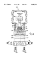
FIG. 3 is an exploded cross-sectional view of a pressure transmitter including a pressure transmitter in accordance with the present invention.
The present invention relates to a pressure sensor of the type used in a pressure transmitter which has an internal sensor surface formed of a brittle material. The sensor surface has been ground, polished or otherwise abraded during manufacture. It has been discovered that such machining of the sensor surface causes the surface to have a friable or crazed surface which can shed particles after the sensor has been assembled. These particles interfere with sensor operation and cause non-linearity in the output of the pressure sensor thereby leading to inaccuracies, and shorten the lifespan of the sensor. Additionally, these particles may puncture diaphragm during overpressure and cause failure of the electrical contact. In the present invention, the sensor surface is heated to cause the brittle material to cohere. Preferably, the heating is not sufficiently high to cause significant deformation in the sensor surface. The sensor surface is allowed to slowly cool and cracks at the surface tend to fill during the heating process. Further, this reduces the friability of the surface and any loose particles become more resistant to separation from the sensor surface, thus reducing the problem with non-linearities.
FIG. 1A is a simplified exploded perspective view of a pressure sensor 10 in accordance with the present invention. Sensor 10 includes first half cell 12 coupled to second half cell 14 with diaphragm 16 suspended therebetween. Half cell 12 includes sensor surface 18 formed therein which carries electrode 20. Half cell 14 includes sensor surface 22 formed therein which carries electrode 24 (not shown in FIG. 1A) . A pressure connection 26 extends through half cell 14 and a similar pressure connection 28 (not shown in FIG. 1A) extends through half cell 12. In accordance with the present invention, sensor surfaces 18 and 22 are heated to cause coherence of any loose particles.
One aspect of the present invention includes the recognition that the process of machining the brittle material causes sensor surfaces 18 and 20 to be crazed surfaces which can shed particles, particularly during the welding process. The particles can interfere with operation of sensor 10 and, in particular, movement of diaphragm 16. This reduces the accuracy and life time of the pressure measurements.
In accordance with the present invention, pressures sensor 10 (and in particular brittle material 46,48) is heated to a sufficiently high temperature for a sufficient duration to cause any loose or partially loose material or particles on surfaces 18,22 to cohere or otherwise bond to the surface such that they will not be dislodged during subsequent operation. For example, if brittle material 46,48 comprises glass, a temperature of between about 500° C. and 550° C. is sufficient to cause this cohesion. In one preferred embodiment, the glass comprises S-8080, melt No. OB2492, part No. 0 3031-0418-0001 having an Index of Refraction of 1.62520-1.62604, a CTE of 115, a Density of 3.51, a Strain Point (°C.) of 373, a Annealing Point (°C.) of 395, a Softening Point (°C.) of 535, a Working Point (°C.) of 785, a Dielectric Constant of 7.9, a Young's Modulus of 58 and Possion's Ratio of 0.024. In one preferred embodiment, the Straining Point is between about 500° and 550° C. Further, the time of such heating should be sufficiently long to allow the cohesion to occur. For example, between about 10 and about 15 minutes. If the heating is sufficiently high for a sufficiently long period, the sensor surface 18,22 will change from an opaque or cloudy appearance to a substantially transparent (translucent) or clear appearance. The resultant sensor surfaces 18,22 are characterized in that they contain cohered (or recohered) particles. The temperature and heating period, however, are preferably not sufficient to allow brittle material 46,48 and surfaces 18,22 to significantly distort due to melting which could lead to inaccuracies in pressure measurements. In one preferred embodiment, the heat treatment is performed in a nitrogen filled atmosphere to prevent oxidation of the components. Additionally, the heat treatment may be applied prior or subsequent to coupling the two cell halves 12,14 together.
In addition to cohering the loose particles, the heat treatment in accordance with the present invention smoothes sensor surfaces 18 and 22 such that electrodes 20 and 24 deposited on surfaces 18,22 are substantially smooth. This reduces the resistivity of the metal in electrodes 20,24 thereby providing improved accuracy. Additionally, the heat treatment may be used to reduce the electrical resistance of the connection between electrical conductors 40 and electrodes 20 and 24. The heat treatment also fills cracks in surfaces 18,22.
FIG. 2 is an exploded cross-sectional view of pressure sensor 10 in housing 30 of pressure transmitter 28 positioned between flanges 32 and 34. Flanges 32 and 34 are coupled to housing 30 by bolts 80 secured by nuts 82 and sealed by O-rings 74 and 76, respectively. Pressure P1 is applied through port 62 in flange 32 to isolation diaphragm 36. Similarly, pressure P2 is applied through port 64 in flange 34 to isolation diaphragm 38.
In operation, pressures P1 and P2 press against respective isolation diaphragms 36 and 38 thereby pressing on a substantially incompressible fill fluid which fills the cavity between center diaphragm and isolation diaphragms 36 and 38. This causes center diaphragm 16 to deflect resulting in a change in capacitance between diaphragm 16 and electrode 20 and diaphragm 16 and electrode 24. Electrical conductors 40 couple transmitter circuitry 42 to electrodes 20 and 24. Transmitter circuitry 42 provides an output related to pressures P1 and P2 as a function of capacitance between electrodes 20,24 and center diaphragm 16 over, for example, a two wire process control loop 44. Such process control loops are known in the process control industry and may comprise, for example, a 4-20 mA current loop.
FIG. 3 is a cross-sectional view of a transmitter 100 including a pressure sensor 102 in accordance with another embodiment of the present invention. Transmitter 100 is known in the industry as having a coplanar design because isolation diaphragms 106 and 108 are aligned generally coplanar. Flange 111 couples to transmitter 100 through bolts 110 to thereby couple pressure P1 and P2 to isolation diaphragms 106 and 108. Gaskets 109 provide a seal between flange 111 and isolation diaphragm 106,108. A substantially incompressible fluid is carried in capillaries 120 which couple to pressure sensor 102. Similar to pressure sensor 10, sensor 102 is formed from two half cells 112,114 filled, respectively, with brittle material 116,118. Electrical conductors 124 couple to capacitor plates (not shown) carried on sensor surfaces of brittle materials 116,118. Diaphragm 122 deflects in response to applied pressures P1 and P2 causing a capacitive change which is detected by transmitter circuitry 122 which provides an output related to pressures P1 and P2 over a two wire process control loop.
A pressure sensor in accordance with the present invention is particularly advantageous for use with pressure transmitters of the type used in the process control industry. Such industrial control pressure transmitters typically must isolate the pressure sensor from the process medium. This requires the use of the isolation fluid which fills the space between the sensor diaphragm and the isolation diaphragm. This isolation causes any loose particles to be sealed within the pressure sensor, such that they may build up over time. Further, the sensor may be subjected to environmental extremes such as temperature fluctuations and vibrations. These extremes exasterbate the problems associated with a friable surface. Simply applying a coating, such as an organic coating, to the sensor surface will not be useful for reduction in the friability of the surface because such a coating may break down when exposed to temperature extremes or the fill oil.
Although the present invention has been described with reference to preferred embodiments, workers skilled in the art will recognize that changes may be made in form and detail without departing from the spirit and scope of the invention. Other types of brittle materials such as ceramics may be used in the present invention. Further, steps in accordance with the method of the present invention may be performed in any order as desired and is not limited to the particular order set forth herein. It will also be apparent to those skilled in the art that a pressure sensor cell in accordance with the present invention may have alternative designs and be used with other types of pressure transmitters.
Claims (10)
1. A method of making a pressure transmitter having a pressure sensor, comprising:
obtaining a cell having a recess formed therein;
filling the recess with a solidified brittle material;
shaping through an abrasion process a friable sensor surface on the brittle material;
assembling a pressure sensor which includes the cell filled with the brittle material;
heating the friable sensor surface during the assembling to cause a reduction in the friability of the surface wherein the heating is performed subsequent to the step of shaping through an abrasion process; and
manufacturing the pressure transmitter which includes the pressure sensor.
2. The method of claim 1 wherein the assembling further includes depositing a sensor plate on the sensor surface.
3. The method of claim 2 wherein the heating is performed prior to the step of depositing.
4. The method of claim 2 wherein the heating is performed subsequent to the step of depositing.
5. The method of claim 1 including providing an electrical conductor which extends through solidified brittle material prior to the assembling.
6. The method of claim 5 wherein the including depositing a capacitor plate onto the sensor surface which electrically contacts the electrical conductor.
7. The method of claim 1 wherein the heating comprises placing the cell in an oven.
8. The method of claim 1 wherein the heating is performed by illuminating the sensor surface with a laser.
9. The method of claim 1 wherein the heating is to a temperature less than a softening temperature of the brittle material.
10. The method of claim 1 wherein the heating does not cause a substantial deformation in shape of the brittle material.
Priority Applications (1)
| Application Number | Priority Date | Filing Date | Title |
|---|---|---|---|
| US09/066,790 US6003219A (en) | 1998-04-24 | 1998-04-24 | Method of making a pressure transmitter having pressure sensor having cohered surfaces |
Applications Claiming Priority (1)
| Application Number | Priority Date | Filing Date | Title |
|---|---|---|---|
| US09/066,790 US6003219A (en) | 1998-04-24 | 1998-04-24 | Method of making a pressure transmitter having pressure sensor having cohered surfaces |
Publications (1)
| Publication Number | Publication Date |
|---|---|
| US6003219A true US6003219A (en) | 1999-12-21 |
Family
ID=22071720
Family Applications (1)
| Application Number | Title | Priority Date | Filing Date |
|---|---|---|---|
| US09/066,790 Expired - Lifetime US6003219A (en) | 1998-04-24 | 1998-04-24 | Method of making a pressure transmitter having pressure sensor having cohered surfaces |
Country Status (1)
| Country | Link |
|---|---|
| US (1) | US6003219A (en) |
Cited By (15)
| Publication number | Priority date | Publication date | Assignee | Title |
|---|---|---|---|---|
| US20060278005A1 (en) * | 2005-05-26 | 2006-12-14 | Broden David A | Pressure sensor using compressible sensor body |
| US20070053758A1 (en) * | 2002-03-18 | 2007-03-08 | Nikken Kosakusho Works Ltd. | Tool holder |
| US20090078054A1 (en) * | 2007-09-20 | 2009-03-26 | Rosemount Inc. | Differential pressure sensor isolation in a process fluid pressure transmitter |
| US7870791B2 (en) | 2008-12-03 | 2011-01-18 | Rosemount Inc. | Method and apparatus for pressure measurement using quartz crystal |
| US20110079086A1 (en) * | 2009-10-01 | 2011-04-07 | Romo Mark G | Pressure transmitter with pressure sensor mount |
| US7954383B2 (en) | 2008-12-03 | 2011-06-07 | Rosemount Inc. | Method and apparatus for pressure measurement using fill tube |
| US8132464B2 (en) | 2010-07-12 | 2012-03-13 | Rosemount Inc. | Differential pressure transmitter with complimentary dual absolute pressure sensors |
| US8234927B2 (en) | 2010-06-08 | 2012-08-07 | Rosemount Inc. | Differential pressure sensor with line pressure measurement |
| US8327713B2 (en) | 2008-12-03 | 2012-12-11 | Rosemount Inc. | Method and apparatus for pressure measurement using magnetic property |
| US8384915B2 (en) | 2010-10-01 | 2013-02-26 | Rosemount Inc. | Test block for use in a welding process |
| US8429978B2 (en) | 2010-03-30 | 2013-04-30 | Rosemount Inc. | Resonant frequency based pressure sensor |
| US8752433B2 (en) | 2012-06-19 | 2014-06-17 | Rosemount Inc. | Differential pressure transmitter with pressure sensor |
| US20140251019A1 (en) * | 2011-10-31 | 2014-09-11 | Rosemount Inc. | Coplanar process fluid pressure sensor module |
| US20140265306A1 (en) * | 2013-03-14 | 2014-09-18 | Rosemount, Inc. | Separately replaceable seal systems for use with a pressure transmitter |
| US11371899B2 (en) | 2018-05-17 | 2022-06-28 | Rosemount Inc. | Measuring element with an extended permeation resistant layer |
Citations (2)
| Publication number | Priority date | Publication date | Assignee | Title |
|---|---|---|---|---|
| US3618390A (en) * | 1969-10-27 | 1971-11-09 | Rosemount Eng Co Ltd | Differential pressure transducer |
| US5624760A (en) * | 1991-10-11 | 1997-04-29 | Caradon Doors & Windows Limited - Cet | Fire resistant glass |
-
1998
- 1998-04-24 US US09/066,790 patent/US6003219A/en not_active Expired - Lifetime
Patent Citations (2)
| Publication number | Priority date | Publication date | Assignee | Title |
|---|---|---|---|---|
| US3618390A (en) * | 1969-10-27 | 1971-11-09 | Rosemount Eng Co Ltd | Differential pressure transducer |
| US5624760A (en) * | 1991-10-11 | 1997-04-29 | Caradon Doors & Windows Limited - Cet | Fire resistant glass |
Cited By (22)
| Publication number | Priority date | Publication date | Assignee | Title |
|---|---|---|---|---|
| US20070053758A1 (en) * | 2002-03-18 | 2007-03-08 | Nikken Kosakusho Works Ltd. | Tool holder |
| US7320568B2 (en) | 2002-03-18 | 2008-01-22 | Nikken Kosakusho Works Ltd. | Tool holder |
| US7401522B2 (en) | 2005-05-26 | 2008-07-22 | Rosemount Inc. | Pressure sensor using compressible sensor body |
| US20060278005A1 (en) * | 2005-05-26 | 2006-12-14 | Broden David A | Pressure sensor using compressible sensor body |
| US20090078054A1 (en) * | 2007-09-20 | 2009-03-26 | Rosemount Inc. | Differential pressure sensor isolation in a process fluid pressure transmitter |
| US7624642B2 (en) | 2007-09-20 | 2009-12-01 | Rosemount Inc. | Differential pressure sensor isolation in a process fluid pressure transmitter |
| US7870791B2 (en) | 2008-12-03 | 2011-01-18 | Rosemount Inc. | Method and apparatus for pressure measurement using quartz crystal |
| US7954383B2 (en) | 2008-12-03 | 2011-06-07 | Rosemount Inc. | Method and apparatus for pressure measurement using fill tube |
| US8327713B2 (en) | 2008-12-03 | 2012-12-11 | Rosemount Inc. | Method and apparatus for pressure measurement using magnetic property |
| US8371175B2 (en) | 2009-10-01 | 2013-02-12 | Rosemount Inc. | Pressure transmitter with pressure sensor mount |
| US20110079086A1 (en) * | 2009-10-01 | 2011-04-07 | Romo Mark G | Pressure transmitter with pressure sensor mount |
| US8429978B2 (en) | 2010-03-30 | 2013-04-30 | Rosemount Inc. | Resonant frequency based pressure sensor |
| US8234927B2 (en) | 2010-06-08 | 2012-08-07 | Rosemount Inc. | Differential pressure sensor with line pressure measurement |
| US8132464B2 (en) | 2010-07-12 | 2012-03-13 | Rosemount Inc. | Differential pressure transmitter with complimentary dual absolute pressure sensors |
| US8384915B2 (en) | 2010-10-01 | 2013-02-26 | Rosemount Inc. | Test block for use in a welding process |
| JP2013542077A (en) * | 2010-10-01 | 2013-11-21 | ローズマウント インコーポレイテッド | Method for certifying a welding process on a test block and production workpiece for use in the welding process |
| US20140251019A1 (en) * | 2011-10-31 | 2014-09-11 | Rosemount Inc. | Coplanar process fluid pressure sensor module |
| US9752945B2 (en) * | 2011-10-31 | 2017-09-05 | Rosemount Inc. | Coplanar process fluid pressure sensor module |
| US8752433B2 (en) | 2012-06-19 | 2014-06-17 | Rosemount Inc. | Differential pressure transmitter with pressure sensor |
| US20140265306A1 (en) * | 2013-03-14 | 2014-09-18 | Rosemount, Inc. | Separately replaceable seal systems for use with a pressure transmitter |
| US9568136B2 (en) * | 2013-03-14 | 2017-02-14 | Rosemount, Inc. | Separately replaceable seal systems for use with a pressure transmitter |
| US11371899B2 (en) | 2018-05-17 | 2022-06-28 | Rosemount Inc. | Measuring element with an extended permeation resistant layer |
Similar Documents
| Publication | Publication Date | Title |
|---|---|---|
| US6003219A (en) | Method of making a pressure transmitter having pressure sensor having cohered surfaces | |
| EP0041886B1 (en) | Capacitive pressure transducer | |
| US4389895A (en) | Capacitance pressure sensor | |
| CA1187714A (en) | High accuracy differential pressure capacitive transducer and methods for making same | |
| US4168518A (en) | Capacitor transducer | |
| CA1296917C (en) | Differential pressure sensor | |
| US7316163B2 (en) | Method of forming a seal between a housing and a diaphragm of a capacitance sensor | |
| AU653164B2 (en) | Capacitive strain gauge | |
| US4763098A (en) | Flip-chip pressure transducer | |
| JP2840390B2 (en) | Pressure transducer | |
| US7284439B2 (en) | Method for producing a pressure sensor for detecting small pressure differences and low pressures | |
| CA1223453A (en) | Pressure sensor with a substantially flat overpressure stop for the measuring diaphragm | |
| CA1077294A (en) | Pressure transmitter with simplified pressure sensing head | |
| US9541461B2 (en) | Ceramic pressure sensor and method for production thereof | |
| JP2009535622A (en) | Pressure sensor using sintered ceramic with a shape close to the net | |
| CA2144832A1 (en) | Capacitive pressure sensors or capacitive differential pressure sensors | |
| EP0198018A1 (en) | Capacitive sensing cell made of brittle material | |
| US5302879A (en) | Temperature/reference package, and method using the same for high pressure, high temperature oil or gas well | |
| US3800413A (en) | Differential pressure transducer | |
| US4710744A (en) | Pressure transducer package | |
| CA2058916C (en) | Piezoresistive pressure transducer with a conductive elastomeric seal | |
| US4501051A (en) | High accuracy differential pressure capacitive transducer and methods for making same | |
| EP0855584B1 (en) | Method for making a pressure transducer | |
| EP1060374B1 (en) | A pressure sensor for detecting small pressure differences and low pressures | |
| JPH0436425Y2 (en) |
Legal Events
| Date | Code | Title | Description |
|---|---|---|---|
| AS | Assignment |
Owner name: ROSEMOUNT INC., MINNESOTA Free format text: ASSIGNMENT OF ASSIGNORS INTEREST;ASSIGNORS:FRICK, ROGER L.;BROWN, GREGORY C.;REEL/FRAME:009139/0958 Effective date: 19980424 |
|
| STCF | Information on status: patent grant |
Free format text: PATENTED CASE |
|
| FPAY | Fee payment |
Year of fee payment: 4 |
|
| FPAY | Fee payment |
Year of fee payment: 8 |
|
| FPAY | Fee payment |
Year of fee payment: 12 |