US5984634A - Fan assembly for a processing unit case - Google Patents
Fan assembly for a processing unit case Download PDFInfo
- Publication number
- US5984634A US5984634A US08/984,343 US98434397A US5984634A US 5984634 A US5984634 A US 5984634A US 98434397 A US98434397 A US 98434397A US 5984634 A US5984634 A US 5984634A
- Authority
- US
- United States
- Prior art keywords
- case
- motherboards
- motherboard
- differently configured
- processing unit
- Prior art date
- Legal status (The legal status is an assumption and is not a legal conclusion. Google has not performed a legal analysis and makes no representation as to the accuracy of the status listed.)
- Expired - Lifetime
Links
Images

Classifications
-
- G—PHYSICS
- G06—COMPUTING; CALCULATING OR COUNTING
- G06F—ELECTRIC DIGITAL DATA PROCESSING
- G06F1/00—Details not covered by groups G06F3/00 - G06F13/00 and G06F21/00
- G06F1/16—Constructional details or arrangements
- G06F1/18—Packaging or power distribution
- G06F1/183—Internal mounting support structures, e.g. for printed circuit boards, internal connecting means
- G06F1/184—Mounting of motherboards
-
- G—PHYSICS
- G06—COMPUTING; CALCULATING OR COUNTING
- G06F—ELECTRIC DIGITAL DATA PROCESSING
- G06F1/00—Details not covered by groups G06F3/00 - G06F13/00 and G06F21/00
- G06F1/16—Constructional details or arrangements
-
- G—PHYSICS
- G06—COMPUTING; CALCULATING OR COUNTING
- G06F—ELECTRIC DIGITAL DATA PROCESSING
- G06F1/00—Details not covered by groups G06F3/00 - G06F13/00 and G06F21/00
- G06F1/16—Constructional details or arrangements
- G06F1/18—Packaging or power distribution
-
- G—PHYSICS
- G06—COMPUTING; CALCULATING OR COUNTING
- G06F—ELECTRIC DIGITAL DATA PROCESSING
- G06F1/00—Details not covered by groups G06F3/00 - G06F13/00 and G06F21/00
- G06F1/16—Constructional details or arrangements
- G06F1/20—Cooling means
-
- H—ELECTRICITY
- H05—ELECTRIC TECHNIQUES NOT OTHERWISE PROVIDED FOR
- H05K—PRINTED CIRCUITS; CASINGS OR CONSTRUCTIONAL DETAILS OF ELECTRIC APPARATUS; MANUFACTURE OF ASSEMBLAGES OF ELECTRICAL COMPONENTS
- H05K7/00—Constructional details common to different types of electric apparatus
- H05K7/20—Modifications to facilitate cooling, ventilating, or heating
- H05K7/20709—Modifications to facilitate cooling, ventilating, or heating for server racks or cabinets; for data centers, e.g. 19-inch computer racks
- H05K7/20836—Thermal management, e.g. server temperature control
Definitions
- This invention relates generally to electrical storage cabinets and more particularly to electrical storage cabinets adapted to house a plurality of processing unit modules.
- the invention also relates to fan assemblies and covers for such cases.
- Data servers are used to move data between a storage system, such as between a Symmetrix Integrated Cached Disk Array storage system and a network.
- the data server typically includes a set AC powered processing unit modules each of which includes a central processing unit (CPU), input/output (I/O) adapter cards, and a main memory programmed to run a variety of software application programs for subscribers to the network.
- These applications include file access, video access and/or network backup.
- a cabinet is provided with a plurality of compartments.
- Each one of the compartments is adapted to have disposed therein a corresponding one of a plurality of processing unit modules.
- Each one of the modules includes a case.
- the case has a motherboard mounting surface adapted to have mounted thereto one of a plurality of differently configured motherboards.
- Each one of the differently configured motherboards has a different arrangement of a CPU, main memory and I/O adapted cards. With such an arrangement, the case is a universal case which may be used for anyone of a repertoire of differently configured motherboards.
- the case also has a bulkhead mounting surface adapted to have mounted thereto one of a plurality of differently configured I/O adapter card bulkheads.
- Each one of the differently configured bulkheads is configured for a corresponding one of the differently configured motherboards.
- the case may be used for one of a repertoire of different I/O adapter card bulkheads which is suitable for one of the motherboards mounted in the case.
- the case has a fan mounting surface adapted to have mounted thereto one of a plurality of differently configured fan assemblies.
- Each one of the differently configured fan assemblies is configured for a corresponding differently configured motherboard.
- the case may be used for one of a repertoire of differently configured fan assemblies which is suitable to provide optimum air-flow cooling to one of the motherboards mounted in the case.
- a case having a motherboard mounting surface adapted to have mounted thereto a CPU, main memory and I/O adapter cards.
- the I/O adapter cards have a front bottom edge adapted for plugging into the motherboard.
- a cover is adapted for mounting to the case over the motherboard. The cover has an anti-vibration member adapted to engage an upper rear edge of the I/O adapter cards and maintain the I/O adapter cards securely plugged into the motherboard.
- the adapter cards are more securely plugged into the motherboard case.
- the case the I/O adapter cards have a front mounting bracket secured to a front portion of the case and the anti-vibration member engages the upper rear edge of the I/O adapter card when the cover is mounted to the case.
- the motherboard has a plurality of I/O adapter cards with front bottom edges thereof plugged into the motherboard, and the anti-vibration member is adapted to engage rear upper edges of the plurality of I/O adapter cards and maintain the I/O adapter cards securely plugged into the motherboard.
- a fan assembly is adapted for mounting to a case.
- the fan assembly includes a mounting plate having an aperture formed therethrough and adapted for affixing to the case with the aperture in registration with an aperture formed through a panel of the case.
- a fan is mounted to the mounting plate with the fan being disposed in registration with the aperture formed in the mounting plate.
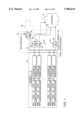
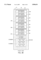
- FIG. 1 is a diagram of a data server according to the invention coupled between a memory system and a network;
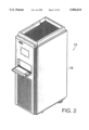
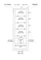
- FIG. 2 is a drawing of the data server of FIG. 1;
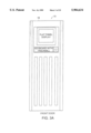
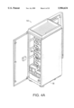
- FIGS. 3A-3C are simplified, diagrammatical sketches of the data server of FIG. 1, FIG. 3A showing the front door of a cabinet used to store the components of the data server of FIG. 2, FIG. 3B showing the front of the cabinet when the front door of FIG. 3A is open; and FIG. 3C is a rear view of the cabinet when a rear door thereof is open.
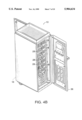
- FIGS. 4A and 4B are perspective views of the data server of FIG. 2; FIG. 4A being a rear perspective view of the data server with the rear door open; and FIG. 4B being a front perspective view of the data server with the front door open;
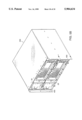
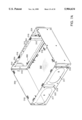
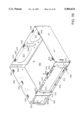
- FIG. 5 is a perspective view of a chassis used by the server of FIG. 2, four such chassis being shown in FIG. 3B, each one of such chassis being adapted to store up to two processing unit modules;
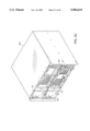
- FIGS. 5A, 5B, and 5C are perspective drawings showing the chassis of FIG. 5 storing two processing modules; FIG. 5A showing an arrangement where both modules are of the same first type; FIG. 5B showing an arrangement where both modules are of the same second type; and FIG. 5C showing an arrangement where one of the two modules is the first type and the other one of the modules is the second type;
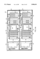
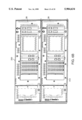
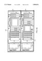
- FIGS. 6A, 6B, and 6C are front elevation drawings showing the chassis of FIG. 5 storing two processing modules; FIG. 6A showing an arrangement where both modules are of the same first type; FIG. 6B showing an arrangement where both modules are of the same second type; and FIG. 6C showing an arrangement where one of the two modules is the first type and the other one of the modules is the second type;
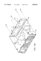
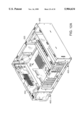
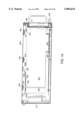
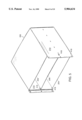
- FIGS. 7A and 7B are rear and front perspective drawings, respectively, of a universal case according to the invention for either the first type or second type of processing unit modules shown in FIGS. 5A-5B, such case being shown with a cover therefor removed;
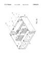
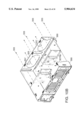
- FIGS. 8A and 8B are exploded perspective drawing of the case of FIGS. 7A and 7B, such drawings showing first and second motherboards for the first and second types of modules, respectively;
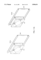
- FIGS. 9A and 9B are exploded perspective drawing of the case of FIGS. 7A and 7B, such drawings showing first and second I/O adapter card bulkheads for the first and second motherboards, respectively;
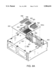
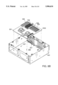
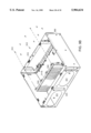
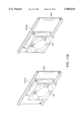
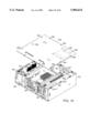
- FIGS. 10A and 10B are exploded, partially broken away perspective drawing of the case of FIGS. 7A and 7B, such drawings showing first and second fan assemblies for the first and second motherboards, respectively;
- FIG. 11A is a perspective view of the fan assemblies for the first motherboard
- FIG. 11B is a perspective view of the fan assemblies for the second motherboard
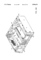
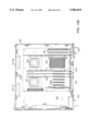
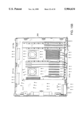
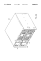
- FIGS. 12A and 12B are front perspective drawings of the cases of FIGS. 7A and 7B configured as the first type and second type of processing unit modules, respectively, such cases being shown with the cover therefor removed;
- FIGS. 13A and 13B are rear perspective drawings of the cases of FIGS. 7A and 7B configured as the first type and second type of processing unit modules, respectively, such cases being shown with the cover therefor removed;
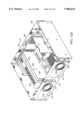
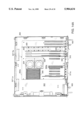
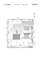
- FIGS. 14A and 14B are top plan drawings of the cases of FIGS. 7A and 7B configured as the first type and second type of processing unit modules, respectively, such cases being shown with the cover therefor removed;
- FIGS. 15A and 15B are top plan drawings of the cases of FIGS. 7A and 7B configured as the first type and second type of processing unit modules, respectively, such cases being shown with the cover therefor removed, such drawing illustrating air-flow through the cases;
- FIG. 16 is an exploded perspective drawing of the case of FIGS. 7A and 7B, such drawing showing a top perspective view of a cover used for the case of FIGS. 7A and 7B;
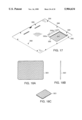
- FIG. 17 is a bottom perspective drawing of the cover of FIG. 16, such cover being shown to have an vibration damping pad according to the invention affixed thereto;
- FIGS. 18A, 18B and 18C are top, side and perspective drawings, respectively, of the vibration damping pad shown in FIG. 17;
- FIG. 19 is a cross-section side elevation view showing the engagement of vibration damping pad FIGS. 18A, 18B and 18C with I/O adapted cards plugged into a motherboard and having a front end affixed to the I/O adapter card bulkhead.
- a data server 10 is shown coupled between a storage system 12 and a network 14.
- the storage system 12 is here a Symmetrix 3500 Integrated Cache Disk Array system manufactured and sold by EMC Corporation, Hopkington, Mass., assignee of the present patent application.
- the storage system 12 is coupled to the data server 10 through a Fast Wide Differential (FWD) SCSI interconnect 16, as shown.
- FWD Fast Wide Differential
- the data server 10 includes, in a single-cabinet 18 shown in FIGS. 2, 3A-3E, 4A, 4B a plurality of, here up to eight hot replaceable processing unit modules 28. Up to seven of the processing unit modules 28 are data movers. The processing unit modules 28 are all interconnected through a local bus, here an Ethernet bus 24 (FIG. 1), as described in detail in co-pending patent application Ser. No. 08/884,740 filed Jun. 30, 1997 entitled “Data Server Having Hot Replaceable Processing Unit Modules", inventors Gallagher et al., the entire subject matter thereof being incorporated herein by reference. (Hot replaceable means that a component can be removed and/or replaced without an interruption to the system's, here server's, operation.)
- FIGS. 5A and 6A show an arrangement where both modules 28 are of the same first type
- FIGS. 5B and 6B show an arrangement where both modules 28 are of the same second type
- FIGS. 5C and 6C show an arrangement where one of the two modules 28 is the first type and the other one of the modules 28 is the second type.
- FIGS. 7A and 7B a universal sheet metal case 300 is shown adapted for either the first or second type of processing unit modules 28.
- FIGS. 12A and 13A show the case 300 configured as the first type of processing unit modules 28, such case 300 being shown with the cover therefor removed; and
- FIGS. 12B and 13B show the case 300 configured as the second type of processing unit modules 28, such case 300 also being shown with the cover therefor removed.
- the front of each case 300 has a pair of lock-release mechanisms 400; one on each front side of the case.
- Each lock-release mechanism 400 is similar to the lock-release mechanism described in the above-referenced patent application and is used to lock the case 300 in the chassis 200 and to remove the case 300 from the chassis 200.
- the case 300 (FIGS.
- FIG. 7A and 7B has a pair of oval shaped holes 317 formed through the rear surface 325 of the case 300 for air flow, to be described.
- the rear surface 325 also serves as a fan mounting surface for fan assemblies to be described.
- a pair of elongated, vertically orientated slots 319 is provided in the rear surface 325 for Teradyne HDM connectors, not shown, as described in the above referenced patent application.
- the processing unit module 28 is configured to enable use of market available processing unit module motherboards.
- the case 300 has a motherboard mounting surface 302 (FIGS. 7A and 7B), here the bottom surface, adapted to have mounted thereto one of a plurality of differently configured motherboards 302a, 302b as shown in FIGS. 8A and 8B respectively.
- Each one of the motherboards 302a, 302b has holes 305 for enabling the motherboards 302a, 302b to snap onto posts 307 projecting upward from the bottom surface 302 of the case 300.
- Each one of the differently configured motherboards 302a, 302b has a different arrangement of a CPU 304, main memory slots 306 and I/O adapted card slots 308.
- case 300 is a universal case which may be used for anyone of a repertoire of differently configured motherboards.
- the case 300 (FIGS. 7A and 7B) also has a front, bulkhead mounting surface 310, here the front bezel, adapted to have mounted thereto one of a plurality of differently configured I/O adapter card bulkheads 311a, 311b by the same mounting mechanism, here by a set of ten screws 312, as indicated in FIGS. 9A and 9B.
- Each one of the differently configured bulkheads 311a, 311b is specifically configured for a corresponding one of the differently configured motherboards 302a, 302b, respectively, as indicated; more particularly for the particular I/O slot 308 (FIGS. 8A and 8B) arrangement used by the motherboard.
- the case 300 may be used for the one of a repertoire of differently I/O adapter card bulkheads 311a, 311b which is suitable for the one of the motherboards 302a, 302b, respectively, as indicated, mounted in the case 300.
- the case 300 has a fan mounting surface 325, here the rear surface, adapted to have mounted thereto one of a plurality of differently configured fan assemblies 327La, 327Ra and 327Lb, 327Rb as indicated in FIGS. 10A and 10B, respectively.
- the fan assembly 327La shown on the left in FIG. 10A is shown more clearly in the left side of FIG. 11A
- the fan assembly 327Ra shown on the right in FIG. 10A is shown more clearly in the right side of FIG. 11A
- the fan assembly 327Lb shown on the left in FIG. 10B is shown more clearly in the left side of FIG. 11B
- each of the fan assemblies 327La, 327Ra, 327Lb, and 327Rb shown in FIGS. 11A and 11B, respectively, has the same shape fan 321 mounting plate 329 each of which is adapted for fastening to the rear surface 325 of case 300 by screws 333 as indicated in FIGS. 10A and 10B.
- Each one of the differently configured fan assemblies 327La, 327Ra is configured for motherboard 302a and fan assemblies 327Lb, 327Rb are configured for motherboard 302b.
- the case 300 may be used for the one of a repertoire of differently configure fan assemblies 327La, 327Ra, 327Lb, 327Rb which is suitable to provide optimum air-flow cooling to the one of the motherboards 302a, 302b mounted in the case 300, as will be described in connection with FIGS. 15A and 15B.
- each one of the fan assemblies 327La, 327Ra, 327Lb, 327Rb is adapted for mounting to the rear surface (i.e., rear panel) 325 of case 300 and has a mounting plate 329 with a grate-like aperture 331 formed therethrough and adapted for affixing to the case 300 with the aperture 331 in registration with an aperture 331' (FIGS. 10A, 10B) formed through the rear panel 325 of the case 300.
- the fans 321 are mounted, here by screws, not numbered, to the mounting plates 329, as shown in FIGS. 11A and 11B with each fan 321 being disposed in registration with the aperture 329, formed in the mounting plate 329.
- FIGS. 12A, 13A and 14A show the case 300 configured as the first type of processing unit modules 28, and FIGS. 12B, 13B and 14B show the case 300 configured as the second type of processing unit modules 28.
- the air flow for the first type processing unit module is shown by the arrows in FIG. 15A and air flow for the second type processing unit module is shown by the arrows in FIG. 15B.
- each case 300 houses a DC powered, environmentally controlled processing unit module 28.
- the processing unit module 28 includes the motherboard 302a, 302b disposed on the bottom surface 302 of the case 300, a data server interconnect printed circuit board 350 (FIGS. 14A and 14B) mounted along one side of the case 300 which plug into a backplane 352 (FIG.
- the server interconnect printed circuit board 350 has mounted to it a DC to DC converter, a DC margin and thermal control unit module, a pair of control busses, a pair of Ethernet 10 Base2 busses, a parallel port interface and various indicators and switches accessible from the front panel of the processing unit module 28.
- the thermal control unit processing unit module 28 is used to control the fans 321 of the fan assemblies 327La, 327Ra and 327Lb, 327Rb, and hence the environment, of such processing unit module 28. Airflow through the data mover processing unit module 28 is from front to back, as shown in FIGS. 15A and 15B.
- the DC operated fans pull air from holes 354 in the front panel (and holes 354 in a honey-combed adapter card filler plate 356 (FIGS. 6A, 13A and 13B) described in the above-referenced patent application) of the processing unit module 28 and through the fans at the rear of the module 28 across the motherboard 302a or 302b depending on the motherboard configuration used in the case 300.
- the motherboards 302a, 302b have CPUs, main memory and a plurality of I/O adapter card slots 308 (FIGS. 8A and 8B).
- I/O adapter cards 420 (FIGS. 13A, 13B, 14A, 14B, 16) have front bottom edges 422 (FIG. 19) adapted for plugging into the I/O slots 308 of the motherboards (FIGS. 16 and 19).
- the cover 348 (FIGS. 16, 17 and 19) is adapted for mounting to the case 300 by screws 358 threading into brackets 316 as indicated in FIGS. 16 and 19.
- the cover 348 has an anti-vibration member 330 (FIGS. 16, 17 and 19).
- the member 330 has a bracket 330a which is riveted onto the cover 348 by rivets 330b.
- the bracket 330a protrudes inwardly in the case 300 when the cover 348 is affixed to the case 300 by mounting screws 358 which thread into the brackets 316, as indicated in FIGS. 16, 17 and 19).
- a resilient pad 323 (FIGS. 18A, 18B and 18C) is affixed to the mounting bracket 319 by a back-mounted adhesive.
- the pad 323 is adapted to engage a rear upper edge 360 of the plurality of I/O adapter cards 420 and maintain the I/O adapter cards 420 securely plugged into the motherboard slots 308 when the cover 348 is mounted (i.e, screwed) onto the case 300 by the screws 358, as indicated in FIG. 19.
- the I/O adapter cards 420 are therefore more securely retained plugged into the motherboard.
- the cover 348 shown in FIGS. 16, 17, and 19 has the anti-vibration member 330 configured (i.e., sized and positioned) to engage the I/O adapter cards plugged into motherboard 302a (FIG.
- each of the I/O adapter cards 420 is a convention adapter card having a front portion 352 mounting bracket 366 (FIGS. 13A and 19) affixed to it.
- the bracket 366 is secured to the front I/O bulkhead 311a (FIG. 11A) by individual screws 368 (FIG. 19) or by an I/O mounting plate described in detail in the above referenced patent application.
- the screws 368 are threaded into holes 500 (FIGS. 9A and 9B) in bulkhead 311a with the mounting bracket 366 wedged between the head of screw 368 and the bulkhead 311b as shown in FIG. 19.
- the bracket 366 is secured to the front panel 311b by the screw 368.
- the pad 323 of the anti-vibration member 330 engages downwardly the rear upper edge 360 of the I/O adapter card 420.
- the pad 323 is a resilient, high density polyurethane soft foam with a 3M Company 950 pressure adhesive backing for affixing it to the metal bracket 319.
Abstract
Description
Claims (2)
Priority Applications (1)
| Application Number | Priority Date | Filing Date | Title |
|---|---|---|---|
| US08/984,343 US5984634A (en) | 1997-12-03 | 1997-12-03 | Fan assembly for a processing unit case |
Applications Claiming Priority (1)
| Application Number | Priority Date | Filing Date | Title |
|---|---|---|---|
| US08/984,343 US5984634A (en) | 1997-12-03 | 1997-12-03 | Fan assembly for a processing unit case |
Publications (1)
| Publication Number | Publication Date |
|---|---|
| US5984634A true US5984634A (en) | 1999-11-16 |
Family
ID=25530473
Family Applications (1)
| Application Number | Title | Priority Date | Filing Date |
|---|---|---|---|
| US08/984,343 Expired - Lifetime US5984634A (en) | 1997-12-03 | 1997-12-03 | Fan assembly for a processing unit case |
Country Status (1)
| Country | Link |
|---|---|
| US (1) | US5984634A (en) |
Cited By (11)
| Publication number | Priority date | Publication date | Assignee | Title |
|---|---|---|---|---|
| US6549979B1 (en) | 2001-06-07 | 2003-04-15 | Emc Corporation | Address mapping in mass storage device mounting system |
| US20030153243A1 (en) * | 2002-02-08 | 2003-08-14 | Gordon Haas | Construction set toy |
| US6628513B1 (en) | 2001-06-07 | 2003-09-30 | Emc Corporation | Mass storage device mounting system |
| US20050280990A1 (en) * | 2004-06-21 | 2005-12-22 | Goodenough Ryan K | Fan module |
| US20060007614A1 (en) * | 2002-01-02 | 2006-01-12 | Ruggedcom Inc. | Environmentally hardened ethernet switch |
| US7293135B1 (en) | 2004-12-30 | 2007-11-06 | Emc Corporation | Invertible disk drive connection scheme |
| US20080037214A1 (en) * | 2006-08-11 | 2008-02-14 | Open Source Systems, Inc. | Computer chassis for two horizontally oriented motherboards |
| US7346674B1 (en) | 2001-06-07 | 2008-03-18 | Emc Corporation | Configurable fibre channel loop system |
| US20090067142A1 (en) * | 2007-09-06 | 2009-03-12 | Hon Hai Precision Industry Co., Ltd. | Retaining mechanism for circuit card |
| US10499525B1 (en) * | 2018-10-22 | 2019-12-03 | Severcube, Inc. | Computing server apparatus |
| CN112764490A (en) * | 2021-01-21 | 2021-05-07 | 长城超云(北京)科技有限公司 | High-throughput low-delay server system suitable for edge end |
Citations (3)
| Publication number | Priority date | Publication date | Assignee | Title |
|---|---|---|---|---|
| US4751872A (en) * | 1987-05-26 | 1988-06-21 | Lawson Jr Theodore J | Ventilation system |
| US5475562A (en) * | 1994-04-22 | 1995-12-12 | At&T Global Information Solutions Company | Structure for cooling an equipment enclosure |
| US5528454A (en) * | 1994-12-29 | 1996-06-18 | Compuserve Incorporated | Cooling device for electronic components arranged in a vertical series and vertical series of electronic devices containing same |
-
1997
- 1997-12-03 US US08/984,343 patent/US5984634A/en not_active Expired - Lifetime
Patent Citations (3)
| Publication number | Priority date | Publication date | Assignee | Title |
|---|---|---|---|---|
| US4751872A (en) * | 1987-05-26 | 1988-06-21 | Lawson Jr Theodore J | Ventilation system |
| US5475562A (en) * | 1994-04-22 | 1995-12-12 | At&T Global Information Solutions Company | Structure for cooling an equipment enclosure |
| US5528454A (en) * | 1994-12-29 | 1996-06-18 | Compuserve Incorporated | Cooling device for electronic components arranged in a vertical series and vertical series of electronic devices containing same |
Cited By (12)
| Publication number | Priority date | Publication date | Assignee | Title |
|---|---|---|---|---|
| US6549979B1 (en) | 2001-06-07 | 2003-04-15 | Emc Corporation | Address mapping in mass storage device mounting system |
| US6628513B1 (en) | 2001-06-07 | 2003-09-30 | Emc Corporation | Mass storage device mounting system |
| US7346674B1 (en) | 2001-06-07 | 2008-03-18 | Emc Corporation | Configurable fibre channel loop system |
| US20060007614A1 (en) * | 2002-01-02 | 2006-01-12 | Ruggedcom Inc. | Environmentally hardened ethernet switch |
| US7276814B2 (en) | 2002-01-02 | 2007-10-02 | Ruggedcom Inc. | Environmentally hardened ethernet switch |
| US20030153243A1 (en) * | 2002-02-08 | 2003-08-14 | Gordon Haas | Construction set toy |
| US20050280990A1 (en) * | 2004-06-21 | 2005-12-22 | Goodenough Ryan K | Fan module |
| US7293135B1 (en) | 2004-12-30 | 2007-11-06 | Emc Corporation | Invertible disk drive connection scheme |
| US20080037214A1 (en) * | 2006-08-11 | 2008-02-14 | Open Source Systems, Inc. | Computer chassis for two horizontally oriented motherboards |
| US20090067142A1 (en) * | 2007-09-06 | 2009-03-12 | Hon Hai Precision Industry Co., Ltd. | Retaining mechanism for circuit card |
| US10499525B1 (en) * | 2018-10-22 | 2019-12-03 | Severcube, Inc. | Computing server apparatus |
| CN112764490A (en) * | 2021-01-21 | 2021-05-07 | 长城超云(北京)科技有限公司 | High-throughput low-delay server system suitable for edge end |
Similar Documents
| Publication | Publication Date | Title |
|---|---|---|
| US6088224A (en) | Cabinet for storing a plurality of processing unit modules | |
| EP0896697B1 (en) | Personal computer enclosure with peripheral device mounting system | |
| US6061237A (en) | Computer with an improved cooling system and a method for cooling a computer | |
| US7097047B2 (en) | Cable management flip tray assembly | |
| US7876557B2 (en) | Disk array device | |
| US6930882B2 (en) | Processor shroud adaptor for multiple CPU locations | |
| US6052281A (en) | Computer chassis with airflow control mechanisms | |
| US6437980B1 (en) | Low profile high density rack mountable enclosure with superior cooling and highly accessible re-configurable components | |
| US7940521B2 (en) | Blade server assembly | |
| US6594150B2 (en) | Computer system having front and rear cable access | |
| US6606253B2 (en) | Scalable internet engine | |
| US5191544A (en) | Personal computer enclosure with shielding | |
| US6580604B1 (en) | Peripheral device bay with adapter plates | |
| US5984634A (en) | Fan assembly for a processing unit case | |
| KR100859760B1 (en) | Scalable internet engine | |
| US6967837B2 (en) | Computer apparatus assembled wirelessly | |
| US20110299239A1 (en) | Computer Case with Upwardly Oriented Add-On Cards and Vertical Airflow | |
| KR960006077B1 (en) | Computer system and personal computer system | |
| US6856514B2 (en) | Toolless thumb screw with adjustable height knob | |
| US20030090867A1 (en) | Modular logic board chassis for a desktop computer | |
| CN101644944A (en) | Computer | |
| US6938181B1 (en) | Field replaceable storage array | |
| US6208520B1 (en) | Method for allowing redundant and non-redundant power supplies in the same computer system | |
| US6833994B2 (en) | Electronics assembly | |
| US20230259181A1 (en) | Fault-tolerant cooling for add-in card |
Legal Events
| Date | Code | Title | Description |
|---|---|---|---|
| AS | Assignment |
Owner name: EMC CORPORATION, MASSACHUSETTS Free format text: ASSIGNMENT OF ASSIGNORS INTEREST;ASSIGNORS:TEACHOUT, JEFFREY;MARKOVICH, NIKOLAI;GALLAGHER, BRIAN;REEL/FRAME:008898/0839 Effective date: 19971126 |
|
| STCF | Information on status: patent grant |
Free format text: PATENTED CASE |
|
| FEPP | Fee payment procedure |
Free format text: PAYOR NUMBER ASSIGNED (ORIGINAL EVENT CODE: ASPN); ENTITY STATUS OF PATENT OWNER: LARGE ENTITY |
|
| FPAY | Fee payment |
Year of fee payment: 4 |
|
| FPAY | Fee payment |
Year of fee payment: 8 |
|
| FEPP | Fee payment procedure |
Free format text: PAYER NUMBER DE-ASSIGNED (ORIGINAL EVENT CODE: RMPN); ENTITY STATUS OF PATENT OWNER: LARGE ENTITY Free format text: PAYOR NUMBER ASSIGNED (ORIGINAL EVENT CODE: ASPN); ENTITY STATUS OF PATENT OWNER: LARGE ENTITY |
|
| FPAY | Fee payment |
Year of fee payment: 12 |
|
| AS | Assignment |
Owner name: CREDIT SUISSE AG, CAYMAN ISLANDS BRANCH, AS COLLATERAL AGENT, NORTH CAROLINA Free format text: SECURITY AGREEMENT;ASSIGNORS:ASAP SOFTWARE EXPRESS, INC.;AVENTAIL LLC;CREDANT TECHNOLOGIES, INC.;AND OTHERS;REEL/FRAME:040134/0001 Effective date: 20160907 Owner name: THE BANK OF NEW YORK MELLON TRUST COMPANY, N.A., AS NOTES COLLATERAL AGENT, TEXAS Free format text: SECURITY AGREEMENT;ASSIGNORS:ASAP SOFTWARE EXPRESS, INC.;AVENTAIL LLC;CREDANT TECHNOLOGIES, INC.;AND OTHERS;REEL/FRAME:040136/0001 Effective date: 20160907 Owner name: CREDIT SUISSE AG, CAYMAN ISLANDS BRANCH, AS COLLAT Free format text: SECURITY AGREEMENT;ASSIGNORS:ASAP SOFTWARE EXPRESS, INC.;AVENTAIL LLC;CREDANT TECHNOLOGIES, INC.;AND OTHERS;REEL/FRAME:040134/0001 Effective date: 20160907 Owner name: THE BANK OF NEW YORK MELLON TRUST COMPANY, N.A., A Free format text: SECURITY AGREEMENT;ASSIGNORS:ASAP SOFTWARE EXPRESS, INC.;AVENTAIL LLC;CREDANT TECHNOLOGIES, INC.;AND OTHERS;REEL/FRAME:040136/0001 Effective date: 20160907 |
|
| AS | Assignment |
Owner name: EMC IP HOLDING COMPANY LLC, MASSACHUSETTS Free format text: ASSIGNMENT OF ASSIGNORS INTEREST;ASSIGNOR:EMC CORPORATION;REEL/FRAME:040203/0001 Effective date: 20160906 |
|
| AS | Assignment |
Owner name: WYSE TECHNOLOGY L.L.C., CALIFORNIA Free format text: RELEASE BY SECURED PARTY;ASSIGNOR:CREDIT SUISSE AG, CAYMAN ISLANDS BRANCH;REEL/FRAME:058216/0001 Effective date: 20211101 Owner name: SCALEIO LLC, MASSACHUSETTS Free format text: RELEASE BY SECURED PARTY;ASSIGNOR:CREDIT SUISSE AG, CAYMAN ISLANDS BRANCH;REEL/FRAME:058216/0001 Effective date: 20211101 Owner name: MOZY, INC., WASHINGTON Free format text: RELEASE BY SECURED PARTY;ASSIGNOR:CREDIT SUISSE AG, CAYMAN ISLANDS BRANCH;REEL/FRAME:058216/0001 Effective date: 20211101 Owner name: MAGINATICS LLC, CALIFORNIA Free format text: RELEASE BY SECURED PARTY;ASSIGNOR:CREDIT SUISSE AG, CAYMAN ISLANDS BRANCH;REEL/FRAME:058216/0001 Effective date: 20211101 Owner name: FORCE10 NETWORKS, INC., CALIFORNIA Free format text: RELEASE BY SECURED PARTY;ASSIGNOR:CREDIT SUISSE AG, CAYMAN ISLANDS BRANCH;REEL/FRAME:058216/0001 Effective date: 20211101 Owner name: EMC IP HOLDING COMPANY LLC, TEXAS Free format text: RELEASE BY SECURED PARTY;ASSIGNOR:CREDIT SUISSE AG, CAYMAN ISLANDS BRANCH;REEL/FRAME:058216/0001 Effective date: 20211101 Owner name: EMC CORPORATION, MASSACHUSETTS Free format text: RELEASE BY SECURED PARTY;ASSIGNOR:CREDIT SUISSE AG, CAYMAN ISLANDS BRANCH;REEL/FRAME:058216/0001 Effective date: 20211101 Owner name: DELL SYSTEMS CORPORATION, TEXAS Free format text: RELEASE BY SECURED PARTY;ASSIGNOR:CREDIT SUISSE AG, CAYMAN ISLANDS BRANCH;REEL/FRAME:058216/0001 Effective date: 20211101 Owner name: DELL SOFTWARE INC., CALIFORNIA Free format text: RELEASE BY SECURED PARTY;ASSIGNOR:CREDIT SUISSE AG, CAYMAN ISLANDS BRANCH;REEL/FRAME:058216/0001 Effective date: 20211101 Owner name: DELL PRODUCTS L.P., TEXAS Free format text: RELEASE BY SECURED PARTY;ASSIGNOR:CREDIT SUISSE AG, CAYMAN ISLANDS BRANCH;REEL/FRAME:058216/0001 Effective date: 20211101 Owner name: DELL MARKETING L.P., TEXAS Free format text: RELEASE BY SECURED PARTY;ASSIGNOR:CREDIT SUISSE AG, CAYMAN ISLANDS BRANCH;REEL/FRAME:058216/0001 Effective date: 20211101 Owner name: DELL INTERNATIONAL, L.L.C., TEXAS Free format text: RELEASE BY SECURED PARTY;ASSIGNOR:CREDIT SUISSE AG, CAYMAN ISLANDS BRANCH;REEL/FRAME:058216/0001 Effective date: 20211101 Owner name: DELL USA L.P., TEXAS Free format text: RELEASE BY SECURED PARTY;ASSIGNOR:CREDIT SUISSE AG, CAYMAN ISLANDS BRANCH;REEL/FRAME:058216/0001 Effective date: 20211101 Owner name: CREDANT TECHNOLOGIES, INC., TEXAS Free format text: RELEASE BY SECURED PARTY;ASSIGNOR:CREDIT SUISSE AG, CAYMAN ISLANDS BRANCH;REEL/FRAME:058216/0001 Effective date: 20211101 Owner name: AVENTAIL LLC, CALIFORNIA Free format text: RELEASE BY SECURED PARTY;ASSIGNOR:CREDIT SUISSE AG, CAYMAN ISLANDS BRANCH;REEL/FRAME:058216/0001 Effective date: 20211101 Owner name: ASAP SOFTWARE EXPRESS, INC., ILLINOIS Free format text: RELEASE BY SECURED PARTY;ASSIGNOR:CREDIT SUISSE AG, CAYMAN ISLANDS BRANCH;REEL/FRAME:058216/0001 Effective date: 20211101 |
|
| AS | Assignment |
Owner name: SCALEIO LLC, MASSACHUSETTS Free format text: RELEASE OF SECURITY INTEREST IN PATENTS PREVIOUSLY RECORDED AT REEL/FRAME (040136/0001);ASSIGNOR:THE BANK OF NEW YORK MELLON TRUST COMPANY, N.A., AS NOTES COLLATERAL AGENT;REEL/FRAME:061324/0001 Effective date: 20220329 Owner name: EMC IP HOLDING COMPANY LLC (ON BEHALF OF ITSELF AND AS SUCCESSOR-IN-INTEREST TO MOZY, INC.), TEXAS Free format text: RELEASE OF SECURITY INTEREST IN PATENTS PREVIOUSLY RECORDED AT REEL/FRAME (040136/0001);ASSIGNOR:THE BANK OF NEW YORK MELLON TRUST COMPANY, N.A., AS NOTES COLLATERAL AGENT;REEL/FRAME:061324/0001 Effective date: 20220329 Owner name: EMC CORPORATION (ON BEHALF OF ITSELF AND AS SUCCESSOR-IN-INTEREST TO MAGINATICS LLC), MASSACHUSETTS Free format text: RELEASE OF SECURITY INTEREST IN PATENTS PREVIOUSLY RECORDED AT REEL/FRAME (040136/0001);ASSIGNOR:THE BANK OF NEW YORK MELLON TRUST COMPANY, N.A., AS NOTES COLLATERAL AGENT;REEL/FRAME:061324/0001 Effective date: 20220329 Owner name: DELL MARKETING CORPORATION (SUCCESSOR-IN-INTEREST TO FORCE10 NETWORKS, INC. AND WYSE TECHNOLOGY L.L.C.), TEXAS Free format text: RELEASE OF SECURITY INTEREST IN PATENTS PREVIOUSLY RECORDED AT REEL/FRAME (040136/0001);ASSIGNOR:THE BANK OF NEW YORK MELLON TRUST COMPANY, N.A., AS NOTES COLLATERAL AGENT;REEL/FRAME:061324/0001 Effective date: 20220329 Owner name: DELL PRODUCTS L.P., TEXAS Free format text: RELEASE OF SECURITY INTEREST IN PATENTS PREVIOUSLY RECORDED AT REEL/FRAME (040136/0001);ASSIGNOR:THE BANK OF NEW YORK MELLON TRUST COMPANY, N.A., AS NOTES COLLATERAL AGENT;REEL/FRAME:061324/0001 Effective date: 20220329 Owner name: DELL INTERNATIONAL L.L.C., TEXAS Free format text: RELEASE OF SECURITY INTEREST IN PATENTS PREVIOUSLY RECORDED AT REEL/FRAME (040136/0001);ASSIGNOR:THE BANK OF NEW YORK MELLON TRUST COMPANY, N.A., AS NOTES COLLATERAL AGENT;REEL/FRAME:061324/0001 Effective date: 20220329 Owner name: DELL USA L.P., TEXAS Free format text: RELEASE OF SECURITY INTEREST IN PATENTS PREVIOUSLY RECORDED AT REEL/FRAME (040136/0001);ASSIGNOR:THE BANK OF NEW YORK MELLON TRUST COMPANY, N.A., AS NOTES COLLATERAL AGENT;REEL/FRAME:061324/0001 Effective date: 20220329 Owner name: DELL MARKETING L.P. (ON BEHALF OF ITSELF AND AS SUCCESSOR-IN-INTEREST TO CREDANT TECHNOLOGIES, INC.), TEXAS Free format text: RELEASE OF SECURITY INTEREST IN PATENTS PREVIOUSLY RECORDED AT REEL/FRAME (040136/0001);ASSIGNOR:THE BANK OF NEW YORK MELLON TRUST COMPANY, N.A., AS NOTES COLLATERAL AGENT;REEL/FRAME:061324/0001 Effective date: 20220329 Owner name: DELL MARKETING CORPORATION (SUCCESSOR-IN-INTEREST TO ASAP SOFTWARE EXPRESS, INC.), TEXAS Free format text: RELEASE OF SECURITY INTEREST IN PATENTS PREVIOUSLY RECORDED AT REEL/FRAME (040136/0001);ASSIGNOR:THE BANK OF NEW YORK MELLON TRUST COMPANY, N.A., AS NOTES COLLATERAL AGENT;REEL/FRAME:061324/0001 Effective date: 20220329 |
|
| AS | Assignment |
Owner name: SCALEIO LLC, MASSACHUSETTS Free format text: RELEASE OF SECURITY INTEREST IN PATENTS PREVIOUSLY RECORDED AT REEL/FRAME (045455/0001);ASSIGNOR:THE BANK OF NEW YORK MELLON TRUST COMPANY, N.A., AS NOTES COLLATERAL AGENT;REEL/FRAME:061753/0001 Effective date: 20220329 Owner name: EMC IP HOLDING COMPANY LLC (ON BEHALF OF ITSELF AND AS SUCCESSOR-IN-INTEREST TO MOZY, INC.), TEXAS Free format text: RELEASE OF SECURITY INTEREST IN PATENTS PREVIOUSLY RECORDED AT REEL/FRAME (045455/0001);ASSIGNOR:THE BANK OF NEW YORK MELLON TRUST COMPANY, N.A., AS NOTES COLLATERAL AGENT;REEL/FRAME:061753/0001 Effective date: 20220329 Owner name: EMC CORPORATION (ON BEHALF OF ITSELF AND AS SUCCESSOR-IN-INTEREST TO MAGINATICS LLC), MASSACHUSETTS Free format text: RELEASE OF SECURITY INTEREST IN PATENTS PREVIOUSLY RECORDED AT REEL/FRAME (045455/0001);ASSIGNOR:THE BANK OF NEW YORK MELLON TRUST COMPANY, N.A., AS NOTES COLLATERAL AGENT;REEL/FRAME:061753/0001 Effective date: 20220329 Owner name: DELL MARKETING CORPORATION (SUCCESSOR-IN-INTEREST TO FORCE10 NETWORKS, INC. AND WYSE TECHNOLOGY L.L.C.), TEXAS Free format text: RELEASE OF SECURITY INTEREST IN PATENTS PREVIOUSLY RECORDED AT REEL/FRAME (045455/0001);ASSIGNOR:THE BANK OF NEW YORK MELLON TRUST COMPANY, N.A., AS NOTES COLLATERAL AGENT;REEL/FRAME:061753/0001 Effective date: 20220329 Owner name: DELL PRODUCTS L.P., TEXAS Free format text: RELEASE OF SECURITY INTEREST IN PATENTS PREVIOUSLY RECORDED AT REEL/FRAME (045455/0001);ASSIGNOR:THE BANK OF NEW YORK MELLON TRUST COMPANY, N.A., AS NOTES COLLATERAL AGENT;REEL/FRAME:061753/0001 Effective date: 20220329 Owner name: DELL INTERNATIONAL L.L.C., TEXAS Free format text: RELEASE OF SECURITY INTEREST IN PATENTS PREVIOUSLY RECORDED AT REEL/FRAME (045455/0001);ASSIGNOR:THE BANK OF NEW YORK MELLON TRUST COMPANY, N.A., AS NOTES COLLATERAL AGENT;REEL/FRAME:061753/0001 Effective date: 20220329 Owner name: DELL USA L.P., TEXAS Free format text: RELEASE OF SECURITY INTEREST IN PATENTS PREVIOUSLY RECORDED AT REEL/FRAME (045455/0001);ASSIGNOR:THE BANK OF NEW YORK MELLON TRUST COMPANY, N.A., AS NOTES COLLATERAL AGENT;REEL/FRAME:061753/0001 Effective date: 20220329 Owner name: DELL MARKETING L.P. (ON BEHALF OF ITSELF AND AS SUCCESSOR-IN-INTEREST TO CREDANT TECHNOLOGIES, INC.), TEXAS Free format text: RELEASE OF SECURITY INTEREST IN PATENTS PREVIOUSLY RECORDED AT REEL/FRAME (045455/0001);ASSIGNOR:THE BANK OF NEW YORK MELLON TRUST COMPANY, N.A., AS NOTES COLLATERAL AGENT;REEL/FRAME:061753/0001 Effective date: 20220329 Owner name: DELL MARKETING CORPORATION (SUCCESSOR-IN-INTEREST TO ASAP SOFTWARE EXPRESS, INC.), TEXAS Free format text: RELEASE OF SECURITY INTEREST IN PATENTS PREVIOUSLY RECORDED AT REEL/FRAME (045455/0001);ASSIGNOR:THE BANK OF NEW YORK MELLON TRUST COMPANY, N.A., AS NOTES COLLATERAL AGENT;REEL/FRAME:061753/0001 Effective date: 20220329 |