US5949334A - Magnetostrictive element having optimized bias-field-dependent resonant frequency characteristic - Google Patents
Magnetostrictive element having optimized bias-field-dependent resonant frequency characteristic Download PDFInfo
- Publication number
- US5949334A US5949334A US08/800,771 US80077197A US5949334A US 5949334 A US5949334 A US 5949334A US 80077197 A US80077197 A US 80077197A US 5949334 A US5949334 A US 5949334A
- Authority
- US
- United States
- Prior art keywords
- bias
- resonant frequency
- strip
- active element
- magnetomechanical
- Prior art date
- Legal status (The legal status is an assumption and is not a legal conclusion. Google has not performed a legal analysis and makes no representation as to the accuracy of the status listed.)
- Expired - Lifetime
Links
Images


Classifications
-
- G—PHYSICS
- G08—SIGNALLING
- G08B—SIGNALLING OR CALLING SYSTEMS; ORDER TELEGRAPHS; ALARM SYSTEMS
- G08B13/00—Burglar, theft or intruder alarms
- G08B13/22—Electrical actuation
- G08B13/24—Electrical actuation by interference with electromagnetic field distribution
- G08B13/2402—Electronic Article Surveillance [EAS], i.e. systems using tags for detecting removal of a tagged item from a secure area, e.g. tags for detecting shoplifting
- G08B13/2405—Electronic Article Surveillance [EAS], i.e. systems using tags for detecting removal of a tagged item from a secure area, e.g. tags for detecting shoplifting characterised by the tag technology used
- G08B13/2408—Electronic Article Surveillance [EAS], i.e. systems using tags for detecting removal of a tagged item from a secure area, e.g. tags for detecting shoplifting characterised by the tag technology used using ferromagnetic tags
-
- G—PHYSICS
- G08—SIGNALLING
- G08B—SIGNALLING OR CALLING SYSTEMS; ORDER TELEGRAPHS; ALARM SYSTEMS
- G08B13/00—Burglar, theft or intruder alarms
- G08B13/22—Electrical actuation
- G08B13/24—Electrical actuation by interference with electromagnetic field distribution
- G08B13/2402—Electronic Article Surveillance [EAS], i.e. systems using tags for detecting removal of a tagged item from a secure area, e.g. tags for detecting shoplifting
- G08B13/2428—Tag details
- G08B13/2437—Tag layered structure, processes for making layered tags
- G08B13/244—Tag manufacturing, e.g. continuous manufacturing processes
-
- G—PHYSICS
- G08—SIGNALLING
- G08B—SIGNALLING OR CALLING SYSTEMS; ORDER TELEGRAPHS; ALARM SYSTEMS
- G08B13/00—Burglar, theft or intruder alarms
- G08B13/22—Electrical actuation
- G08B13/24—Electrical actuation by interference with electromagnetic field distribution
- G08B13/2402—Electronic Article Surveillance [EAS], i.e. systems using tags for detecting removal of a tagged item from a secure area, e.g. tags for detecting shoplifting
- G08B13/2428—Tag details
- G08B13/2437—Tag layered structure, processes for making layered tags
- G08B13/2442—Tag materials and material properties thereof, e.g. magnetic material details
-
- Y—GENERAL TAGGING OF NEW TECHNOLOGICAL DEVELOPMENTS; GENERAL TAGGING OF CROSS-SECTIONAL TECHNOLOGIES SPANNING OVER SEVERAL SECTIONS OF THE IPC; TECHNICAL SUBJECTS COVERED BY FORMER USPC CROSS-REFERENCE ART COLLECTIONS [XRACs] AND DIGESTS
- Y10—TECHNICAL SUBJECTS COVERED BY FORMER USPC
- Y10S—TECHNICAL SUBJECTS COVERED BY FORMER USPC CROSS-REFERENCE ART COLLECTIONS [XRACs] AND DIGESTS
- Y10S148/00—Metal treatment
- Y10S148/003—Anneal
Definitions
- This invention relates to active elements to be used in markers for magnetomechanical electronic article surveillance (EAS) systems, and to methods for making such active elements.
- EAS magnetomechanical electronic article surveillance
- U.S. Pat. No. 4,510,489 issued to Anderson et al., discloses a magnetomechanical EAS system in which markers incorporating a magnetostrictive active element are secured to articles to be protected from theft.
- the active elements are formed of a soft magnetic material, and the markers also include a control element (also referred to as a "bias element") which is magnetized to a pre-determined degree so as to provide a bias field which causes the active element to be mechanically resonant at a pre-determined frequency.
- the markers are detected by means of an interrogation signal generating device which generates an alternating magnetic field at the pre-determined resonant frequency, and the signal resulting from the magnetomechanical resonance is detected by receiving equipment.
- the interrogation signal is turned on and off, or "pulsed", and a "ring-down" signal generated by the active element after conclusion of each interrogation signal pulse is detected.
- magnetomechanical markers are deactivated by degaussing the control element, so that the bias field is removed from the active element thereby causing a substantial shift in the resonant frequency of the active element.
- This technique takes advantage of the fact that the resonant frequency of the active element varies according to the level of the bias field applied to the active element.
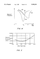
- Curve 20 in FIG. 1A illustrates a bias-field-dependent resonant frequency characteristic typical of certain conventional active elements used in magnetomechanical markers.
- the bias field level H B shown in FIG. 1A is indicative of a level of bias field typically provided by the control element when the magnetomechanical marker is in its active state.
- the bias field level H B is sometimes referred to as the operating point.
- Conventional magnetomechanical EAS markers operate with a bias field of about 6 Oe to 7 Oe.
- the resonant frequency of the active element is substantially shifted (increased) as indicated by arrow 22.
- a typical frequency shift upon deactivation is on the order of 1.5 kHz to 2 kHz.
- U.S. Pat. No. 5,469,140 which has common inventors and a common assignee with the present application, discloses a procedure in which a strip of amorphous metal alloy is annealed in the presence of a saturating transverse magnetic field.
- the resulting annealed strip is suitable for use as the active element in a magnetomechanical marker and has improved ring-down characteristics which enhance performance in pulsed magnetomechanical EAS systems.
- the active elements produced in accordance with the '140 patent also have a hysteresis loop characteristic which tends to eliminate or reduce false alarms that might result from exposure to harmonic-type EAS systems.
- the disclosure of the '140 patent is incorporated herein by reference.
- the techniques disclosed in the '125 patent reduce the sensitivity of the resulting magnetomechanical markers to variations in bias field without unduly diminishing the overall frequency shift which is desired to take place upon degaussing the control element.
- teachings of the '125 patent represent an advance relative to manufacture of transverse-annealed active elements, it would be desirable to provide magnetomechanical EAS markers exhibiting still greater stability in resonant frequency.
- a magnetostrictive element for use as an active element in a magnetomechanical electronic article surveillance marker, the magnetostrictive element being a strip of amorphous metal alloy that has been annealed so as to relieve stress in the magnetostrictive element, the magnetostrictive element having a resonant frequency that varies according to a level of a bias magnetic field applied to the magnetostrictive element and having a bias-field-dependent resonant frequency characteristic such that the resonant frequency of the magnetostrictive element varies by no more than 800 Hz as the bias field applied to the magnetostrictive element varies in the range of 4 Oe to 8 Oe.
- the resonant frequency of the magnetostrictive element varies by no more than 200 Hz over the bias field range of 4 to 8 Oe, and the resonant frequency shift of the magnetostrictive element when the bias field is reduced to 2 Oe from a level in that range is at least 1.5 kHz.
- a magnetomechanical electronic article surveillance marker including an active element in the form of a strip of amorphous magnetostrictive metal alloy, and an element for applying a bias magnetic field at a level H B to the active element, H B being greater than 3 Oe, and the active element having been annealed to relieve stress therein and having a resonant frequency that varies according to a level of the bias magnetic field applied to the element, the active element having a bias-field-dependent resonant frequency characteristic such that the resonant frequency of the active element varies by no more than 600 Hz as the bias field applied to the active element varies in the range of (H B minus 1.5 Oe) to (H B plus 1.5 Oe).
- the resonant frequency of the active element varies by no more than 200 Hz as the bias field varies above or below the operating point H B by as much as 1.5 Oe. Further in accordance with this aspect of the invention, the resonant frequency of the active element is shifted by at least 1.5 kHz when the bias field applied to the active element is reduced from H B to 2 Oe.
- a magnetostrictive element for use as an active element in a magnetomechanical electronic article surveillance marker, the magnetostrictive element being a strip of amorphous metal alloy and having been annealed so as to relieve stress in the magnetostrictive element, the magnetostrictive element having a resonant frequency that varies according to a level of a bias magnetic field applied to the element and having a bias-field-dependent resonant frequency characteristic that has a slope of substantially zero at a point in the range of bias field levels defined as 3 Oe to 9 Oe.
- a magnetomechanical electronic article surveillance marker including an active element in the form of a strip of amorphous magnetostrictive metal alloy, and an element for applying a bias magnetic field at a level H B to the active element, H B being greater than 3 Oe, and the active element having been annealed to relieve stress therein and having a resonant frequency that varies according to a level of the bias magnetic field applied to the active element, the active element having a bias-field-dependent resonant frequency characteristic that has a slope of substantially zero at a point in the range of bias field levels defined as (H B minus 1.5 Oe) to (H B plus 1.5 Oe).
- a magnetostrictive element for use as an active element in a magnetomechanical electronic article surveillance marker, the element being a strip of amorphous metal alloy which has been annealed so as to relieve stress in the magnetostrictive element, the magnetostrictive element having a resonant frequency that varies according to a level of a bias magnetic field applied to the magnetostrictive element and also having a bias-field-dependent resonant frequency characteristic such that the resonant frequency of the magnetostrictive element is at a minimum level at a point in the range of bias field levels defined as 3 Oe to 9 Oe.
- a magnetomechanical electronic article surveillance marker including an active element in the form of a strip of amorphous magnetostrictive metal alloy, and an element for applying a bias magnetic field at a level H B to the active element, H B being greater than 3 Oe, and the active element having been annealed to relieve stress therein, and having a resonant frequency that varies according to a level of the bias magnetic field applied to the active element, the active element having a bias-field-dependent resonant frequency characteristic such that the resonant frequency of the active element is at a minimum level at a point in the range of bias field levels defined as (H B minus 1.5 Oe) to (H B plus 1.5 Oe).
- a magnetostrictive element for use as an active element in a magnetomechanical electronic article surveillance marker, formed by heat-treating a strip of amorphous metal alloy while applying an electrical current along the strip.
- the alloy may have a composition consisting essentially of Fe a Ni b Co c B d Si e , with 30 ⁇ a ⁇ 80, 0 ⁇ b ⁇ 40, 0 ⁇ c ⁇ 40, 10 ⁇ d+e ⁇ 25.
- a preferred composition is Fe 37 .85 Ni 30 .29 Co 15 .16 B 15 .31 Si 1 .39, which composition is preferably heat-treated for 3 minutes at 340° C. while applying a longitudinal current of 2 amperes.
- a method of forming a magnetostrictive element for use in a magnetomechanical marker including the steps of annealing an amorphous metal alloy strip, and during the annealing step, applying an electrical current along the length of the strip.
- a method of forming a magnetostrictive element for use in a magnetomechanical EAS marker including the steps of annealing an amorphous metal alloy strip during application of a magnetic field directed transverse to the longitudinal axis of the strip, and subsequent to the annealing step, applying an electrical current along the longitudinal axis of the strip.
- a magnetic field or tension is applied along the longitudinal axis of the strip.
- a magnetomechanical EAS marker including an active element in the form of a strip of amorphous magnetostrictive metal alloy having a composition consisting essentially of Fe a Ni b Co c Cr d Nb e B f Si g , and an element for applying a bias magnetic field at a level H B to the active element, H B being greater than 3 Oe, and the active element having been annealed to relieve stress therein and having a magnetomechanical coupling factor k at the bias level H B , such that 0.3 ⁇ k ⁇ 0.4, with 69 ⁇ a+b+c ⁇ 75; 26 ⁇ a ⁇ 45; 0 ⁇ b ⁇ 23; 17 ⁇ c ⁇ 40; 2 ⁇ d+e ⁇ 8; 0 ⁇ d; 0 ⁇ e; 20 ⁇ f+g ⁇ 23; f ⁇ 4g.
- a magnetostrictive element for use as an active element in a magnetomechanical electronic article surveillance marker, the element being a strip of amorphous metal alloy and having been annealed so as to relieve stress in the element, the element having a magnetomechanical coupling factor k in a range of about 0.3 to 0.4 at a bias field level that corresponds to a minimum resonant frequency of the element, the alloy including iron, boron and no more than 40% cobalt.
- the alloy may include from 2 to 8% chromium and/or niobium.
- the alloy in such element preferably also includes nickel.
- FIG. 1A illustrates bias-field-dependent resonant frequency characteristics of magnetomechanical markers provided in accordance with conventional practice and in accordance with the present invention.
- FIGS. 1B and 1C illustrate, respectively, a resonant frequency characteristic, and a magnetomechanical coupling factor (k) characteristic, of a magnetostrictive element provided in accordance with the invention.
- FIG. 2 illustrates a bias-field-dependent resonant frequency characteristic of a magnetostrictive element formed by current-annealing in accordance with the present invention.
- FIG. 3 is a bias-field-dependent output signal amplitude characteristic of the magnetostrictive element referred to in connection with FIG. 2.
- FIG. 4 illustrates resonant frequency characteristics of an active element provided in accordance with the invention as exhibited before and after a current-annealing process step.
- FIG. 5 illustrates output signal amplitude characteristics of the magnetostrictive element referred to in connection with FIG. 4, before and after the current-annealing step.
- FIG. 6 illustrates a preferred range of the magnetomechanical coupling factor k in magnetostriction-magnetization space.
- FIG. 7 adds to the illustration of FIG. 6 graphical representations of characteristics in magnetostriction-magnetization space of various alloy compositions.
- FIG. 8 is a ternary composition diagram indicating a preferred range of iron-nickel-cobalt based alloys incorporating chromium or niobium in accordance with the present invention.
- FIG. 9 illustrates an M-H loop characteristic of an active element provided in accordance with the invention.
- FIG. 10 illustrates variations in induced anisotropy according to changes in the temperature employed during cross-field annealing.
- FIG. 11 illustrates resonant frequency characteristics of another example of an active element provided in accordance with the invention as exhibited before and after a current-annealing process step.
- FIG. 12 illustrates output signal amplitude characteristics of the magnetostrictive element referred to in connection with FIG. 11, before and after the current-annealing step.
- the resonant frequency characteristic curve 20 of the prior art transverse-field-annealed active element has a minimum at a bias field value of about H'.
- the value of H' substantially corresponds to the anisotropy field (H a ), which is the longitudinal field required to overcome the transverse anisotropy formed by transverse-field annealing.
- H a the anisotropy field
- a typical level for H' (the level corresponding to the minimum resonant frequency) for the conventional transverse-field-annealed active elements is around (11-15 Oe).
- the most important difficulty is related to the magnetomechanical coupling factor k of the active element if biased at the level H'.
- the coupling factor k has a peak (FIG. 1C), at substantially the same bias level at which the resonant frequency has its minimum (FIG. 1B; the horizontal scales indicative of the bias field level are the same in FIGS. 1B and 1C).
- the solid line portion of the curves shown in FIGS. 1B and 1C corresponds to theoretical models, as well as measured values, for the well of the resonant frequency and the peak of the coupling factor k.
- the dotted line portion of the curves shows a rounded minimum of the frequency curve and a rounded peak of the coupling factor as actually measured and contrary to the theoretical model.
- the peak coupling factor k is about 0.45, which is significantly above the optimum coupling factor 0.3.
- the so-called "quality factor" or Q of the active element would be substantially lower than at the conventional operating point H B so that the active element, when resonating, would dissipate energy much more rapidly, and therefore would have a lower ring-down signal which could not be detected with conventional pulsed-field detection equipment.
- bias element that would be required to provide the higher level bias field H' would be larger and more expensive than conventional bias elements, and more prone to magnetically clamp the active element, which would prevent the marker from operating.
- the difficulties that would be caused by the larger bias element could be prevented by changing the annealing process applied to form the conventional transverse-field-annealed active element so that the anisotropy field H a substantially corresponds to the conventional operating point H B .
- the resulting resonant frequency characteristic is represented by curve 24 in FIG. 1A. Although this characteristic exhibits a minimum and zero slope at or near the conventional operating point, the frequency "well” has very steep sides so that a minor departure of the bias field from the nominal operating point could lead to significant variations in resonant frequency. Furthermore, the peak level of the coupling factor k which corresponds to the frequency minimum of the characteristic curve 24 is substantially above the optimum level 0.3, resulting in fast ring-down and an unacceptably low ring-down signal amplitude.
- a novel active element is formed that has a resonant frequency characteristic such as that represented by dotted line curve 26 of FIG. 1A, with a minimum at or near the conventional operating point H B and a coupling factor k at or near the optimum 0.3 at the operating point.
- the active element provided according to the invention also exhibits a substantial resonant frequency shift when the bias element is degaussed.
- the ribbon has substantially the same geometry as a conventional type of transverse-field-annealed active element, namely a thickness of about 25 microns, a width of about 6 mm, and a length of about 37.6 mm.
- FIG. 2 illustrates the bias-field-dependent resonant frequency characteristic of the resulting active element. It will be observed that the characteristic exhibits a minimum, and substantially zero slope, at around 6 Oe and has very low slope over a range of 4 Oe to 8 Oe. Varying the bias field throughout this range results in no more than about a 200 Hz variation in the resonant frequency. Although reducing the bias field from 6 Oe to less than 2 Oe does not produce a large shift in resonant frequency, such a reduction in bias field does significantly reduce the output signal amplitude.
- FIG. 3 presents a bias-field-dependent output signal characteristic indicating the output signal amplitude provided one millisecond after the end of the interrogation field pulse (sometimes known as the "Al" signal).
- FIG. 3 indicates that the Al signal has a peak of substantially 140 millivolts at around 6 Oe. This is an acceptable signal level for existing magnetomechanical EAS systems.
- the peak of the curve shown in FIG. 3 is rather flat around 6 Oe so that variations in the bias field around the operating point do not greatly reduce the output signal level.
- the bias field is reduced from 6 Oe to about 1 or 2 Oe, there is a very large reduction in the output signal.
- the active element produced in this example is suitable for use in so-called "hard-tag” applications, in which the markers are removed from the article of merchandise upon checkout and for which deactivation by degaussing the control element may not be required. Further, depending on the dynamic range of the detection equipment employed, the reduction in output signal resulting from degaussing the control element may also permit the active element produced in this example to be used in a deactivatable magnetomechanical marker, notwithstanding the relatively small resonant frequency shift caused by removing the bias field.
- alloys having the composition Fe a Ni b Co c B d Si e with 30 ⁇ a ⁇ 80, 0 ⁇ b ⁇ 40, 0 ⁇ c ⁇ 40, 10 ⁇ d+e ⁇ 25, can be treated with current annealing to produce a resonant frequency characteristic like that of curve 26 in FIG. 1A, with a minimum at the conventional bias field operating point, a coupling factor k in the range 0.3 to 0.4 at the operating point, and a substantial reduction in output signal and/or a substantial resonant frequency shift upon removal of the bias field.
- a continuous ribbon of the same material used in Example 1 was continuously annealed at a speed of 24 feet per minute and temperature of 360° C., in the presence of a saturating transverse magnetic field.
- the effective heating path through the heating facility has a length of about 6 feet so that the effective duration of the transverse-field annealing is about 15 seconds.
- a second processing step was performed in which a three ampere current was applied along the length of the ribbon, in the presence of a 5 Oe magnetic field applied along the length of the ribbon, for 10 minutes.
- FIG. 4 shows bias-field-dependent resonant frequency characteristics for the active element produced in accordance with this Example 2 after the transverse-field anneal and prior to the current-treatment step ("cross-mark" curve 28), and after the current-treatment step (triangle-mark curve 30).
- cross-mark curve 28
- trim-mark curve 30 the post-current-treatment characteristic represented by the curve 30 has a minimum, and substantially zero slope, at around 9 Oe, a low slope in the region of the conventional operating point (6 to 7 Oe), and a substantial frequency shift if the bias field is removed.
- FIG. 5 shows the bias-field-dependent Al signal characteristics for the material.
- the cross-mark curve (reference numeral 32) represents the characteristic obtained after the transverse-field-annealing but before the current-treatment step
- the triangle-mark curve (reference 34) represents the characteristic obtained after the current-treatment step. It will be observed that both before and after the current-treatment, a peak amplitude of more than 180 millivolts is achieved near the conventional operating point. Further, the amplitude characteristic provided by the current-treated material is much broader at the peak, so that a high signal level can be obtained even if the operating point is moved to 9 Oe, which is where the resonant frequency is most stable.
- transverse-field-annealed and then current-treated material produced in this Example 2 provides the desired characteristics of resonant frequency stability, high-ring down signal output (optimal k and satisfactory Q) at the resonant frequency well, and substantial frequency shift upon removal of the bias field.
- Example 2 The same material was continuously annealed in the same manner as in Example 2, and then the current-treatment step was performed with a current of 2.8 amperes applied along the length of the ribbon, in the presence of the 5 Oe longitudinal field, for 3 minutes.
- the resulting resonant frequency and amplitude characteristics are shown, respectively, as curve 30' in FIG. 11 and curve 34' in FIG. 12.
- a magnetomechanical coupling factor k of 0.3 corresponds to a maximum ring-down signal level.
- k in the range 0.28 to 0.40 satisfactory signal amplitude is also provided. If k is greater than 0.4, the output signal amplitude is substantially reduced, and if k is much less than 0.3 the initial signal level produced by the interrogation pulse is reduced, again leading to reduced ring-down output level.
- a preferred range for k is about 0.30 to 0.35.
- the coupling coefficient k is related to the magnetization M S at saturation, the magnetostriction coefficient ⁇ S , the anisotropy field H a , Young's modulus at saturation E M , and the applied longitudinal field H according to the following equation: ##EQU1## This relationship is described in "Magnetomechanical Properties of Amorphous Metals.” J. D. Livingston, Phys. Stat. Sol., (a) 70, pp. 591-596 (1982).
- Equation (1) holds only for values of H less than or equal to H a , above which field level, in theory, k drops to zero.
- E M has a value of about 1.2 ⁇ 10 12 erg/cm 3 .
- the desired operating point implies a level of H a of 6 Oe.
- k be in the range 0.28 to 0.4 when H approaches H a . This requires a substantial reduction in k relative to the material that would have the characteristic represented by curve 24.
- E M , H, and H a as constants, it can be seen that k can be reduced by reducing the magnetostriction ⁇ S and/or by increasing the magnetization M S .
- Increasing the magnetization is also beneficial in that the output signal is also increased, but the level of saturation magnetization that is possible in amorphous magnetic material is limited.
- a desirable region in the magnetostriction-magnetization space is indicated by the shaded region referenced at 36 in FIG. 6.
- FIG. 7 is similar to FIG. 6, with magnetostriction-magnetization characteristics of a number of compositions superimposed.
- Curve 38 in FIG. 7 represents a range of compositions from Fe 80 B 20 to Fe 20 Ni 60 B 20 . It will be observed that the FeNiB curve 38 misses the desired region 36 and can be expected to result in undesirably high levels of k in the region corresponding to the desired levels of magnetization.
- the point labeled A corresponds to a composition known as Metglas 2826MB, which is about Fe 40 Ni 38 Mo 4 B 18 , and has an undesirably high coupling factor k.
- the 2826MB alloy is used as-cast (i.e., without annealing) as the active element in some conventional magnetomechanical markers.
- the casting process is subject to somewhat variable results, including variations in transverse anisotropy, so that in some cases the 2826MB material has a level of H a close to the conventional operating point, although H a for 2826MB as-cast is typically substantially above the conventional operating point.
- the curve 40 corresponds to Fe--Co--B alloys and passes through the desired region 36.
- the point referred to at 43 on curve 40 is within the preferred region 36 and corresponds to Fe 20 Co 60 B 20 .
- the latter composition can be expected to have a desirable coupling factor k at the preferred operating point, such a material would be quite expensive to produce because of the high cobalt content.
- point B which is approximately Co 74 Fe 6 B 20 , there is substantially zero magnetostriction.
- curves 38 and 40 The data for curves 38 and 40 is taken from "Magnetostriction of Ferromagnetic Metallic Glasses", R. C. O'Handley, Solid State Communications, vol. 21, pages 1119-1120, 1977.
- the present invention proposes that an amorphous metal alloy in the preferred region 36 be formed with a lower cobalt component by adding a few atomic percent of chromium and/or niobium to the amorphous metal composition.
- a curve 42 is defined by points 1, 2, 3, 4, and corresponds to a range of FeCrB alloys. These four points are, respectively, Fe 80 Cr 3 B 17 ; Fe 78 Cr 5 B 17 ; Fe 77 Cr 6 B 17 ; and Fe 73 Cr 10 B 17 .
- Curve 44 is defined by points 5-7 and corresponds to a range of FeNbB alloys.
- the points 5-7 shown on curve 44 are, respectively, Fe 80 Nb 3 B 17 ; Fe 78 Nb 5 B 17 ; and Fe 73 Nb 10 B 17 .
- Point 6 on the FeNbB curve 44 provides substantially the same magnetostriction-magnetization characteristics as the alloy Fe 32 Co 18 Ni 32 B 13 Si 5 used to produce the transverse-field-annealed active elements according to the teachings of the above-referenced '125 patent.
- FIG. 8 is a ternary diagram for alloys in which the combined proportion of iron, nickel and cobalt is approximately 77%, subject to reduction by a few percent to accommodate addition of a few percent of chromium and/or niobium.
- the obliquely-shaded region 46 in FIG. 8 corresponds to compositions having up to 3 or 4% niobium and/or chromium and having magnetization and magnetostriction characteristics expected to be in the preferred region 36 of FIGS. 6 and 7. It will be noted that the examples i-iii of Table 1 fall within the region 46.
- An adjoining horizontally shaded region 48 corresponds to compositions having 5-8% chromium that are also expected to be in the preferred region 36.
- a composition selected from the preferred range is to be transverse-field-annealed to generate a transverse anisotropy with a desired anisotropy field H a in the range of about 6 Oe to 8 Oe.
- the anisotropy field H a essentially corresponds to the "knee" portion of the M-H loop, as shown in FIG. 9.
- the annealing temperature and time can be selected to provide the desired anisotropy field H a according to the characteristics of the selected material.
- T c Curie temperature
- the selected annealing temperature T a must therefore be below T c for the selected material.
- the composition of the material may be adjusted, according to known techniques, to set the Curie temperature T c at an appropriate point.
- T c is in the range 380°-480° C.
- a preferred value of T c is 450° C. It is preferred that annealing be carried out at a temperature from 10° C. to 100° C. less than T c for a time in the range of 10 seconds to 10 minutes, depending on the annealing temperature selected.
- FIG. 10 illustrates how the resulting anisotropy field H a varies with annealing temperature and annealing time.
- a higher level of H a is achieved as the annealing time is increased, up to a limit indicated by line 50 in FIG. 10.
- the maximum level of H a that can be achieved for a selected annealing temperature generally increases as the difference between the annealing temperature and the Curie temperature T c increases.
- the selected annealing temperature is too low to provide a sufficient amount of atomic relaxation in a reasonable time, then the anisotropy field H a will fail to reach its equilibrium strength indicated by line 50.
- annealing temperatures For a given desired level of H a , there are two different annealing temperatures that may be selected for a given annealing time, as indicated at points 52 and 54, corresponding to annealing temperatures T a1 and Ta 2 , respectively, either of which may be selected to produce the H a level indicated by line 56 for the annealing time indicated by curve 58. Longer annealing times, represented by curves 60 and 62, would produce higher levels of H a if the temperature T a1 were selected, but not if the temperature T a2 were selected.
- a shorter annealing time, indicated by curve 64, would come close to producing the level of H a indicated by line 56 if the annealing temperature were T a2 , but would substantially fail to produce any field-induced anisotropy if temperature T a1 were selected.
- the active elements produced in accordance with the present invention may be incorporated in magnetomechanical markers formed with conventional housing structures and including conventional bias elements.
- the bias elements may be formed of a low coercivity material such as those described in U.S. patent application Ser. No. 08/697,629, filed Aug. 28, 1996 (which has common inventors and a common assignee with the present application) .
- One such low coercivity material is designated as "MagnaDur 20-4", commercially available from Carpenter Technology Corporation, Reading, Pa.
- It is particularly advantageous to use active elements provided according to the present invention with a low-coercivity bias element because such bias elements are more susceptible than conventional bias materials to suffering a small decrease in magnetization upon exposure to relatively low level alternating magnetic fields.
- the low-coercivity bias elements are therefore somewhat likely to vary in a small way in terms of actual bias field provided by the bias element, such minor variations will not significantly shift the resonant frequency of the active elements provided in accordance with the present invention.
Abstract
Description
              TABLE 1
______________________________________
Composition (atom %)
Ex.                                    M.sub.s
                                             λ
No.   Fe    Co    Ni  Cr   Nb  B   Si  (Gauss)
                                             (10.sup.-6)
                                                   k.sub.max
______________________________________
i.    35    34    6   2    0   20  3   1000  12    0.4
ii.   31    30    15  2    0   19  3   900   10    0.36
iii.  31    30    15  0    2   19  3   800   12    0.445
iv.   38    27    7   6    0   19  3   1000  10    0.35
v.    33    21    17  6    0   20  3   800   9     0.35
vi.   40    18    14  6    0   19  3   900   9     0.33
______________________________________
Claims (35)
Priority Applications (10)
| Application Number | Priority Date | Filing Date | Title |
|---|---|---|---|
| US08/800,771 US5949334A (en) | 1995-10-02 | 1997-02-14 | Magnetostrictive element having optimized bias-field-dependent resonant frequency characteristic |
| DE69830477T DE69830477T2 (en) | 1997-02-14 | 1998-02-04 | MAGNETOSTRICTIVE ELEMENT WITH OPTIMIZED POLARIZATION FIELD DEPENDENT RESONANCE FREQUENCY CHARACTERISTICS |
| BRPI9807387-7A BR9807387B1 (en) | 1997-02-14 | 1998-02-04 | magnetomechanical marker for electronic article surveillance, method of formation of a magnetostrictive element and magnetomechanical eas marker. |
| PCT/US1998/000072 WO1998036392A1 (en) | 1997-02-14 | 1998-02-04 | Magnetostrictive element having optimized bias-field-dependent resonant frequency characteristic |
| AU62383/98A AU736092B2 (en) | 1997-02-14 | 1998-02-04 | Magnetostrictive element having optimized bias-field-dependent resonant frequency characteristic |
| JP53571998A JP4091664B2 (en) | 1997-02-14 | 1998-02-04 | Magneto-electronic article monitoring marker, magneto-electronic article monitoring system, and magnetostrictive element forming method |
| CA002280148A CA2280148C (en) | 1997-02-14 | 1998-02-04 | Magnetostrictive element having optimized bias-field-dependent resonant frequency characteristic |
| EP98904524A EP0960408B1 (en) | 1997-02-14 | 1998-02-04 | Magnetostrictive element having optimized bias-field-dependent resonant frequency characteristic |
| ARP980100593A AR011130A1 (en) | 1997-02-14 | 1998-02-11 | ELECTRONIC MAGNETOMECHANICAL SURVEILLANCE MARKER OF ARTICLES, METHOD TO MAKE A MAGNETOSTRICTIVE ELEMENT FOR USE WITH THE MARKER AND ELECTRONIC MAGNETOMECHANICAL SECURITY ARTICLE TO BE USED WITH SUCH MARKER |
| US09/165,566 US6057766A (en) | 1997-02-14 | 1998-10-02 | Iron-rich magnetostrictive element having optimized bias-field-dependent resonant frequency characteristic |
Applications Claiming Priority (2)
| Application Number | Priority Date | Filing Date | Title |
|---|---|---|---|
| US08/538,026 US5684459A (en) | 1995-10-02 | 1995-10-02 | Curvature-reduction annealing of amorphous metal alloy ribbon |
| US08/800,771 US5949334A (en) | 1995-10-02 | 1997-02-14 | Magnetostrictive element having optimized bias-field-dependent resonant frequency characteristic |
Related Parent Applications (1)
| Application Number | Title | Priority Date | Filing Date |
|---|---|---|---|
| US08/538,026 Continuation-In-Part US5684459A (en) | 1995-10-02 | 1995-10-02 | Curvature-reduction annealing of amorphous metal alloy ribbon |
Related Child Applications (1)
| Application Number | Title | Priority Date | Filing Date |
|---|---|---|---|
| US09/165,566 Continuation-In-Part US6057766A (en) | 1997-02-14 | 1998-10-02 | Iron-rich magnetostrictive element having optimized bias-field-dependent resonant frequency characteristic |
Publications (1)
| Publication Number | Publication Date |
|---|---|
| US5949334A true US5949334A (en) | 1999-09-07 |
Family
ID=25179310
Family Applications (1)
| Application Number | Title | Priority Date | Filing Date |
|---|---|---|---|
| US08/800,771 Expired - Lifetime US5949334A (en) | 1995-10-02 | 1997-02-14 | Magnetostrictive element having optimized bias-field-dependent resonant frequency characteristic |
Country Status (9)
| Country | Link |
|---|---|
| US (1) | US5949334A (en) |
| EP (1) | EP0960408B1 (en) |
| JP (1) | JP4091664B2 (en) |
| AR (1) | AR011130A1 (en) |
| AU (1) | AU736092B2 (en) |
| BR (1) | BR9807387B1 (en) |
| CA (1) | CA2280148C (en) |
| DE (1) | DE69830477T2 (en) |
| WO (1) | WO1998036392A1 (en) |
Cited By (6)
| Publication number | Priority date | Publication date | Assignee | Title |
|---|---|---|---|---|
| US20070194927A1 (en) * | 2006-02-15 | 2007-08-23 | Johannes Maximilian Peter | Electronic article surveillance marker |
| US20080030339A1 (en) * | 2006-08-07 | 2008-02-07 | Tci, Ltd. | Electronic article surveillance marker |
| US20080136571A1 (en) * | 2006-02-15 | 2008-06-12 | Johannes Maxmillian Peter | Electronic article surveillance marker |
| US20090195386A1 (en) * | 2006-02-15 | 2009-08-06 | Johannes Maxmillian Peter | Electronic article surveillance marker |
| US9275529B1 (en) | 2014-06-09 | 2016-03-01 | Tyco Fire And Security Gmbh | Enhanced signal amplitude in acoustic-magnetomechanical EAS marker |
| US9418524B2 (en) | 2014-06-09 | 2016-08-16 | Tyco Fire & Security Gmbh | Enhanced signal amplitude in acoustic-magnetomechanical EAS marker |
Families Citing this family (2)
| Publication number | Priority date | Publication date | Assignee | Title |
|---|---|---|---|---|
| US6057766A (en) * | 1997-02-14 | 2000-05-02 | Sensormatic Electronics Corporation | Iron-rich magnetostrictive element having optimized bias-field-dependent resonant frequency characteristic |
| WO2008032274A2 (en) * | 2006-09-13 | 2008-03-20 | Megasec Ltd. | Magneto-mechanical markers for use in article surveilance system |
Citations (24)
| Publication number | Priority date | Publication date | Assignee | Title |
|---|---|---|---|---|
| US4236946A (en) * | 1978-03-13 | 1980-12-02 | International Business Machines Corporation | Amorphous magnetic thin films with highly stable easy axis |
| US4475962A (en) * | 1982-07-08 | 1984-10-09 | Sony Corporation | Annealing method for amorphous magnetic alloy |
| US4510489A (en) * | 1982-04-29 | 1985-04-09 | Allied Corporation | Surveillance system having magnetomechanical marker |
| US4510490A (en) * | 1982-04-29 | 1985-04-09 | Allied Corporation | Coded surveillance system having magnetomechanical marker |
| US4622543A (en) * | 1984-03-22 | 1986-11-11 | Anderson Iii Philip M | Surveillance system having acoustic magnetomechanical marker |
| US4637843A (en) * | 1982-05-06 | 1987-01-20 | Tdk Corporation | Core of a noise filter comprised of an amorphous alloy |
| US4686516A (en) * | 1984-11-26 | 1987-08-11 | Sensormatic Electronics Corporation | Method, system and apparatus for use in article surveillance |
| US4797658A (en) * | 1984-11-26 | 1989-01-10 | Sensormatic Electronics Corporation | Article surveillance marker capable of being deactivated by relieving the retained stress therein and method and system for deactivating the marker |
| WO1990003652A1 (en) * | 1988-09-26 | 1990-04-05 | Allied-Signal Inc. | Metallic glass alloys for mechanically resonant target surveillance systems |
| US5154983A (en) * | 1989-10-18 | 1992-10-13 | Victor Company Of Japan, Ltd. | Magnetic alloy |
| US5225951A (en) * | 1985-12-27 | 1993-07-06 | Sharp Kabushiki Kaisha | Thin film magnetic head with reduced internal stresses |
| US5252144A (en) * | 1991-11-04 | 1993-10-12 | Allied Signal Inc. | Heat treatment process and soft magnetic alloys produced thereby |
| US5310975A (en) * | 1992-12-23 | 1994-05-10 | General Electric Company | Method and apparatus for the continuous field annealing of amorphous metal transformer cores |
| US5456718A (en) * | 1992-11-17 | 1995-10-10 | Szymaitis; Dennis W. | Apparatus for detecting surgical objects within the human body |
| US5469140A (en) * | 1994-06-30 | 1995-11-21 | Sensormatic Electronics Corporation | Transverse magnetic field annealed amorphous magnetomechanical elements for use in electronic article surveillance system and method of making same |
| US5495231A (en) * | 1995-04-13 | 1996-02-27 | Alliedsignal Inc. | Metallic glass alloys for mechanically resonant marker surveillance systems |
| US5494534A (en) * | 1995-03-17 | 1996-02-27 | Industrial Technology Research Institute | Method of heat treating an amorphous soft magnetic article |
| US5514229A (en) * | 1993-11-24 | 1996-05-07 | Ramot-University Authority For Applied Research And Industrial Development Ltd., Tel Aviv University | Method of producing transparent and other electrically conductive materials |
| US5539380A (en) * | 1995-04-13 | 1996-07-23 | Alliedsignal Inc. | Metallic glass alloys for mechanically resonant marker surveillance systems |
| US5565849A (en) * | 1995-02-22 | 1996-10-15 | Sensormatic Electronics Corporation | Self-biased magnetostrictive element for magnetomechanical electronic article surveillance systems |
| US5568125A (en) * | 1994-06-30 | 1996-10-22 | Sensormatic Electronics Corporation | Two-stage annealing process for amorphous ribbon used in an EAS marker |
| US5628840A (en) * | 1995-04-13 | 1997-05-13 | Alliedsignal Inc. | Metallic glass alloys for mechanically resonant marker surveillance systems |
| US5676767A (en) * | 1994-06-30 | 1997-10-14 | Sensormatic Electronics Corporation | Continuous process and reel-to-reel transport apparatus for transverse magnetic field annealing of amorphous material used in an EAS marker |
| US5684459A (en) * | 1995-10-02 | 1997-11-04 | Sensormatic Electronics Corporation | Curvature-reduction annealing of amorphous metal alloy ribbon |
-
1997
- 1997-02-14 US US08/800,771 patent/US5949334A/en not_active Expired - Lifetime
-
1998
- 1998-02-04 DE DE69830477T patent/DE69830477T2/en not_active Expired - Lifetime
- 1998-02-04 BR BRPI9807387-7A patent/BR9807387B1/en not_active IP Right Cessation
- 1998-02-04 WO PCT/US1998/000072 patent/WO1998036392A1/en active IP Right Grant
- 1998-02-04 CA CA002280148A patent/CA2280148C/en not_active Expired - Lifetime
- 1998-02-04 EP EP98904524A patent/EP0960408B1/en not_active Expired - Lifetime
- 1998-02-04 JP JP53571998A patent/JP4091664B2/en not_active Expired - Lifetime
- 1998-02-04 AU AU62383/98A patent/AU736092B2/en not_active Expired
- 1998-02-11 AR ARP980100593A patent/AR011130A1/en unknown
Patent Citations (24)
| Publication number | Priority date | Publication date | Assignee | Title |
|---|---|---|---|---|
| US4236946A (en) * | 1978-03-13 | 1980-12-02 | International Business Machines Corporation | Amorphous magnetic thin films with highly stable easy axis |
| US4510489A (en) * | 1982-04-29 | 1985-04-09 | Allied Corporation | Surveillance system having magnetomechanical marker |
| US4510490A (en) * | 1982-04-29 | 1985-04-09 | Allied Corporation | Coded surveillance system having magnetomechanical marker |
| US4637843A (en) * | 1982-05-06 | 1987-01-20 | Tdk Corporation | Core of a noise filter comprised of an amorphous alloy |
| US4475962A (en) * | 1982-07-08 | 1984-10-09 | Sony Corporation | Annealing method for amorphous magnetic alloy |
| US4622543A (en) * | 1984-03-22 | 1986-11-11 | Anderson Iii Philip M | Surveillance system having acoustic magnetomechanical marker |
| US4686516A (en) * | 1984-11-26 | 1987-08-11 | Sensormatic Electronics Corporation | Method, system and apparatus for use in article surveillance |
| US4797658A (en) * | 1984-11-26 | 1989-01-10 | Sensormatic Electronics Corporation | Article surveillance marker capable of being deactivated by relieving the retained stress therein and method and system for deactivating the marker |
| US5225951A (en) * | 1985-12-27 | 1993-07-06 | Sharp Kabushiki Kaisha | Thin film magnetic head with reduced internal stresses |
| WO1990003652A1 (en) * | 1988-09-26 | 1990-04-05 | Allied-Signal Inc. | Metallic glass alloys for mechanically resonant target surveillance systems |
| US5154983A (en) * | 1989-10-18 | 1992-10-13 | Victor Company Of Japan, Ltd. | Magnetic alloy |
| US5252144A (en) * | 1991-11-04 | 1993-10-12 | Allied Signal Inc. | Heat treatment process and soft magnetic alloys produced thereby |
| US5456718A (en) * | 1992-11-17 | 1995-10-10 | Szymaitis; Dennis W. | Apparatus for detecting surgical objects within the human body |
| US5310975A (en) * | 1992-12-23 | 1994-05-10 | General Electric Company | Method and apparatus for the continuous field annealing of amorphous metal transformer cores |
| US5514229A (en) * | 1993-11-24 | 1996-05-07 | Ramot-University Authority For Applied Research And Industrial Development Ltd., Tel Aviv University | Method of producing transparent and other electrically conductive materials |
| US5469140A (en) * | 1994-06-30 | 1995-11-21 | Sensormatic Electronics Corporation | Transverse magnetic field annealed amorphous magnetomechanical elements for use in electronic article surveillance system and method of making same |
| US5568125A (en) * | 1994-06-30 | 1996-10-22 | Sensormatic Electronics Corporation | Two-stage annealing process for amorphous ribbon used in an EAS marker |
| US5676767A (en) * | 1994-06-30 | 1997-10-14 | Sensormatic Electronics Corporation | Continuous process and reel-to-reel transport apparatus for transverse magnetic field annealing of amorphous material used in an EAS marker |
| US5565849A (en) * | 1995-02-22 | 1996-10-15 | Sensormatic Electronics Corporation | Self-biased magnetostrictive element for magnetomechanical electronic article surveillance systems |
| US5494534A (en) * | 1995-03-17 | 1996-02-27 | Industrial Technology Research Institute | Method of heat treating an amorphous soft magnetic article |
| US5495231A (en) * | 1995-04-13 | 1996-02-27 | Alliedsignal Inc. | Metallic glass alloys for mechanically resonant marker surveillance systems |
| US5539380A (en) * | 1995-04-13 | 1996-07-23 | Alliedsignal Inc. | Metallic glass alloys for mechanically resonant marker surveillance systems |
| US5628840A (en) * | 1995-04-13 | 1997-05-13 | Alliedsignal Inc. | Metallic glass alloys for mechanically resonant marker surveillance systems |
| US5684459A (en) * | 1995-10-02 | 1997-11-04 | Sensormatic Electronics Corporation | Curvature-reduction annealing of amorphous metal alloy ribbon |
Non-Patent Citations (4)
| Title |
|---|
| Livingston, "Magnetomechanical Properties of Amorphous Metals", Phys. Stat. Sol., vol. 70, pp. 591-596, 1982. |
| Livingston, Magnetomechanical Properties of Amorphous Metals , Phys. Stat. Sol. , vol. 70, pp. 591 596, 1982. * |
| O Handley, Magnetostriction of Ferromagnetic Metallic Glasses , Solid State Communications , vol. 21, pp. 1119 1122, 1977. * |
| O'Handley, "Magnetostriction of Ferromagnetic Metallic Glasses", Solid State Communications, vol. 21, pp. 1119-1122, 1977. |
Cited By (10)
| Publication number | Priority date | Publication date | Assignee | Title |
|---|---|---|---|---|
| US20070194927A1 (en) * | 2006-02-15 | 2007-08-23 | Johannes Maximilian Peter | Electronic article surveillance marker |
| US20080084307A1 (en) * | 2006-02-15 | 2008-04-10 | Peter Johannes M | Electronic article surveillance marker |
| US20080136571A1 (en) * | 2006-02-15 | 2008-06-12 | Johannes Maxmillian Peter | Electronic article surveillance marker |
| US20090195386A1 (en) * | 2006-02-15 | 2009-08-06 | Johannes Maxmillian Peter | Electronic article surveillance marker |
| US7779533B2 (en) | 2006-02-15 | 2010-08-24 | Phenix Label Company, Inc. | Electronic article surveillance marker |
| US20080030339A1 (en) * | 2006-08-07 | 2008-02-07 | Tci, Ltd. | Electronic article surveillance marker |
| US9275529B1 (en) | 2014-06-09 | 2016-03-01 | Tyco Fire And Security Gmbh | Enhanced signal amplitude in acoustic-magnetomechanical EAS marker |
| US9418524B2 (en) | 2014-06-09 | 2016-08-16 | Tyco Fire & Security Gmbh | Enhanced signal amplitude in acoustic-magnetomechanical EAS marker |
| US9640852B2 (en) | 2014-06-09 | 2017-05-02 | Tyco Fire & Security Gmbh | Enhanced signal amplitude in acoustic-magnetomechanical EAS marker |
| US9711020B2 (en) | 2014-06-09 | 2017-07-18 | Tyco Fire & Security Gmbh | Enhanced signal amplitude in acoustic-magnetomechanical EAS marker |
Also Published As
| Publication number | Publication date |
|---|---|
| CA2280148C (en) | 2007-05-08 |
| JP4091664B2 (en) | 2008-05-28 |
| AU736092B2 (en) | 2001-07-26 |
| CA2280148A1 (en) | 1998-08-20 |
| BR9807387B1 (en) | 2011-08-23 |
| AR011130A1 (en) | 2000-08-02 |
| WO1998036392A1 (en) | 1998-08-20 |
| EP0960408B1 (en) | 2005-06-08 |
| EP0960408A4 (en) | 2002-05-22 |
| AU6238398A (en) | 1998-09-08 |
| DE69830477D1 (en) | 2005-07-14 |
| EP0960408A1 (en) | 1999-12-01 |
| DE69830477T2 (en) | 2006-03-16 |
| JP2001511928A (en) | 2001-08-14 |
| BR9807387A (en) | 2000-03-14 |
Similar Documents
| Publication | Publication Date | Title |
|---|---|---|
| CA2146814C (en) | Transverse magnetic field annealed amorphous magnetomechanical elements for use in electronic article surveillance system and method of making same | |
| US6057766A (en) | Iron-rich magnetostrictive element having optimized bias-field-dependent resonant frequency characteristic | |
| EP0121649B2 (en) | Amorphous antipilferage marker | |
| US5825290A (en) | Active element for magnetomechanical EAS marker incorporating particles of bias material | |
| EP1066612B1 (en) | Redistributing magnetic charge in bias element for magnetomechanical eas marker | |
| JP3955623B2 (en) | Metallic glass alloys for monitoring devices with mechanically resonating markers | |
| US5949334A (en) | Magnetostrictive element having optimized bias-field-dependent resonant frequency characteristic | |
| CA2492950C (en) | Transverse magnetic field annealed amorphous magnetomechanical elements for use in electronic article surveillance system and method of making same | |
| EP0895208A2 (en) | Transverse magnetic field annealed amorphous magnetomechanical elements for use in electronic article surveillance system and method of making same | |
| AU711803B2 (en) | Transverse magnetic field annealed amorphous magnetomechanical elements for use in electronic article surveillance system and method of making same | |
| AU738871B2 (en) | Transverse magnetic field annealed amorphous magnetomechanical elements for use in electronic article surveillance system and method of making same |
Legal Events
| Date | Code | Title | Description |
|---|---|---|---|
| AS | Assignment |
Owner name: SENSORMATIC ELECTRONICS CORPORATION, FLORIDA Free format text: ASSIGNMENT OF ASSIGNORS INTEREST;ASSIGNORS:LIAN, MING REN;COFFEY, KEVIN;HO, WING;AND OTHERS;REEL/FRAME:008627/0513 Effective date: 19970602 |
|
| STCF | Information on status: patent grant |
Free format text: PATENTED CASE |
|
| CC | Certificate of correction | ||
| FEPP | Fee payment procedure |
Free format text: PAYOR NUMBER ASSIGNED (ORIGINAL EVENT CODE: ASPN); ENTITY STATUS OF PATENT OWNER: LARGE ENTITY |
|
| AS | Assignment |
Owner name: SENSORMATIC ELECTRONICS CORPORATION, FLORIDA Free format text: MERGER/CHANGE OF NAME;ASSIGNOR:SENSORMATIC ELECTRONICS CORPORATION;REEL/FRAME:012991/0641 Effective date: 20011113 |
|
| FPAY | Fee payment |
Year of fee payment: 4 |
|
| FPAY | Fee payment |
Year of fee payment: 8 |
|
| AS | Assignment |
Owner name: SENSORMATIC ELECTRONICS, LLC,FLORIDA Free format text: MERGER;ASSIGNOR:SENSORMATIC ELECTRONICS CORPORATION;REEL/FRAME:024213/0049 Effective date: 20090922 Owner name: SENSORMATIC ELECTRONICS, LLC, FLORIDA Free format text: MERGER;ASSIGNOR:SENSORMATIC ELECTRONICS CORPORATION;REEL/FRAME:024213/0049 Effective date: 20090922 |
|
| FPAY | Fee payment |
Year of fee payment: 12 |
|
| AS | Assignment |
Owner name: ADT SERVICES GMBH, SWITZERLAND Free format text: ASSIGNMENT OF ASSIGNORS INTEREST;ASSIGNOR:SENSORMATIC ELECTRONICS, LLC;REEL/FRAME:029894/0856 Effective date: 20130214 |
|
| AS | Assignment |
Owner name: TYCO FIRE & SECURITY GMBH, SWITZERLAND Free format text: MERGER;ASSIGNOR:ADT SERVICES GMBH;REEL/FRAME:030290/0731 Effective date: 20130326 |