US5890068A - Wireless location system - Google Patents
Wireless location system Download PDFInfo
- Publication number
- US5890068A US5890068A US08/725,560 US72556096A US5890068A US 5890068 A US5890068 A US 5890068A US 72556096 A US72556096 A US 72556096A US 5890068 A US5890068 A US 5890068A
- Authority
- US
- United States
- Prior art keywords
- signal
- generating
- function
- toa
- received signal
- Prior art date
- Legal status (The legal status is an assumption and is not a legal conclusion. Google has not performed a legal analysis and makes no representation as to the accuracy of the status listed.)
- Expired - Lifetime
Links
Images


Classifications
-
- H—ELECTRICITY
- H04—ELECTRIC COMMUNICATION TECHNIQUE
- H04W—WIRELESS COMMUNICATION NETWORKS
- H04W64/00—Locating users or terminals or network equipment for network management purposes, e.g. mobility management
-
- G—PHYSICS
- G01—MEASURING; TESTING
- G01S—RADIO DIRECTION-FINDING; RADIO NAVIGATION; DETERMINING DISTANCE OR VELOCITY BY USE OF RADIO WAVES; LOCATING OR PRESENCE-DETECTING BY USE OF THE REFLECTION OR RERADIATION OF RADIO WAVES; ANALOGOUS ARRANGEMENTS USING OTHER WAVES
- G01S5/00—Position-fixing by co-ordinating two or more direction or position line determinations; Position-fixing by co-ordinating two or more distance determinations
- G01S5/02—Position-fixing by co-ordinating two or more direction or position line determinations; Position-fixing by co-ordinating two or more distance determinations using radio waves
- G01S5/06—Position of source determined by co-ordinating a plurality of position lines defined by path-difference measurements
-
- Y—GENERAL TAGGING OF NEW TECHNOLOGICAL DEVELOPMENTS; GENERAL TAGGING OF CROSS-SECTIONAL TECHNOLOGIES SPANNING OVER SEVERAL SECTIONS OF THE IPC; TECHNICAL SUBJECTS COVERED BY FORMER USPC CROSS-REFERENCE ART COLLECTIONS [XRACs] AND DIGESTS
- Y10—TECHNICAL SUBJECTS COVERED BY FORMER USPC
- Y10T—TECHNICAL SUBJECTS COVERED BY FORMER US CLASSIFICATION
- Y10T70/00—Locks
- Y10T70/50—Special application
- Y10T70/5611—For control and machine elements
- Y10T70/5757—Handle, handwheel or knob
Definitions
- This invention relates to positioning, location finding and tracking of Wireless Transceivers (WTs) particularly wireless telephones and radio tags.
- WTs Wireless Transceivers
- Wireless telephones include cellular, cordless, mobile and PCS (Personal Communication Systems) telephones while radio tags include passive and active RF identification tags.
- E911 enhanced 911
- E911 services provide the 911 operator with information such as calling number, address, and the primary subscriber's name. This enables the operator to dispatch emergency response teams without waiting for the caller to provide their position verbally.
- the location of the caller is currently only available via verbal communication.
- the only positional information that may be derived from the current cellular infrastructure is the cell site with which the cellular caller is communicating. For cell sizes in the order of kilometers, this is not sufficient.
- the coordinates could be given in one of many formats:
- the wireless location system faces technological challenges. Two of these challenges are location accuracy, and processing time (to provide a location reading).
- the location accuracy performance for a wireless location technology is lower-bounded by the Cramer-Rao lower bound on the rms location error which depends directly on two factors:
- the radio frequency (RF) channels are spaced by 30 KHz which is a relatively small BW compared to systems designed primarily for location such as GPS with a BW of 1 MHz over C/A (Coarse Acquisition) channels and ISM-based location systems with a typical bandwidth of 10 MHz.
- GPS the location system uses initially a conventional sliding correlator to obtain a set of pseudo-ranges (one pseudo-range per satellite). The pseudo-ranges are then used in trilateration to obtain a position fix of the GPS receiver.
- a typical accuracy for a commercial one point (i.e. no differential reception) GPS receiver with C/A code is around 30 m rms without Selective Availability (SA).
- an AMPs land-based location system which uses initially a conventional sliding correlator at each location acquisition station to obtain a TOA estimate of the transmitted radio signal followed by a hyperbolic (differential) trilateration of all the TOA estimates (at some central site) should offer a location accuracy of around an unacceptable 900 m rms assuming no multipath.
- the cellular frequency band is between 800 and 900 MHz and the propagation characteristics at these UHF frequencies will have a significant impact on positioning by trilateration as shown in Parsons D., "The Mobile Radio Propagation Channel," John Wiley & Sons, New York, 1992. That the ranges measured correspond to Line Of Sight (LOS) distances is a major assumption made when estimating position by trilateration.
- LOS Line Of Sight
- the dominant transmission mode in this band is LOS, reflections from natural and man-made objects as well as diffraction around said objects are also possibilities. Multipath and diffraction allow the cellular signal to propagate in heavily built up areas as well as indoors.
- the measured ranges are longer than the true LOS distance which introduces error into the trilateration process.
- the propagation distance at UHF is relatively short. This allows frequency reuse in the cellular system but limits the number of observables in the trilateration process. For instance, in a dense urban environment with a delay spread of 3 microseconds (as shown in Hata, M., "Empirical Formula for Radio Propagation Loss in Land Mobile Radio Services," IEEE Transactions on Vehicular Technology, Vol. VT-29, No. 3, August 1980) multipath causes the location accuracy to degrade to more than 1400 m rms.
- Correlation is an effective method of estimating TOA when the signal is known.
- the resolution of TOA estimation by correlation is a function of the bit rate and hence the bandwidth.
- correlators are an integral part of the delay lock loop (DLL) mechanism used to track satellite signals as shown in Spilker, J. J., "GPS Signal Structure and Performance Characteristics," Global Positioning System, Volume I, The Institute of Navigation, Washington D.C., 1980.
- DLL delay lock loop
- the first purpose is to enable multiple access to the L1 and L2 carrier frequencies. This allows each satellite to transmit data over a common frequency channel.
- the second purpose is to allow for pseudoranging.
- the time delay between the received satellite code and the code replica within the receiver is a measure of the range between the satellite and receiver. Since the satellite signal is continuous a delay lock loop is able to track the signal. This enables the signal to be despread and the data demodulated.
- GPS receivers require several minutes from a cold start to attain an acceptable reading.
- time for the location information to be available depends on two factors:
- GPS is to use the cellular signals themselves.
- PRN Pseudo Random Noise
- both signals are not continuous and do not consist entirely of Pseudo Random Noise (PRN) codes. Therefore, it is not necessary to employ a DLL to track them for the purpose of despreading.
- PRN Pseudo Random Noise
- convolution to estimate TOA. Convolution of the received signal with a stored replica of the transmitted signal results in a correlation peak at the delay between the two signals. Rather than convolve in the time domain, it is sometimes more convenient to multiply in the frequency domain.
- Both the received signal and its replica are first transformed to the frequency domain where they are multiplied and the result inverse transformed to the time domain.
- the resolution is limited to that of the Fourier transform.
- the traditional resolution bound on Fourier-based methods is the Rayleigh resolution criterion as shown in Haykin, S., "Adaptive Filter Theory," 2nd Edition, Prentice Hall, Englewood Cliffs, N.J., 1991, wherein the Rayleigh resolution is the inverse of the sampling period.
- the resolution of a system based on the TOA of cellular signals does not approach the resolution of GPS based wireless location systems.
- a super-resolution algorithm is defined as one in which the resolution is greater than the Rayleigh resolution.
- an AMPs-based cellular telephone is used as an example for the WT to be located.
- AMPs the North American analog standard for cellular telephones, is widely used in North America with about 26 million subscribers;
- Such a choice for a WT does not preclude using the invention with any other standard such as IS-54, IS-95, GSM, DECT, PHS, CDPD, etc., or any other WT such as radio tags.
- the AMPs signal that is to be monitored may be either:
- the RECC carries data and can be easily monitored. It is used for registering the mobile subscriber with a specific base station, answering pages and for placing calls. It can be used in a TDOA as well as an Angle-of-Arrival (AOA) location system. It consists of a precursor followed by several repeated words that contain information regarding the mobile subscriber and the calling number. Therefore, a 911 call can be easily monitored on such a channel.
- the precursor consists of a dotting sequence (30 bits), a barker code (11 bit word sync) and a color code (7 bits).
- the transmission time for one registration signal is approximately 80 ms.
- the RVC carries mainly analog voice, except when the mobile terminal is "audited" by the base station over the forward voice channel (FVC).
- FVC forward voice channel
- the mobile terminal is in the Waiting For Order mode and must confirm the order received on the FVC channel by replying with a "blank-and-burst" message.
- the order can be one of the following:
- the "blank-and-burst" message is primarily used for hand-offs and also for order confirmations requested by the Base Station.
- the message stream consists of a dotting sequence (101 bits), a barker code (11 bits) and several repeated words which are interleaved by a smaller dotting sequence (37 bits) and a barker code. Since the data message is controlled by individual network requests, a non-network integrated wireless location system would have difficulty monitoring the RVC, identifying the mobile subscriber, and determining its location.
- this invention presents a TDOA-based wireless location system which has the primary task to solve either for (x,y,z), the three-dimensional location information of a Wireless Transceiver (WT) or for (x,y), the latitude and longitude of a WT.
- WT Wireless Transceiver
- it requires a minimum of three (independent) equations.Each one of the (independent) equations can be formed by an independent Monitoring Station (MS) which produces a TOA estimate of the transmitted radio signal. All the TOA estimates are then collected at a Central Site (CS) to be used for solving for the unknowns through Hyperbolic (differential) Trilateration.
- MS Monitoring Station
- CS Central Site
- Step 1) the time required for monitoring the transmitted radio signal on either the RECC channel or the RVC channel, followed by the time for processing the received signal in order to estimate its TOA relative to a time reference; (an appropriate time reference could be the GPS Time);
- Step 2) the time required for downloading each TOA estimate from its corresponding Monitoring Station (MS) to a central site, followed by the time for processing all TOA estimates through hyperbolic (differential) trilateration in order to estimate the location of the mobile terminal;
- an appropriate central site could be the Mobile Switching Center (MSC) and an appropriate trilateration method could be least squares-based;
- Step 3 the time required for overlaying the mobile subscriber's geographical location with individual Public Safety Answering Point (PSAP) coverage regions for determining appropriate PSAP routing.
- PSAP Public Safety Answering Point
- Positioning uses signals transmitted by the cellular telephone on either the RECC channel or the RVC channel. These signals are first correlated (either in time or in frequency) in order to achieve a coarse resolution of the Time of Arrival (TOA) of the transmitted signal at each cell site. Then, using Super-Resolution techniques such as MUSIC (MUltiple Signal Identification and Classification) a much finer resolution of the TOA can be achieved. TOA will be measured at various MSs whose precise positions are known. GPS receivers located at the cell sites and running in time transfer mode will provide time synchronization. Hyperbolic trilateration is then performed to estimate either the three-dimensional position (x,y,z) of the Cellular Telephone (CT) or its latitude and longitude (x,y).
- CT Three-dimensional position
- x,y the Cellular Telephone
- FIG. 1 is a schematic showing a Wireless Transceiver (WT) in a cell that transmits a radio signal s(t).
- WT Wireless Transceiver
- CT Cellular Telephone
- FIG. 2 is a schematic showing location of a WT in relation to several monitoring stations MS1, MS2, MS3.
- the signal transmitted by the WT is monitored by a number of MSs.
- the WT is an AMPs-based Cellular Telephone
- either its registration on the RECC or its blank-and-burst on the RVC are monitored by the intended BS in addition to a number of other MSs.
- a minimum of four MSs are required to be able to solve for the three unknowns (x,y,z).
- FIG. 3 is a schematic showing temporal relation of signals transmitted by the WT.
- the signal is transmitted by the WT at time ⁇ to ⁇ and received at the ith MS at time ⁇ TOA1 ⁇ .
- Each MS processes the received signal using the receiver in FIG. 7 in order to estimate its TOA with a fine resolution.
- FIG. 4 is a schematic showing the relation of each monitoring station to a central site.
- Each MS down-loads its fine resolution TOA information to a Central Site (CS) which uses it to solve for the coordinates (x,y,z) of the WT using TDOA-based Hyperbolic Trilateration as explained in FIGS. 5 and 6.
- CS Central Site
- FIG. 5 is a schematic showing how a wireless transceiver is located from two TOA. Using two TOAs one can find the two-dimensional locus (trajectory) of points (which correspond to a unique TDOA) where the WT could be located.
- FIG. 6 is a schematic illustrating location of a wireless transceiver using hyperbolic trilateration.
- three TOAs one can estimate the coordinates (x,y) of the WT as the intersection of the two locili (not to scale) each corresponding to a TDOA that is independent from the other TDOA.
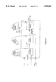
- FIG. 7 is a schematic showing the components of the transmitter in the WT and the receiver in the ith MS.
- FIG. 8 is a schematic showing the components of the RF receiver Front End (703) in FIG. 7 in the MS.
- the MS could be located in the BS site and the receiver multicoupler could be used by the MS.
- FIG. 9 is a schematic showing the components of the Receiver Multicoupler (801) in FIG. 8 in the case when the WT to be located is an AMPs-based Cellular Telephone.
- FIG. 10 is a schematic showing the components of the RF to BaseBand Receiver (802) in FIG. 8.
- FIG. 11 is a schematic showing the components of Processor1 (704) in FIG. 7 in the receiver of the ith MS.
- FIG. 12 is a schematic showing the components of Processor2 (1102) in FIG. 11.
- FIG. 13 is a schematic showing the components of Sliding Correlator (1201) in FIG. 12.
- FIG. 14 is a schematic showing the components of Acquisition Device (1103) in FIG. 11.
- FIG. 15 is a schematic showing the components of the Processor3 (1104) in FIG. 11.
- FIG. 16 is a schematic showing the components of the Processor4 (1506) in FIG. 15.
- FIG. 17 is a schematic showing the components of the Conventional TOA estimator.
- FIG. 1 illustrates the Transmission by a WT (101) of a radio Transmitted Signal s(t) (103).
- the WT is an AMPs-based Cellular Telephone (CT)
- CT Cellular Telephone
- the WT transmits a signal either in the form of a registration over the RECC channel or in the form of a blank-and-burst signal over the RVC channel.
- the transmission is intended for the BS (102) with the most suitable RSSI.
- FIG. 2 illustrates the Reception of the signal transmitted by the WT by a number of Monitoring Stations (MSs) (201).
- MSs Monitoring Stations
- the WT is an AMPs-based CT
- either its registration on the RECC channel or its blank-and-burst on the RVC are monitored by the intended BS and by a number of MSs as well.
- a minimum of four MSs are required to be able to solve for the three unknowns (x,y,z).
- FIG. 3 illustrates the Time of Transmission ⁇ t o ⁇ and the ith Time of Arrival TOA i of the signal transmitted by the WT and received by the ith MS.
- the ith MS processes the received signal using the receiver in FIG. 7 in order to estimate its corresponding TOA i with a fine resolution.
- FIG. 4 illustrates the Second Stage of the Wireless location system where the ith MS down-loads it's fine resolution estimate TOA i of TOA i to a CS (401).
- the CS consists of three blocks:
- the first block is a Difference Unit (402) which generates the estimated Time Difference of Arrival (TDOA i ,1 ) between TOA i and a chosen TOA 1 .
- TDOA i ,1 the estimated Time Difference of Arrival
- the second block is a Position Estimator (403) which uses all the TDOA i ,1 estimates to solve for the coordinates (x,y,z) of the WT using TDOA-based Hyperbolic Trilateration (as shown in Turin, G. L. et al., "A Statistical Model of Urban Multipath Propagation," IEEE Transactions on Vehicular Technology, Vol. VT-21, No. 1, February 1972) as explained in FIGS. 5 and 6. Without loss of generality, FIG.
- FIG. 6 illustrates the two intersecting Trajectories for the two-dimensional coordinates (x,y) of the WT based on TDOA 2 ,1 and TDOA 3 ,1.
- (x,y) it is possible to solve for (x,y) as the intersection between the two trajectories obtained using three TOAs.
- (x,y,z) we require four TOAs.
- FIG. 7 illustrates a typical WT Transmitter (705) and a typical ith MS Receiver (706).
- FIG. 7 is described as four blocks where the first two blocks are contained in the transmitter of the WT and the last two blocks are contained in the receiver of the ith MS. The blocks are described as follows:
- the first block (701) in FIG. 7 is a Source of the signal s(t) (103) transmitted by the WT.
- the second block (702) is the RF Transmitter Front End which takes s(t) and generates an RF signal for transmission.
- the third block (703) is the RF Receiver Front End which receives the RF signal and generates r i (t) which is a distorted delayed replica of s(t).
- the delay is directly related to the propagation time between WT and MS. Such a block is explained further in FIG. 8.
- the fourth block (704) is the Processor 1 which receives r i (t) and generates an estimate TOA i of the TOA of the transmitted signal at the ith MS. Such a block is explained further in FIG. 11.
- FIG. 8 illustrates the RF Receiver Front End (703) in FIG. 7 as two blocks:
- the first block (801) is an optional Receiver Multicoupler (which is a standard BS equipment) in case the WT is an AMPs-base CT and in case the MS is located at the BS site. This is one of the three advantages mentioned above regarding using the cellular infrastructure. Such a block is explained further in FIG. 9.
- the second block is an RF-to-BaseBand (BB) Receiver (which belongs to each MS). Such a block is explained further in FIG. 10.
- BB RF-to-BaseBand
- FIG. 9 illustrates the Receiver Multicoupler (801) in FIG. 8 as three blocks. As mentioned above such a block is optional in case the MS is located at the BS site and in case the MS uses the BS antenna; (in some cases it is not recommended to use the BS antenna such as when the cell is sectorized and the BS antenna covers only one sector).
- the first block (901) is a Preselect Filter (with a large bandwidth such as 25 MHz) to remove any adjacent channel interference.
- the second block (902) is a Low Noise Amplifier (LNA 1 ) to amplify the filtered signal before allowing too much noise to contaminate it due to the attenuation in the splitter (903) that follows.
- LNA 1 Low Noise Amplifier
- the third block (903) is a 1:6 Splitter which splits the signal into 6 equal parts thereby attenuating the power of the signal by a factor of 6.
- FIG. 10 illustrates the RF-to-BB Receiver (802) in FIG. 8 as two IF stages.
- the RF-to-BB receiver is designed with only one IF stage or even with no IF (also known as zero IF receiver or direct conversion receiver).
- the RF-to-BB receiver with two IF stages consists of a number of blocks as shown in FIG. 10:
- the first block (1001) is a Filter which filters the undesired signals from the desired one.
- the second block, LNA 2 , (1002) is a Low Noise Amplifier which performs a first stage amplification.
- the first block, IF stage 1 , (1003) is a down-converter stage using a mixer and a Local Oscillator (LO 1 ) set at a first Intermediate Frequency (IF 1 ).
- the second block, LNA 3 , (1004) is a Low Noise Amplifier which performs a second stage amplification.
- the third block, IF stage 2 , (1005) is a down-converter stage using a mixer and a Local Oscillator (LO) set at a second Intermediate Frequency (IF 2 ).
- LO Local Oscillator
- the fourth block, LNA 4 , (1006) is a Low Noise Amplifier which performs a third stage amplification.
- the fifth block (1007) is a demodulator which converts the second IF signal into a BB signal for further processing by Processor 1 (704).
- FIG. 11 illustrates Processor 1 (704) in FIG. 7 which receives r i (t) and generates TOA i .
- Processor 1 consists of four blocks:
- the first block (1101) is a Source of the Generic Received Signal r(t) (1105). It can be either a signal generator or a look-up table.
- the Generic Received Signal r(t) (1105) corresponds to r i (t) under ideal conditions, i.e. when the Transmitted Signal s(t) (103) is transmitted over the RF Transmitter Front End (702), an ideal channel whose impulse response is a Dirac-delta function d(t) located at the origin (i.e. without dispersion, propagation delay, distortion or noise) and received using the RF Receiver Front End (703).
- the second block (1102) is Processor 2 which receives r(t) (1105) and generates its Power Spectral Density (PSD) ⁇ X r (f) ⁇ . Processor 2 is further explained in FIG. 12.
- the third block (1103) is Acquisition Device which receives two inputs and generates a Time Stamp.
- the two inputs are: the Generic Received Signal r(t) (1105) and the received signal r i (t) at the ith MS.
- the Acquisition Device (1103) is further explained in FIG. 13.
- the fourth block (1104) is Processor 3 which receives four inputs and generates TOA i .
- the four inputs are: the PSD X r (f) of r(t) (1105) output from Processor 2 (1102), the Generic Received Signal r(t) (1105) output from Source (1101), the time stamp output from the Acquisition Device (1103), and the received signal r i (t) at the ith MS.
- Processor 3 is further explained in FIG. 14.
- FIG. 12 illustrates Processor 2 (1102) in FIG. 11 which receives r(t) (1105) and generates X r (f).
- Processor 2 consists of three blocks:
- the first block (1201) is a Sliding Correlator which has two inputs and an output that represents the cross correlation x r (t) between its two inputs as a function of t, the relative delay between the two inputs.
- the two inputs to the sliding correlator are r(t) and its exact replica r(t).
- the second block (1202) is a Window 1 which receives the cross-correlation x r (t) and generates a windowed cross-correlation x r ,w (t) where an equal number of the sidelobes of x r (t) have been removed on both sides of its main lobe.
- x r ,w (t) is symmetric around its main lobe.
- the third block (1203) is a Fourier Transform which receives x r ,w (t) and generates X r (f), the Fourier Transform of x r ,w (t).
- X r (f) the PSD of r(t).
- Processor 2 (1102) does not have to generate X r (f) in real time since its input r(t) is known a priori. Thus, its operations can be performed off-line.
- FIG. 13 illustrates the Sliding Correlator (1201) in FIG. 12.
- a sliding correlator receives two inputs and generates their cross-correlation as a function of the relative delay t between the two inputs.
- a Sliding correlator consists of three blocks:
- the first block (1301) is a Counter which increments the delay t from a minimum value of zero to a maximum value of the duration of the Generic Received Signal r(t).
- the second block (1302) is a delay element with two inputs and one output.
- the two inputs are r(t) and t and the output is r(t+t).
- the delay element simply delays the first input r(t) by the second input t to generate r(t+t).
- the third block (1303) is a Correlator which receives two inputs and generates their correlation.
- FIG. 14 illustrates the Acquisition Device (1103) in FIG. 11 which receives two inputs and generate a Time Stamp.
- the two inputs are r(t) and r i (t).
- the Acquisition Device consists of five blocks:
- the first block is a set of two Truncating Windows (1401) which truncate r(t) and r i (t) independently to produce r w (t) and r w ,i (t) respectively.
- the reason for the Truncating Windows (1401) is to reduce the complexity of the Sliding Correlator (1402).
- a second Sliding Correlator (1501) takes place between the entire two signals r(t) and r i (t) and provides a finer resolution than the one offered by Sliding Correlator (1402).
- the second block is a Sliding Correlator (1402) similar to the one described in FIG. 13 except its two inputs are r w (t) and r w ,i (t) and its output is y r ,i (t).
- y r ,i (t) is the cross-correlation between r w (t) and r w ,i (t) as a function of the delay t between the two functions.
- the third block is a Peak Detector (1403) which receives the cross-correlation y r ,i (t) and generates a Peak corresponding to the delay t where y r ,i (t) reaches its peak.
- the fourth block is a Decision Device (1404) which receives the Magnitude of the Peak and generates a Trigger signal corresponding to the delay t where y r ,i (t) reaches its peak and when the Magnitude of the Peak exceeds a set Threshold.
- the fifth block is a GPS Receiver (1405) which gets a Trigger signal from Decision Device (1404) and generates a Time Stamp to be used for final processing of TOA i .
- FIG. 15 illustrates Processor3 (1104) in FIG. 11 which receives four inputs and generates an estimate TOA i of TOA i .
- the four inputs are the PSD X r (f) from Processor 2 (1102), the Generic Received Signal r(t) from Source (1101), the ith received signal r i (t) and the Time Stamp generated by the Acquisition Device (1103).
- Processor 3 consists of five blocks:
- the first block is a Sliding Correlator (1501) similar to the one described in FIG. 13 except its two inputs are r(t) and r i (t) and its output is x r ,i (t).
- x r ,i (t) is the cross-correlation between r(t) and r i (t) as a function of the relative delay t between the two functions.
- the second block (1502) is a Window 2 which is identical to Window 1 (1202) in FIG. 12 in the sense that it receives a cross-correlation and generates a windowed cross-correlation with an equal number of sidelobes on both sides of its main lobe.
- the number of sidelobes removed by Window 2 (1502) is identical to the number of sidelobes removed by Window 1 (1202).
- the duration of Window 2 (1502) is identical to the duration of Window 1 (1202), it is centered around the peak of x r ,i (t) similar to Window 1 (1202) and has the same shape as Window 1 (1202).
- Window 2 (1502) receives the cross-correlation x r ,i (t) and generates the windowed cross-correlation x r ,i,w (t).
- the third block (1503) is a Fourier Transform (once again identical to the Fourier Transform (1203) in FIG. 12) which receives x r ,i,w (t) and generates X r ,i (f), the Fourier Transform of x r ,i,w (t).
- the fourth block (1504) is Computing Means 1 which receives two inputs and generates a function of the two inputs in terms of frequency ⁇ f ⁇ .
- the two inputs are: X r (f) and X r ,i (f), and the output of Computing Means 1 is F(X r ,i (f),X r (f)) which is a function of X r (f) and X r ,i (f).
- the fifth block is Processor 4 (1505) which receives two inputs and generates the estimate TOA i of TOA i .
- the two inputs are: the function F(X r ,i (f),X r (f)) generated by the Computing Means 1 (1504) and the Time Stamp generated by the Acquisition Device (1103) in FIG. 11.
- Processor 4 (1505) is further explained in FIG. 16.
- FIG. 16 illustrates Processor 4 (1505) in FIG. 15 with two inputs and one output.
- the two inputs are the function F(X r ,i (f),X r (f)) generated by Computing Means 1 (1504) and the Time Stamp generated by the Acquisition Device (1103) in FIG. 11, while the output is the estimate TOA i of TOA i .
- Processor 4 consists of four blocks:
- the first block (1601) is a Window 3 which is similar to Window 1 (1202) in FIG. 12 however in this case, it receives the function F(X r ,i (f),X r (f)) generated by Computing Means 1 (1504) and generates H i (f) which is a windowed version of F(X r ,i (f),X r (f)) centered around the peak of F(X r ,i (f),X r (f)) with an equal number of sidelobes on both sides of its main lobe.
- the number of sidelobes removed by Window 3 (1601) is not necessarily identical to the number of sidelobes removed by Window 1 (1202).
- Window 3 is not necessarily identical to the shape of Window 1 (1202)
- H i (f) the transfer function of the RF propagation channel used by r(t) to travel from the WT antenna to the antenna of the ith MS.
- the second block (1602) is the Inverse Super-Resolution (SR) Transform which receives H i (f) and generates h i (t).
- SR Inverse Super-Resolution
- h i (t) the impulse response of the RF propagation channel used by r(t) to travel from the WT antenna to the antenna of the ith MS.
- h i (t) should equal
- d(t) Dirac-Delta
- TOA i the Time of Arrival at the ith MS.
- the third block (1603) is a Peak Detector (similar to Peak Detector (1403) in FIG. 14) which receives the cross-correlation h i (t) and generates a delay t i corresponding to the delay when h i (t) reaches its peak.
- the fourth block (1604) is Computing Means 2 which receives two inputs and generates the estimate TOA i of TOA i .
- the two inputs are: t i generated by the Peak Detector (1603) and the Time Stamp generated by the Acquisition Device (1103) in FIG. 11.
- a preferred embodiment of the WT (101) is either a Wireless Telephone such as an AMPs-based CT, an IS-136 CT, an IS-95 CT, a GSM CT, a DECT CT, a CT2-Plus CT, an OmniPoint CT, a Cordless Telephone, a PCS Telephone, a Citizen Band (CB) Telephone, a Specialized Mobile Radio (SMR) Telephone, etc. or a radio tag.
- a preferred BS (102) is either the one corresponding to the telephones mentioned above or the RF radio tag reader.
- a preferred MS (201) is located at the BS site to take advantage of several benefits as mentioned above. However, in some cases it is not possible to access the BS site. In such cases, the MSs site are chosen to have good coverage and to have access to a Central Site through a communication link.
- a preferred geometry for the location of the MSs is one where the Horizontal Dilution of Precision (HDOP) is chosen ⁇ 2.
- HDOP Horizontal Dilution of Precision
- MSs can be placed in appropriate locations to achieve the required HDOP.
- a preferred Transmitted Signal s(t) (103) depends on the WT to be located and on the method of monitoring: either passive or active.
- s(t) can be the registration precursor over the RECC channel.
- the precursor consists of a 30 bit dotting sequence, an 11 bit Barker coded synchronization word, a 7 bit coded digital color code. It is transmitted by the cellular telephone on the Reverse Control Channel (RECC) whenever network access is required. Occasions for transmission are paging, call initiation and registration.
- s(t) can be the blank-and-burst signal over the RVC channel.
- the Transmitted Signal s(t) (103) Another important factor in the choice of the Transmitted Signal s(t) (103) is the number of symbols contained in s(t) since the larger the number of symbols the higher the Signal-to-Noise Ratio (SNR) of the correlation function x r ,i (t) between the two signals r(t) and r i (t).
- SNR Signal-to-Noise Ratio
- the precursor in the registration signal over the RECC channel consists of 48 symbols.
- the registration signal following the precursor represents an order of magnitude increase in the number of symbols contained in s(t) and therefore corresponds to an order of magnitude increase in SNR.
- the trade-off between a short signal s(t) and a long one is the complexity of Processor3 (1104).
- the registration signal is usually unknown to the MSs, and hence can suffer from bit errors which can degrade the location accuracy of the WT.
- a solution for the bit errors that can take place in the decoding of the registration signal is to perform a cross-correlation between each pair of received signals: r i (t) and r j (t) where i -- j instead of performing a cross-correlation between each received signal r i (t) and a generic signal.
- the cross-correlation between r i (t) and r j (t) can take place at the Central Site.
- Another possible transmitted signal s(t) when the WT is an AMPs-based CT and the MS is passive is any one of the 21 possible RECC channels.
- the received signal r i (t) can correpsond to more than one RECC transmission implying that an AGC is required prior to the A/D converter.
- An alternative design is to have an RF Receiver front end (703) per RECC channel, a multiplexer and a single Processor 1 for all channels.
- FIG. 8 a preferred embodiment of the RF Receiver Front End (703) is to use the Receiver Multicoupler (801) used by the BS.
- a preferred embodiment of the Receiver Multicoupler (801) is shown in FIG. 9.
- Another preferred embodiment of the RF Receiver Front End (703) is to have a stand-alone MS with good antenna coverage housed in a weather-proof environment.
- a preferred implementation of the RF-to-BB Receiver (802) is to use a software radio which consists of an RF board and a digital signal processor (DSP) (e.g. Hopper Plus, Wireless Ethernet Bridge, Product Specification, Wi-LAN Inc, Calgary, Alberta, Canada, 1996).
- DSP digital signal processor
- the first task of the RF to BB Receiver (802) is to demodulate the signal.
- the modulation method used in AMPs is analog narrowband FM.
- the signal is demodulated as shown in FIG. 10.
- the RF to BB Receiver (802) is tuned to the RECC frequency or to the RVC frequency.
- the signal is down converted first to 45 MHz IF (1003) and then to 455 KHz (1005).
- RF-to-BB Receiver 802
- Another preferred implementation of the RF-to-BB Receiver (802) is to use a dedicated radio with the minimum number of required components to perform the various required tasks.
- a preferred Demodulator (1007) is to demodulate the FM signal with a Phase Locked Loop (PLL).
- PLL Phase Locked Loop
- the PLL provides two outputs, the baseband signal r i (t) and a lock detect signal.
- the lock detect signal becomes active when the PLL has locked onto the received signal.
- the lock detect signal can be used by the Acquisition Device (1103) and by Processor 3 as an indicator to start processing the received signal r i (t).
- Another preferred Demodulator (1007) is to use an In-phase and Quadrature demodulator (I&Q).
- I&Q In-phase and Quadrature demodulator
- the In-phase and Quadrature branches down convert the received signal r i (t) from RF to BB irrespective of the modulation used.
- the Generic Received Signal r(t) (1105) in FIG. 11 is equal to the transmitted signal s(t) (103).
- the Generic Received Signal r(t) (1105) in FIG. 11 corresponds to the transmitted signal s(t) (103) demodulated using the PLL demodulator.
- a preferred processing of the received signal r i (t) in FIG. 11 is to sample it, then to quantize it using an Analog-to-Digital (A/D) converter.
- A/D Analog-to-Digital
- the following signals are discrete-time and digital: t, s(t) (103) , Time stamp, t, x r ,i (t), x r ,i,w (t), f, X r (f), X r ,i (f), F(X r ,i (f),X r (f)), H i (f), h i (t).
- Source (1101), Processor 1 (704), Processor 2 (1102), Processor 3 (1104), Processor 4 (1506), Acquisition Device (1103), sliding correlators (1201, 1402, 1501) , Window 1 (1202) , Window 2 (1502), Window 3 (1601), Fourier Transform (1203, 1503), Increment t (1301), Computing Means 1 (1504), Computing Means 2 (1604), Inverse SR Transform (1602).
- a preferred sampling frequency f s of the baseband signal r i (t) is 160 KHz.
- the symbol rate of the precursor of the RECC signal is 10 KHz. This gives 16 samples per data symbol for a total of 768 samples for the 48 symbols of the precursor.
- the lock detect signal becomes active, correlation on the Barker sync word using the Sliding Correlator (1402) is initiated. As each new sample is received, the contents of a correlation buffer are shifted over by one sample and the contents of the buffer are correlated with a stored replica of the Barker word. Once a peak has been detected using the Peak Detector (1403) a counter counts up to xx data samples where xx is the known number of samples from the Barker correlation peak to the end of the precursor.
- the intent of the Acquisition Device (1103) is to generate a Time Stamp corresponding to the existence of signal r i (t).
- Decision Device (1404) decides that the Peak generated by Peak Detector (1403) is larger than a given Threshold a Trigger is generated and passed to the GPS Receiver (1405).
- a preferred length of the Truncating Windows (1401) is therefore one that produces a detectable Peak of magnitude larger than the set Threshold.
- the preferred shape for the truncating windows For example, when the WT is an AMPs-based CT, the truncated signal r w (t) could correspond to the 11-chip Barker Code that exists in the precursor over the RECC channel. In this case, a preferred shape for the truncating windows is a rectangular shape.
- a pulse is sent to the GPS Receiver (1405) and the entire baseband signal (precursor) which has been stored in a separate buffer, is downloaded to the controlling cell site computer.
- the GPS Receiver (1405) When the GPS Receiver (1405) is pulsed it records a time stamp in GPS time to the controlling computer. This time stamp is later used to assign a TOA for the cell site.
- the GPS Receiver (1405) operates in time transfer mode. The position of each cell site is accurately surveyed beforehand in DGPS carrier phase mode with an accuracy better than 10 cm and the coordinates of the receiver are held fixed. This allows for all GPS observations to be used for solving the GPS receiver time offset.
- a nominal value for the SPS (Standard Positioning Service) timing error, in the presence of SA, is 280 ns 2 DRMS (probability of 95% 98%) as shown in National Research Council, "The Global Positioning System, A Shared National Asset, Recommendations for Technical Improvements and Enhancements," National Academy Press, Washington D.C., 1995.
- Processor 3 (1104) performs a second correlation.
- the correlation is on the entire precursor of the baseband signal r i (t) using Sliding Correlator (1501).
- the peak of the correlation sequence x r ,i (t) is located and some of the correlation data on both sides of the peak of x r ,i (t) are discarded using Window 2 (1502) thereby generating x r ,i,w (t).
- Window 2 1502
- the preferred value for the number of points remaining in x r ,i,w (t) and the preferred shape of Window 2 depend on the transmitted signal s(t).
- a preferred value for the number of points remaining in x r ,i,w (t) x r ,i,w (t) is 15 and a preferred shape for Window 2 is a rectangular window.
- the signal x r ,i,w (t) is then Fourier transformed to form X r ,i (f) in the frequency domain.
- the signal X r ,i (f) is operated on using X r (f) to generate the function F(X r ,i (f),X r (f)).
- a preferred function F(X r ,i (f),X r (f)) consists of the following division: X r ,i (f)/X r (f).
- Processor 4 bandlimits F(X r ,i (f) ,X r (f)) using Window 3 (1601) thereby generating H i (f).
- the preferred value for the number of points remaining in H i (f) and the preferred shape of Window 3 depend on the transmitted signal s(t). For example, when s(t) is the RECC precursor for an AMPs-based WT, a preferred number of points in H i (f) is 11 and a preferred shape for Window 3 is a rectangular window.
- the frequency domain signal H i (f) is then transformed back to the time domain using Inverse SR Transform (1602) thereby generating h i (t).
- a preferred algorithm for Inverse SR Transform (1602) is to determine the group delay of the channel.
- Group delay is defined as the delay in the envelope of a signal as it passes through a channel as shown in Haykin, S. "An Introduction To Analog And Digital Communications," John Wiley & Sons, New York 1989. It represents the true delay of the signal through the channel and is given by ##EQU3## where ⁇ ( ⁇ ) is the phase of the transfer function of the channel as a function of frequency and ⁇ c is the carrier frequency. Equation (1) clearly shows that the group delay is proportional to the slope of the phase response of the channel transfer function.
- a second preferred algorithm for Inverse SR Transform (1602) is to use superresolution algorithms to inverse transform the result of the correlation in the frequency domain back to the time domain. Transforming back to the time domain with superresolution results in a finer resolution time peak than that obtained by direct correlation.
- Preferred superresolution methods are MUSIC and root MUSIC as explained by Haykin, S., "Adaptive Filter Theory," 2nd Edition, Prentice Hall, Englewood Cliffs, N.J., 1991. (Other superresolution methods exist and can be as effective).
- the standard MUSIC equations are modified as shown in Dumont, L. R., et al., "Super-resolution of Multipath Channels in a Spread Spectrum Location System," IEE Electronic Letters, Vol. 30, No. 19, pp. 1583-1584, Sep. 15, 1994.
- each value in the data vector from which the data matrix is composed is divided by the total number of data points.
- the resulting time domain MUSIC spectrum is given by ##EQU4## where ⁇ t is normalized time and V N consists of the noise subspace eigenvectors.
- e j ⁇ t is replaced with z and the MUSIC spectrum becomes ##EQU5##
- the root of D(z) closest to the unit circle should correspond to MUSIC's estimate of the peak in the time correlation sequence in normalized time. However, due to errors such as noise the roots may move radially as well as in phase. A sector search is therefore performed.
- the correlation lobe x r ,i,w (t) is centered at zero in the time domain. Only those zeros in the sector centered at zero phase are examined as potential candidates.
- the normalized time is converted to absolute time using Computing Means 2 by ##EQU6## where N is the number of FFT points and ⁇ s is the sampling frequency.
- the TOA in GPS time is then found by subtracting the length of the precursor from the GPS time stamp and adding the MUSIC TOA estimate.
- a second interface with the cellular network is required in order to transmit the TOA estimates, mobile identification number and cell site identification to a central processing site for position estimation as shown in FIG. 4.
- One possibility for transmitting this information is to use the line dedicated to carrying cell site alarm information.
- Position Estimator (403) is explained as follows. For positioning and one way transmission there are four unknowns:
- TOA estimates from at least four MSs are required. (In case only the latitude and the longitude are needed, at least three MSs are required).
- time of transmission t 0 is unknown, as in our case, but common to all MSs, three independent observations are obtained by differencing the TOAs between every pair of MSs. This is termed hyperbolic trilateration since the loci of constant range or TOA differences form a hyperbola.
- TOA estimates at three MSs yield two independent TOA differences. The intersection of the two hyperbolae corresponding to these TOA differences estimates the location.
- a primary advantage of hyperbolic trilateration is the common error canceling effect of differencing the TOA estimates.
- the transmitter of the WT to be located employs commercial crystals with a large number of parts per million (>50 ppm)
- the timing of the transmitted signal s(t) tend to drift with time causing biases in the TOA estimates.
- biases are cancelled by differencing the TOA estimates
- a preferred method to estimate the WT position from the observed TDOA is Parametric Least Squares. Let N be the number of MSs involved in the solution. Without1 loss of generality, the symbol x shall represent the unknown three-dimension position of the WT and 1 the TDOA observations, i.e. ##EQU7##
- TDOA i ,1 is the Time Difference of Arrival between the ith MS and the first
- the hyperbolic trilateration equations W are a nonlinear function of (X,Y,Z) and must be linearized for use in Least Squares.
- the linearization process requires an iterative approach which may be implemented using a Taylor series expansion. Other methods exist which linearize a non-linear problem without the need for iterations.
- Such closed form solutions include the spherical interpolation, spherical intersection, and plane intersection methods as shown in Smith, J. O. et al., "Closed-Form Least-Squares Source Location Estimation from Range-Difference Measurements," IEEE Transactions on Acoustics, Speech, and Signal Processing, Vol. ASSP-35, No. 12, December, 1987, as well as the feasible bivector method as in Schmidt, R., "Least Squares Range Difference Location,” IEEE Transactions on Aerospace and Electronic Systems, Vol. 32, No. 1, January 1996.
- C 1 is the covariance matrix of the observations. Corrected coordinates are then substituted back into the design matrix A and the misclosure W for the next iteration.
- the joint probability density function G(x,y,z) can be expressed as ##EQU13## where g f i (x,y,z)! is the probability of the excess range error f i (x,y,z,t 0 ) according to some assumed PDF for excess range.
- the ML estimate for the WT position is that set of coordinates (x,y,z) for which G(x,y,z) is a maximum.
- the ML solution may be found by calculating G(x,y,z) at the nodes of a fine grid and choosing that location which maximizes G(x,y,z)
- An alternative method is to assume approximate coordinates (x,y,z) i for the WT and calculate the gradient ⁇ G(x,y,z) i of the objective function G(x,y,z) i using (x,y,z) i .
- a step of length one "stepsize" is then taken in the direction of the gradient function ⁇ G(x,y,z) i to form the new set of coordinates (x,y,z) i+1 .
- the equation to implement this is as follows:
Abstract
Description
h.sub.i (τ)=δ(τ-(TOA.sub.i -t.sub.o))
s(ω)= 1e.sup.-jω. . . e.sup.-jωM !.sup.T (2)
s(ω)= 1e.sup.jω. . . e.sup.jωM !.sup.T (3)
δ=- A.sup.T C.sub.1.sup.-1 A!.sup.-1 A.sup.T C.sub.1.sup.-1 W
(x,y,z).sub.i+1 =(x,y,z).sub.i +∇G(x,y,z).sub.i ·stepsize
Claims (37)
Priority Applications (2)
| Application Number | Priority Date | Filing Date | Title |
|---|---|---|---|
| US08/725,560 US5890068A (en) | 1996-10-03 | 1996-10-03 | Wireless location system |
| CA002213979A CA2213979A1 (en) | 1996-10-03 | 1997-08-25 | Wireless location system |
Applications Claiming Priority (1)
| Application Number | Priority Date | Filing Date | Title |
|---|---|---|---|
| US08/725,560 US5890068A (en) | 1996-10-03 | 1996-10-03 | Wireless location system |
Publications (1)
| Publication Number | Publication Date |
|---|---|
| US5890068A true US5890068A (en) | 1999-03-30 |
Family
ID=24915041
Family Applications (1)
| Application Number | Title | Priority Date | Filing Date |
|---|---|---|---|
| US08/725,560 Expired - Lifetime US5890068A (en) | 1996-10-03 | 1996-10-03 | Wireless location system |
Country Status (2)
| Country | Link |
|---|---|
| US (1) | US5890068A (en) |
| CA (1) | CA2213979A1 (en) |
Cited By (202)
| Publication number | Priority date | Publication date | Assignee | Title |
|---|---|---|---|---|
| US6031490A (en) * | 1997-08-18 | 2000-02-29 | Telefonaktiebolaget L M Ericsson | Method and system for determining the position of mobile radio terminals |
| WO2000014561A1 (en) * | 1998-09-03 | 2000-03-16 | Wherenet, Inc. | Network for multi-lateration with circularly polarized antenna |
| US6047192A (en) * | 1996-05-13 | 2000-04-04 | Ksi Inc. | Robust, efficient, localization system |
| US6085097A (en) * | 1998-02-12 | 2000-07-04 | Savery; Winsor T. | Cellular communications tracking system using a multitude of assigned call-numbers |
| US6091362A (en) * | 1999-01-08 | 2000-07-18 | Trueposition, Inc. | Bandwidth synthesis for wireless location system |
| US6098048A (en) * | 1998-08-12 | 2000-08-01 | Vnu Marketing Information Services, Inc. | Automated data collection for consumer driving-activity survey |
| WO2000069198A1 (en) * | 1999-05-06 | 2000-11-16 | Cell-Loc Inc. | Wireless location system |
| US6167275A (en) * | 1997-12-17 | 2000-12-26 | Motorola, Inc. | Method and apparatus for determining a location of a communication unit in a wireless communication system |
| US6191738B1 (en) * | 1999-09-30 | 2001-02-20 | Motorola, Inc. | Method and apparatus for locating a remote unit within a communication system |
| US6198935B1 (en) * | 1998-11-17 | 2001-03-06 | Ericsson Inc. | System and method for time of arrival positioning measurements based upon network characteristics |
| US6201499B1 (en) * | 1998-02-03 | 2001-03-13 | Consair Communications | Time difference of arrival measurement system |
| US6208297B1 (en) | 1998-10-09 | 2001-03-27 | Cell-Loc Inc. | Methods and apparatus to position a mobile receiver using downlink signals, part I |
| US6236365B1 (en) | 1996-09-09 | 2001-05-22 | Tracbeam, Llc | Location of a mobile station using a plurality of commercial wireless infrastructures |
| EP1102398A2 (en) * | 1999-11-22 | 2001-05-23 | Nokia Mobile Phones Ltd. | Generalised positioning system based on use of a statistical filter |
| EP1102399A2 (en) * | 1999-11-22 | 2001-05-23 | Nokia Mobile Phones Ltd. | Method and apparatus for filtering measurements used in a generalised positioning system |
| US6243587B1 (en) * | 1997-12-10 | 2001-06-05 | Ericsson Inc. | Method and system for determining position of a mobile transmitter |
| US6249252B1 (en) * | 1996-09-09 | 2001-06-19 | Tracbeam Llc | Wireless location using multiple location estimators |
| US6259752B1 (en) * | 2000-02-01 | 2001-07-10 | Conexant Systems, Inc. | System for cancelling internal interference in a receiver |
| WO2001058195A1 (en) * | 1998-08-06 | 2001-08-09 | Cell-Loc Inc. | A network-based wireless location system to positon amps (fdma) cellular telephones |
| US6285885B1 (en) * | 1997-02-20 | 2001-09-04 | Matsushita Electric Industrial Co., Ltd. | Mobile communication apparatus with distance measuring unit |
| WO2001065271A1 (en) * | 1998-10-09 | 2001-09-07 | Cell-Loc Inc. | Methods and apparatus to position a mobile receiver using downlink signals |
| WO2001081944A1 (en) * | 2000-04-25 | 2001-11-01 | Koninklijke Philips Electronics N.V. | Time of arrival estimation for positioning systems |
| US6313786B1 (en) * | 1998-07-02 | 2001-11-06 | Snaptrack, Inc. | Method and apparatus for measurement processing of satellite positioning system (SPS) signals |
| US6317474B1 (en) * | 1998-08-06 | 2001-11-13 | Motorola, Inc. | Method and apparatus for estimating time-of-arrival of a synchronization signal sent simultaneously from at least two non-collocated transmitters |
| US20010046869A1 (en) * | 2000-03-23 | 2001-11-29 | Mats Cedervall | Method and system for locating mobile stations in a mobile communication network |
| US6330452B1 (en) * | 1998-08-06 | 2001-12-11 | Cell-Loc Inc. | Network-based wireless location system to position AMPs (FDMA) cellular telephones, part I |
| US20010051527A1 (en) * | 2000-06-13 | 2001-12-13 | Mikio Kuwahara | Wireless position measurement terminal and wireless position measurement system |
| US6334059B1 (en) | 1999-01-08 | 2001-12-25 | Trueposition, Inc. | Modified transmission method for improving accuracy for e-911 calls |
| WO2002011417A1 (en) * | 2000-08-02 | 2002-02-07 | Mohamad Ayoub | System and method for communicating the location of an emergency caller through a telephone network to a control station |
| EP1014105A3 (en) * | 1998-12-18 | 2002-03-13 | Lucent Technologies Inc. | A method and apparatus for locating a wireless mobile unit |
| US6366574B1 (en) * | 1997-05-08 | 2002-04-02 | Texas Instruments Incorporated | Method and device for recovering synchronization on a signal transmitted to a mobile-telephone receiver |
| US6381464B1 (en) * | 1997-07-22 | 2002-04-30 | Lucent Technologies Inc. | Mobile location estimation in a wireless system using designated time intervals of suspended communication |
| US6385457B1 (en) * | 1997-07-04 | 2002-05-07 | Telefonaktiebolaget Lm Ericsson (Publ) | Method and arrangement relating to radio communications systems |
| US6388618B1 (en) | 1999-01-08 | 2002-05-14 | Trueposition, Inc. | Signal collection system for a wireless location system |
| US20020059535A1 (en) * | 2000-11-14 | 2002-05-16 | Bekritsky Benjamin J. | Wireless clock synchronization |
| US6407703B1 (en) | 2000-08-07 | 2002-06-18 | Lockheed Martin Corporation | Multi-platform geolocation method and system |
| US6414634B1 (en) * | 1997-12-04 | 2002-07-02 | Lucent Technologies Inc. | Detecting the geographical location of wireless units |
| US20020101918A1 (en) * | 2000-12-15 | 2002-08-01 | Jeffrey Rodman | System and method for device co-location discrimination |
| US20020116302A1 (en) * | 2001-02-15 | 2002-08-22 | Robert Wilmes | Transaction tax settlement in personal communication devices |
| US6442479B1 (en) | 1998-12-04 | 2002-08-27 | Patrick Barton | Method and apparatus for a location sensitive database |
| US20020129136A1 (en) * | 2001-03-08 | 2002-09-12 | Matharu Tarlochan S. | System and method for wap server management using a single console |
| US20020137523A1 (en) * | 2001-03-21 | 2002-09-26 | Global Locate, Inc. | Method and apparatus for providing location based information |
| US6463290B1 (en) | 1999-01-08 | 2002-10-08 | Trueposition, Inc. | Mobile-assisted network based techniques for improving accuracy of wireless location system |
| US6477363B1 (en) * | 1999-06-29 | 2002-11-05 | Mohamad Ayoub | System and method for communicating the location of an emergency caller through a telephone network to a control station |
| EP1263255A2 (en) * | 2001-06-01 | 2002-12-04 | Texas Instruments Incorporated | Location estimation in narrow bandwidth wireless communication systems |
| US6498585B2 (en) | 2000-08-24 | 2002-12-24 | Fast Location.Net, Llc | Method and apparatus for rapidly estimating the doppler-error and other receiver frequency errors of global positioning system satellite signals weakened by obstructions in the signal path |
| US6505053B1 (en) | 1999-11-05 | 2003-01-07 | At&T Corp. | Method for sinusoidal modeling and prediction of fast fading processes |
| US6504483B1 (en) * | 1998-03-23 | 2003-01-07 | Time Domain Corporation | System and method for using impulse radio technology to track and monitor animals |
| US20030017832A1 (en) * | 2001-07-18 | 2003-01-23 | Anderson Robert J. | Method for estimating TDOA and FDOA in a wireless location system |
| US6515620B1 (en) | 2001-07-18 | 2003-02-04 | Fast Location.Net, Llc | Method and system for processing positioning signals in a geometric mode |
| US6522888B1 (en) * | 1999-08-31 | 2003-02-18 | Lucent Technologies Inc. | System for determining wireless coverage using location information for a wireless unit |
| US6526283B1 (en) * | 1999-01-23 | 2003-02-25 | Samsung Electronics Co, Ltd | Device and method for tracking location of mobile telephone in mobile telecommunication network |
| US6529160B2 (en) | 2001-07-18 | 2003-03-04 | Fast Location.Net, Llc | Method and system for determining carrier frequency offsets for positioning signals |
| US6532416B1 (en) * | 2000-05-23 | 2003-03-11 | Siemens Aktiengesellschaft | Apparatus, method and system for a wireless communication and local positioning system in an automated, industrial and/or manufacturing environment |
| US6535163B1 (en) * | 2001-06-22 | 2003-03-18 | Enuvis, Inc. | Determining location information using sampled data containing location-determining signals and noise |
| US20030058971A1 (en) * | 2001-09-21 | 2003-03-27 | Langford David W. | Impulse radio receiver and method for finding angular offset of an impulse radio transmitter |
| WO2003038466A2 (en) * | 2001-10-29 | 2003-05-08 | Qualcomm Incorporated | Base station time calibration using position measurement data sent by mobile stations during regular position location sessions |
| US20030102969A1 (en) * | 2001-12-04 | 2003-06-05 | Parsons Natan E. | Cart fleet management system |
| US20030112978A1 (en) * | 2001-12-17 | 2003-06-19 | Jeffrey Rodman | System and method for secured data transmission within a wireless communication system |
| US20030122708A1 (en) * | 2001-12-31 | 2003-07-03 | Rdp Associates | Satellite positioning system enabled media measurement system and method |
| US20030144006A1 (en) * | 2002-01-25 | 2003-07-31 | Mikael Johansson | Methods, systems, and computer program products for determining the location of a mobile terminal based on delays in receiving data packets from transmitters having known locations |
| US6603977B1 (en) | 2000-02-04 | 2003-08-05 | Sbc Properties, Lp | Location information system for a wireless communication device and method therefor |
| US20030146871A1 (en) * | 1998-11-24 | 2003-08-07 | Tracbeam Llc | Wireless location using signal direction and time difference of arrival |
| US6609004B1 (en) | 2000-09-22 | 2003-08-19 | Motorola Inc | Communication management system for personalized mobility management of wireless services and method therefor |
| US6628234B2 (en) | 2001-07-18 | 2003-09-30 | Fast Location.Net, Llc | Method and system for processing positioning signals in a stand-alone mode |
| EP1072900A3 (en) * | 1999-07-26 | 2003-10-08 | Lucent Technologies Inc. | Apparatus and method for finding location of a mobile unit |
| US6646604B2 (en) | 1999-01-08 | 2003-11-11 | Trueposition, Inc. | Automatic synchronous tuning of narrowband receivers of a wireless location system for voice/traffic channel tracking |
| US6662014B1 (en) | 2000-02-04 | 2003-12-09 | Sbc Properties, L.P. | Location privacy manager for a wireless communication device and method therefor |
| WO2003102620A1 (en) * | 2002-05-31 | 2003-12-11 | Ekahau Oy | Error estimate concerning a target device’s location operable to move in a wireless environment |
| US6674368B2 (en) | 2000-08-28 | 2004-01-06 | Continental Divide Robotics, Inc. | Automated tracking system |
| US20040017312A1 (en) * | 1999-01-08 | 2004-01-29 | Anderson Robert J. | Multiple pass location processor |
| US6700493B1 (en) | 1996-12-02 | 2004-03-02 | William A. Robinson | Method, apparatus and system for tracking, locating and monitoring an object or individual |
| US20040041728A1 (en) * | 2001-07-18 | 2004-03-04 | Bromley Patrick G. | Method and system for processing positioning signals based on predetermined message data segment |
| US6704300B1 (en) * | 1999-08-16 | 2004-03-09 | Nortel Networks Limited | Method and system for acquisition of a time stamped signal |
| WO2004021105A2 (en) * | 2002-08-30 | 2004-03-11 | Motorola, Inc., A Corporation Of The State Of Delaware | Method and apparatus for generating time of arrival estimates |
| DE10253394A1 (en) * | 2002-11-15 | 2004-06-03 | Plath Gmbh | Direction finding procedure for detecting mobile RF devices e.g. mobilephones, involves determining location of mobile device as intersection of DF beam with given line |
| US6765531B2 (en) | 1999-01-08 | 2004-07-20 | Trueposition, Inc. | System and method for interference cancellation in a location calculation, for use in a wireless location system |
| US20040145520A1 (en) * | 2001-05-02 | 2004-07-29 | Richardson David L. | Energy conserving satellite tracking tag |
| US6778818B1 (en) * | 2001-06-18 | 2004-08-17 | At&T Corp. | Enhanced 911 system for providing witness identification in a wireless communication system |
| US6782264B2 (en) | 1999-01-08 | 2004-08-24 | Trueposition, Inc. | Monitoring of call information in a wireless location system |
| US6785550B1 (en) * | 2000-11-28 | 2004-08-31 | Lucent Technologies Inc. | Mobile location estimation in a wireless communication system |
| US20040198386A1 (en) * | 2002-01-16 | 2004-10-07 | Dupray Dennis J. | Applications for a wireless location gateway |
| US20040203882A1 (en) * | 2002-11-15 | 2004-10-14 | Jaana Laiho | Location services |
| US6813500B1 (en) * | 1999-12-01 | 2004-11-02 | Trimble Navigation Limited | Cellular telephone using pseudolites for determining location |
| US20050014516A1 (en) * | 2003-07-04 | 2005-01-20 | Nortel Networks Limited. | Method for measuring the time of arrival of a radio signal, receiver and system to carrry out the method |
| US20050080557A1 (en) * | 2003-09-10 | 2005-04-14 | Nokia Corporation | Method and a system in positioning, and a device |
| US20050105600A1 (en) * | 2003-11-14 | 2005-05-19 | Okulus Networks Inc. | System and method for location tracking using wireless networks |
| US6914950B1 (en) | 2000-07-31 | 2005-07-05 | Lyrtech Inc. | Multi-protocol receiver |
| US20050163511A1 (en) * | 2004-01-27 | 2005-07-28 | Cicchiello James M. | Dynamic optical tag |
| US20050170789A1 (en) * | 2004-02-04 | 2005-08-04 | Consolazio Stephen J. | E-Band radio transceiver architecture and chip set |
| US20050182557A1 (en) * | 2003-06-10 | 2005-08-18 | Smith Alexander E. | Land use compatibility planning software |
| US6941144B2 (en) * | 2001-09-14 | 2005-09-06 | Qualcomm Incorporated | Method and apparatus for detecting excess delay in a communication signal |
| US20050287956A1 (en) * | 2004-06-23 | 2005-12-29 | Golden Stuart A | Effective time-of-arrival estimation algorithm for multipath environment |
| US20060003775A1 (en) * | 1999-01-08 | 2006-01-05 | Bull Jeffrey F | Advanced triggers for location-based service applications in a wireless location system |
| US20060033660A1 (en) * | 2003-10-01 | 2006-02-16 | Dodson W K | Method and system for time difference of arrival (TDOA) location services |
| US20060036378A1 (en) * | 1999-03-05 | 2006-02-16 | Smith Alexander E | Airport pavement management system |
| US20060046746A1 (en) * | 2004-08-31 | 2006-03-02 | Ranford Paul B | System and apparatus for managing access to wireless communication devices while present within a specified physical area |
| US7013391B2 (en) * | 2001-08-15 | 2006-03-14 | Samsung Electronics Co., Ltd. | Apparatus and method for secure distribution of mobile station location information |
| US20060068809A1 (en) * | 2004-09-29 | 2006-03-30 | Michael Wengler | Method for finding the location of a mobile terminal in a cellular radio system |
| DE102004051388A1 (en) * | 2004-09-22 | 2006-04-06 | Deutsches Zentrum für Luft- und Raumfahrt e.V. | Navigation signal receiving time determining method for satellite navigation system, involves determining time of signals based on estimated channels, where apriori probabilities are considered for model-transmission channels |
| US20060085236A1 (en) * | 1999-03-05 | 2006-04-20 | Smith Alexander E | Automated management of airport revenues |
| US20060191326A1 (en) * | 1999-03-05 | 2006-08-31 | Smith Alexander E | Multilateration enhancements for noise and operations management |
| KR100625431B1 (en) * | 1999-12-18 | 2006-09-18 | 주식회사 케이티 | Apparatus and method for position location in wireless communication network |
| US7126527B1 (en) | 2000-06-23 | 2006-10-24 | Intel Corporation | Method and apparatus for mobile device location via a network based local area augmentation system |
| US20060286989A1 (en) * | 2005-05-20 | 2006-12-21 | Illion Brian E B | Geographical and calendar based advertising system and method |
| US20070001903A1 (en) * | 1999-03-05 | 2007-01-04 | Smith Alexander E | Use of geo-stationary satellites to augment wide_area multilateration synchronization |
| US20070006250A1 (en) * | 2004-01-14 | 2007-01-04 | Croy David J | Portable audience measurement architectures and methods for portable audience measurement |
| US20070008108A1 (en) * | 2005-07-07 | 2007-01-11 | Schurig Alma K | Unsynchronized beacon location system and method |
| US20070018891A1 (en) * | 2005-06-30 | 2007-01-25 | Golden Stuart A | Time of arrival estimation mechanism |
| US20070040741A1 (en) * | 2005-08-08 | 2007-02-22 | Loomis Peter V W | Cellphone GPS positioning system |
| US7215280B1 (en) | 2001-12-31 | 2007-05-08 | Rdpa, Llc | Satellite positioning system enabled media exposure |
| US20070115165A1 (en) * | 1999-03-05 | 2007-05-24 | Breen Thomas J | Extension of aircraft tracking and positive identification from movement areas into non-movement areas |
| US20070165050A1 (en) * | 2005-12-02 | 2007-07-19 | Idelix Software Inc. | Method and system for geographically-based and time-based online advertising |
| US20070200761A1 (en) * | 1999-03-05 | 2007-08-30 | Smith Alexander E | Method and apparatus for improving ads-b security |
| US7274332B1 (en) * | 1996-09-09 | 2007-09-25 | Tracbeam Llc | Multiple evaluators for evaluation of a purality of conditions |
| US7283091B1 (en) * | 2005-08-08 | 2007-10-16 | Trimble Navigation Limited | Radio positioning system for providing position and time for assisting GPS signal acquisition in mobile unit |
| US20070244633A1 (en) * | 2005-05-27 | 2007-10-18 | Alan Phillips | Location-based services |
| US20080036659A1 (en) * | 1999-03-05 | 2008-02-14 | Smith Alexander E | Correlation of flight track data with other data sources |
| US20080042902A1 (en) * | 2006-07-03 | 2008-02-21 | Roke Manor Research Limited | Apparatus for multilateration and method |
| US7343148B1 (en) * | 2001-04-10 | 2008-03-11 | At&T Corp. | Modification of portable communications device operation in vehicles |
| US20080088508A1 (en) * | 1999-03-05 | 2008-04-17 | Smith Alexander E | Enhanced Passive Coherent Location Techniques to Track and Identify UAVs, UCAVs, MAVs, and Other Objects |
| US20080113672A1 (en) * | 1996-09-09 | 2008-05-15 | Tracbeam Llc | Multiple location estimators for wireless location |
| US20080154487A1 (en) * | 2006-12-08 | 2008-06-26 | Deutsches Zentrum Fuer Luft-Und Raumfahrt E.V. | Method for estimating parameters of a navigation signal |
| WO2008088961A1 (en) * | 2007-01-11 | 2008-07-24 | Ntt Docomo Inc. | Method for optimum bandwidth selection of time-of-arrival estimators |
| US20080180319A1 (en) * | 2007-01-26 | 2008-07-31 | Mohammad Mojahedul Islam | Wireless utility asset mapping device and method |
| US20080191942A1 (en) * | 1999-03-05 | 2008-08-14 | Smith Alexander E | Method and apparatus to extend ads performance metrics |
| US20080293435A1 (en) * | 2007-05-21 | 2008-11-27 | George Maher | Method and apparatus to select an optimum site and/or sector to provide geo-location data |
| US20090024476A1 (en) * | 2007-07-18 | 2009-01-22 | Idelix Software Inc. | Method and system for enhanced geographically-based and time-based online advertising |
| US7495612B2 (en) | 1999-03-05 | 2009-02-24 | Era Systems Corporation | Method and apparatus to improve ADS-B security |
| US20090075674A1 (en) * | 2006-04-22 | 2009-03-19 | Murad Qahwash | CRC-Based Message Detection/Demodulation Apparatus and Method for Radio Frequency Signals |
| US20090132961A1 (en) * | 2007-11-16 | 2009-05-21 | Idelix Software Inc. | Tunable system for geographically-based online advertising |
| US20090149198A1 (en) * | 2007-12-10 | 2009-06-11 | Electronics And Telecommunications Research Institute | System and method for tracking position |
| US7570214B2 (en) | 1999-03-05 | 2009-08-04 | Era Systems, Inc. | Method and apparatus for ADS-B validation, active and passive multilateration, and elliptical surviellance |
| US20090201208A1 (en) * | 2008-02-12 | 2009-08-13 | Harris Corporation | Wireless transmitter location determining system and related methods |
| US20090201169A1 (en) * | 2008-02-07 | 2009-08-13 | Mark Iv Industries Corp. | Real-Time Location Systems and Methods |
| US20090204672A1 (en) * | 2008-02-12 | 2009-08-13 | Idelix Software Inc. | Client-server system for permissions-based locating services and location-based advertising |
| US20090224917A1 (en) * | 2008-03-06 | 2009-09-10 | Angell Robert L | Detection of Toxic Waste Using RFIDs |
| US20090289814A1 (en) * | 2008-05-20 | 2009-11-26 | Michael Dean Jarman | Mobile parking enforcement boot and method of using same |
| US20090291693A1 (en) * | 2008-05-20 | 2009-11-26 | Electronics And Telecommunications Research Institute | Method for estimating position of mobile terminal in wireless network |
| US7664492B1 (en) * | 1999-07-27 | 2010-02-16 | Cellco Partnership | Network engineering in a wireless network |
| US20100063829A1 (en) * | 2008-09-08 | 2010-03-11 | Dupray Dennis J | Real estate transaction system |
| US20100079342A1 (en) * | 1999-03-05 | 2010-04-01 | Smith Alexander E | Multilateration enhancements for noise and operations management |
| US20100099351A1 (en) * | 2008-10-22 | 2010-04-22 | Chieh-Chao Liu | Receiver applying channel selection filter for receiving satellite signal and receiving method thereof |
| US7714778B2 (en) | 1997-08-20 | 2010-05-11 | Tracbeam Llc | Wireless location gateway and applications therefor |
| US7777675B2 (en) | 1999-03-05 | 2010-08-17 | Era Systems Corporation | Deployable passive broadband aircraft tracking |
| US20100227560A1 (en) * | 2009-03-03 | 2010-09-09 | Huawei Technologies Co., Ltd. | Method and apparatus for estimating time of arrival |
| US20100225472A1 (en) * | 2003-08-01 | 2010-09-09 | Culpepper Jerry W | Method and system for providing tracking services to locate an asset |
| US20100304708A1 (en) * | 2009-05-29 | 2010-12-02 | Itt Manufacturing Enterprises, Inc. | Methods and Apparatus for Accurately Determining Signal Time of Arrival |
| US20100309055A1 (en) * | 2009-06-09 | 2010-12-09 | The Government Of The Us, As Represented By The Secretary Of The Navy | Method and apparatus for passively locating radar emissions from transmitters |
| WO2011003104A1 (en) * | 2009-07-02 | 2011-01-06 | Maxlinear, Inc. | Methods and systems for location estimation |
| US7889133B2 (en) | 1999-03-05 | 2011-02-15 | Itt Manufacturing Enterprises, Inc. | Multilateration enhancements for noise and operations management |
| US7903029B2 (en) | 1996-09-09 | 2011-03-08 | Tracbeam Llc | Wireless location routing applications and architecture therefor |
| US7965227B2 (en) | 2006-05-08 | 2011-06-21 | Era Systems, Inc. | Aircraft tracking using low cost tagging as a discriminator |
| US20110165861A1 (en) * | 2009-04-12 | 2011-07-07 | Wilson Kristine A | Cellular Device Identification and Location with Emergency Number Selectivity Enforcement (CILENSE) |
| US20110169697A1 (en) * | 2009-07-17 | 2011-07-14 | Maxlinear, Inc. | Gps-assisted source and receiver location estimation |
| US20110208518A1 (en) * | 2010-02-23 | 2011-08-25 | Stefan Holtel | Method of editing a noise-database and computer device |
| US8082096B2 (en) | 2001-05-22 | 2011-12-20 | Tracbeam Llc | Wireless location routing applications and architecture therefor |
| US8131312B2 (en) | 2010-05-24 | 2012-03-06 | Nice Systems Ltd. | Method and system for construction of radio environment model |
| US8135413B2 (en) | 1998-11-24 | 2012-03-13 | Tracbeam Llc | Platform and applications for wireless location and other complex services |
| US8200244B2 (en) | 2010-05-24 | 2012-06-12 | Nice Systems Ltd. | Method and system for mobile station location |
| US8203486B1 (en) | 1999-03-05 | 2012-06-19 | Omnipol A.S. | Transmitter independent techniques to extend the performance of passive coherent location |
| US8213957B2 (en) | 2009-04-22 | 2012-07-03 | Trueposition, Inc. | Network autonomous wireless location system |
| US20120188057A1 (en) * | 2011-01-24 | 2012-07-26 | Ole Green | Controller for a wireless sensor |
| US20120252503A1 (en) * | 2011-04-04 | 2012-10-04 | Saab Sensis Corporation | System and method for passively determining own position listening to wireless time synchronization communications |
| US8369967B2 (en) | 1999-02-01 | 2013-02-05 | Hoffberg Steven M | Alarm system controller and a method for controlling an alarm system |
| US8385964B2 (en) | 2005-04-04 | 2013-02-26 | Xone, Inc. | Methods and apparatuses for geospatial-based sharing of information by multiple devices |
| US8412239B1 (en) | 2012-04-10 | 2013-04-02 | Qualcomm Incorporated | Indoor positioning using joint likelihoods |
| US8446321B2 (en) | 1999-03-05 | 2013-05-21 | Omnipol A.S. | Deployable intelligence and tracking system for homeland security and search and rescue |
| US8463295B1 (en) | 2011-12-07 | 2013-06-11 | Ebay Inc. | Systems and methods for generating location-based group recommendations |
| FR2987136A1 (en) * | 2012-02-17 | 2013-08-23 | St Microelectronics Sa | METHOD FOR LOCATING AN OBJECT |
| WO2013166546A1 (en) | 2012-05-07 | 2013-11-14 | Commonwealth Scientific And Industrial Research Organisation | Wireless positioning |
| US8588808B2 (en) | 2010-05-24 | 2013-11-19 | Nice-Systems Ltd. | Method and system for estimation of mobile station velocity in a cellular system based on geographical data |
| US20140064389A1 (en) * | 2012-09-06 | 2014-03-06 | Mastinc. | System and method to monitor powerlines |
| US8694025B2 (en) | 1999-09-24 | 2014-04-08 | Dennis Dupray | Geographically constrained network services |
| US8868443B2 (en) | 2011-03-17 | 2014-10-21 | Ebay Inc. | Targeted incentive actions based on location and intent |
| US8892495B2 (en) | 1991-12-23 | 2014-11-18 | Blanding Hovenweep, Llc | Adaptive pattern recognition based controller apparatus and method and human-interface therefore |
| US9052374B2 (en) | 2001-07-18 | 2015-06-09 | Fast Location.Net, Llc | Method and system for processing positioning signals based on predetermined message data segment |
| US9055336B2 (en) | 2006-03-31 | 2015-06-09 | The Nielsen Company (Us), Llc | Methods, systems and apparatus for multi-purpose metering |
| US9134398B2 (en) | 1996-09-09 | 2015-09-15 | Tracbeam Llc | Wireless location using network centric location estimators |
| US9538493B2 (en) | 2010-08-23 | 2017-01-03 | Finetrak, Llc | Locating a mobile station and applications therefor |
| US9551588B2 (en) | 2014-08-29 | 2017-01-24 | The Nielsen Company, LLC | Methods and systems to determine consumer locations based on navigational voice cues |
| US9560621B2 (en) | 2014-05-12 | 2017-01-31 | Alibaba Group Holding Limited | Method, apparatus, and system for determining a location of a terminal |
| US9606219B2 (en) * | 2010-08-02 | 2017-03-28 | Progeny Systems Corporation | Systems and methods for locating a target in a GPS-denied environment |
| US9875492B2 (en) | 2001-05-22 | 2018-01-23 | Dennis J. Dupray | Real estate transaction system |
| US9888353B2 (en) | 2001-10-04 | 2018-02-06 | Traxcell Technologies Llc | Mobile wireless communications system and method with hierarchical location determination |
| US20180059211A1 (en) * | 2016-08-31 | 2018-03-01 | Harris Corporation | Hybrid tdoa closed form hyperbolic and spherical iteration geo-location technique |
| US10082399B2 (en) | 2013-06-14 | 2018-09-25 | HangZhou HaiCun Information Technology Co., Ltd. | Music-based positioning aided by dead reckoning |
| US10361802B1 (en) | 1999-02-01 | 2019-07-23 | Blanding Hovenweep, Llc | Adaptive pattern recognition based control system and method |
| US10395307B2 (en) | 2011-12-13 | 2019-08-27 | Ebay Inc. | Mobile application to conduct an auction based on physical presence |
| US10528966B2 (en) | 2011-12-30 | 2020-01-07 | Ebay Inc. | Systems and methods for delivering dynamic offers to incent user behavior |
| US10641861B2 (en) | 2000-06-02 | 2020-05-05 | Dennis J. Dupray | Services and applications for a communications network |
| US10684350B2 (en) | 2000-06-02 | 2020-06-16 | Tracbeam Llc | Services and applications for a communications network |
| US10921416B1 (en) * | 2018-09-04 | 2021-02-16 | L3 Technologies, Inc. | Multivariate position estimation |
| US20210258085A1 (en) * | 2020-02-14 | 2021-08-19 | Kabushiki Kaisha Tokai Rika Denki Seisakusho | Communication device and storage medium |
| US20220295438A1 (en) * | 2020-07-23 | 2022-09-15 | Qualcomm Incorporated | Crowd sourced rtt-based positioning |
| CN115204204A (en) * | 2022-09-19 | 2022-10-18 | 江苏省质量和标准化研究院 | UHF multi-tag self-adaptive reading method and system based on MT-BP electromagnetic sensing |
| US11651398B2 (en) | 2012-06-29 | 2023-05-16 | Ebay Inc. | Contextual menus based on image recognition |
| CN116203501A (en) * | 2023-04-27 | 2023-06-02 | 中国人民解放军战略支援部队航天工程大学 | Passive positioning method and equipment for mapping radiation source based on frequency domain mutual blurring function interpolation |
| US11694427B2 (en) | 2008-03-05 | 2023-07-04 | Ebay Inc. | Identification of items depicted in images |
| US11727054B2 (en) | 2008-03-05 | 2023-08-15 | Ebay Inc. | Method and apparatus for image recognition services |
| CN116609724A (en) * | 2023-07-20 | 2023-08-18 | 厦门惟尔拓科技有限公司 | Carrier positioning tracking method based on TDOA |
| WO2024057546A1 (en) * | 2022-09-16 | 2024-03-21 | 三菱電機株式会社 | Position estimation device, position estimation system, control circuit, storage medium, and position estimation method |
Families Citing this family (2)
| Publication number | Priority date | Publication date | Assignee | Title |
|---|---|---|---|---|
| DE19836778C2 (en) * | 1998-08-13 | 2002-01-31 | Siemens Ag | Method for determining the position of a TDMA mobile radio mobile station |
| DE19913075A1 (en) * | 1999-03-23 | 2000-10-26 | Fraunhofer Ges Forschung | Method and device for determining the time-based occurrence of an information word in a coded signal and method and device for determining the transit time of a coded signal from a transmitter to a receiver |
Citations (41)
| Publication number | Priority date | Publication date | Assignee | Title |
|---|---|---|---|---|
| US3384891A (en) * | 1965-02-11 | 1968-05-21 | Gen Electric | Method and system for long distance navigation and communication |
| US3646580A (en) * | 1969-07-18 | 1972-02-29 | Raytheon Co | Surface vehicle fleet command and control system |
| US3680121A (en) * | 1970-01-02 | 1972-07-25 | Gen Electric | Mobile locator system for metropolitan areas |
| US4177466A (en) * | 1977-11-16 | 1979-12-04 | Lo-Jack Corporation | Auto theft detection system |
| US4297701A (en) * | 1979-08-08 | 1981-10-27 | John D. Angleman | Rangefinder using expanded time delay |
| US4433335A (en) * | 1977-05-31 | 1984-02-21 | Her Majesty The Queen In Right Of Canada, As Represented By Minister Of National Defence Of Her Majesty's Canadian Government | Locating device |
| US4596988A (en) * | 1983-06-10 | 1986-06-24 | Wanka James T | Remote controlled tracking transmitter and tracking support system |
| US4638321A (en) * | 1984-06-01 | 1987-01-20 | Eaton Corporation | Unambiguous wide baseline interferometer |
| US4639733A (en) * | 1983-05-11 | 1987-01-27 | Racal Communications Equipment Limited | Direction finding |
| US4651156A (en) * | 1982-02-08 | 1987-03-17 | Mcgraw-Edison Co. | Integrated radio location and communication system |
| US4651157A (en) * | 1985-05-07 | 1987-03-17 | Mets, Inc. | Security monitoring and tracking system |
| US4728959A (en) * | 1986-08-08 | 1988-03-01 | Ventana Sciences Inc. | Direction finding localization system |
| US4742357A (en) * | 1986-09-17 | 1988-05-03 | Rackley Ernie C | Stolen object location system |
| US4791572A (en) * | 1985-11-20 | 1988-12-13 | Mets, Inc. | Method for accurately displaying positional information on a map |
| US4818998A (en) * | 1986-03-31 | 1989-04-04 | Lo-Jack Corporation | Method of and system and apparatus for locating and/or tracking stolen or missing vehicles and the like |
| US4870422A (en) * | 1982-03-01 | 1989-09-26 | Western Atlas International, Inc. | Method and system for determining position from signals from satellites |
| US4891650A (en) * | 1988-05-16 | 1990-01-02 | Trackmobile Inc. | Vehicle location system |
| US4908629A (en) * | 1986-03-31 | 1990-03-13 | Lo-Jack Corporation | Apparatus for locating and/or tracking stolen or missing vehicles and the like |
| US4916455A (en) * | 1987-02-20 | 1990-04-10 | Scientific Development Inc. | Locating system and method |
| US4926161A (en) * | 1989-10-23 | 1990-05-15 | Cupp Ted W | Method of monitoring golf carts on a golf course |
| US4975710A (en) * | 1989-08-01 | 1990-12-04 | Baghdady Elie J | Methods and apparatus for direction of arrival measurement and radio navigation aids |
| US5003317A (en) * | 1989-07-11 | 1991-03-26 | Mets, Inc. | Stolen vehicle recovery system |
| US5008679A (en) * | 1990-01-31 | 1991-04-16 | Interferometrics Incorporated | Method and system for locating an unknown transmitter |
| US5023900A (en) * | 1989-12-07 | 1991-06-11 | Tayloe Daniel R | Cellular radiotelephone diagnostic system |
| US5023809A (en) * | 1987-02-02 | 1991-06-11 | Precision Technology Inc. | Target tracking device |
| US5055851A (en) * | 1988-05-16 | 1991-10-08 | Trackmobile, Inc. | Vehicle location system |
| US5095500A (en) * | 1989-12-07 | 1992-03-10 | Motorola, Inc. | Cellular radiotelephone diagnostic system |
| US5101501A (en) * | 1989-11-07 | 1992-03-31 | Qualcomm Incorporated | Method and system for providing a soft handoff in communications in a cdma cellular telephone system |
| US5126748A (en) * | 1989-12-05 | 1992-06-30 | Qualcomm Incorporated | Dual satellite navigation system and method |
| US5128623A (en) * | 1990-09-10 | 1992-07-07 | Qualcomm Incorporated | Direct digital synthesizer/direct analog synthesizer hybrid frequency synthesizer |
| US5153902A (en) * | 1990-04-27 | 1992-10-06 | Telefonaktiebolaget L M Ericsson | Multi-exchange paging system for locating a mobile telephone in a wide area telephone network |
| WO1993006685A1 (en) * | 1991-09-20 | 1993-04-01 | Qualcomm Incorporated | Mobile communications device registration method |
| US5208756A (en) * | 1991-01-28 | 1993-05-04 | Song Han L | Vehicle locating and navigating system |
| US5218618A (en) * | 1990-11-07 | 1993-06-08 | Hughes Aircraft Company | Cellular telephone service using spread spectrum transmission |
| US5293645A (en) * | 1991-10-04 | 1994-03-08 | Sharp Microelectronics Technology, Inc. | Apparatus and method for locating mobile and portable radio terminals in a radio network |
| US5317323A (en) * | 1993-03-05 | 1994-05-31 | E-Systems, Inc. | Passive high accuracy geolocation system and method |
| US5327144A (en) * | 1993-05-07 | 1994-07-05 | Associated Rt, Inc. | Cellular telephone location system |
| CA2108103A1 (en) * | 1993-10-08 | 1995-04-09 | Michel T. Fattouche | Method and Apparatus for the Compression, Processing and Spectral Resolution of Electromagnetic and Acoustic Signals |
| US5412388A (en) * | 1993-08-11 | 1995-05-02 | Motorola, Inc. | Position ambiguity resolution |
| US5666662A (en) * | 1993-07-23 | 1997-09-09 | Nec Corporation | Method for detecting the location of a mobile terminal |
| US5724660A (en) * | 1995-06-07 | 1998-03-03 | At&T Wireless Services, Inc. | Method and apparatus for locating a mobile station by comparing calculated location area with GPS coordinates |
-
1996
- 1996-10-03 US US08/725,560 patent/US5890068A/en not_active Expired - Lifetime
-
1997
- 1997-08-25 CA CA002213979A patent/CA2213979A1/en not_active Abandoned
Patent Citations (42)
| Publication number | Priority date | Publication date | Assignee | Title |
|---|---|---|---|---|
| US3384891A (en) * | 1965-02-11 | 1968-05-21 | Gen Electric | Method and system for long distance navigation and communication |
| US3646580A (en) * | 1969-07-18 | 1972-02-29 | Raytheon Co | Surface vehicle fleet command and control system |
| US3680121A (en) * | 1970-01-02 | 1972-07-25 | Gen Electric | Mobile locator system for metropolitan areas |
| US4433335A (en) * | 1977-05-31 | 1984-02-21 | Her Majesty The Queen In Right Of Canada, As Represented By Minister Of National Defence Of Her Majesty's Canadian Government | Locating device |
| US4177466A (en) * | 1977-11-16 | 1979-12-04 | Lo-Jack Corporation | Auto theft detection system |
| US4297701A (en) * | 1979-08-08 | 1981-10-27 | John D. Angleman | Rangefinder using expanded time delay |
| US4651156A (en) * | 1982-02-08 | 1987-03-17 | Mcgraw-Edison Co. | Integrated radio location and communication system |
| US4870422A (en) * | 1982-03-01 | 1989-09-26 | Western Atlas International, Inc. | Method and system for determining position from signals from satellites |
| US4639733A (en) * | 1983-05-11 | 1987-01-27 | Racal Communications Equipment Limited | Direction finding |
| US4596988A (en) * | 1983-06-10 | 1986-06-24 | Wanka James T | Remote controlled tracking transmitter and tracking support system |
| US4638321A (en) * | 1984-06-01 | 1987-01-20 | Eaton Corporation | Unambiguous wide baseline interferometer |
| US4651157A (en) * | 1985-05-07 | 1987-03-17 | Mets, Inc. | Security monitoring and tracking system |
| US4791572A (en) * | 1985-11-20 | 1988-12-13 | Mets, Inc. | Method for accurately displaying positional information on a map |
| US4908629A (en) * | 1986-03-31 | 1990-03-13 | Lo-Jack Corporation | Apparatus for locating and/or tracking stolen or missing vehicles and the like |
| US4818998A (en) * | 1986-03-31 | 1989-04-04 | Lo-Jack Corporation | Method of and system and apparatus for locating and/or tracking stolen or missing vehicles and the like |
| US4728959A (en) * | 1986-08-08 | 1988-03-01 | Ventana Sciences Inc. | Direction finding localization system |
| US4742357A (en) * | 1986-09-17 | 1988-05-03 | Rackley Ernie C | Stolen object location system |
| US5023809A (en) * | 1987-02-02 | 1991-06-11 | Precision Technology Inc. | Target tracking device |
| US4916455A (en) * | 1987-02-20 | 1990-04-10 | Scientific Development Inc. | Locating system and method |
| US4891650A (en) * | 1988-05-16 | 1990-01-02 | Trackmobile Inc. | Vehicle location system |
| US5055851A (en) * | 1988-05-16 | 1991-10-08 | Trackmobile, Inc. | Vehicle location system |
| US5003317A (en) * | 1989-07-11 | 1991-03-26 | Mets, Inc. | Stolen vehicle recovery system |
| US4975710A (en) * | 1989-08-01 | 1990-12-04 | Baghdady Elie J | Methods and apparatus for direction of arrival measurement and radio navigation aids |
| US4926161A (en) * | 1989-10-23 | 1990-05-15 | Cupp Ted W | Method of monitoring golf carts on a golf course |
| US5101501A (en) * | 1989-11-07 | 1992-03-31 | Qualcomm Incorporated | Method and system for providing a soft handoff in communications in a cdma cellular telephone system |
| US5126748A (en) * | 1989-12-05 | 1992-06-30 | Qualcomm Incorporated | Dual satellite navigation system and method |
| US5095500A (en) * | 1989-12-07 | 1992-03-10 | Motorola, Inc. | Cellular radiotelephone diagnostic system |
| US5023900A (en) * | 1989-12-07 | 1991-06-11 | Tayloe Daniel R | Cellular radiotelephone diagnostic system |
| US5008679A (en) * | 1990-01-31 | 1991-04-16 | Interferometrics Incorporated | Method and system for locating an unknown transmitter |
| US5153902A (en) * | 1990-04-27 | 1992-10-06 | Telefonaktiebolaget L M Ericsson | Multi-exchange paging system for locating a mobile telephone in a wide area telephone network |
| US5128623A (en) * | 1990-09-10 | 1992-07-07 | Qualcomm Incorporated | Direct digital synthesizer/direct analog synthesizer hybrid frequency synthesizer |
| US5218618A (en) * | 1990-11-07 | 1993-06-08 | Hughes Aircraft Company | Cellular telephone service using spread spectrum transmission |
| US5208756A (en) * | 1991-01-28 | 1993-05-04 | Song Han L | Vehicle locating and navigating system |
| WO1993006685A1 (en) * | 1991-09-20 | 1993-04-01 | Qualcomm Incorporated | Mobile communications device registration method |
| US5293645A (en) * | 1991-10-04 | 1994-03-08 | Sharp Microelectronics Technology, Inc. | Apparatus and method for locating mobile and portable radio terminals in a radio network |
| US5317323A (en) * | 1993-03-05 | 1994-05-31 | E-Systems, Inc. | Passive high accuracy geolocation system and method |
| US5327144A (en) * | 1993-05-07 | 1994-07-05 | Associated Rt, Inc. | Cellular telephone location system |
| US5666662A (en) * | 1993-07-23 | 1997-09-09 | Nec Corporation | Method for detecting the location of a mobile terminal |
| US5412388A (en) * | 1993-08-11 | 1995-05-02 | Motorola, Inc. | Position ambiguity resolution |
| CA2108103A1 (en) * | 1993-10-08 | 1995-04-09 | Michel T. Fattouche | Method and Apparatus for the Compression, Processing and Spectral Resolution of Electromagnetic and Acoustic Signals |
| US5570305A (en) * | 1993-10-08 | 1996-10-29 | Fattouche; Michel | Method and apparatus for the compression, processing and spectral resolution of electromagnetic and acoustic signals |
| US5724660A (en) * | 1995-06-07 | 1998-03-03 | At&T Wireless Services, Inc. | Method and apparatus for locating a mobile station by comparing calculated location area with GPS coordinates |
Non-Patent Citations (16)
| Title |
|---|
| Dumont, L.R., et al., "Super-resolution of Multipath Channels in a Spread Spectrum Location System," IEEE Electronic Letters, vol. 30, No. 19, pp. 1583-1584, Sep. 15, 1994. |
| Dumont, L.R., et al., Super resolution of Multipath Channels in a Spread Spectrum Location System, IEEE Electronic Letters, vol. 30, No. 19, pp. 1583 1584, Sep. 15, 1994. * |
| Hata, M., "Empirical Formula for Radio Propagation Loss in Land Mobile Radio Services," IEEE Transactions on Vehicular Technology, vol. VT-29, No. 3, Aug. 1980. |
| Hata, M., Empirical Formula for Radio Propagation Loss in Land Mobile Radio Services, IEEE Transactions on Vehicular Technology, vol. VT 29, No. 3, Aug. 1980. * |
| Morley, G.D. et al., "Improved Location Estimation with Pulse-ranging in Presence of Shadowing and Multipath Excess-delay Effects," Electronics Letters, vol. 31, No. 18, pp. 1609-1610, Aug. 1995. |
| Morley, G.D. et al., Improved Location Estimation with Pulse ranging in Presence of Shadowing and Multipath Excess delay Effects, Electronics Letters, vol. 31, No. 18, pp. 1609 1610, Aug. 1995. * |
| Schmidt, R., "Least Squares Range Difference Location," IEEE Transactions on Aerospace and Electronic Systems, vol. 32, No. 1, Jan. 1996. |
| Schmidt, R., Least Squares Range Difference Location, IEEE Transactions on Aerospace and Electronic Systems, vol. 32, No. 1, Jan. 1996. * |
| Smith, J.O. et al., "Closed-Form Least-Squares Source Location Estimation from Range-Difference Measurements," IEEE Transactions on Acoustics, Speech, and Signal Processing, vol. ASSP-35, No. 12, Dec. 1987. |
| Smith, J.O. et al., Closed Form Least Squares Source Location Estimation from Range Difference Measurements, IEEE Transactions on Acoustics, Speech, and Signal Processing, vol. ASSP 35, No. 12, Dec. 1987. * |
| Smith, Jr., William Whitfield, School of Electrical Engineering, Georgia Institute of Technology, Atlanta, Georgia, Passive Location of Mobile Cellular Telephone Terminals, IEEE, CH3031 2/91/0000 0221, 1.001991. * |
| Smith, Jr., William Whitfield, School of Electrical Engineering, Georgia Institute of Technology, Atlanta, Georgia, Passive Location of Mobile Cellular Telephone Terminals, IEEE, CH3031-2/91/0000-0221, 1.001991. |
| Turin, G.L. et al., "A Statistical Model of Urban Multipath Propagation," IEEE Transactions on Vehicular Technology, vol. VT-21, No. 1, Feb. 1972. |
| Turin, G.L. et al., A Statistical Model of Urban Multipath Propagation, IEEE Transactions on Vehicular Technology, vol. VT 21, No. 1, Feb. 1972. * |
| Ziskind, I. et al., "Maximum Likelihood Localization of Multiple Sources by Alternating Projection," IEEE Transactions on Acoustics, Speech, and Signal Processing, vol. ASSP-36, No. 10, Oct. 1988. |
| Ziskind, I. et al., Maximum Likelihood Localization of Multiple Sources by Alternating Projection, IEEE Transactions on Acoustics, Speech, and Signal Processing, vol. ASSP 36, No. 10, Oct. 1988. * |
Cited By (474)
| Publication number | Priority date | Publication date | Assignee | Title |
|---|---|---|---|---|
| US8892495B2 (en) | 1991-12-23 | 2014-11-18 | Blanding Hovenweep, Llc | Adaptive pattern recognition based controller apparatus and method and human-interface therefore |
| US20030129996A1 (en) * | 1996-05-13 | 2003-07-10 | Ksi Inc. | Robust, efficient, localization system |
| US7340259B2 (en) | 1996-05-13 | 2008-03-04 | Ksi Inc. | Robust, efficient, localization system |
| US6047192A (en) * | 1996-05-13 | 2000-04-04 | Ksi Inc. | Robust, efficient, localization system |
| US6546256B1 (en) * | 1996-05-13 | 2003-04-08 | Ksi Inc. | Robust, efficient, location-related measurement |
| US20080161015A1 (en) * | 1996-05-13 | 2008-07-03 | Trueposition, Inc. | Robust, Efficient, Localization System |
| US9237543B2 (en) | 1996-09-09 | 2016-01-12 | Tracbeam, Llc | Wireless location using signal fingerprinting and other location estimators |
| US20060025158A1 (en) * | 1996-09-09 | 2006-02-02 | Leblanc Frederick W | Locating a mobile station and applications therefor |
| US20080113672A1 (en) * | 1996-09-09 | 2008-05-15 | Tracbeam Llc | Multiple location estimators for wireless location |
| US8032153B2 (en) | 1996-09-09 | 2011-10-04 | Tracbeam Llc | Multiple location estimators for wireless location |
| US6249252B1 (en) * | 1996-09-09 | 2001-06-19 | Tracbeam Llc | Wireless location using multiple location estimators |
| US6952181B2 (en) * | 1996-09-09 | 2005-10-04 | Tracbeam, Llc | Locating a mobile station using a plurality of wireless networks and applications therefor |
| US7812766B2 (en) | 1996-09-09 | 2010-10-12 | Tracbeam Llc | Locating a mobile station and applications therefor |
| US9277525B2 (en) | 1996-09-09 | 2016-03-01 | Tracbeam, Llc | Wireless location using location estimators |
| US9134398B2 (en) | 1996-09-09 | 2015-09-15 | Tracbeam Llc | Wireless location using network centric location estimators |
| US7903029B2 (en) | 1996-09-09 | 2011-03-08 | Tracbeam Llc | Wireless location routing applications and architecture therefor |
| US9060341B2 (en) | 1996-09-09 | 2015-06-16 | Tracbeam, Llc | System and method for hybriding wireless location techniques |
| US8994591B2 (en) | 1996-09-09 | 2015-03-31 | Tracbeam Llc | Locating a mobile station and applications therefor |
| US6236365B1 (en) | 1996-09-09 | 2001-05-22 | Tracbeam, Llc | Location of a mobile station using a plurality of commercial wireless infrastructures |
| US7274332B1 (en) * | 1996-09-09 | 2007-09-25 | Tracbeam Llc | Multiple evaluators for evaluation of a purality of conditions |
| US7764231B1 (en) | 1996-09-09 | 2010-07-27 | Tracbeam Llc | Wireless location using multiple mobile station location techniques |
| US6700493B1 (en) | 1996-12-02 | 2004-03-02 | William A. Robinson | Method, apparatus and system for tracking, locating and monitoring an object or individual |
| US6944466B2 (en) * | 1996-12-31 | 2005-09-13 | Lucent Technologies Inc. | Mobile location estimation in a wireless communication system |
| US20040219931A1 (en) * | 1996-12-31 | 2004-11-04 | Lucent Technologies Inc. | Mobile location estimation in a wireless communication system |
| US6285885B1 (en) * | 1997-02-20 | 2001-09-04 | Matsushita Electric Industrial Co., Ltd. | Mobile communication apparatus with distance measuring unit |
| US6366574B1 (en) * | 1997-05-08 | 2002-04-02 | Texas Instruments Incorporated | Method and device for recovering synchronization on a signal transmitted to a mobile-telephone receiver |
| US6385457B1 (en) * | 1997-07-04 | 2002-05-07 | Telefonaktiebolaget Lm Ericsson (Publ) | Method and arrangement relating to radio communications systems |
| US6381464B1 (en) * | 1997-07-22 | 2002-04-30 | Lucent Technologies Inc. | Mobile location estimation in a wireless system using designated time intervals of suspended communication |
| US6031490A (en) * | 1997-08-18 | 2000-02-29 | Telefonaktiebolaget L M Ericsson | Method and system for determining the position of mobile radio terminals |
| US7714778B2 (en) | 1997-08-20 | 2010-05-11 | Tracbeam Llc | Wireless location gateway and applications therefor |
| US6414634B1 (en) * | 1997-12-04 | 2002-07-02 | Lucent Technologies Inc. | Detecting the geographical location of wireless units |
| US6243587B1 (en) * | 1997-12-10 | 2001-06-05 | Ericsson Inc. | Method and system for determining position of a mobile transmitter |
| US6167275A (en) * | 1997-12-17 | 2000-12-26 | Motorola, Inc. | Method and apparatus for determining a location of a communication unit in a wireless communication system |
| US6201499B1 (en) * | 1998-02-03 | 2001-03-13 | Consair Communications | Time difference of arrival measurement system |
| US6085097A (en) * | 1998-02-12 | 2000-07-04 | Savery; Winsor T. | Cellular communications tracking system using a multitude of assigned call-numbers |
| US6504483B1 (en) * | 1998-03-23 | 2003-01-07 | Time Domain Corporation | System and method for using impulse radio technology to track and monitor animals |
| US6313786B1 (en) * | 1998-07-02 | 2001-11-06 | Snaptrack, Inc. | Method and apparatus for measurement processing of satellite positioning system (SPS) signals |
| US6707422B2 (en) * | 1998-07-02 | 2004-03-16 | Snaptrack Incorporated | Method and apparatus for measurement processing of satellite positioning system (SPS) signals |
| US6330452B1 (en) * | 1998-08-06 | 2001-12-11 | Cell-Loc Inc. | Network-based wireless location system to position AMPs (FDMA) cellular telephones, part I |
| WO2001058195A1 (en) * | 1998-08-06 | 2001-08-09 | Cell-Loc Inc. | A network-based wireless location system to positon amps (fdma) cellular telephones |
| US6317474B1 (en) * | 1998-08-06 | 2001-11-13 | Motorola, Inc. | Method and apparatus for estimating time-of-arrival of a synchronization signal sent simultaneously from at least two non-collocated transmitters |
| US6098048A (en) * | 1998-08-12 | 2000-08-01 | Vnu Marketing Information Services, Inc. | Automated data collection for consumer driving-activity survey |
| US6127976A (en) * | 1998-09-03 | 2000-10-03 | Wherenet, Inc. | Distributed network for multi-lateration with circularly polarized antenna for hemispherical coverage |
| AU754932B2 (en) * | 1998-09-03 | 2002-11-28 | Wherenet Corp. | Network for multi-lateration with circularly polarized antenna |
| WO2000014561A1 (en) * | 1998-09-03 | 2000-03-16 | Wherenet, Inc. | Network for multi-lateration with circularly polarized antenna |
| WO2001065271A1 (en) * | 1998-10-09 | 2001-09-07 | Cell-Loc Inc. | Methods and apparatus to position a mobile receiver using downlink signals |
| US6208297B1 (en) | 1998-10-09 | 2001-03-27 | Cell-Loc Inc. | Methods and apparatus to position a mobile receiver using downlink signals, part I |
| US6198935B1 (en) * | 1998-11-17 | 2001-03-06 | Ericsson Inc. | System and method for time of arrival positioning measurements based upon network characteristics |
| US20030146871A1 (en) * | 1998-11-24 | 2003-08-07 | Tracbeam Llc | Wireless location using signal direction and time difference of arrival |
| US8135413B2 (en) | 1998-11-24 | 2012-03-13 | Tracbeam Llc | Platform and applications for wireless location and other complex services |
| US6442479B1 (en) | 1998-12-04 | 2002-08-27 | Patrick Barton | Method and apparatus for a location sensitive database |
| US6741863B1 (en) * | 1998-12-18 | 2004-05-25 | Lucent Technologies Inc. | Method and apparatus for locating a wireless mobile unit |
| EP1014105A3 (en) * | 1998-12-18 | 2002-03-13 | Lucent Technologies Inc. | A method and apparatus for locating a wireless mobile unit |
| US20060030333A1 (en) * | 1999-01-08 | 2006-02-09 | Ward Matthew L | Geo-fencing in a wireless location system |
| US6519465B2 (en) | 1999-01-08 | 2003-02-11 | Trueposition, Inc. | Modified transmission method for improving accuracy for E-911 calls |
| US6400320B1 (en) | 1999-01-08 | 2002-06-04 | Trueposition, Inc. | Antenna selection method for a wireless location system |
| US6873290B2 (en) | 1999-01-08 | 2005-03-29 | Trueposition, Inc. | Multiple pass location processor |
| US7783299B2 (en) | 1999-01-08 | 2010-08-24 | Trueposition, Inc. | Advanced triggers for location-based service applications in a wireless location system |
| US6388618B1 (en) | 1999-01-08 | 2002-05-14 | Trueposition, Inc. | Signal collection system for a wireless location system |
| US6782264B2 (en) | 1999-01-08 | 2004-08-24 | Trueposition, Inc. | Monitoring of call information in a wireless location system |
| US9288628B2 (en) | 1999-01-08 | 2016-03-15 | Trueposition, Inc. | Advanced triggers for location-based service applications in a wireless location system |
| US6463290B1 (en) | 1999-01-08 | 2002-10-08 | Trueposition, Inc. | Mobile-assisted network based techniques for improving accuracy of wireless location system |
| US20100227628A1 (en) * | 1999-01-08 | 2010-09-09 | Trueposition, Inc. | Advanced Triggers for Location-Based Service Applications in a Wireless Location System |
| US20050206566A1 (en) * | 1999-01-08 | 2005-09-22 | True Position, Inc. | Multiple pass location processor |
| US6483460B2 (en) | 1999-01-08 | 2002-11-19 | Trueposition, Inc. | Baseline selection method for use in a wireless location system |
| US6351235B1 (en) | 1999-01-08 | 2002-02-26 | Trueposition, Inc. | Method and system for synchronizing receiver systems of a wireless location system |
| US6334059B1 (en) | 1999-01-08 | 2001-12-25 | Trueposition, Inc. | Modified transmission method for improving accuracy for e-911 calls |
| US6492944B1 (en) | 1999-01-08 | 2002-12-10 | Trueposition, Inc. | Internal calibration method for receiver system of a wireless location system |
| US6765531B2 (en) | 1999-01-08 | 2004-07-20 | Trueposition, Inc. | System and method for interference cancellation in a location calculation, for use in a wireless location system |
| US20060003775A1 (en) * | 1999-01-08 | 2006-01-05 | Bull Jeffrey F | Advanced triggers for location-based service applications in a wireless location system |
| US6317604B1 (en) | 1999-01-08 | 2001-11-13 | Trueposition, Inc. | Centralized database system for a wireless location system |
| US6317081B1 (en) | 1999-01-08 | 2001-11-13 | Trueposition, Inc. | Internal calibration method for receiver system of a wireless location system |
| US6285321B1 (en) | 1999-01-08 | 2001-09-04 | Trueposition, Inc. | Station based processing method for a wireless location system |
| US6281834B1 (en) | 1999-01-08 | 2001-08-28 | Trueposition, Inc. | Calibration for wireless location system |
| US20050024265A1 (en) * | 1999-01-08 | 2005-02-03 | Trueposition, Inc. | Multiple pass location processor |
| US6266013B1 (en) | 1999-01-08 | 2001-07-24 | Trueposition, Inc. | Architecture for a signal collection system of a wireless location system |
| US6091362A (en) * | 1999-01-08 | 2000-07-18 | Trueposition, Inc. | Bandwidth synthesis for wireless location system |
| US6603428B2 (en) | 1999-01-08 | 2003-08-05 | Trueposition, Inc. | Multiple pass location processing |
| US7271765B2 (en) | 1999-01-08 | 2007-09-18 | Trueposition, Inc. | Applications processor including a database system, for use in a wireless location system |
| US7023383B2 (en) | 1999-01-08 | 2006-04-04 | Trueposition, Inc. | Multiple pass location processor |
| US6184829B1 (en) | 1999-01-08 | 2001-02-06 | Trueposition, Inc. | Calibration for wireless location system |
| USRE42285E1 (en) | 1999-01-08 | 2011-04-12 | Trueposition, Inc. | Applications processor including a database system, for use in a wireless location system |
| US8838139B2 (en) | 1999-01-08 | 2014-09-16 | Trueposition, Inc. | Advanced triggers for location-based service applications in a wireless location system |
| US6172644B1 (en) | 1999-01-08 | 2001-01-09 | Trueposition, Inc. | Emergency location method for a wireless location system |
| US20040017312A1 (en) * | 1999-01-08 | 2004-01-29 | Anderson Robert J. | Multiple pass location processor |
| US8509805B2 (en) | 1999-01-08 | 2013-08-13 | Trueposition, Inc. | Advanced triggers for location-based service applications in a wireless location system |
| US6563460B2 (en) | 1999-01-08 | 2003-05-13 | Trueposition, Inc. | Collision recovery in a wireless location system |
| US6661379B2 (en) | 1999-01-08 | 2003-12-09 | Trueposition, Inc. | Antenna selection method for a wireless location system |
| US6646604B2 (en) | 1999-01-08 | 2003-11-11 | Trueposition, Inc. | Automatic synchronous tuning of narrowband receivers of a wireless location system for voice/traffic channel tracking |
| US8320931B2 (en) | 1999-01-08 | 2012-11-27 | Trueposition, Inc. | Geo-fencing in a wireless location system |
| US7167713B2 (en) | 1999-01-08 | 2007-01-23 | Trueposition, Inc. | Monitoring of call information in a wireless location system |
| US6115599A (en) * | 1999-01-08 | 2000-09-05 | Trueposition, Inc. | Directed retry method for use in a wireless location system |
| US6097336A (en) * | 1999-01-08 | 2000-08-01 | Trueposition, Inc. | Method for improving the accuracy of a wireless location system |
| US6526283B1 (en) * | 1999-01-23 | 2003-02-25 | Samsung Electronics Co, Ltd | Device and method for tracking location of mobile telephone in mobile telecommunication network |
| US8369967B2 (en) | 1999-02-01 | 2013-02-05 | Hoffberg Steven M | Alarm system controller and a method for controlling an alarm system |
| US9535563B2 (en) | 1999-02-01 | 2017-01-03 | Blanding Hovenweep, Llc | Internet appliance system and method |
| US10361802B1 (en) | 1999-02-01 | 2019-07-23 | Blanding Hovenweep, Llc | Adaptive pattern recognition based control system and method |
| US7782256B2 (en) | 1999-03-05 | 2010-08-24 | Era Systems Corporation | Enhanced passive coherent location techniques to track and identify UAVs, UCAVs, MAVs, and other objects |
| US7576695B2 (en) | 1999-03-05 | 2009-08-18 | Era Systems Corporation | Multilateration enhancements for noise and operations management |
| US7570214B2 (en) | 1999-03-05 | 2009-08-04 | Era Systems, Inc. | Method and apparatus for ADS-B validation, active and passive multilateration, and elliptical surviellance |
| US8203486B1 (en) | 1999-03-05 | 2012-06-19 | Omnipol A.S. | Transmitter independent techniques to extend the performance of passive coherent location |
| US7667647B2 (en) | 1999-03-05 | 2010-02-23 | Era Systems Corporation | Extension of aircraft tracking and positive identification from movement areas into non-movement areas |
| US20060085236A1 (en) * | 1999-03-05 | 2006-04-20 | Smith Alexander E | Automated management of airport revenues |
| US20100079342A1 (en) * | 1999-03-05 | 2010-04-01 | Smith Alexander E | Multilateration enhancements for noise and operations management |
| US8446321B2 (en) | 1999-03-05 | 2013-05-21 | Omnipol A.S. | Deployable intelligence and tracking system for homeland security and search and rescue |
| US20070200761A1 (en) * | 1999-03-05 | 2007-08-30 | Smith Alexander E | Method and apparatus for improving ads-b security |
| US7495612B2 (en) | 1999-03-05 | 2009-02-24 | Era Systems Corporation | Method and apparatus to improve ADS-B security |
| US7375683B2 (en) * | 1999-03-05 | 2008-05-20 | Era Systems Corporation | Use of geo-stationary satellites to augment wide— area multilateration synchronization |
| US7429950B2 (en) | 1999-03-05 | 2008-09-30 | Era Systems Corporation | Method and apparatus to extend ADS performance metrics |
| US7739167B2 (en) | 1999-03-05 | 2010-06-15 | Era Systems Corporation | Automated management of airport revenues |
| US20080036659A1 (en) * | 1999-03-05 | 2008-02-14 | Smith Alexander E | Correlation of flight track data with other data sources |
| US20060036378A1 (en) * | 1999-03-05 | 2006-02-16 | Smith Alexander E | Airport pavement management system |
| US20060191326A1 (en) * | 1999-03-05 | 2006-08-31 | Smith Alexander E | Multilateration enhancements for noise and operations management |
| US7777675B2 (en) | 1999-03-05 | 2010-08-17 | Era Systems Corporation | Deployable passive broadband aircraft tracking |
| US7889133B2 (en) | 1999-03-05 | 2011-02-15 | Itt Manufacturing Enterprises, Inc. | Multilateration enhancements for noise and operations management |
| US20070115165A1 (en) * | 1999-03-05 | 2007-05-24 | Breen Thomas J | Extension of aircraft tracking and positive identification from movement areas into non-movement areas |
| US7437250B2 (en) | 1999-03-05 | 2008-10-14 | Era Systems Corporation | Airport pavement management system |
| US20080088508A1 (en) * | 1999-03-05 | 2008-04-17 | Smith Alexander E | Enhanced Passive Coherent Location Techniques to Track and Identify UAVs, UCAVs, MAVs, and Other Objects |
| US8072382B2 (en) | 1999-03-05 | 2011-12-06 | Sra International, Inc. | Method and apparatus for ADS-B validation, active and passive multilateration, and elliptical surveillance |
| US20080191942A1 (en) * | 1999-03-05 | 2008-08-14 | Smith Alexander E | Method and apparatus to extend ads performance metrics |
| US20070001903A1 (en) * | 1999-03-05 | 2007-01-04 | Smith Alexander E | Use of geo-stationary satellites to augment wide_area multilateration synchronization |
| US7423590B2 (en) | 1999-03-05 | 2008-09-09 | Era Systems Corporation | Method and apparatus for improving ADS-B security |
| WO2000069198A1 (en) * | 1999-05-06 | 2000-11-16 | Cell-Loc Inc. | Wireless location system |
| US6477363B1 (en) * | 1999-06-29 | 2002-11-05 | Mohamad Ayoub | System and method for communicating the location of an emergency caller through a telephone network to a control station |
| EP1072900A3 (en) * | 1999-07-26 | 2003-10-08 | Lucent Technologies Inc. | Apparatus and method for finding location of a mobile unit |
| US7929969B2 (en) | 1999-07-27 | 2011-04-19 | Cello Partnership | Network engineering in a wireless network |
| US20100317362A1 (en) * | 1999-07-27 | 2010-12-16 | Cellco Partnership | Network engineering in a wireless network |
| US7664492B1 (en) * | 1999-07-27 | 2010-02-16 | Cellco Partnership | Network engineering in a wireless network |
| US6704300B1 (en) * | 1999-08-16 | 2004-03-09 | Nortel Networks Limited | Method and system for acquisition of a time stamped signal |
| US6522888B1 (en) * | 1999-08-31 | 2003-02-18 | Lucent Technologies Inc. | System for determining wireless coverage using location information for a wireless unit |
| US8694025B2 (en) | 1999-09-24 | 2014-04-08 | Dennis Dupray | Geographically constrained network services |
| US10455356B2 (en) | 1999-09-24 | 2019-10-22 | Dennis J. Dupray | Network services dependent upon geographical constraints |
| US9078101B2 (en) | 1999-09-24 | 2015-07-07 | Dennis Dupray | Geographically constrained network services |
| US11765545B2 (en) | 1999-09-24 | 2023-09-19 | Dennis Dupray | Network services dependent on geographical constraints |
| US9699609B2 (en) | 1999-09-24 | 2017-07-04 | Dennis J. Dupray | Network services dependent upon geographical constraints |
| US6191738B1 (en) * | 1999-09-30 | 2001-02-20 | Motorola, Inc. | Method and apparatus for locating a remote unit within a communication system |
| WO2001025813A1 (en) * | 1999-09-30 | 2001-04-12 | Motorola Inc. | Locating a remote unit |
| US6505053B1 (en) | 1999-11-05 | 2003-01-07 | At&T Corp. | Method for sinusoidal modeling and prediction of fast fading processes |
| US6658261B1 (en) | 1999-11-05 | 2003-12-02 | At&T Corp. | Method for sinusoidal modeling and prediction of fast fading processes |
| EP1744454A2 (en) * | 1999-11-22 | 2007-01-17 | Nokia Corporation | Method and apparatus for filtering measurements used in a generalized positioning system |
| EP1102399A2 (en) * | 1999-11-22 | 2001-05-23 | Nokia Mobile Phones Ltd. | Method and apparatus for filtering measurements used in a generalised positioning system |
| US6535833B1 (en) | 1999-11-22 | 2003-03-18 | Nokia Mobile Phones Ltd. | Method and apparatus for filtering measurements used in a generalized positioning system |
| EP1102399A3 (en) * | 1999-11-22 | 2002-05-02 | Nokia Corporation | Method and apparatus for filtering measurements used in a generalised positioning system |
| EP1102398A3 (en) * | 1999-11-22 | 2002-05-02 | Nokia Corporation | Generalised positioning system based on use of a statistical filter |
| EP1102398A2 (en) * | 1999-11-22 | 2001-05-23 | Nokia Mobile Phones Ltd. | Generalised positioning system based on use of a statistical filter |
| EP1744454A3 (en) * | 1999-11-22 | 2007-05-02 | Nokia Corporation | Method and apparatus for filtering measurements used in a generalized positioning system |
| US6618690B1 (en) | 1999-11-22 | 2003-09-09 | Nokia Mobile Phones Ltd | Generalized positioning system based on use of a statistical filter |
| US6813500B1 (en) * | 1999-12-01 | 2004-11-02 | Trimble Navigation Limited | Cellular telephone using pseudolites for determining location |
| KR100625431B1 (en) * | 1999-12-18 | 2006-09-18 | 주식회사 케이티 | Apparatus and method for position location in wireless communication network |
| US6259752B1 (en) * | 2000-02-01 | 2001-07-10 | Conexant Systems, Inc. | System for cancelling internal interference in a receiver |
| US6662014B1 (en) | 2000-02-04 | 2003-12-09 | Sbc Properties, L.P. | Location privacy manager for a wireless communication device and method therefor |
| US20090137231A1 (en) * | 2000-02-04 | 2009-05-28 | Sbc Properties, L.P. | Location privacy manager for a wireless communication device and method thereof |
| US7606555B2 (en) | 2000-02-04 | 2009-10-20 | At&T Intellectual Property 1, L.P. | Location information system for a wireless communication device and method therefor |
| US6603977B1 (en) | 2000-02-04 | 2003-08-05 | Sbc Properties, Lp | Location information system for a wireless communication device and method therefor |
| US20040033795A1 (en) * | 2000-02-04 | 2004-02-19 | Walsh Patrick J. | Location information system for a wireless communication device and method therefor |
| US7512405B2 (en) | 2000-02-04 | 2009-03-31 | Sbc Properties, L.P. | Location privacy manager for a wireless communication device and method therefor |
| US7890122B2 (en) | 2000-02-04 | 2011-02-15 | At&T Intellectual Property I, L.P. | Location privacy manager for a wireless communication device and method thereof |
| US20040131036A1 (en) * | 2000-02-04 | 2004-07-08 | Walsh Patrick Jay | Location privacy manager for a wireless communication device and method therefor |
| US7203503B2 (en) * | 2000-03-23 | 2007-04-10 | Telefonaktiebolaget Lm Ericsson (Publ) | Method and system for locating mobile stations in a mobile communication network |
| US20010046869A1 (en) * | 2000-03-23 | 2001-11-29 | Mats Cedervall | Method and system for locating mobile stations in a mobile communication network |
| US6469665B2 (en) | 2000-04-25 | 2002-10-22 | Koninklijke Philips Electronics N.V. | Time of arrival estimation positioning systems |
| WO2001081944A1 (en) * | 2000-04-25 | 2001-11-01 | Koninklijke Philips Electronics N.V. | Time of arrival estimation for positioning systems |
| CN1318854C (en) * | 2000-04-25 | 2007-05-30 | 皇家菲利浦电子有限公司 | Time of arrival estimation for positioning systems |
| US6532416B1 (en) * | 2000-05-23 | 2003-03-11 | Siemens Aktiengesellschaft | Apparatus, method and system for a wireless communication and local positioning system in an automated, industrial and/or manufacturing environment |
| US10684350B2 (en) | 2000-06-02 | 2020-06-16 | Tracbeam Llc | Services and applications for a communications network |
| US20200379079A1 (en) * | 2000-06-02 | 2020-12-03 | Mobile Maven Llc | Services and applications for a communications network |
| US10641861B2 (en) | 2000-06-02 | 2020-05-05 | Dennis J. Dupray | Services and applications for a communications network |
| US20010051527A1 (en) * | 2000-06-13 | 2001-12-13 | Mikio Kuwahara | Wireless position measurement terminal and wireless position measurement system |
| US7126527B1 (en) | 2000-06-23 | 2006-10-24 | Intel Corporation | Method and apparatus for mobile device location via a network based local area augmentation system |
| US6914950B1 (en) | 2000-07-31 | 2005-07-05 | Lyrtech Inc. | Multi-protocol receiver |
| WO2002011417A1 (en) * | 2000-08-02 | 2002-02-07 | Mohamad Ayoub | System and method for communicating the location of an emergency caller through a telephone network to a control station |
| US6407703B1 (en) | 2000-08-07 | 2002-06-18 | Lockheed Martin Corporation | Multi-platform geolocation method and system |
| US6498585B2 (en) | 2000-08-24 | 2002-12-24 | Fast Location.Net, Llc | Method and apparatus for rapidly estimating the doppler-error and other receiver frequency errors of global positioning system satellite signals weakened by obstructions in the signal path |
| US6650285B2 (en) | 2000-08-24 | 2003-11-18 | Fast Location.Net, Llc | Method and apparatus for rapidly estimating the doppler-error and other receiver frequency errors of global positioning system satellite signals weakened by obstructions in the signal path |
| US6674368B2 (en) | 2000-08-28 | 2004-01-06 | Continental Divide Robotics, Inc. | Automated tracking system |
| US6609004B1 (en) | 2000-09-22 | 2003-08-19 | Motorola Inc | Communication management system for personalized mobility management of wireless services and method therefor |
| CN100466851C (en) * | 2000-11-14 | 2009-03-04 | 讯宝科技公司 | Methods and apparatus for identifying asset location in communication networks |
| US7069025B2 (en) | 2000-11-14 | 2006-06-27 | Symbol Technologies, Inc. | Methods and apparatus for identifying asset location in communication networks |
| US20020059535A1 (en) * | 2000-11-14 | 2002-05-16 | Bekritsky Benjamin J. | Wireless clock synchronization |
| WO2002041504A3 (en) * | 2000-11-14 | 2003-03-06 | Symbol Technologies Inc | Methods and apparatus for identifying asset location in communication networks |
| US20060160545A1 (en) * | 2000-11-14 | 2006-07-20 | Symbol Technologies, Inc. | Methods and apparatus for identifying asset location in communication networks |
| WO2002041651A3 (en) * | 2000-11-14 | 2003-02-06 | Symbol Technologies Inc | Methods and apparatus for identifying asset location in mobile co mmunication networks |
| US20020097182A1 (en) * | 2000-11-14 | 2002-07-25 | Goren David P. | Methods and apparatus for identifying asset location in communication networks |
| WO2002041504A2 (en) * | 2000-11-14 | 2002-05-23 | Symbol Technologies, Inc. | Methods and apparatus for identifying asset location in communication networks |
| US20060125690A1 (en) * | 2000-11-14 | 2006-06-15 | Symbol Technologies, Inc. | Methods and apparatus for identifying asset location in communication networks |
| WO2002041651A2 (en) * | 2000-11-14 | 2002-05-23 | Symbol Technologies, Inc. | Methods and apparatus for identifying asset location in mobile co mmunication networks |
| US7250906B2 (en) | 2000-11-14 | 2007-07-31 | Symbol Technologies, Inc. | Methods and apparatus for identifying asset location in communication networks |
| US7030811B2 (en) * | 2000-11-14 | 2006-04-18 | Symbol Technologies, Inc. | Methods and apparatus for identifying asset location in communication networks |
| US7030812B2 (en) | 2000-11-14 | 2006-04-18 | Symbol Technologies Inc. | Wireless clock synchronization |
| US20020098852A1 (en) * | 2000-11-14 | 2002-07-25 | Goren David P. | Methods and apparatus for identifying as set location in communication networks |
| US6785550B1 (en) * | 2000-11-28 | 2004-08-31 | Lucent Technologies Inc. | Mobile location estimation in a wireless communication system |
| US20060018285A1 (en) * | 2000-12-15 | 2006-01-26 | Polycom, Inc. | System and method for device co-location discrimination |
| US6959260B2 (en) * | 2000-12-15 | 2005-10-25 | Polycom, Inc. | System and method for device co-location discrimination |
| US7171329B2 (en) * | 2000-12-15 | 2007-01-30 | Polycom, Inc. | System and method for device co-location discrimination |
| US20020101918A1 (en) * | 2000-12-15 | 2002-08-01 | Jeffrey Rodman | System and method for device co-location discrimination |
| US8214269B2 (en) | 2001-02-15 | 2012-07-03 | American Express Travel Related Services Company, Inc. | Transactional tax settlement in personal communication devices |
| US7313538B2 (en) | 2001-02-15 | 2007-12-25 | American Express Travel Related Services Company, Inc. | Transaction tax settlement in personal communication devices |
| US20020116302A1 (en) * | 2001-02-15 | 2002-08-22 | Robert Wilmes | Transaction tax settlement in personal communication devices |
| US20020129136A1 (en) * | 2001-03-08 | 2002-09-12 | Matharu Tarlochan S. | System and method for wap server management using a single console |
| US20020137523A1 (en) * | 2001-03-21 | 2002-09-26 | Global Locate, Inc. | Method and apparatus for providing location based information |
| US7343148B1 (en) * | 2001-04-10 | 2008-03-11 | At&T Corp. | Modification of portable communications device operation in vehicles |
| US7873374B1 (en) | 2001-04-10 | 2011-01-18 | At&T Intellectual Property Ii, L.P. | Modification of portable communications device operation in vehicles |
| US7966025B1 (en) | 2001-04-10 | 2011-06-21 | At&T Intellectual Property Ii, L.P. | Modification of portable communications device operation in vehicles |
| US20040145520A1 (en) * | 2001-05-02 | 2004-07-29 | Richardson David L. | Energy conserving satellite tracking tag |
| US6882274B2 (en) | 2001-05-02 | 2005-04-19 | Northrop Grumman Corporation | Energy conserving satellite tracking tag |
| US8082096B2 (en) | 2001-05-22 | 2011-12-20 | Tracbeam Llc | Wireless location routing applications and architecture therefor |
| US11610241B2 (en) | 2001-05-22 | 2023-03-21 | Mobile Maven Llc | Real estate transaction system |
| US9875492B2 (en) | 2001-05-22 | 2018-01-23 | Dennis J. Dupray | Real estate transaction system |
| EP1263255A3 (en) * | 2001-06-01 | 2003-04-16 | Texas Instruments Incorporated | Location estimation in narrow bandwidth wireless communication systems |
| EP1263255A2 (en) * | 2001-06-01 | 2002-12-04 | Texas Instruments Incorporated | Location estimation in narrow bandwidth wireless communication systems |
| US6700535B2 (en) | 2001-06-01 | 2004-03-02 | Texas Instruments Incorporated | Location estimation in narrow bandwidth wireless communication systems |
| US6778818B1 (en) * | 2001-06-18 | 2004-08-17 | At&T Corp. | Enhanced 911 system for providing witness identification in a wireless communication system |
| US7224956B1 (en) | 2001-06-18 | 2007-05-29 | At & T Corp. | Enhanced 911 system for providing witness identification in a wireless communication system |
| US6535163B1 (en) * | 2001-06-22 | 2003-03-18 | Enuvis, Inc. | Determining location information using sampled data containing location-determining signals and noise |
| US8102312B2 (en) | 2001-07-18 | 2012-01-24 | Fast Location.Net, Llc | Method and system for processing positioning signals based on predetermined message data segment |
| US6774841B2 (en) | 2001-07-18 | 2004-08-10 | Fast Location.Net, Llc | Method and system for processing positioning signals in a geometric mode |
| US9052374B2 (en) | 2001-07-18 | 2015-06-09 | Fast Location.Net, Llc | Method and system for processing positioning signals based on predetermined message data segment |
| US6515620B1 (en) | 2001-07-18 | 2003-02-04 | Fast Location.Net, Llc | Method and system for processing positioning signals in a geometric mode |
| US6882309B2 (en) | 2001-07-18 | 2005-04-19 | Fast Location. Net, Llc | Method and system for processing positioning signals based on predetermined message data segment |
| US20030017832A1 (en) * | 2001-07-18 | 2003-01-23 | Anderson Robert J. | Method for estimating TDOA and FDOA in a wireless location system |
| US6628234B2 (en) | 2001-07-18 | 2003-09-30 | Fast Location.Net, Llc | Method and system for processing positioning signals in a stand-alone mode |
| US6876859B2 (en) * | 2001-07-18 | 2005-04-05 | Trueposition, Inc. | Method for estimating TDOA and FDOA in a wireless location system |
| US20050035904A1 (en) * | 2001-07-18 | 2005-02-17 | Fast Location.Net, Llc, A Texas Corporation | Method and system for processing positioning signals in a stand-alone mode |
| US7057553B2 (en) | 2001-07-18 | 2006-06-06 | Fast Location.Net, Llc | Method and system for processing positioning signals in a stand-alone mode |
| US6529160B2 (en) | 2001-07-18 | 2003-03-04 | Fast Location.Net, Llc | Method and system for determining carrier frequency offsets for positioning signals |
| US20070120735A1 (en) * | 2001-07-18 | 2007-05-31 | Fast Location.Net, Llc | Method and System for Processing Positioning Signals Based on Predetermined Message Data Segment |
| US20100090894A1 (en) * | 2001-07-18 | 2010-04-15 | Fast Location Net, Llc | Method and System for Processing Positioning Signals Based on Predetermined Message Data Segment |
| US7154437B2 (en) * | 2001-07-18 | 2006-12-26 | Fast Location.Net, Llc | Method and system for processing positioning signals based on predetermined message data segment |
| US7633439B2 (en) * | 2001-07-18 | 2009-12-15 | Fast Location.Net, Llc | Method and system for processing positioning signals based on predetermined message data segment |
| US20040041728A1 (en) * | 2001-07-18 | 2004-03-04 | Bromley Patrick G. | Method and system for processing positioning signals based on predetermined message data segment |
| US20050162314A1 (en) * | 2001-07-18 | 2005-07-28 | Bromley Patrick G. | Method and system for processing positioning signals based on predetermined message data segment |
| US7013391B2 (en) * | 2001-08-15 | 2006-03-14 | Samsung Electronics Co., Ltd. | Apparatus and method for secure distribution of mobile station location information |
| US6941144B2 (en) * | 2001-09-14 | 2005-09-06 | Qualcomm Incorporated | Method and apparatus for detecting excess delay in a communication signal |
| US7546129B2 (en) | 2001-09-14 | 2009-06-09 | Qualcomm Incorporated | Method and apparatus for detecting excess delay in a communication signal |
| US20030058971A1 (en) * | 2001-09-21 | 2003-03-27 | Langford David W. | Impulse radio receiver and method for finding angular offset of an impulse radio transmitter |
| US9918196B2 (en) | 2001-10-04 | 2018-03-13 | Traxcell Technologies Llc | Internet queried directional navigation system with mobile and fixed originating location determination |
| US11445328B2 (en) | 2001-10-04 | 2022-09-13 | Traxcell Technologies, LLC | Wireless network and method for suggesting corrective action and restricting communications in response to detecting communications errors |
| US10448209B2 (en) | 2001-10-04 | 2019-10-15 | Traxcell Technologies Llc | Wireless network and method with communications error trend analysis |
| US9888353B2 (en) | 2001-10-04 | 2018-02-06 | Traxcell Technologies Llc | Mobile wireless communications system and method with hierarchical location determination |
| US10390175B2 (en) | 2001-10-04 | 2019-08-20 | Traxcell Technologies Llc | Mobile wireless device tracking and notification system |
| US10701517B1 (en) | 2001-10-04 | 2020-06-30 | Traxcell Technologies Llc | Wireless network and method for suggesting corrective action based on performance and controlling access to location information |
| US10743135B2 (en) | 2001-10-04 | 2020-08-11 | Traxcell Technologies, LLC | Wireless network and method for suggesting corrective action in response to detecting communications errors |
| US10820147B2 (en) | 2001-10-04 | 2020-10-27 | Traxcell Technologies, LLC | Mobile wireless device providing off-line and on-line geographic navigation information |
| US20030119496A1 (en) * | 2001-10-29 | 2003-06-26 | Peter Gaal | Base station time calibration using position measurement data sent by mobile stations during regular position location sessions |
| WO2003038466A3 (en) * | 2001-10-29 | 2003-10-30 | Qualcomm Inc | Base station time calibration using position measurement data sent by mobile stations during regular position location sessions |
| WO2003038466A2 (en) * | 2001-10-29 | 2003-05-08 | Qualcomm Incorporated | Base station time calibration using position measurement data sent by mobile stations during regular position location sessions |
| CN100385831C (en) * | 2001-10-29 | 2008-04-30 | 高通股份有限公司 | Base station time calibration using position measurement data sent by mobile stations during regular position location sessions |
| US7006834B2 (en) | 2001-10-29 | 2006-02-28 | Qualcomm Incorporated | Base station time calibration using position measurement data sent by mobile stations during regular position location sessions |
| US20030102969A1 (en) * | 2001-12-04 | 2003-06-05 | Parsons Natan E. | Cart fleet management system |
| US7199709B2 (en) | 2001-12-04 | 2007-04-03 | Arichell Technologies, Inc. | Cart fleet management system |
| US20030112978A1 (en) * | 2001-12-17 | 2003-06-19 | Jeffrey Rodman | System and method for secured data transmission within a wireless communication system |
| US7586439B2 (en) | 2001-12-31 | 2009-09-08 | Rdpa, Llc | Satellite positioning system enabled media measurement system and method |
| US20080246657A1 (en) * | 2001-12-31 | 2008-10-09 | Rdpa, Llc | Satellite positioning system enabled media measurement system and method |
| US20090073035A1 (en) * | 2001-12-31 | 2009-03-19 | Rdpa, Llc | Satellite positioning system enabled traffic determination |
| US7176834B2 (en) | 2001-12-31 | 2007-02-13 | Rdp Asociates, Incorporated | Satellite positioning system enabled media measurement system and method |
| US8462048B2 (en) | 2001-12-31 | 2013-06-11 | Rdpa, Llc | Satellite positioning system and method for determining the demographics of individuals passing retail locations |
| US7408502B2 (en) | 2001-12-31 | 2008-08-05 | Rdpa, Llc | Satellite positioning system enabled business location planning |
| US20030122708A1 (en) * | 2001-12-31 | 2003-07-03 | Rdp Associates | Satellite positioning system enabled media measurement system and method |
| US7038619B2 (en) | 2001-12-31 | 2006-05-02 | Rdp Associates, Incorporated | Satellite positioning system enabled media measurement system and method |
| US7215280B1 (en) | 2001-12-31 | 2007-05-08 | Rdpa, Llc | Satellite positioning system enabled media exposure |
| US20070156324A1 (en) * | 2001-12-31 | 2007-07-05 | Rdpa, Llc | Satellite positioning system enabled media measurement system and method |
| US20040198386A1 (en) * | 2002-01-16 | 2004-10-07 | Dupray Dennis J. | Applications for a wireless location gateway |
| US20030144006A1 (en) * | 2002-01-25 | 2003-07-31 | Mikael Johansson | Methods, systems, and computer program products for determining the location of a mobile terminal based on delays in receiving data packets from transmitters having known locations |
| CN100473219C (en) * | 2002-05-31 | 2009-03-25 | 埃卡豪股份有限公司 | Error estimate concerning a target device's location operable to move in a wireless environment |
| US7209752B2 (en) | 2002-05-31 | 2007-04-24 | Ekahau Oy | Error estimate concerning a target device's location operable to move in a wireless environment |
| US20050131635A1 (en) * | 2002-05-31 | 2005-06-16 | Ekahau Oy | Error estimate concerning a target device's location operable to move in a wireless environment |
| WO2003102620A1 (en) * | 2002-05-31 | 2003-12-11 | Ekahau Oy | Error estimate concerning a target device’s location operable to move in a wireless environment |
| WO2004021105A3 (en) * | 2002-08-30 | 2004-08-26 | Motorola Inc | Method and apparatus for generating time of arrival estimates |
| US20040203871A1 (en) * | 2002-08-30 | 2004-10-14 | George Geier | Method and apparatus for generating time of arrival estimates |
| WO2004021105A2 (en) * | 2002-08-30 | 2004-03-11 | Motorola, Inc., A Corporation Of The State Of Delaware | Method and apparatus for generating time of arrival estimates |
| US6889052B2 (en) * | 2002-08-30 | 2005-05-03 | Motorola, Inc. | Method and apparatus for generating time of arrival estimates for use in determining a location |
| DE10253394A1 (en) * | 2002-11-15 | 2004-06-03 | Plath Gmbh | Direction finding procedure for detecting mobile RF devices e.g. mobilephones, involves determining location of mobile device as intersection of DF beam with given line |
| US20040203882A1 (en) * | 2002-11-15 | 2004-10-14 | Jaana Laiho | Location services |
| DE10253394B4 (en) * | 2002-11-15 | 2007-05-10 | Plath Gmbh | Method for locating mobile radio devices using only one direction finder |
| US7908077B2 (en) | 2003-06-10 | 2011-03-15 | Itt Manufacturing Enterprises, Inc. | Land use compatibility planning software |
| US20050182557A1 (en) * | 2003-06-10 | 2005-08-18 | Smith Alexander E. | Land use compatibility planning software |
| US20050014516A1 (en) * | 2003-07-04 | 2005-01-20 | Nortel Networks Limited. | Method for measuring the time of arrival of a radio signal, receiver and system to carrry out the method |
| GB2405059A (en) * | 2003-07-04 | 2005-02-16 | Nortel Networks Ltd | Processing received information bits at a location measurement unit for time of arrival estimation |
| US7317933B2 (en) | 2003-07-04 | 2008-01-08 | Nortel Networks Limited | Method for measuring the time of arrival of a radio signal, receiver and system to carry out the method |
| US20100225472A1 (en) * | 2003-08-01 | 2010-09-09 | Culpepper Jerry W | Method and system for providing tracking services to locate an asset |
| US8049617B2 (en) | 2003-08-01 | 2011-11-01 | Spectrum Tracking Systems, Inc. | Method and system for providing tracking services to locate an asset |
| US20110156901A1 (en) * | 2003-08-01 | 2011-06-30 | Culpepper Jerry W | Method and system for providing tracking services to locate an asset |
| US7944350B2 (en) | 2003-08-01 | 2011-05-17 | Spectrum Tracking Systems, Inc. | Method and system for providing tracking services to locate an asset |
| US20050080557A1 (en) * | 2003-09-10 | 2005-04-14 | Nokia Corporation | Method and a system in positioning, and a device |
| US7301498B2 (en) * | 2003-09-10 | 2007-11-27 | Nokia Corporation | Inserting measurements in a simplified geometric model to determine position of a device |
| US7339522B2 (en) * | 2003-10-01 | 2008-03-04 | S5 Wireless, Inc. | Method and system for time difference of arrival (TDOA) location services |
| US20060033660A1 (en) * | 2003-10-01 | 2006-02-16 | Dodson W K | Method and system for time difference of arrival (TDOA) location services |
| US20050105600A1 (en) * | 2003-11-14 | 2005-05-19 | Okulus Networks Inc. | System and method for location tracking using wireless networks |
| US8467717B2 (en) | 2004-01-14 | 2013-06-18 | The Nielsen Company (Us), Llc | Portable audience measurement architectures and methods for portable audience measurement |
| US20110239245A1 (en) * | 2004-01-14 | 2011-09-29 | Croy David J | Portable audience measurement architectures and methods for portable audience measurement |
| US20070006250A1 (en) * | 2004-01-14 | 2007-01-04 | Croy David J | Portable audience measurement architectures and methods for portable audience measurement |
| US8023882B2 (en) | 2004-01-14 | 2011-09-20 | The Nielsen Company (Us), Llc. | Portable audience measurement architectures and methods for portable audience measurement |
| US20050163511A1 (en) * | 2004-01-27 | 2005-07-28 | Cicchiello James M. | Dynamic optical tag |
| US7190907B2 (en) | 2004-01-27 | 2007-03-13 | Northrop Grumman Corporation | Dynamic optical tag |
| US20050170789A1 (en) * | 2004-02-04 | 2005-08-04 | Consolazio Stephen J. | E-Band radio transceiver architecture and chip set |
| US7146136B2 (en) | 2004-02-04 | 2006-12-05 | Northrop Grumman Corporation | E-band radio transceiver architecture and chip set |
| US7221913B2 (en) * | 2004-06-23 | 2007-05-22 | Intel Corporation | Effective time-of-arrival estimation algorithm for multipath environment |
| US20050287956A1 (en) * | 2004-06-23 | 2005-12-29 | Golden Stuart A | Effective time-of-arrival estimation algorithm for multipath environment |
| US20060046746A1 (en) * | 2004-08-31 | 2006-03-02 | Ranford Paul B | System and apparatus for managing access to wireless communication devices while present within a specified physical area |
| DE102004051388B4 (en) * | 2004-09-22 | 2012-12-13 | Deutsches Zentrum für Luft- und Raumfahrt e.V. | A method of determining the time of reception of a signal for a multipath environment receiver |
| DE102004051388A1 (en) * | 2004-09-22 | 2006-04-06 | Deutsches Zentrum für Luft- und Raumfahrt e.V. | Navigation signal receiving time determining method for satellite navigation system, involves determining time of signals based on estimated channels, where apriori probabilities are considered for model-transmission channels |
| US20060068809A1 (en) * | 2004-09-29 | 2006-03-30 | Michael Wengler | Method for finding the location of a mobile terminal in a cellular radio system |
| US7702338B2 (en) * | 2004-09-29 | 2010-04-20 | Qualcomm Incorporated | Method for finding the location of a mobile terminal in a cellular radio system |
| US8798647B1 (en) | 2005-04-04 | 2014-08-05 | X One, Inc. | Tracking proximity of services provider to services consumer |
| US10341809B2 (en) | 2005-04-04 | 2019-07-02 | X One, Inc. | Location sharing with facilitated meeting point definition |
| US10313826B2 (en) | 2005-04-04 | 2019-06-04 | X One, Inc. | Location sharing and map support in connection with services request |
| US9031581B1 (en) | 2005-04-04 | 2015-05-12 | X One, Inc. | Apparatus and method for obtaining content on a cellular wireless device based on proximity to other wireless devices |
| US10856099B2 (en) | 2005-04-04 | 2020-12-01 | X One, Inc. | Application-based two-way tracking and mapping function with selected individuals |
| US10200811B1 (en) | 2005-04-04 | 2019-02-05 | X One, Inc. | Map presentation on cellular device showing positions of multiple other wireless device users |
| US10165059B2 (en) | 2005-04-04 | 2018-12-25 | X One, Inc. | Methods, systems and apparatuses for the formation and tracking of location sharing groups |
| US10149092B1 (en) | 2005-04-04 | 2018-12-04 | X One, Inc. | Location sharing service between GPS-enabled wireless devices, with shared target location exchange |
| US9467832B2 (en) | 2005-04-04 | 2016-10-11 | X One, Inc. | Methods and systems for temporarily sharing position data between mobile-device users |
| US9967704B1 (en) | 2005-04-04 | 2018-05-08 | X One, Inc. | Location sharing group map management |
| US9955298B1 (en) | 2005-04-04 | 2018-04-24 | X One, Inc. | Methods, systems and apparatuses for the formation and tracking of location sharing groups |
| US9942705B1 (en) | 2005-04-04 | 2018-04-10 | X One, Inc. | Location sharing group for services provision |
| US10341808B2 (en) | 2005-04-04 | 2019-07-02 | X One, Inc. | Location sharing for commercial and proprietary content applications |
| US8831635B2 (en) | 2005-04-04 | 2014-09-09 | X One, Inc. | Methods and apparatuses for transmission of an alert to multiple devices |
| US9253616B1 (en) | 2005-04-04 | 2016-02-02 | X One, Inc. | Apparatus and method for obtaining content on a cellular wireless device based on proximity |
| US8798593B2 (en) | 2005-04-04 | 2014-08-05 | X One, Inc. | Location sharing and tracking using mobile phones or other wireless devices |
| US9584960B1 (en) | 2005-04-04 | 2017-02-28 | X One, Inc. | Rendez vous management using mobile phones or other mobile devices |
| US8798645B2 (en) | 2005-04-04 | 2014-08-05 | X One, Inc. | Methods and systems for sharing position data and tracing paths between mobile-device users |
| US11778415B2 (en) | 2005-04-04 | 2023-10-03 | Xone, Inc. | Location sharing application in association with services provision |
| US10299071B2 (en) | 2005-04-04 | 2019-05-21 | X One, Inc. | Server-implemented methods and systems for sharing location amongst web-enabled cell phones |
| US10791414B2 (en) | 2005-04-04 | 2020-09-29 | X One, Inc. | Location sharing for commercial and proprietary content applications |
| US9167558B2 (en) | 2005-04-04 | 2015-10-20 | X One, Inc. | Methods and systems for sharing position data between subscribers involving multiple wireless providers |
| US9883360B1 (en) | 2005-04-04 | 2018-01-30 | X One, Inc. | Rendez vous management using mobile phones or other mobile devices |
| US9185522B1 (en) | 2005-04-04 | 2015-11-10 | X One, Inc. | Apparatus and method to transmit content to a cellular wireless device based on proximity to other wireless devices |
| US8385964B2 (en) | 2005-04-04 | 2013-02-26 | Xone, Inc. | Methods and apparatuses for geospatial-based sharing of information by multiple devices |
| US11356799B2 (en) | 2005-04-04 | 2022-06-07 | X One, Inc. | Fleet location sharing application in association with services provision |
| US9854394B1 (en) | 2005-04-04 | 2017-12-26 | X One, Inc. | Ad hoc location sharing group between first and second cellular wireless devices |
| US9854402B1 (en) | 2005-04-04 | 2017-12-26 | X One, Inc. | Formation of wireless device location sharing group |
| US9749790B1 (en) | 2005-04-04 | 2017-08-29 | X One, Inc. | Rendez vous management using mobile phones or other mobile devices |
| US9736618B1 (en) | 2005-04-04 | 2017-08-15 | X One, Inc. | Techniques for sharing relative position between mobile devices |
| US10750309B2 (en) | 2005-04-04 | 2020-08-18 | X One, Inc. | Ad hoc location sharing group establishment for wireless devices with designated meeting point |
| US8750898B2 (en) | 2005-04-04 | 2014-06-10 | X One, Inc. | Methods and systems for annotating target locations |
| US10750311B2 (en) | 2005-04-04 | 2020-08-18 | X One, Inc. | Application-based tracking and mapping function in connection with vehicle-based services provision |
| US8712441B2 (en) | 2005-04-04 | 2014-04-29 | Xone, Inc. | Methods and systems for temporarily sharing position data between mobile-device users |
| US9654921B1 (en) | 2005-04-04 | 2017-05-16 | X One, Inc. | Techniques for sharing position data between first and second devices |
| US10750310B2 (en) | 2005-04-04 | 2020-08-18 | X One, Inc. | Temporary location sharing group with event based termination |
| US8538458B2 (en) | 2005-04-04 | 2013-09-17 | X One, Inc. | Location sharing and tracking using mobile phones or other wireless devices |
| US9615204B1 (en) | 2005-04-04 | 2017-04-04 | X One, Inc. | Techniques for communication within closed groups of mobile devices |
| US20060286989A1 (en) * | 2005-05-20 | 2006-12-21 | Illion Brian E B | Geographical and calendar based advertising system and method |
| US7848765B2 (en) | 2005-05-27 | 2010-12-07 | Where, Inc. | Location-based services |
| US11070936B2 (en) | 2005-05-27 | 2021-07-20 | Paypal, Inc. | Location-based services |
| US11115777B2 (en) | 2005-05-27 | 2021-09-07 | Paypal, Inc. | Location-based services |
| US9654923B2 (en) | 2005-05-27 | 2017-05-16 | Paypal, Inc. | Location-based services |
| US9668096B2 (en) | 2005-05-27 | 2017-05-30 | Paypal, Inc. | Location-based services |
| US11044575B2 (en) | 2005-05-27 | 2021-06-22 | Paypal, Inc. | Location-based services |
| US10602307B2 (en) | 2005-05-27 | 2020-03-24 | Paypal, Inc. | Location-based services |
| US8326315B2 (en) | 2005-05-27 | 2012-12-04 | Ebay Inc. | Location-based services |
| US11889379B2 (en) | 2005-05-27 | 2024-01-30 | Paypal, Inc. | Location-based services |
| US10728697B2 (en) | 2005-05-27 | 2020-07-28 | Paypal, Inc. | Location-based services |
| US10728698B2 (en) | 2005-05-27 | 2020-07-28 | Paypal, Inc. | Location-based services |
| US10728699B2 (en) | 2005-05-27 | 2020-07-28 | Paypal, Inc. | Location-based services |
| US20070244633A1 (en) * | 2005-05-27 | 2007-10-18 | Alan Phillips | Location-based services |
| US8862150B2 (en) | 2005-05-27 | 2014-10-14 | Ebay Inc. | Location-based services |
| US11082798B2 (en) | 2005-05-27 | 2021-08-03 | Paypal, Inc. | Location-based services |
| US10667080B2 (en) | 2005-05-27 | 2020-05-26 | Paypal, Inc. | Location-based services |
| US8909248B2 (en) | 2005-05-27 | 2014-12-09 | Ebay Inc. | Location-based services |
| US10721587B2 (en) | 2005-05-27 | 2020-07-21 | Paypal, Inc. | Location-based services |
| US10708712B2 (en) | 2005-05-27 | 2020-07-07 | Paypal, Inc. | Location-based services |
| US20070018891A1 (en) * | 2005-06-30 | 2007-01-25 | Golden Stuart A | Time of arrival estimation mechanism |
| US7271764B2 (en) * | 2005-06-30 | 2007-09-18 | Intel Corporation | Time of arrival estimation mechanism |
| US20070008108A1 (en) * | 2005-07-07 | 2007-01-11 | Schurig Alma K | Unsynchronized beacon location system and method |
| US20070252758A1 (en) * | 2005-08-08 | 2007-11-01 | Loomis Peter V W | Radio positioning system for providing position and time for assisting gps signal acquisition in mobile unit |
| US20070040741A1 (en) * | 2005-08-08 | 2007-02-22 | Loomis Peter V W | Cellphone GPS positioning system |
| US7295156B2 (en) * | 2005-08-08 | 2007-11-13 | Trimble Navigation Limited | Cellphone GPS positioning system |
| US7283091B1 (en) * | 2005-08-08 | 2007-10-16 | Trimble Navigation Limited | Radio positioning system for providing position and time for assisting GPS signal acquisition in mobile unit |
| US20070165050A1 (en) * | 2005-12-02 | 2007-07-19 | Idelix Software Inc. | Method and system for geographically-based and time-based online advertising |
| US9185457B2 (en) | 2006-03-31 | 2015-11-10 | The Nielsen Company (Us), Llc | Methods, systems and apparatus for multi-purpose metering |
| US9055336B2 (en) | 2006-03-31 | 2015-06-09 | The Nielsen Company (Us), Llc | Methods, systems and apparatus for multi-purpose metering |
| US8019360B2 (en) * | 2006-04-22 | 2011-09-13 | Locus Location Systems, Llc | CRC-based message detection/demodulation apparatus and method for radio frequency signals |
| US20090075674A1 (en) * | 2006-04-22 | 2009-03-19 | Murad Qahwash | CRC-Based Message Detection/Demodulation Apparatus and Method for Radio Frequency Signals |
| US7965227B2 (en) | 2006-05-08 | 2011-06-21 | Era Systems, Inc. | Aircraft tracking using low cost tagging as a discriminator |
| US20080042902A1 (en) * | 2006-07-03 | 2008-02-21 | Roke Manor Research Limited | Apparatus for multilateration and method |
| US7830308B2 (en) * | 2006-07-03 | 2010-11-09 | Roke Manor Research Limited | Apparatus for multilateration and method |
| US20080154487A1 (en) * | 2006-12-08 | 2008-06-26 | Deutsches Zentrum Fuer Luft-Und Raumfahrt E.V. | Method for estimating parameters of a navigation signal |
| US7894983B2 (en) * | 2006-12-08 | 2011-02-22 | Deutsches Zentrum Fuer Luft-Und Raumfahrt E.V | Method for estimating parameters of a navigation signal |
| JP2010515920A (en) * | 2007-01-11 | 2010-05-13 | 株式会社エヌ・ティ・ティ・ドコモ | Optimal bandwidth selection method for arrival time estimator |
| WO2008088961A1 (en) * | 2007-01-11 | 2008-07-24 | Ntt Docomo Inc. | Method for optimum bandwidth selection of time-of-arrival estimators |
| US20100295731A1 (en) * | 2007-01-11 | 2010-11-25 | Chia-Chin Chong | Method for optimum bandwidth selection of time-of-arrival estimators |
| US20100207816A1 (en) * | 2007-01-26 | 2010-08-19 | Mohammad Mojahedul Islam | Wireless utility asset mapping device method |
| US20080180319A1 (en) * | 2007-01-26 | 2008-07-31 | Mohammad Mojahedul Islam | Wireless utility asset mapping device and method |
| US7889124B2 (en) * | 2007-01-26 | 2011-02-15 | Mohammad Mojahedul Islam | Handheld wireless utility asset mapping device |
| US7933610B2 (en) | 2007-05-21 | 2011-04-26 | Andrew Llc | Method and apparatus to select an optimum site and/or sector to provide geo-location data |
| US20080293435A1 (en) * | 2007-05-21 | 2008-11-27 | George Maher | Method and apparatus to select an optimum site and/or sector to provide geo-location data |
| US8428617B2 (en) | 2007-05-21 | 2013-04-23 | Andrew Llc | Method and apparatus to select an optimum site and/or sector to provide geo-location data |
| US20110092226A1 (en) * | 2007-05-21 | 2011-04-21 | Andrew Llc | Method and Apparatus to Select an Optimum Site and/or Sector to Provide Geo-Location Data |
| US20090024476A1 (en) * | 2007-07-18 | 2009-01-22 | Idelix Software Inc. | Method and system for enhanced geographically-based and time-based online advertising |
| US20090132961A1 (en) * | 2007-11-16 | 2009-05-21 | Idelix Software Inc. | Tunable system for geographically-based online advertising |
| US20090149198A1 (en) * | 2007-12-10 | 2009-06-11 | Electronics And Telecommunications Research Institute | System and method for tracking position |
| US20090201169A1 (en) * | 2008-02-07 | 2009-08-13 | Mark Iv Industries Corp. | Real-Time Location Systems and Methods |
| US7592956B2 (en) | 2008-02-12 | 2009-09-22 | Harris Corporation | Wireless transmitter location determining system and related methods |
| US20090204672A1 (en) * | 2008-02-12 | 2009-08-13 | Idelix Software Inc. | Client-server system for permissions-based locating services and location-based advertising |
| US20090201208A1 (en) * | 2008-02-12 | 2009-08-13 | Harris Corporation | Wireless transmitter location determining system and related methods |
| US11694427B2 (en) | 2008-03-05 | 2023-07-04 | Ebay Inc. | Identification of items depicted in images |
| US11727054B2 (en) | 2008-03-05 | 2023-08-15 | Ebay Inc. | Method and apparatus for image recognition services |
| US20090224917A1 (en) * | 2008-03-06 | 2009-09-10 | Angell Robert L | Detection of Toxic Waste Using RFIDs |
| US7965172B2 (en) * | 2008-03-06 | 2011-06-21 | International Business Machines Corporation | Detection of toxic waste using RFIDs |
| US20090289814A1 (en) * | 2008-05-20 | 2009-11-26 | Michael Dean Jarman | Mobile parking enforcement boot and method of using same |
| US20090291693A1 (en) * | 2008-05-20 | 2009-11-26 | Electronics And Telecommunications Research Institute | Method for estimating position of mobile terminal in wireless network |
| US20100063829A1 (en) * | 2008-09-08 | 2010-03-11 | Dupray Dennis J | Real estate transaction system |
| US8412093B2 (en) * | 2008-10-22 | 2013-04-02 | Mediatek Inc. | Receiver applying channel selection filter for receiving satellite signal and receiving method thereof |
| US20100099351A1 (en) * | 2008-10-22 | 2010-04-22 | Chieh-Chao Liu | Receiver applying channel selection filter for receiving satellite signal and receiving method thereof |
| US8437698B2 (en) * | 2009-03-03 | 2013-05-07 | Huawei Technologies Co., Ltd. | Method and apparatus for estimating time of arrival |
| US20100227560A1 (en) * | 2009-03-03 | 2010-09-09 | Huawei Technologies Co., Ltd. | Method and apparatus for estimating time of arrival |
| US8380170B2 (en) | 2009-04-12 | 2013-02-19 | Kristine A. Wilson | Cellular device identification and location with emergency number selectivity enforcement (CILENSE) |
| US20110165861A1 (en) * | 2009-04-12 | 2011-07-07 | Wilson Kristine A | Cellular Device Identification and Location with Emergency Number Selectivity Enforcement (CILENSE) |
| US9531865B2 (en) | 2009-04-12 | 2016-12-27 | Kristine A. Wilson | Hacker-resistant denial of wireless device operation in restricted areas |
| US8965341B2 (en) | 2009-04-12 | 2015-02-24 | Kristine A. Wilson | Cellular device identification and location with emergency number selectivity enforcement (CILENSE) |
| US8213957B2 (en) | 2009-04-22 | 2012-07-03 | Trueposition, Inc. | Network autonomous wireless location system |
| US20100304708A1 (en) * | 2009-05-29 | 2010-12-02 | Itt Manufacturing Enterprises, Inc. | Methods and Apparatus for Accurately Determining Signal Time of Arrival |
| US8041336B2 (en) * | 2009-05-29 | 2011-10-18 | Itt Manufacturing Enterprises, Inc. | Methods and apparatus for accurately determining signal time of arrival |
| US20100309055A1 (en) * | 2009-06-09 | 2010-12-09 | The Government Of The Us, As Represented By The Secretary Of The Navy | Method and apparatus for passively locating radar emissions from transmitters |
| US7952523B2 (en) * | 2009-06-09 | 2011-05-31 | The United States Of America As Represented By The Secretary Of The Navy | Method and apparatus for passively locating radar emissions from rotating transmitters |
| US20110164690A1 (en) * | 2009-07-02 | 2011-07-07 | Maxlinear, Inc. | Methods and systems for location estimation |
| WO2011003104A1 (en) * | 2009-07-02 | 2011-01-06 | Maxlinear, Inc. | Methods and systems for location estimation |
| US20110169697A1 (en) * | 2009-07-17 | 2011-07-14 | Maxlinear, Inc. | Gps-assisted source and receiver location estimation |
| US8766849B2 (en) | 2009-07-17 | 2014-07-01 | Maxlinear, Inc. | GPS-assisted source and receiver location estimation |
| US20110208518A1 (en) * | 2010-02-23 | 2011-08-25 | Stefan Holtel | Method of editing a noise-database and computer device |
| US8762138B2 (en) * | 2010-02-23 | 2014-06-24 | Vodafone Holding Gmbh | Method of editing a noise-database and computer device |
| US8131312B2 (en) | 2010-05-24 | 2012-03-06 | Nice Systems Ltd. | Method and system for construction of radio environment model |
| US8200244B2 (en) | 2010-05-24 | 2012-06-12 | Nice Systems Ltd. | Method and system for mobile station location |
| US8588808B2 (en) | 2010-05-24 | 2013-11-19 | Nice-Systems Ltd. | Method and system for estimation of mobile station velocity in a cellular system based on geographical data |
| US8478294B2 (en) | 2010-05-24 | 2013-07-02 | Nice-Systems Ltd. | Method and system for mobile station location |
| US9606219B2 (en) * | 2010-08-02 | 2017-03-28 | Progeny Systems Corporation | Systems and methods for locating a target in a GPS-denied environment |
| US9538493B2 (en) | 2010-08-23 | 2017-01-03 | Finetrak, Llc | Locating a mobile station and applications therefor |
| US10849089B2 (en) | 2010-08-23 | 2020-11-24 | Finetrak, Llc | Resource allocation according to geolocation of mobile communication units |
| US20120188057A1 (en) * | 2011-01-24 | 2012-07-26 | Ole Green | Controller for a wireless sensor |
| US8868443B2 (en) | 2011-03-17 | 2014-10-21 | Ebay Inc. | Targeted incentive actions based on location and intent |
| US9060342B2 (en) * | 2011-04-04 | 2015-06-16 | Saab Sensis Corporation | System and method for passively determining own position listening to wireless time synchronization communications |
| US20120252503A1 (en) * | 2011-04-04 | 2012-10-04 | Saab Sensis Corporation | System and method for passively determining own position listening to wireless time synchronization communications |
| US8463295B1 (en) | 2011-12-07 | 2013-06-11 | Ebay Inc. | Systems and methods for generating location-based group recommendations |
| US9251536B2 (en) | 2011-12-07 | 2016-02-02 | Ebay Inc. | Systems and methods for generating location-based group recommendations |
| US9552605B2 (en) | 2011-12-07 | 2017-01-24 | Paypal, Inc. | Systems and methods for generating location-based group recommendations |
| US10395307B2 (en) | 2011-12-13 | 2019-08-27 | Ebay Inc. | Mobile application to conduct an auction based on physical presence |
| US11138656B2 (en) | 2011-12-13 | 2021-10-05 | Ebay Inc. | Mobile application to conduct an auction based on physical presence |
| US10528966B2 (en) | 2011-12-30 | 2020-01-07 | Ebay Inc. | Systems and methods for delivering dynamic offers to incent user behavior |
| US11210692B2 (en) | 2011-12-30 | 2021-12-28 | Ebay Inc. | Systems and methods for delivering dynamic offers to incent user behavior |
| FR2987136A1 (en) * | 2012-02-17 | 2013-08-23 | St Microelectronics Sa | METHOD FOR LOCATING AN OBJECT |
| US9182474B2 (en) | 2012-02-17 | 2015-11-10 | Stmicroelectronics S.A. | Method for localizing an object |
| US8412239B1 (en) | 2012-04-10 | 2013-04-02 | Qualcomm Incorporated | Indoor positioning using joint likelihoods |
| US8660586B2 (en) | 2012-04-10 | 2014-02-25 | Qualcomm Incorporated | Indoor positioning using joint likelihoods |
| US8583146B2 (en) | 2012-04-10 | 2013-11-12 | Qualcomm Incorporated | Indoor positioning using joint likelihoods |
| EP2847611A4 (en) * | 2012-05-07 | 2016-08-17 | Commw Scient Ind Res Org | Wireless positioning |
| WO2013166546A1 (en) | 2012-05-07 | 2013-11-14 | Commonwealth Scientific And Industrial Research Organisation | Wireless positioning |
| US9726751B2 (en) | 2012-05-07 | 2017-08-08 | Commonwealth Scientific And Industrial Research Organisation | Measuring time of arrival of a signal |
| US11651398B2 (en) | 2012-06-29 | 2023-05-16 | Ebay Inc. | Contextual menus based on image recognition |
| US20140064389A1 (en) * | 2012-09-06 | 2014-03-06 | Mastinc. | System and method to monitor powerlines |
| US9689977B2 (en) * | 2012-09-06 | 2017-06-27 | Mastinc | System and method to monitor powerlines |
| US10704913B2 (en) | 2013-06-14 | 2020-07-07 | HangZhou HaiCun Information Technology Co., Ltd. | Positioning method using music pieces |
| US10704914B2 (en) | 2013-06-14 | 2020-07-07 | HangZhou HaiCun Information Technology Co., Ltd. | Positioning method using broadcast speeches |
| US10082399B2 (en) | 2013-06-14 | 2018-09-25 | HangZhou HaiCun Information Technology Co., Ltd. | Music-based positioning aided by dead reckoning |
| US10278005B2 (en) | 2014-05-12 | 2019-04-30 | Alibaba Group Holding Limited | Method, apparatus, and system for determining a location of a terminal |
| US9560621B2 (en) | 2014-05-12 | 2017-01-31 | Alibaba Group Holding Limited | Method, apparatus, and system for determining a location of a terminal |
| US9904938B2 (en) | 2014-08-29 | 2018-02-27 | The Nielsen Company (Us), Llc | Methods and systems to determine consumer locations based on navigational voice cues |
| US9551588B2 (en) | 2014-08-29 | 2017-01-24 | The Nielsen Company, LLC | Methods and systems to determine consumer locations based on navigational voice cues |
| US20180059211A1 (en) * | 2016-08-31 | 2018-03-01 | Harris Corporation | Hybrid tdoa closed form hyperbolic and spherical iteration geo-location technique |
| US10656240B2 (en) * | 2016-08-31 | 2020-05-19 | Harris Global Communications, Inc. | Hybrid TDOA closed form hyperbolic and spherical iteration geo-location technique |
| EP3290944A1 (en) * | 2016-08-31 | 2018-03-07 | Harris Corporation | Hybrid tdoa closed form hyperbolic and spherical iteration geo-location technique |
| US10921416B1 (en) * | 2018-09-04 | 2021-02-16 | L3 Technologies, Inc. | Multivariate position estimation |
| US20210258085A1 (en) * | 2020-02-14 | 2021-08-19 | Kabushiki Kaisha Tokai Rika Denki Seisakusho | Communication device and storage medium |
| US20220295438A1 (en) * | 2020-07-23 | 2022-09-15 | Qualcomm Incorporated | Crowd sourced rtt-based positioning |
| US20220353839A1 (en) * | 2020-07-23 | 2022-11-03 | Skyhook Wireless, Inc. | Crowd sourced rtt-based positioning |
| US11917573B2 (en) * | 2020-07-23 | 2024-02-27 | Skyhook Wireless, Inc. | Crowd sourced RTT-based positioning |
| US11895610B2 (en) * | 2020-07-23 | 2024-02-06 | Skyhook Wireless, Inc. | Crowd sourced RTT-based positioning |
| US11889451B2 (en) | 2020-07-23 | 2024-01-30 | Skyhook Wireless, Inc. | Crowd sourced RTT-based positioning |
| WO2024057546A1 (en) * | 2022-09-16 | 2024-03-21 | 三菱電機株式会社 | Position estimation device, position estimation system, control circuit, storage medium, and position estimation method |
| CN115204204B (en) * | 2022-09-19 | 2022-12-02 | 江苏省质量和标准化研究院 | UHF multi-tag self-adaptive reading method and system based on MT-BP electromagnetic sensing |
| CN115204204A (en) * | 2022-09-19 | 2022-10-18 | 江苏省质量和标准化研究院 | UHF multi-tag self-adaptive reading method and system based on MT-BP electromagnetic sensing |
| CN116203501A (en) * | 2023-04-27 | 2023-06-02 | 中国人民解放军战略支援部队航天工程大学 | Passive positioning method and equipment for mapping radiation source based on frequency domain mutual blurring function interpolation |
| CN116203501B (en) * | 2023-04-27 | 2024-01-05 | 中国人民解放军战略支援部队航天工程大学 | Passive positioning method and equipment for mapping radiation source based on frequency domain mutual blurring function interpolation |
| CN116609724B (en) * | 2023-07-20 | 2023-10-27 | 厦门惟尔拓科技有限公司 | Carrier positioning tracking method based on TDOA |
| CN116609724A (en) * | 2023-07-20 | 2023-08-18 | 厦门惟尔拓科技有限公司 | Carrier positioning tracking method based on TDOA |
Also Published As
| Publication number | Publication date |
|---|---|
| CA2213979A1 (en) | 1998-04-03 |
Similar Documents
| Publication | Publication Date | Title |
|---|---|---|
| US5890068A (en) | Wireless location system | |
| US6330452B1 (en) | Network-based wireless location system to position AMPs (FDMA) cellular telephones, part I | |
| US6266014B1 (en) | Methods and apparatus to position a mobile receiver using downlink signals part IV | |
| US6204812B1 (en) | Methods and apparatus to position a mobile receiver using downlink signals, part II | |
| US6208297B1 (en) | Methods and apparatus to position a mobile receiver using downlink signals, part I | |
| US5317323A (en) | Passive high accuracy geolocation system and method | |
| AU2002215342B2 (en) | GPS satellite signal acquisition assistance system and method in a wireless communications network | |
| AU2004311881B2 (en) | TDOA/GPS hybrid wireless location system | |
| US7256737B2 (en) | Method and apparatus for geolocating a wireless communications device | |
| US6720915B2 (en) | Methods and apparatuses for using assistance data relating to satellite position systems | |
| US6665333B2 (en) | Methods and apparatus for determining the time of arrival of a signal | |
| CA2307532A1 (en) | Wireless location system | |
| AU2002215342A1 (en) | GPS satellite signal acquisition assistance system and method in a wireless communications network | |
| WO2001065271A1 (en) | Methods and apparatus to position a mobile receiver using downlink signals | |
| Klukas | Cellular telephone positioning using GPS time synchronization | |
| Laitinen et al. | Cellular location technology | |
| WO2001058195A1 (en) | A network-based wireless location system to positon amps (fdma) cellular telephones | |
| Klukas | A superresolution based cellular positioning system using GPS time synchronization | |
| Ma | Techniques to improve ground-based wireless location performance using a cellular telephone network | |
| Klukas et al. | Field tests of a cellular telephone positioning system | |
| Sharawi et al. | Investigation into the performance of EOTD for GSM users in telematics applications | |
| Kyriazakos et al. | Architectures for the provision of position location services in cellular networking environments | |
| AU2012207032A1 (en) | GPS satellite signal acquisition assistance system and method in a wireless communications network | |
| Ali | Multiuser TOA Estimation Techniques with Application to Radiolocation |
Legal Events
| Date | Code | Title | Description |
|---|---|---|---|
| AS | Assignment |
Owner name: CELL-LOC INC., CANADA Free format text: ASSIGNMENT OF ASSIGNORS INTEREST;ASSIGNORS:FATTOUCHE, MICHEL T.;KLUKAS, RICHARD W.;BORSODI, ANDREW L.;AND OTHERS;REEL/FRAME:008262/0855 Effective date: 19960930 |
|
| STCF | Information on status: patent grant |
Free format text: PATENTED CASE |
|
| CC | Certificate of correction | ||
| FPAY | Fee payment |
Year of fee payment: 4 |
|
| FPAY | Fee payment |
Year of fee payment: 8 |
|
| FEPP | Fee payment procedure |
Free format text: PAYOR NUMBER ASSIGNED (ORIGINAL EVENT CODE: ASPN); ENTITY STATUS OF PATENT OWNER: LARGE ENTITY |
|
| AS | Assignment |
Owner name: CELL-LOC LOCATION TECHNOLOGIES INC., CANADA Free format text: ASSIGNMENT OF ASSIGNORS INTEREST;ASSIGNOR:PROVIDENT ENERGY RESOURCES INC.;REEL/FRAME:021985/0712 Effective date: 20081210 Owner name: CAPITOL ENERGY RESOURCES INC., CANADA Free format text: CHANGE OF NAME;ASSIGNOR:CELL-LOC INC.;REEL/FRAME:021985/0687 Effective date: 20031202 Owner name: PROVIDENT ENERGY RESOURCES INC., CANADA Free format text: MERGER;ASSIGNORS:CAPITOL ENERGY RESOURCES LTD.;PROVIDENT ENERGY RESOURCES INC.;REEL/FRAME:021985/0693 Effective date: 20070621 |
|
| AS | Assignment |
Owner name: SAMSUNG ELECTRONICS CO., LTD., KOREA, REPUBLIC OF Free format text: ASSIGNMENT OF ASSIGNORS INTEREST;ASSIGNOR:CELL-LOC LOCATION TECHNOLOGIES INC.;REEL/FRAME:022868/0772 Effective date: 20090107 |
|
| FEPP | Fee payment procedure |
Free format text: PAT HOLDER NO LONGER CLAIMS SMALL ENTITY STATUS, ENTITY STATUS SET TO UNDISCOUNTED (ORIGINAL EVENT CODE: STOL); ENTITY STATUS OF PATENT OWNER: LARGE ENTITY |
|
| FPAY | Fee payment |
Year of fee payment: 12 |