US5822564A - Checkpointing in an emulation system - Google Patents
Checkpointing in an emulation system Download PDFInfo
- Publication number
- US5822564A US5822564A US08/672,762 US67276296A US5822564A US 5822564 A US5822564 A US 5822564A US 67276296 A US67276296 A US 67276296A US 5822564 A US5822564 A US 5822564A
- Authority
- US
- United States
- Prior art keywords
- selector
- emulator
- data
- register
- bit
- Prior art date
- Legal status (The legal status is an assumption and is not a legal conclusion. Google has not performed a legal analysis and makes no representation as to the accuracy of the status listed.)
- Expired - Lifetime
Links
- 238000013461 design Methods 0.000 claims description 31
- 238000000034 method Methods 0.000 abstract description 23
- 238000010586 diagram Methods 0.000 description 33
- 230000006870 function Effects 0.000 description 31
- 238000013507 mapping Methods 0.000 description 19
- 238000012545 processing Methods 0.000 description 12
- 230000000717 retained effect Effects 0.000 description 10
- 241000243251 Hydra Species 0.000 description 9
- QRXWMOHMRWLFEY-UHFFFAOYSA-N isoniazide Chemical compound NNC(=O)C1=CC=NC=C1 QRXWMOHMRWLFEY-UHFFFAOYSA-N 0.000 description 9
- 230000008901 benefit Effects 0.000 description 7
- 230000003111 delayed effect Effects 0.000 description 5
- 230000008569 process Effects 0.000 description 5
- 238000012360 testing method Methods 0.000 description 5
- 230000008859 change Effects 0.000 description 3
- 238000006243 chemical reaction Methods 0.000 description 2
- 230000001066 destructive effect Effects 0.000 description 2
- 238000011161 development Methods 0.000 description 2
- 239000000047 product Substances 0.000 description 2
- 230000007704 transition Effects 0.000 description 2
- XQMVBICWFFHDNN-UHFFFAOYSA-N 5-amino-4-chloro-2-phenylpyridazin-3-one;(2-ethoxy-3,3-dimethyl-2h-1-benzofuran-5-yl) methanesulfonate Chemical compound O=C1C(Cl)=C(N)C=NN1C1=CC=CC=C1.C1=C(OS(C)(=O)=O)C=C2C(C)(C)C(OCC)OC2=C1 XQMVBICWFFHDNN-UHFFFAOYSA-N 0.000 description 1
- 238000013459 approach Methods 0.000 description 1
- 230000006399 behavior Effects 0.000 description 1
- 239000013065 commercial product Substances 0.000 description 1
- 230000001934 delay Effects 0.000 description 1
- 238000012938 design process Methods 0.000 description 1
- 238000003708 edge detection Methods 0.000 description 1
- 230000000737 periodic effect Effects 0.000 description 1
- 230000008439 repair process Effects 0.000 description 1
- 230000000630 rising effect Effects 0.000 description 1
- 230000001960 triggered effect Effects 0.000 description 1
Images


Classifications
-
- G—PHYSICS
- G06—COMPUTING; CALCULATING OR COUNTING
- G06F—ELECTRIC DIGITAL DATA PROCESSING
- G06F11/00—Error detection; Error correction; Monitoring
- G06F11/22—Detection or location of defective computer hardware by testing during standby operation or during idle time, e.g. start-up testing
- G06F11/26—Functional testing
- G06F11/261—Functional testing by simulating additional hardware, e.g. fault simulation
-
- G—PHYSICS
- G01—MEASURING; TESTING
- G01R—MEASURING ELECTRIC VARIABLES; MEASURING MAGNETIC VARIABLES
- G01R31/00—Arrangements for testing electric properties; Arrangements for locating electric faults; Arrangements for electrical testing characterised by what is being tested not provided for elsewhere
- G01R31/28—Testing of electronic circuits, e.g. by signal tracer
- G01R31/317—Testing of digital circuits
- G01R31/3181—Functional testing
- G01R31/3185—Reconfiguring for testing, e.g. LSSD, partitioning
- G01R31/318533—Reconfiguring for testing, e.g. LSSD, partitioning using scanning techniques, e.g. LSSD, Boundary Scan, JTAG
-
- G—PHYSICS
- G06—COMPUTING; CALCULATING OR COUNTING
- G06F—ELECTRIC DIGITAL DATA PROCESSING
- G06F11/00—Error detection; Error correction; Monitoring
- G06F11/36—Preventing errors by testing or debugging software
- G06F11/362—Software debugging
- G06F11/3648—Software debugging using additional hardware
- G06F11/3652—Software debugging using additional hardware in-circuit-emulation [ICE] arrangements
Definitions
- This application relates to a method and apparatus for emulating a circuit and, in particular, to a method and apparatus for saving a state of such an emulation for later use.
- Hardware emulators provide a means to test complex circuit designs as the designs are being developed. Such emulators typically provide configurable hardware that is controlled by software to perform the functions of a circuit being designed. The circuit design is specified by a set of data which defines the circuit structure and behavior.
- Emulators operate under software control.
- the circuit design is "compiled" to produce the program that controls the emulator.
- the process of compiling the design to produce the program for the emulator is a critical and lengthy process.
- a lengthy compile time is due, in part, to the goal of producing a program that emulates the circuit design as fast as possible.
- Speed is of the essence in emulators because inevitably the emulator cannot perform the functions of the circuit being emulated as quickly as the actual circuit, itself. It is desirable to operate the emulator at speeds as close as possible to the target operating speed of the emulated circuit for purposes of accurately interfacing the design to external circuits or other devices and to test the circuit for timing problems.
- Emulators generally are capable of executing at close to real-time speeds.
- an emulation of a circuit that attaches to a target system can be hooked to the physical bus during testing.
- emulation reveals errors in the emulated circuit that are intermittent. For example, a failure may occur randomly on the order of every twelve hours. Such an intermittent problem is very difficult to fix because each attempt at repair (i.e., a new version of the circuit to emulate) requires that the emulator execute for an average of twelve hours before the situation causing the failure reoccurs.
- emulators and simulators are used for different purposes.
- an emulator runs in real-time and allows the hardware designer to test his circuit in a real-time environment.
- a simulator which does not usually run in real time, allows the user to perform more detailed debugging processes on the circuit.
- the designer desires to perform the detailed debugging with a software simulator, but getting past the boot sequence using the simulator could take years for conventional simulators. What is needed is a way to mix the functions of the simulator and emulator, drawing on the real-time performance of the emulator when that capability is useful and drawing on the extensive debugging capabilities of the simulator when that capability is useful.
- the present invention overcomes the problems and disadvantages of the prior art by allowing the user to save state information about a current state of a currently executing emulator and outputting the state information in a predetermined format.
- the output of the present invention can be used both by the emulator (to restart the emulator in the output state) or by a simulator, to perform detailed debugging starting with the output state of the emulator.
- the simulator can provide output using the same format as the emulator, so that information can be passed between the simulator and emulator and vice versa.
- the invention is FIRST BROAD CLAIM HERE (IN PARAGRAPH FORM)!
- the invention is SECOND BROAD CLAIM HERE (IN PARAGRAPH FORM)!
- FIG. 1 is a system level block diagram of a single integrated circuit in the emulator of the present invention.
- FIG. 2 shows an expanded diagram of the routing of some functional blocks in FIG. 1;
- FIG. 3 shows more details of the circuitry of first functional blocks in FIG. 1;
- FIG. 4 shows an expanded diagram of the logic in the logic unit block of FIG. 1;
- FIG. 5 shows more detail relating to the input wand circuitry of FIG. 4;
- FIG. 6 shows more detail in the emulation memory block of FIG. 1;
- FIG. 7 shows a board level configuration of 12 logic unit chips of the present invention
- FIG. 8A shows an example of a circuit to be emulated
- FIG. 8B shows the timing diagram for the circuit of FIG. 8A
- FIG. 9 is an illustration of a computer system suitable for use with the emulation system compiler of the present invention.
- FIG. 10 is an illustration of basic subsystems in the computer system of FIG. 9;
- FIG. 11 shows a technology mapping of the circuit of FIG. 8A
- FIG. 12 shows assignments of logic functions to logic processors
- FIG. 13 shows assignments of logic processors to timeslices and bus wires
- FIG. 14 shows the assignment of inputs to bus wires
- FIG. 15 is an input/output mapping for processors in timeslice 1;
- FIG. 16 is an input/output mapping for processors in timeslice 2;
- FIG. 17 shows the MUX settings for the 1K:1 selectors in timeslice 1;
- FIG. 18 shows the MUX settings for the 1K:1 selectors in timeslice 2;
- FIG. 19 shows the settings for the 48:1 multiplexers in timeslice 0;
- FIG. 20 shows the settings for the 48:1 multiplexers in timeslice 1;
- FIG. 21 shows the settings for the 48:1 multiplexers in timeslice 2;
- FIG. 22 is a block diagram of an emulator and simulator communicating checkpointed data in accordance with a preferred embodiment of the present invention.
- FIG. 23 is a block diagram of an order in which checkpointed data is input to and output from the registers of the emulator of FIG. 22 in accordance with a first embodiment of the present invention
- FIG. 24 is a block diagram of the registers of the emulator in accordance with the first embodiment
- FIG. 25 is a block diagram of an order in which checkpointed data is input to and output from the registers of the emulator of FIG. 22 in accordance with a second embodiment of the present invention.
- FIG. 26 is a block diagram of the registers of the emulator in accordance with the second embodiment.
- FIG. 27 is a block diagram of an emulation memory of the emulator.
- FIGS. 28-45 are diagrams showing various details of the emulation memory of FIG. 27;
- FIG. 46 is a block diagram of a 4K ⁇ 32 emulation memory having "checkpoint" memory locations
- FIG. 47 is a diagram showing various details of the emulation memory of FIG. 47;
- FIGS. 48 and 49 are, respectively, timing diagrams showing a scan-in operation and a scanout operation of the emulation memory
- FIG. 50 is an example of how a retained bus in a design to be emulated is implemented in the emulator of the present invention.
- FIG. 51 is an example of how a latch in a design to be emulated is implemented in the emulator of the present invention.
- FIG. 52 is an example of a format expected by a simulator interfacing with an emulator according to the present invention.
- FIG. 53 shows an example of data using the format of FIG. 33(a);
- FIG. 54 shows an example of an apparatus for converting between an output format of an emulator and an input method of a simulator and vice versa
- FIGS. 55(a) and 55(b) are flow charts showing an example of a method for converting between an output format of an emulator and an input method of a simulator and vice versa;
- FIGS. 56(a) and 56(b) show respective examples of converting between an output format of an emulator and an input method of a simulator and vice versa;
- FIGS. 57 is a flow chart showing a method performed by a compiler used in a preferred embodiment of the invention.
- FIG. 1 is a system level block diagram of a single "chip" in a preferred embodiment of the emulator of the present invention.
- the preferred embodiment discussed herein is intended to be produced as a commercial product known during development as the Hydra Logic Emulation System and referred to here as the "logic emulation system,” developed by Arkos Design, Inc.
- the design shown at the system level as chip 100 in FIG. 1 is fabricated on a single integrated circuit (IC) package referred to as the Hydra Chip.
- Additional FIGS. 2-7 show board-level and block-level details of the logic emulator system. Although a specific embodiment of an emulator is discussed for illustrative purposes, the scope of the invention is not limited to this specific embodiment.
- chip 100 includes various subcircuits for performing specific functions.
- the subcircuits are shown as blocks in FIG. 1, such as control data 102.
- control data 102 In discussing the emulation system the architecture of the logic emulation system is presented in the section immediately below. Next, a detailed discussion of selected subcircuits in the logic emulation system is presented with a focus on subcircuits 106-112 which concern the selector and shift register routing of data to the Hydra logic units (“HLUs”) that give the logic emulation system a special advantage in its ability to universally and uniformly route variable data among the HLUs.
- HLUs Hydra logic units
- control data 102 is used to store the microcode control words that direct the operation of the Hydra Chip ("chip") .
- control data 102 provides for 64 control wards, each of approximately 10,000 bits in width.
- Various numbers of bits in each control word are routed, by means of control lines, to other functional blocks on the chip to control, e.g., n:1 selectors, shift registers, pass gates, signal inversion, as discussed below.
- control lines are omitted from FIG. 1.
- the control words may be used in manners well-known in the art to control the various devices and functional blocks.
- Control data 102 is loaded with up to 64 control words of the control program generated by a compiler.
- the compiler is software that receives, as input, a specification of a circuit to be emulated and outputs a control program in the form of equations and control logic to cause the chip to emulate the desired circuit.
- the words of the control program are executed each emulation cycle, where an emulation cycle is one cycle of the emulated circuit. That is, if a circuit being emulated runs at 1 MHz the emulation cycle is 1.0 uS. This means that all of the steps in the program must complete within 1.0 uS. Since there are a maximum of 64 program steps allowed, the emulator clock would rum at 64 MHz magnum.
- the emulator includes the ability to lengthen any of the program steps by up to three additional emulator clock cycles. This is useful for interfacing the emulator to target hardware requiring longer access times. When program steps are lengthened this naturally extends the overall program cycle accordingly.
- Programmable outputs RAM 104 is a 16 ⁇ 256 bit random access memory (RAM) to provide the chip with a way to send predefined output values to external circuitry. As shown in FIG. 1, 12 bits exit from the chip to the outside world for use in interfacing to external circuits. The other four bits of each word are "internal use" bits used to control chip functions. Programmable outputs RAM 104 allows the compiler to define "canned" output values for output at specified times within an emulated clock cycle. There are 256 addresses that are sequenced in order according to the emulator clock. There are four times as many word locations in RAM 104 as there are control data word locations in control data 102 because the chip allows for control data cycles to be extended by up to three additional cycles.
- RAM 16 ⁇ 256 bit random access memory
- each of the 64 control words can be maintained on the output lines of control data 102 for up to four cycles. Meanwhile, the address locations of RAM 104 are still incremented. This allows values from RAM 104 to be output within a control word cycle when the control word is being extended.
- the rate at which RAM 104 is sequenced is 64 MHz.
- Functional blocks 106-112 form the heart of the routing and processing ability of the chip. These blocks are discussed in detail, below. Essentially, blocks 106-110 provide multiplexing and shift register/storing ability for variable values that are fed to HLUs 112 for processing.
- Functional block 112 includes 8 logic units, each consisting of four Hydra Logic Processors ("processor") with four outputs, for a total of 32 outputs. These outputs from the 8 internal logic units are included as inputs to 3:1 Selector 114. 3:1 Selector 114's other inputs include signals from the backplane (designated as BPlane in) via 32:1 Selectors 112. This allows any of the 32 backplane signals to be routed to any of the inputs of 3:1 selector 114. The backplane signals are inter-board signals. The board-level design of the logic emulation system is discussed below in connection with FIG. 7. The third set of inputs to 3:1 Selector 114 is from Memory 124.
- Memory 124 is connected to the output of 3:1 selector 114 to allow the emulation system to emulate a RAM, or multiple RAMs, in the user's circuit design.
- the outputs of 3:1 Selector 114 are provided to 2:1 Selector 120 and to pin pads in the chip.
- 2:1 Selector 120 acts to return the signals back to the inputs of the HLUs via the routing arrangement of blocks 106-110.
- 3:1 Selector 114 allows the system to select from among three separate signal sources to output to processors both within, and external to, the chip on which the processor function of the emulation system of the present invention is fabricated.
- Memory 124 is a 4K ⁇ 32 bit RAM.
- the RAM is addressed from signals generated by the HLUs local to the chip, and external to the chip, via the backplane. One or more bits of the address may be obtained, and stored for use each emulator cycle. The address is built and latched piecemeal over one or more cycles so that the system has wide flexibility in emulating the address logic in the circuit design being emulated. The structures for latching and applying the address are not shown in FIG. 1. Data values for the RAM are obtained from the outputs of the HLUs, from the backplane, or from the RAM, itself.
- Register 116 provides for storing the output values from the HLUs so that they may be delayed by one emulator cycle or more. Whether the current variable values, or the stored variable values from register 116, are output is determined by single mode bit 118 attached to the control line of 2:1 selector 120. Single mode bit 118 is obtained from one of the four "internal use" bits of RAM 104 discussed above, thus it is changeable each emulator clock cycle.
- 32:1 selectors 126, AND gates 128 and RAM 130 allow signals from the HLUs to be selectively output onto the backplane for use by processors on other boards.
- the signals are placed onto the backplane bus by using open-collector drivers so that the signals from each chip are effectively "wire ORed" onto the backplane.
- RAM 130 is loaded by the compiler and is used to enable specific signals onto the backplane each emulated clock cycle since one of each of the used control words in RAM 130 is addressed consecutively once each emulated clock cycle.
- 32:1 selectors 132 are used along with drivers 134 and RAM 136 to output breakpoint control signals.
- RAM 136 functions similarly to RAM 130 in that it is loaded by the compiler as part of the emulator program and its address is incremented once each emulator clock cycle. Breakpoints are implemented by having the HLUs evaluate equations to check for signal (i.e., variable) states and, upon detecting the desired combination, outputting a high signal that is selected by 32:1 selector 132.
- 32:1 selector 132 is controlled, as are the other selectors of FIG. 1 except for selector 120, by control signals from control data 102.
- Functional blocks 106-112 are the core of Hydra Chip 100's routing and processing. Since the chip relies on multiple emulator cycles per emulated cycle it is crucial that data can be quickly and easily routed between the various local and remote (i.e., on-chip and off-chip) processors so that several iterations of processing data with the same logic units (discussed below) can be efficiently achieved.
- 256 48:1 selectors are used to choose from among 32 internal signal lines and 352 external signal lines.
- Each of the 384 signals is distributed to 32 inputs in the 256 48:1 selectors.
- the 48:1 selectors output 256 signals to 256 shift registers 108.
- the routing is one-to-one with each 48:1 selector output feeding a single 64 stage, or 64 bit, shift register input.
- the combination of 48:1 selector and shift register is referred to as a "pipe.”
- the 16,384 outputs are provided to the 128 1K:1 selectors.
- Each HLU receives the outputs from 16 1K:1 selectors.
- FIG. 2 shows an expanded diagram of the routing of blocks 106-112.
- 384 signals at 150 are provided to pipes at 154.
- the interconnections between the 384 signals and the pipes is at 152.
- a preferred interconnection scheme distributes each of the 384 signals to 32 different inputs of the 48:1 selectors.
- the preferred interconnection allows for routing each signal to 16 pairs of 64 bit shift registers. The pairs are separated so that the input signal fanouts have the smallest overlap possible.
- the exact connections are shown in U.S. application Ser. No. 08/496,239, of Chilton et al. entitled “Emulation System Having Multiple Emulated Clock Cycles Per Emulator Clock," filed Jun. 28,1995, which is herein incorporated by reference.
- Connections between pipes at 154 and selectors at 158 are such that consecutive groups of 8 1K:1 selectors receive the same 1024 outputs from a group of 16 shift registers. For example, in the first group of 8 1K:1 selectors (selectors 0-7), each selector receives the same 1024 outputs from shift registers 0-15. In the next group of 8 1K:1 selectors (selectors 8-15), each selector receives the same 1024 outputs from the next 16 shift registers (shift register numbers 16-31) and so on.
- Connections at 160 between 1K:1 selectors at 158 and HLUs at 162 are assigned by taking sixteen of the 1K:1 selectors modulo 16.
- HLU 0 is connected to 1K:1 selectors 0, 16, 32, 48, . . . , 112.
- HLU 1 is connected to 1K:1 selectors 1, 17, 33, 49, . . . , 113.
- FIG. 3 shows more details of the circuitry of functional blocks 106 and 108 of FIG. 1. Specifically, FIG. 3 shows the inclusion of a "shadow" shift register 180, 64:1 selector 182 and 2:1 selector 184. 48:1 selector 186 and shift register 188 are the same components discussed above and shown in FIG. 1 as 106 and 108, respectively.
- shadow shift register 180 provides distinct advantages in the ability of the emulation system of the present invention to handle logic elements such as flipflops where the state of the logic element which was computed during the current emulated clock cycle is not required as an input to other logic elements until the next emulated clock cycle.
- Shift register 188 is used to store results of computations in each of the 64 (maximum) steps in the emulation program. However, a special case occurs where, for example, a flip flop output, or any other "registered" signal, is not required until the next cycle. These registered signals must not be updated for use until the end of the current emulated clock cycle.
- the shadow register is used to store the values of these types of registered variables from the time they were generated until the time they are required as inputs to logic functions.
- the values from shadow shift register 180 are copied into shift register 188 so that the new values for these registered variables are available for use as inputs to the next program cycle.
- the copying is performed by loading shift register 188 with the parallel outputs of shadow shift register 180. This allows for time-independent routing of all "registered" signals through the emulator since the signals are not required until the following program cycle.
- values from 48:1 selector 186 are routed both to shadow shift register 180 and, selectively, to shift register 188 via 2:1 selector 184.
- the value from 48:1 selector 186 is a registered variable
- the registered variable is copied to shadow shift register 180, only, and not to shift register 188.
- shift register 188 receives a value from 64:1 selector 182 which is generated during the previous program cycle so that any registered variables that change during the current program cycle are not updated until the next program cycle.
- 64:1 selector 182 allows values from anywhere within shift register 188 to be routed back to stage 0 of the shift register. This allows flexible access to variable values that are computed within a program cycle.
- the selection of variable through 64:1 selector 182 is by the six control lines shown connected to 64:1 selector 182 and which are controlled from the control data.
- Other control signals such as the five input multiplexer (MUX) lines to 48: 1 selector 186 and single control line to 2:1 selector 184 also issue from the control data.
- MUX five input multiplexer
- FIGS. 4 and 5 are discussed to illustrate details of the Hydra logic units used for processing in the emulation system of the present invention.
- FIG. 4 shows an expanded diagram of the logic in block 112 of FIG. 1.
- one or 8 HLUs on the chip is shown.
- Sixteen inputs from 16 of the 1K:1 selectors enter the HLU at 202.
- the inverted signals are also provided so that a total of 32 signals is represented by the dark shaded line.
- the 16 signals are coupled through inverters and pass gates, also called input "wands,"11 shown in larger scale and more detail in FIG. 5, to the OR gates 206-212.
- Each of the 16 signals can be passed through each of the input wands so that any of the signals can be applied to any of the inputs of the OR gates 206-212.
- each of the lines to the OR gates is provided with a NOR gate such as NOR gate 214 so that each input to the NOR gates can be selectively disabled with the application of a zero, or low, signal.
- OR gates 206-212 are used to compute sum-of-products terms to solve boolean equations that emulate the functions of the user's circuit design.
- the compiler converts the user circuit design into boolean equations which are then converted into multiple program steps.
- the program steps are loaded into the emulation architecture in the form of microcode words in control data 102 of FIG. 1 and control signals in various select RAM throughout the system.
- the system of the present application is similar to the system of copending patent application Ser. No. 08/242,164, now abandoned.
- register emulation logic 220 is provided at the output of each of the OR gates.
- Register emulation logic 220 provides specialized control signals to allow the emulator to handle sequential element emulation, such as registers and latches, in an efficient manner.
- Signals such as "Reset,” “Preset, 11 "Clock” and 'IQ-111 represent signals of their well-known counterparts in standard sequential devices. These signals are obtained from the 16 input signals and their inverted signals by using 34:1 selectors as shown, for example, at 222. Note that the 34:1 selectors allow a high or low signal to be selected in addition to the 16 input signals and their inversions.
- Signal "Q-1" is normally the previous value of what was stored in a register being emulated.
- the invert control bit of register emulation logic 220 allows inversion of the data signal according to control data.
- the P/R control signals determine whether a preset or reset will be controlling when both a preset and reset occur at the same time.
- the P/R control lines are coupled to control RAM, as are the two control bits to the 2:1 selector of register emulation logic 220.
- the 2:1 selector provides for a bypass of the register emulation logic when it is not needed.
- FIG. 6 shows more detail in functional block 124, the emulation memory, of FIG. 1.
- the emulation memory circuitry provides an efficient way for the values generated from the HLUs to be stored and used in addressing the emulation memory.
- FIG. 7 shows a board level configuration of 12 Hydra chips.
- FIG. 7 includes backplane 250 that can accommodate additional similar boards.
- Devices (16646) are register transceivers while devices (74FB2033) are backplane interface transceivers.
- FIG. 8A shows a circuit 300 as an example of a circuit that a user wishes to emulate.
- Circuit 300 is a 4-bit binary counter with outputs QO-3, termination count inputs CO-3, RESET and CLOCK signals. Termination count inputs CO-3 are used to specify when the counter resets. When the count on QO-3 matches the value specified on CO-3 the counter resets to 0 and resumes counting up.
- FIG. 8B shows the timing diagram for the circuit of FIG. 8A.
- outputs QO-3 are shown to output different values (0, 1, 2 and 3) at different points in time according to the other signals CLOCK, RESET and terminal count bits CO-3.
- outputs QO-3 output the value 0.
- outputs QO-3 output the value 1.
- outputs QO-3 are reset to the value 0 since terminal count bits CO-3 specify a terminal count of 1 at 308.
- QO-3 are shown incrementing up to the terminal count currently specified for subsequent portions of the timing diagram. Note that the count changes on the leading edge of CLOCK and that whenever RESET is high the count becomes 0.
- FIG. 9 is an illustration of a computer system suitable for use with the emulation system compiler of the present invention.
- FIG. 9 depicts but one example of many possible computer types or configurations capable of being used with the present invention.
- FIG. 9 shows computer system 1 including display device 3, display screen 5, cabinet 7, keyboard 9, mouse 11, and an input device 12 accepting a storage medium 13 storing computer code instructions.
- Mouse 11 and keyboard 9 are "user input devices.”
- Other examples of user input devices are a touch screen, light pen, track ball, data glove, etc.
- FIG. 10 is an illustration of basic subsystems in computer system 1 of FIG. 9.
- subsystems are represented by blocks such as central processor 52, system memory 54, etc.
- the subsystems are interconnected via a system bus 50. Additional subsystems such as a printer, keyboard, fixed disk and others are shown. Other arrangements of subsystems and interconnections are possible.
- the compiler accepts an electronic description of circuit 300 as input.
- many formats for the electronic description of a circuit are accepted such as the Verilog hardware description language.
- the compiler performs steps of "technology mapping" the circuit to map operations of the circuit to processors within the emulation system. The operations are converted to equations that one or more processors can solve within one cycle of the emulated circuit.
- the compiler also performs the step of "scheduling" the solution of the equations to insure that the results of equations that are needed as inputs to other equations are obtained before the other equations are executed.
- the steps of technology mapping and scheduling are performed advantageously in the present invention by making use of the uniform logic units and routing architecture described in section I, above.
- the compiler uses the results of the technology mapping and scheduling steps to output an emulation program that is loaded into the control store, multiplexer select RAM and other portions of the emulation system to control the emulation system to solve the equations. Note that the solution of the equations is performed by executing up to 64 program steps within a single emulated clock period (i.e., the period of CLOCK in FIG. 8B).
- the source code defining the technology mapping and scheduling steps of the compiler is included in U.S. application Ser. No. 08/496,239, of Chilton et al. entitled "Emulation System Having Multiple Emulated Clock Cycles Per Emulator Clock," filed Jun. 28,1995, which is herein incorporated by reference.
- FIG. 57 is a flow chart showing a method performed by a compiler used in a preferred embodiment of the emulator.
- FIG. 11 shows a technology mapping of the circuit of FIG. 8A.
- the circuit has been divided into 7 logic functions labeled A-G.
- each logic function is a sub-function in the operation of the circuit of FIG. 11, and each logic function can be realized by one logic processor.
- Each sub-function has clearly defined inputs and outputs and can be computed within each emulation clock cycle, or program step. At most, there are three logic "stages,” or dependencies on signals that could arrive at different times in an emulation cycle.
- logic functions F and G include functionality that has been added to the circuit. This functionality accurately accounts for edge transitions in the clock signal, CLOCK. Since the registers which generate QO-3 are positive edge sensitive, logic functions F and G include an emulated delay element coupled to emulated positive edge detection logic to generate a signal indicating a positive CLOCK edge transition.
- FIG. 12 shows assignments of the logic functions to logic processors (there are 32 logic processors, or 8 logic units, per chip, as discussed above in connection with the architecture of FIGS. 1-7), the inputs to each logic function, the earliest time that an input is needed (given in program steps), the output of the logic function and the latest time at which the logic function's output must be available.
- each logic function in FIG. 11 is assigned to a separate processor.
- Each HLU has the ability to form four discrete sum-of-product terms and produce four outputs (i.e., four processors). So, for example, a single HLU can be used to handle logic functions A-D while a second HLU can handle logic functions E, F and G.
- the present example allows for a single HLU to handle all of the computations within three program steps. Because of the uniformity of routing in the emulator the assignments of HLUs, and processors within HLUs, are completely arbitrary with respect to routability.
- logic function A includes signals QO, CLEAR and CLOCK -- POSEDGE.
- Signals QO and CLEAR are inputs from the user's external circuitry that are interfaced to the emulation system as they would be with the actual circuit under emulation.
- Signal CLOCK -- POSEDGE is generated as an output from logic function G to indicate the clock rising edge. Note that CLOCK -- POSEDGE is generated from the signal CLOCK which is the user's clock from the circuit being emulated.
- signal QO is needed at program step 0
- signal CLEAR is needed at program step 2 while signal CLOCK -- POSEDGE is also needed at program step 2.
- Logic function A's output is QO which must be generated, at the latest, by the next program cycle.
- program steps there are only three program steps, occupying "timeslices" 0, 1 and 2. Each program step is performed during one clock period of the emulator clock.
- the emulator clock is generally operated as fast as possible since, inevitably, an emulated circuit is designed to be operated at a speed greater than the speed of the emulation program cycle.
- program steps can be extended to up to four emulator clock cycles where, for example, delays in the emulator require that the emulation system remain in a predetermined state, corresponding to a specific program step, for more than one cycle.
- FIG. 13 shows assignments of logic processors to timeslices and bus wires.
- output value QO is assigned to timeslice 2 and bus wire 355.
- bus wires 352 through 383 contain results which originate from logic units 0-7.
- the present example circuit design uses logic unit 0 exclusively and all of the signals are generated and used within a single chip containing the logic unit. In this case, no interchip data exchanges are necessary for the emulation. Note that signals CLEAR, CLOCK -- DELAYED and CLOCK -- POSEDGE are generated in timeslice while signals QO-3 are generated in timeslice 2.
- FIG. 14 shows the assignment of inputs to bus wires.
- the signals CO-3, RESET and CLOCK represent the six external inputs to the emulator. Each of the inputs are assumed available and valid at the beginning of the program cycle, i.e., at program step 0, when they are sampled.
- FIGS. 13 and 14 represent the results of the scheduling step in the compilation process.
- the scheduling problem is to ensure that output values that are needed for a given calculation are available before the calculation requires the value. In other words, any calculation necessary to generate a value must be performed, or scheduled, ahead of the time that a subsequent calculations can use the value. This is a trivial problem in the present simple example, the solution of which is presented in FIGS. 13 and 14, but can be a very time consuming step in the compilation procedure where the circuit being emulated is large.
- An advantage of the present invention is that, contrary to prior emulation systems and compilers, the scheduling step does not influence the routability of the emulated design.
- FIGS. 15 and 16 show input and output mappings for the different processors in timeslices 1 and 2, respectively.
- the signals CLEAR, CLOCK -- DELAYED and CLOCK -- POSEDGE are generated from the values CO-3, RESET, QO-3 , CLOCK and CLOCK -- DELAYED.
- the output CLOCK -- DELAYED is generated by using register emulation logic such as that shown at 220 of FIG. 4.
- FIG. 16 shows the mapping for signals computed in timeslice 2.
- FIGS. 17 and 18 show the MUX settings for the 1K:1 selectors that are relevant for the processing of the present example. No settings are shown for timeslice 0 since the signals are not required for logic processing until timeslice 1.
- FIGS. 19-21 show the MUX settings for the 48:1 MUXes in timeslices 0, 1 and 2.
- FIG. 22 is a block diagram of an emulator and simulator communicating checkpointed data in accordance with a preferred embodiment of the present invention.
- Emulator 100 operates in a manner similar to that of emulator 100 of FIG. 1, as described above. It receives a design 202 that has been compiled as described above. During operation of emulator 100, data fills the registers 108 and memory 124 as also described above. At any time, emulator 100 can be put into a "SCAN" mode through the use of mode line 210. In SCAN mode, data currently in the registers 108 and memory 124 can be checkpointed. To "checkpoint" data is to capture the data in a predefined format and to store it for future use.
- checkpointed data can later be used in various ways. For example, it can be read back into the emulator as "SCAN -- IN" data to restart the emulator at a previous point in time. It also can be read by the simulator to enable the simulator to start simulating at the point where the emulator checkpointed the data.
- the emulator automatically enters SCAN mode periodically so that periodic records of the state of the registers and memory is retained.
- an outside source such as a human user initiates SCAN mode.
- FIG. 23 is a block diagram of an order in which checkpointed data is input to and output from registers 108 of the emulator in accordance with a first embodiment of the present invention.
- FIG. 3A there preferably are 256 64-bit registers 188 and 256 63-bit shadow registers 180.
- a one bit SCAN -- OUT line outputs a bit stream representing the contents of each shift/shadow register pair.
- the checkpointing operation is non-destructive.
- FIG. 24 is a block diagram of selectors 106 and registers 108 of the emulator in accordance with the first embodiment.
- FIG. 24 shows multiple bits of a "shift register 188 and a "shadow” shift register 180. Together registers 188 and 180 form a single "shift/shadow register pair.” There are 255 other shift/shadow register pairs in the system.
- FIG. 24 also shows 64:1 selector 182, 2:1 selector 184, 48:1 selector 186, 2:1 selector 187, and 2:1 selector 198.
- values from 48:1 selector 186 are routed both to shadow shift register 180 and, selectively, to shift register 188 via 2:1 selector 184.
- the registered variable is copied to shadow shift register 180, only, and not to shift register 188.
- shift register 188 receives a value from 64:1 selector 182 which is generated during the previous program cycle so that any registered variables that change during the current program cycle are not updated until the next program cycle.
- 64:1 selector 182 allows values from anywhere within shift register 188 to be routed back to stage 0 of the shift register. This allows flexible access to variable values that are computed within a program cycle.
- variable through 64:1 selector 182 is by the six control lines shown connected to 64:1 selector 182 and which are controlled from the control data.
- Other control signals such as the five input multiplexer (MUX) lines to 48: 1 selector 186 and single control line to 2:1 selector 184 also issue from the control data.
- MUX five input multiplexer
- the SCAN line is set to a predetermined value, either automatically or by a human operator.
- 2:1 selector 187 selects input from the 255th shift/shadow register pair.
- each bit of shift register 188 is shifted to the next bit of register 188.
- the last bit of register 188 is shifted into the first bit of shadow register 180 via 2:1 selector 198.
- the last bit of shadow register 180 is shifted into the first bit of the next shift/shadow register pair.
- the last bit of the last shift shadow register pair is shifted out on a SCAN -- OUT line (not shown) and is also shifted into the first bit of the first shift register 180, via selector 187.
- 2:1 selector 187 selects input from the SCAN -- IN data stream.
- each bit of shift register 188 is shifted to the next bit of register 188.
- the last bit of register 188 is shifted into the first bit of shadow register 180.
- the last bit of shadow register 180 is shifted into the first bit of the next shift/shadow register pair.
- the last bit of the last shift shadow register pair is shifted out on a SCAN -- OUT line (not shown) and is also shifted into the first bit of the first shift register 180, via selector 187.
- FIG. 25 is a block diagram of an order in which checkpointed data is input or output from the registers of the emulator in accordance with a second embodiment of the present invention.
- the described embodiment preferably includes 256 64 bit registers and 256 63 bit shadow registers.
- FIG. 25 shows a second embodiment of the invention in which each shift register 188 and each shift shadow register 180 has its own checkpointing register 189 that holds duplicate data.
- each shift register 188 and each shift shadow register 180 has its own checkpointing register 189 that holds duplicate data.
- a corresponding checkpointing register 189 also receives the bit.
- the input to the shift/shadow register pairs is not input to checkpointing register 189.
- checkpointing registers 189 can be shifted out on the one bit SCAN -- OUT line.
- the checkpointing registers 189 "freeze” and save the contents of the registers 180 and 188 during checkpointing so that the emulator can continue normal operation at the same time that checkpointing is occurring.
- the emulator can continue in normal operation during checkpointing.
- SCAN mode as data is clocked out of SCAN -- OUT, some implementations simultaneously clocked the checkpointed data back into the checkpointing registers 189.
- a one bit SCAN -- IN line inputs a bit stream that replaces the contents of each checkpointing register 189.
- it takes (63+64) ⁇ 256 32,512 cycles to clock checkpointed data into the checkpointing registers 189 on the SCAN -- IN line.
- the data is clocked into each shift/shadow register pair in a single cycle and normal operation of the emulator continues.
- the system could simply clock the checkpointed data into the shift/shadow register pairs.
- FIG. 26 is a block diagram of the registers of the emulator in accordance with the second embodiment of FIG. 25.
- FIG. 26 shows multiple bits of a "shift" register 188 and a “shadow” shift register 180. Together registers 188 and 180 form a single "shift/shadow register pair.”
- FIG. 26 also shows bits of two checkpointing registers 189, one for shift register 188 and one for shadow register 180. There are 255 other shift/shadow register pairs in the system, each having their own checkpointing registers 189.
- FIG. 26 also shows 64:1 selector 182, 2:1 selector 184, 48:1 selector 186 and 2:1 selector 187, as shown in FIG. 24.
- FIG. 26 shows 64:1 selector 182, 2:1 selector 184, 48:1 selector 186 and 2:1 selector 187, as shown in FIG. 24.
- 26 shows a 2:1 selector 190 for each bit of shift register 188, a 2:1 selector 192 for each bit of checkpointing register 189, a 2:1 selector 194 for each bit of shadow register 180 and a 2:1 selector 196 for each bit of checkpointing register 189.
- checkpointing the contents of all checkpointing registers 189 are shifted out through SCAN -- OUT in a manner similar to that described in connection with FIG. 24.
- the last bit of the last checkpointing register 189 is shifted out on a SCAN -- OUT line (not shown) and is also shifted into the first bit of the first shift register 180, via selector 187. Normal operation of the emulator can continue during checkpointing, since the values at the beginning of the checkpointing operation are "frozen" in checkpointing registers 189 at the beginning of the operation.
- 2:1 selector 187 selects input from the SCAN -- IN data stream.
- each bit of checkpointing registers 189 is shifted to the next bit of registers 189.
- the last bit of register 189 for register 188 is shifted into the first bit of checkpointing register 189 for shadow register 180.
- the last bit of checkpointing register 189 for shadow register 180 is shifted into the first bit of the checkpointing registers 189 for the next shift/shadow register pair.
- FIG. 27 is a block diagram of 4K ⁇ 32 emulation memory 124 of the emulator.
- FIGS. 28-45 are diagrams showing various details of emulation memory 124.
- FIG. 28 shows details of the input and output lines of the emulation memory.
- FIG. 29 shows additional detail of the emulation memory.
- the emulation memory includes a first plurality of scan cells 2902, a 4k ⁇ 32 RAM 2904, and a second plurality of scan cells 2906.
- Scan cells 2906 control the writing and loading of data into the emulation memory. This data may be either 32-bit write data or 1-bit load data that was previously checkpointed.
- Scan cells 2902 control the reading and checkpointing of data from the emulation memory. This data may be either 32-bit read data or 1-bit checkpointed data.
- FIGS. 30 and 31 show details of a 32 bit scan cell 2910 of FIG. 29.
- Scan cell 2910 includes two scan cells 3102.
- FIGS. 32 and 33 show details of 16-bit scan cell 3102 of FIG. 31.
- Scan cell 3102 includes two scan cells 3302.
- FIGS. 34 and 35 show details of an 8-bit scan cell 3302 of FIGS. 33 and 37.
- Scan cell 3302 includes two scan cells 3502.
- FIGS. 36 and 37 show details of a 12-bit scan cell 2912 of FIG. 29.
- Scan cell 2912 includes a scan cell 3302 (see FIGS. 34 and 35) and a scan cell 3502.
- FIGS. 38 and 39 show details of 4-bit scan cell 3502 of FIGS. 35 and 37.
- Scan cell 3502 includes two scan cells 3902.
- Scan cell 3902 includes two scan cells 4102.
- FIGS. 42 and 43 show details of single bit scan cell 4102 of FIG. 41.
- Scan cell 4102 includes a first selector 4302, a second selector 4304, a first inverter 4306, an OR gate 4308, a second inverter 4310, and a D-type flip flop 4312.
- FIG. 44 is a block diagram showing several write scan cells connected together in a preferred embodiment of the present invention.
- a first flip flop 4402 receives from a selector 4400 either a first bit of the 32 bit WRITE data (Write -- data -- in -- 0) or a bit from the SCAN -- IN line (scan -- data -- in), depending on a value of the scan -- enable line.
- Selector 4410 receives the WRITE bit and the output of flip flop 4402 and outputs one of them in accordance with a SCAN -- BYPASS line that controls when data is written to the RAM. In the described embodiment, data is not written to RAM while previously checkpointed data is being scanned into the san cells. Other implementations may omit the bypass line.
- the output of flip flop 4402 also is input to a selector 4403, which sends to second flip flop 4404 either a second bit of the 32 bit Write data (Write -- data -- 1) or the output of flip flop 4402, depending on a value of the scan -- enable line.
- Selector 4412 receives the WRITE bit and the output of flip flop 4404 and outputs one of them in accordance with the SCAN -- BYPASS line.
- the output of a thirty-first flip flop (not shown) is input to a selector 4405, which sends to thirty-second flip flop 4406 either a thirty-second bit of the 32 bit WRITE data (Write -- data 31) or the input from the thirty-first flip flop, depending on a value of the scan-enable line.
- Selector 4414 receives the WRITE bit and the output of flip flop 4406 and outputs one of them in accordance with the SCAN -- BYPASS line. Thus, during a normal write, each of the 32 flip flops 4402 through 4406 outputs a respective bit of the 32-bit WRITE data. During a checkpointing operation, it takes 32 cycles to fill the 32 flip flops 4402 through 4406. The data is clocked out of Write port 2700 on scan -- data -- out in accordance with the SCAN -- CLOCK line.
- FIG. 45 is a block diagram showing several read scan cells connected together in a preferred embodiment of the present invention.
- a first flip flop 4502 receives from a selector 4500 either a first bit of the 32 bit READ data (Read -- data -- 0) or a bit from the SCAN -- IN line (scan -- data -- in), depending on a value of the scan -- enable -- line.
- the output of flip flop 4502 is input to a selector 4503, which sends to second flip flop 4504 either a second bit of the 32 READ data (Read -- data 1) or the output of flip flop 4502, depending on a value of the scan -- enable line.
- the output of a thirty-first flip flop (not shown) is input to a selector 4505, which sends to thirty-second flip flop 4506 either a thirty-second bit of the 32 READ data (Read -- data -- 31) or the input from the thirty-first flip flop, depending on a value of the scan -- enable line.
- each of the 32 flip flops 4502 through 4506 also outputs a respective bit of the READ data.
- a checkpointing operation it takes 32 cycles to fill the 32 flip flops 4502 through 4506.
- the data is clocked out of read port 2702 in accordance with the SCAN -- CLOCK line.
- Other implementations of the present invention may use a bypass line, as shown in FIG. 44.
- FIGS. 48 and 49 are, respectively, timing diagrams showing a scanin operation and a scanout operation of the emulation memory of FIG. 27.
- the signal lines of FIGS. 27-45 are as follows: a clk line is a clock; a din line is 32-bit data -- in line used in a write operation; an sin line is a 1-bit scan -- data in line for data to be loaded into the emulation memory; a scan line indicates a scan mode in which data is checkpointed out of the emulation memory; a load line indicates a load mode in which previously checkpointed data is scanned into the emulation memory; a bypass line indicates a bypass mode in which, once data has been loaded into the scan cells, the data is loaded into the emulation memory in a single cycle; a 32-bit data line is data output from the emulation memory during a read operation; an sout line is a 1-bit scan-out line for data being checkpointed from the emulation memory
- Scan cells 2906 of FIG. 29 (read/checkpoint) are arranged similarly to scan cells 2902 and will not be described in detail.
- FIG. 46 is a block diagram of a 4K ⁇ 32 emulation memory 4602 having "checkpoint" memory locations analogous to "checkpoint" registers 189 of FIG. 26.
- FIG. 47 is a diagram showing various details of the emulation memory 4602. As shown in FIG. 47, the emulation memory includes a first plurality of scan cells 4702, a 4k ⁇ 32 RAM 4704 (which also contains a 4k ⁇ 32 checkpoint RAM), and a second plurality of scan cells 4706.
- a preferred embodiment of the present invention includes separate scan-in and scan-out lines for the shift/shadow registers and the memory. Another preferred embodiment includes a single scan-in and scan-out line for the entire system.
- the emulation memory circuitry provides an efficient way for the values generated from the HLUs to be stored and used in addressing the emulation memory.
- FIG. 50 is an example of how a retained bus in a design to be emulated is implemented in the emulator of the present invention.
- a retained bus is a bus that holds its current value until another bus driver changes the current value.
- a retained bus represents a state value in a circuit and therefore needs to be checkpointed.
- the compiler of the present invention converts the tri-state elements 5002, 5004 to binary logic elements. The last output of the binary circuit is retained in a register of the emulator. The register value will be stored in one of the 256 shift/shadow register pairs, depending on the actions of the compiler when it compiles the circuit. Thus, when registers are checkpointed as described above, the contents of a retained bus in the circuit being emulated is also checkpointed.
- FIG. 51 is an example of how a latch in a design to be emulated is implemented in the emulator of the present invention.
- a latch is a circuit element that is not edge triggered in accordance with a clock, but that can change value at any point in a timing cycle.
- a latch also represents a state value in a circuit and therefore needs to be checkpointed.
- the compiler of the present invention converts latches to binary logic elements. The last output of the binary circuit representing the state of the latch is retained in a register. This register value will be stored in one of the 256 shift/shadow register pairs, depending on the actions of the compiler when it compiles the circuit. Thus, when registers are checkpointed as described above, the contents of a latch in the circuit being emulated is also checkpointed.
- FIG. 52 is an example of a format expected by a simulator interfacing with an emulator according to the present invention. This format is shown for the purpose of example only and any output format expected by a simulator can be used in conjunction with the present invention. State values, registers, latches, retained busses, and memory of the emulator correspond to memory locations in the simulator.
- the format of FIG. 52 is one format expected by Synopsys's Cyclone Simulator.
- a first line 5202 specifies the radix (hexadecimal, octal, or binary) used to represent addresses and data values, respectively. The default preferably is hexadecimal. Each succeeding line has a start address and an optional end address, followed by one or more data values. If the line does not specify enough values for the address range, the last value preferably is stored in the remaining addresses. Any line beginning with a pound sign ("#") is a comment and is ignored.
- FIG. 53 shows an example of data using the format of FIG. 52.
- the value a (10 hexadecimal) is stored in each of the first four address.
- a value of 0 is stored at addresses 4 through 7.
- a value of 4 is stored at address 8 and the specified values are stored at addresses 9 through f.
- the simulator "maps" state values such as register values, latches, retained values, and memory values to a memory space in the simulator.
- FIG. 54 shows an example of an apparatus for converting between an output format of an emulator and an input method of a simulator and viceversa.
- the simulator uses the format of FIG. 52 and the emulator uses a format of a "raw" bit stream that is one bit wide.
- the emulator bit stream is output on a scan -- out line from one or both or the registers and memory of the emulator.
- the apparatus of FIG. 54 can be implemented, for example, on a data processing system having a memory and a CPU and connected to I/O ports of the simulator and emulator or stored in firmware in such a system.
- one or both of the simulator and emulator can contain hardware, software, or firmware implementing the portions of FIG. 55 that convert its output data into a form usable by the other system (or that receive input from the other system and convert that data into a usable format).
- FIG. 54 shows two mapping tables 5402 and 5404. Both tables are preferably stored in a memory in some other suitable storage medium. It should be understood that the tables of FIG. 54 are only an example of how such mapping data could be stored.
- Each entry of table 5402 includes a state name and a location in the simulator input/output where that state is located. For example, register R1 is stored at a corresponding memory location in data input to or output from the simulator. Similarly, memory location 100 is stored at a specific memory location in the simulator.
- Table 5402 can also name states according to a higher level hierarchical name, such as the name of a sub-component of a design, instead of naming only low-level states. The table can also reference other files, data or tables that contain a description of all or part of the design.
- Each entry of table 5404 includes a state name and a location in the emulator input/output stream where that state is located (e.g., a bit number such as "the 60th bit".
- a state name e.g., a bit number such as "the 60th bit”.
- register R1 is located in a corresponding bit location in the scan chain input to or output from the emulator.
- memory location 100 is located at a specific bit location the simulator data stream.
- Table 5402 can also name states according to a higher level hierarchical names as described above. Tables 5402 and 5404 are input to a mapper element 5406, which is described below.
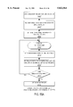
- FIGS. 55(a) and 55(b) are flow charts showing an example of a method for converting between an output format of an emulator and an input method of a simulator and vice versa. This method is preferably performed by mapper element 5406 of FIG. 54.
- FIG. 55(a) shows conversion of emulator data to simulator data. In this example, it is assumed that the emulator data is all read first and then certain emulator data is output to the simulator in accordance with target state names of the simulator read in step 5506. After the simulator data is assembled in successive steps 5512, it is output to the simulator in step 5516. The mapping between the bit order of the emulator and the memory locations of the simulator is performed in accordance with the mapping tables.
- FIG. 55(b) shows conversion of simulator data to emulator data.
- the simulator data is being read in one line at a time.
- certain simulator data is output to the emulator in accordance with target state names of the emulator simulator read in step 5522.
- the emulator data is assembled in successive steps 5530, it is output to the emulator in step 5534.
- the mapping between the bit order of the emulator and the memory locations of the simulator is performed in accordance with the mapping tables. It should be understood that either the sequential reading method or the method of reading all input data before converting could be used in either of FIGS. 55(a) or 55(b).
- FIGS. 56(a) and 56(b) show respective examples of converting between an output format of an emulator and an input method of a simulator and vice versa. Note that one-bit emulator data may be converted to multi-bit simulator data and vice versa. In the described embodiment, mapper 5406 automatically pads with zeroes or divides bytes of data into individual bits as needed.
- the present invention can convert data provided by and required by various types of simulators and emulators.
- the emulator herein were implemented using FPGAs, such an emulator would still be capable of producing an output that could be mapped to an input format used by a simulator.
- the present invention can be used with a emulator implemented in, for example, FPGA technology, in any emulator using programmable chips that implement logic, or in any emulator using reconfigurable logic chips.
Abstract
Description
Claims (2)
Priority Applications (1)
| Application Number | Priority Date | Filing Date | Title |
|---|---|---|---|
| US08/672,762 US5822564A (en) | 1996-06-03 | 1996-06-28 | Checkpointing in an emulation system |
Applications Claiming Priority (2)
| Application Number | Priority Date | Filing Date | Title |
|---|---|---|---|
| US1907896P | 1996-06-03 | 1996-06-03 | |
| US08/672,762 US5822564A (en) | 1996-06-03 | 1996-06-28 | Checkpointing in an emulation system |
Publications (1)
| Publication Number | Publication Date |
|---|---|
| US5822564A true US5822564A (en) | 1998-10-13 |
Family
ID=26691817
Family Applications (1)
| Application Number | Title | Priority Date | Filing Date |
|---|---|---|---|
| US08/672,762 Expired - Lifetime US5822564A (en) | 1996-06-03 | 1996-06-28 | Checkpointing in an emulation system |
Country Status (1)
| Country | Link |
|---|---|
| US (1) | US5822564A (en) |
Cited By (29)
| Publication number | Priority date | Publication date | Assignee | Title |
|---|---|---|---|---|
| US6026230A (en) | 1997-05-02 | 2000-02-15 | Axis Systems, Inc. | Memory simulation system and method |
| US6141636A (en) * | 1997-03-31 | 2000-10-31 | Quickturn Design Systems, Inc. | Logic analysis subsystem in a time-sliced emulator |
| FR2800169A1 (en) * | 1999-10-21 | 2001-04-27 | Bosch Gmbh Robert | Digital logic circuit fault analysis method, creating history of states by cyclically checking internal circuit nodes while inputting standard signals and retracing when halted due to error |
| US20010020224A1 (en) * | 2000-03-02 | 2001-09-06 | Hiroshi Tomita | Logic emulation processor and module unit thereof |
| US6581191B1 (en) | 1999-11-30 | 2003-06-17 | Synplicity, Inc. | Hardware debugging in a hardware description language |
| US6618698B1 (en) | 1999-08-12 | 2003-09-09 | Quickturn Design Systems, Inc. | Clustered processors in an emulation engine |
| US20030188278A1 (en) * | 2002-03-26 | 2003-10-02 | Carrie Susan Elizabeth | Method and apparatus for accelerating digital logic simulations |
| US20040115995A1 (en) * | 2002-11-25 | 2004-06-17 | Sanders Samuel Sidney | Circuit array module |
| US20040148153A1 (en) * | 2003-01-23 | 2004-07-29 | Quickturn Design Systems, Inc. | Memory rewind and reconstruction for hardware emulator |
| US6823497B2 (en) | 1999-11-30 | 2004-11-23 | Synplicity, Inc. | Method and user interface for debugging an electronic system |
| US20050010880A1 (en) * | 1999-11-30 | 2005-01-13 | Bridges2Silicon, Inc. | Method and user interface for debugging an electronic system |
| US20050267728A1 (en) * | 2004-06-01 | 2005-12-01 | Quickturn Design Systems, Inc. | System and method for reliably supporting multiple signaling technologies |
| US20050267732A1 (en) * | 2004-06-01 | 2005-12-01 | Quickturn Design Systems, Inc. | Method of visualization in processor based emulation system |
| US20050265375A1 (en) * | 2004-06-01 | 2005-12-01 | Quayle Barton L | System and method for identifying target systems |
| US20050267727A1 (en) * | 2004-06-01 | 2005-12-01 | Quickturn Design Systems, Inc. | System and method for providing flexible signal routing and timing |
| US20050267729A1 (en) * | 2004-06-01 | 2005-12-01 | Quickturn Design Systems, Inc. | Extensible memory architecture and communication protocol for supporting multiple devices in low-bandwidth, asynchronous applications |
| US20050271078A1 (en) * | 2004-06-01 | 2005-12-08 | Quayle Barton L | System and method for configuring communication systems |
| US20050278163A1 (en) * | 2004-06-01 | 2005-12-15 | Quickturn Design Systems, Inc. | System and method for resolving artifacts in differential signals |
| US7043417B1 (en) | 2000-09-06 | 2006-05-09 | Quickturn Design Systems, Inc. | High speed software driven emulator comprised of a plurality of emulation processors with improved multiplexed data memory |
| US7065481B2 (en) | 1999-11-30 | 2006-06-20 | Synplicity, Inc. | Method and system for debugging an electronic system using instrumentation circuitry and a logic analyzer |
| US7072818B1 (en) | 1999-11-30 | 2006-07-04 | Synplicity, Inc. | Method and system for debugging an electronic system |
| US20070038431A1 (en) * | 2005-08-12 | 2007-02-15 | Arm Limited | Data processing apparatus simulation |
| US7222315B2 (en) | 2000-11-28 | 2007-05-22 | Synplicity, Inc. | Hardware-based HDL code coverage and design analysis |
| US7555424B2 (en) | 2006-03-16 | 2009-06-30 | Quickturn Design Systems, Inc. | Method and apparatus for rewinding emulated memory circuits |
| US8099271B2 (en) | 1999-11-30 | 2012-01-17 | Synopsys, Inc. | Design instrumentation circuitry |
| US8595683B1 (en) | 2012-04-12 | 2013-11-26 | Cadence Design Systems, Inc. | Generating user clocks for a prototyping environment |
| US9069782B2 (en) | 2012-10-01 | 2015-06-30 | The Research Foundation For The State University Of New York | System and method for security and privacy aware virtual machine checkpointing |
| US9767271B2 (en) | 2010-07-15 | 2017-09-19 | The Research Foundation For The State University Of New York | System and method for validating program execution at run-time |
| US9767284B2 (en) | 2012-09-14 | 2017-09-19 | The Research Foundation For The State University Of New York | Continuous run-time validation of program execution: a practical approach |
Citations (46)
| Publication number | Priority date | Publication date | Assignee | Title |
|---|---|---|---|---|
| US3955180A (en) * | 1974-01-02 | 1976-05-04 | Honeywell Information Systems Inc. | Table driven emulation system |
| US4306286A (en) * | 1979-06-29 | 1981-12-15 | International Business Machines Corporation | Logic simulation machine |
| US4357678A (en) * | 1979-12-26 | 1982-11-02 | International Business Machines Corporation | Programmable sequential logic array mechanism |
| US4527249A (en) * | 1982-10-22 | 1985-07-02 | Control Data Corporation | Simulator system for logic design validation |
| US4583169A (en) * | 1983-04-29 | 1986-04-15 | The Boeing Company | Method for emulating a Boolean network system |
| US4587625A (en) * | 1983-07-05 | 1986-05-06 | Motorola Inc. | Processor for simulating digital structures |
| US4656580A (en) * | 1982-06-11 | 1987-04-07 | International Business Machines Corporation | Logic simulation machine |
| US4695968A (en) * | 1983-11-03 | 1987-09-22 | Prime Computer, Inc. | Digital system simulation method and apparatus having improved sampling |
| US4697241A (en) * | 1985-03-01 | 1987-09-29 | Simulog, Inc. | Hardware logic simulator |
| US4769817A (en) * | 1986-01-31 | 1988-09-06 | Zycad Corporation | Concurrent fault simulation for logic designs |
| US4782461A (en) * | 1984-06-21 | 1988-11-01 | Step Engineering | Logical grouping of facilities within a computer development system |
| US4787062A (en) * | 1986-06-26 | 1988-11-22 | Ikos Systems, Inc. | Glitch detection by forcing the output of a simulated logic device to an undefined state |
| US4787061A (en) * | 1986-06-25 | 1988-11-22 | Ikos Systems, Inc. | Dual delay mode pipelined logic simulator |
| US4819150A (en) * | 1985-04-05 | 1989-04-04 | Unisys Corporation | Array for simulating computer functions for large computer systems |
| US4862347A (en) * | 1986-04-22 | 1989-08-29 | International Business Machine Corporation | System for simulating memory arrays in a logic simulation machine |
| US4879646A (en) * | 1986-04-18 | 1989-11-07 | Nec Corporation | Data processing system with a pipelined structure for editing trace memory contents and tracing operations during system debugging |
| US4914612A (en) * | 1988-03-31 | 1990-04-03 | International Business Machines Corporation | Massively distributed simulation engine |
| US4972334A (en) * | 1987-03-13 | 1990-11-20 | Hitachi, Ltd. | Automatic generation method of a simulation program for numerically solving a partial differential equation according to a boundary-fitted method |
| US5031129A (en) * | 1989-05-12 | 1991-07-09 | Alcatel Na Network Systems Corp. | Parallel pseudo-random generator for emulating a serial pseudo-random generator and method for carrying out same |
| US5036473A (en) * | 1988-10-05 | 1991-07-30 | Mentor Graphics Corporation | Method of using electronically reconfigurable logic circuits |
| US5068812A (en) * | 1989-07-18 | 1991-11-26 | Vlsi Technology, Inc. | Event-controlled LCC stimulation |
| US5084824A (en) * | 1990-03-29 | 1992-01-28 | National Semiconductor Corporation | Simulation model generation from a physical data base of a combinatorial circuit |
| US5088033A (en) * | 1986-04-28 | 1992-02-11 | Xerox Corporation | Data processing system emulation in a window with a coprocessor and I/O emulation |
| US5109353A (en) * | 1988-12-02 | 1992-04-28 | Quickturn Systems, Incorporated | Apparatus for emulation of electronic hardware system |
| US5114353A (en) * | 1991-03-01 | 1992-05-19 | Quickturn Systems, Incorporated | Multiple connector arrangement for printed circuit board interconnection |
| US5126966A (en) * | 1986-06-25 | 1992-06-30 | Ikos Systems, Inc. | High speed logic simulation system with stimulus engine using independent event channels selectively driven by independent stimulus programs |
| US5259006A (en) * | 1990-04-18 | 1993-11-02 | Quickturn Systems, Incorporated | Method for substantially eliminating hold time violations in implementing high speed logic circuits or the like |
| US5321828A (en) * | 1991-06-07 | 1994-06-14 | Step Engineering | High speed microcomputer in-circuit emulator |
| US5329470A (en) * | 1988-12-02 | 1994-07-12 | Quickturn Systems, Inc. | Reconfigurable hardware emulation system |
| US5329471A (en) * | 1987-06-02 | 1994-07-12 | Texas Instruments Incorporated | Emulation devices, systems and methods utilizing state machines |
| US5331571A (en) * | 1992-07-22 | 1994-07-19 | Nec Electronics, Inc. | Testing and emulation of integrated circuits |
| US5345580A (en) * | 1990-11-29 | 1994-09-06 | Kabushiki Kaisha Toshiba | Microprocessor device and emulator device thereof |
| US5352123A (en) * | 1992-06-08 | 1994-10-04 | Quickturn Systems, Incorporated | Switching midplane and interconnection system for interconnecting large numbers of signals |
| US5377123A (en) * | 1992-06-08 | 1994-12-27 | Hyman; Edward | Programmable logic device |
| US5386550A (en) * | 1992-01-24 | 1995-01-31 | Fujitsu Limited | Pseudo-LSI device and debugging system incorporating same |
| US5396498A (en) * | 1990-12-07 | 1995-03-07 | Thomson Csf | Integrated circuit with peripheral test controller |
| US5425036A (en) * | 1992-09-18 | 1995-06-13 | Quickturn Design Systems, Inc. | Method and apparatus for debugging reconfigurable emulation systems |
| US5437037A (en) * | 1992-06-05 | 1995-07-25 | Mega Chips Corporation | Simulation using compiled function description language |
| US5448522A (en) * | 1994-03-24 | 1995-09-05 | Quickturn Design Systems, Inc. | Multi-port memory emulation using tag registers |
| US5448496A (en) * | 1988-10-05 | 1995-09-05 | Quickturn Design Systems, Inc. | Partial crossbar interconnect architecture for reconfigurably connecting multiple reprogrammable logic devices in a logic emulation system |
| US5452239A (en) * | 1993-01-29 | 1995-09-19 | Quickturn Design Systems, Inc. | Method of removing gated clocks from the clock nets of a netlist for timing sensitive implementation of the netlist in a hardware emulation system |
| US5475624A (en) * | 1992-04-30 | 1995-12-12 | Schlumberger Technologies, Inc. | Test generation by environment emulation |
| US5475830A (en) * | 1992-01-31 | 1995-12-12 | Quickturn Design Systems, Inc. | Structure and method for providing a reconfigurable emulation circuit without hold time violations |
| US5551013A (en) * | 1994-06-03 | 1996-08-27 | International Business Machines Corporation | Multiprocessor for hardware emulation |
| US5572710A (en) * | 1992-09-11 | 1996-11-05 | Kabushiki Kaisha Toshiba | High speed logic simulation system using time division emulation suitable for large scale logic circuits |
| US5621651A (en) * | 1994-03-09 | 1997-04-15 | Texas Instruments Incorporated | Emulation devices, systems and methods with distributed control of test interfaces in clock domains |
-
1996
- 1996-06-28 US US08/672,762 patent/US5822564A/en not_active Expired - Lifetime
Patent Citations (49)
| Publication number | Priority date | Publication date | Assignee | Title |
|---|---|---|---|---|
| US3955180A (en) * | 1974-01-02 | 1976-05-04 | Honeywell Information Systems Inc. | Table driven emulation system |
| US4306286A (en) * | 1979-06-29 | 1981-12-15 | International Business Machines Corporation | Logic simulation machine |
| US4357678A (en) * | 1979-12-26 | 1982-11-02 | International Business Machines Corporation | Programmable sequential logic array mechanism |
| US4656580A (en) * | 1982-06-11 | 1987-04-07 | International Business Machines Corporation | Logic simulation machine |
| US4527249A (en) * | 1982-10-22 | 1985-07-02 | Control Data Corporation | Simulator system for logic design validation |
| US4583169A (en) * | 1983-04-29 | 1986-04-15 | The Boeing Company | Method for emulating a Boolean network system |
| US4587625A (en) * | 1983-07-05 | 1986-05-06 | Motorola Inc. | Processor for simulating digital structures |
| US4695968A (en) * | 1983-11-03 | 1987-09-22 | Prime Computer, Inc. | Digital system simulation method and apparatus having improved sampling |
| US4725971A (en) * | 1983-11-03 | 1988-02-16 | Prime Computer, Inc. | Digital system simulation method and apparatus |
| US4782461A (en) * | 1984-06-21 | 1988-11-01 | Step Engineering | Logical grouping of facilities within a computer development system |
| US4697241A (en) * | 1985-03-01 | 1987-09-29 | Simulog, Inc. | Hardware logic simulator |
| US4819150A (en) * | 1985-04-05 | 1989-04-04 | Unisys Corporation | Array for simulating computer functions for large computer systems |
| US4769817A (en) * | 1986-01-31 | 1988-09-06 | Zycad Corporation | Concurrent fault simulation for logic designs |
| US4879646A (en) * | 1986-04-18 | 1989-11-07 | Nec Corporation | Data processing system with a pipelined structure for editing trace memory contents and tracing operations during system debugging |
| US4862347A (en) * | 1986-04-22 | 1989-08-29 | International Business Machine Corporation | System for simulating memory arrays in a logic simulation machine |
| US5088033A (en) * | 1986-04-28 | 1992-02-11 | Xerox Corporation | Data processing system emulation in a window with a coprocessor and I/O emulation |
| US5126966A (en) * | 1986-06-25 | 1992-06-30 | Ikos Systems, Inc. | High speed logic simulation system with stimulus engine using independent event channels selectively driven by independent stimulus programs |
| US4787061A (en) * | 1986-06-25 | 1988-11-22 | Ikos Systems, Inc. | Dual delay mode pipelined logic simulator |
| US4787062A (en) * | 1986-06-26 | 1988-11-22 | Ikos Systems, Inc. | Glitch detection by forcing the output of a simulated logic device to an undefined state |
| US4972334A (en) * | 1987-03-13 | 1990-11-20 | Hitachi, Ltd. | Automatic generation method of a simulation program for numerically solving a partial differential equation according to a boundary-fitted method |
| US5329471A (en) * | 1987-06-02 | 1994-07-12 | Texas Instruments Incorporated | Emulation devices, systems and methods utilizing state machines |
| US4914612A (en) * | 1988-03-31 | 1990-04-03 | International Business Machines Corporation | Massively distributed simulation engine |
| US5452231A (en) * | 1988-10-05 | 1995-09-19 | Quickturn Design Systems, Inc. | Hierarchically connected reconfigurable logic assembly |
| US5036473A (en) * | 1988-10-05 | 1991-07-30 | Mentor Graphics Corporation | Method of using electronically reconfigurable logic circuits |
| US5448496A (en) * | 1988-10-05 | 1995-09-05 | Quickturn Design Systems, Inc. | Partial crossbar interconnect architecture for reconfigurably connecting multiple reprogrammable logic devices in a logic emulation system |
| US5109353A (en) * | 1988-12-02 | 1992-04-28 | Quickturn Systems, Incorporated | Apparatus for emulation of electronic hardware system |
| US5329470A (en) * | 1988-12-02 | 1994-07-12 | Quickturn Systems, Inc. | Reconfigurable hardware emulation system |
| US5477475A (en) * | 1988-12-02 | 1995-12-19 | Quickturn Design Systems, Inc. | Method for emulating a circuit design using an electrically reconfigurable hardware emulation apparatus |
| US5031129A (en) * | 1989-05-12 | 1991-07-09 | Alcatel Na Network Systems Corp. | Parallel pseudo-random generator for emulating a serial pseudo-random generator and method for carrying out same |
| US5068812A (en) * | 1989-07-18 | 1991-11-26 | Vlsi Technology, Inc. | Event-controlled LCC stimulation |
| US5084824A (en) * | 1990-03-29 | 1992-01-28 | National Semiconductor Corporation | Simulation model generation from a physical data base of a combinatorial circuit |
| US5259006A (en) * | 1990-04-18 | 1993-11-02 | Quickturn Systems, Incorporated | Method for substantially eliminating hold time violations in implementing high speed logic circuits or the like |
| US5345580A (en) * | 1990-11-29 | 1994-09-06 | Kabushiki Kaisha Toshiba | Microprocessor device and emulator device thereof |
| US5396498A (en) * | 1990-12-07 | 1995-03-07 | Thomson Csf | Integrated circuit with peripheral test controller |
| US5114353A (en) * | 1991-03-01 | 1992-05-19 | Quickturn Systems, Incorporated | Multiple connector arrangement for printed circuit board interconnection |
| US5321828A (en) * | 1991-06-07 | 1994-06-14 | Step Engineering | High speed microcomputer in-circuit emulator |
| US5386550A (en) * | 1992-01-24 | 1995-01-31 | Fujitsu Limited | Pseudo-LSI device and debugging system incorporating same |
| US5475830A (en) * | 1992-01-31 | 1995-12-12 | Quickturn Design Systems, Inc. | Structure and method for providing a reconfigurable emulation circuit without hold time violations |
| US5475624A (en) * | 1992-04-30 | 1995-12-12 | Schlumberger Technologies, Inc. | Test generation by environment emulation |
| US5437037A (en) * | 1992-06-05 | 1995-07-25 | Mega Chips Corporation | Simulation using compiled function description language |
| US5377123A (en) * | 1992-06-08 | 1994-12-27 | Hyman; Edward | Programmable logic device |
| US5352123A (en) * | 1992-06-08 | 1994-10-04 | Quickturn Systems, Incorporated | Switching midplane and interconnection system for interconnecting large numbers of signals |
| US5331571A (en) * | 1992-07-22 | 1994-07-19 | Nec Electronics, Inc. | Testing and emulation of integrated circuits |
| US5572710A (en) * | 1992-09-11 | 1996-11-05 | Kabushiki Kaisha Toshiba | High speed logic simulation system using time division emulation suitable for large scale logic circuits |
| US5425036A (en) * | 1992-09-18 | 1995-06-13 | Quickturn Design Systems, Inc. | Method and apparatus for debugging reconfigurable emulation systems |
| US5452239A (en) * | 1993-01-29 | 1995-09-19 | Quickturn Design Systems, Inc. | Method of removing gated clocks from the clock nets of a netlist for timing sensitive implementation of the netlist in a hardware emulation system |
| US5621651A (en) * | 1994-03-09 | 1997-04-15 | Texas Instruments Incorporated | Emulation devices, systems and methods with distributed control of test interfaces in clock domains |
| US5448522A (en) * | 1994-03-24 | 1995-09-05 | Quickturn Design Systems, Inc. | Multi-port memory emulation using tag registers |
| US5551013A (en) * | 1994-06-03 | 1996-08-27 | International Business Machines Corporation | Multiprocessor for hardware emulation |
Non-Patent Citations (18)
| Title |
|---|
| "Ikos Systems to Acquire Virtual Machine Works", N/A, Mar. 26, 1997, pp. 1 & 2. |
| "Logic Emulation for the Masses Arrives", N/A. |
| "VHDL Mixed-Level Fault Simulator", N/A. |
| "Virtual Wires Published Papers," Various Dates. |
| Agarwal, Anant, "Virtual Wires TM A Technology for Massive Multi-FPGA Systems", Vistual Machine Works (no publication date given). |
| Agarwal, Anant, Virtual Wires TM A Technology for Massive Multi FPGA Systems , Vistual Machine Works (no publication date given). * |
| Goering, R., "Emulation for the Masses", Electronic Engineering Times, Jan. 29, 1996, p. 63. |
| Goering, R., Emulation for the Masses , Electronic Engineering Times, Jan. 29, 1996, p. 63. * |
| Ikos Systems to Acquire Virtual Machine Works , N/A, Mar. 26, 1997, pp. 1 & 2. * |
| Logic Emulation for the Masses Arrives , N/A. * |
| Maliniak, L., "Pin Multiplexing Yields Low-Cost Logic Emulation", Electronic Design, Jan. 22, 1996. |
| Maliniak, L., Pin Multiplexing Yields Low Cost Logic Emulation , Electronic Design, Jan. 22, 1996. * |
| Sim Express TM "Hardware Emulator", Virtual Machine Works pp. 1-24. |
| Sim Express TM Hardware Emulator , Virtual Machine Works pp. 1 24. * |
| VHDL Mixed Level Fault Simulator , N/A. * |
| Virtual Wires Published Papers, Various Dates. * |
| VirtuaLogic SLI Emulation System, "VirtuaLogic SLI", N/A. |
| VirtuaLogic SLI Emulation System, VirtuaLogic SLI , N/A. * |
Cited By (48)
| Publication number | Priority date | Publication date | Assignee | Title |
|---|---|---|---|---|
| US6141636A (en) * | 1997-03-31 | 2000-10-31 | Quickturn Design Systems, Inc. | Logic analysis subsystem in a time-sliced emulator |
| US6026230A (en) | 1997-05-02 | 2000-02-15 | Axis Systems, Inc. | Memory simulation system and method |
| US20030212539A1 (en) * | 1999-08-12 | 2003-11-13 | Quickturn Design Systems, Inc. | Clustered processors in an emulation engine |
| US7047179B2 (en) | 1999-08-12 | 2006-05-16 | Quickturn Design Systems, Inc. | Clustered processors in an emulation engine |
| US6618698B1 (en) | 1999-08-12 | 2003-09-09 | Quickturn Design Systems, Inc. | Clustered processors in an emulation engine |
| FR2800169A1 (en) * | 1999-10-21 | 2001-04-27 | Bosch Gmbh Robert | Digital logic circuit fault analysis method, creating history of states by cyclically checking internal circuit nodes while inputting standard signals and retracing when halted due to error |
| US7065481B2 (en) | 1999-11-30 | 2006-06-20 | Synplicity, Inc. | Method and system for debugging an electronic system using instrumentation circuitry and a logic analyzer |
| US8099271B2 (en) | 1999-11-30 | 2012-01-17 | Synopsys, Inc. | Design instrumentation circuitry |
| US20030182642A1 (en) * | 1999-11-30 | 2003-09-25 | Schubert Nils Endric | Hardware debugging in a hardware description language |
| US7069526B2 (en) | 1999-11-30 | 2006-06-27 | Synplicity, Inc. | Hardware debugging in a hardware description language |
| US6581191B1 (en) | 1999-11-30 | 2003-06-17 | Synplicity, Inc. | Hardware debugging in a hardware description language |
| US6823497B2 (en) | 1999-11-30 | 2004-11-23 | Synplicity, Inc. | Method and user interface for debugging an electronic system |
| US20050010880A1 (en) * | 1999-11-30 | 2005-01-13 | Bridges2Silicon, Inc. | Method and user interface for debugging an electronic system |
| US6904577B2 (en) | 1999-11-30 | 2005-06-07 | Synplicity, Inc. | Hardware debugging in a hardware description language |
| US20050125754A1 (en) * | 1999-11-30 | 2005-06-09 | Schubert Nils E. | Hardware debugging in a hardware description language |
| US7072818B1 (en) | 1999-11-30 | 2006-07-04 | Synplicity, Inc. | Method and system for debugging an electronic system |
| US7356786B2 (en) | 1999-11-30 | 2008-04-08 | Synplicity, Inc. | Method and user interface for debugging an electronic system |
| US7506286B2 (en) | 1999-11-30 | 2009-03-17 | Synopsys, Inc. | Method and system for debugging an electronic system |
| US20010020224A1 (en) * | 2000-03-02 | 2001-09-06 | Hiroshi Tomita | Logic emulation processor and module unit thereof |
| US7043417B1 (en) | 2000-09-06 | 2006-05-09 | Quickturn Design Systems, Inc. | High speed software driven emulator comprised of a plurality of emulation processors with improved multiplexed data memory |
| US7836416B2 (en) | 2000-11-28 | 2010-11-16 | Synopsys, Inc. | Hardware-based HDL code coverage and design analysis |
| US7222315B2 (en) | 2000-11-28 | 2007-05-22 | Synplicity, Inc. | Hardware-based HDL code coverage and design analysis |
| US20030188278A1 (en) * | 2002-03-26 | 2003-10-02 | Carrie Susan Elizabeth | Method and apparatus for accelerating digital logic simulations |
| US20040115995A1 (en) * | 2002-11-25 | 2004-06-17 | Sanders Samuel Sidney | Circuit array module |
| US7440884B2 (en) * | 2003-01-23 | 2008-10-21 | Quickturn Design Systems, Inc. | Memory rewind and reconstruction for hardware emulator |
| US20040148153A1 (en) * | 2003-01-23 | 2004-07-29 | Quickturn Design Systems, Inc. | Memory rewind and reconstruction for hardware emulator |
| US7738398B2 (en) | 2004-06-01 | 2010-06-15 | Quickturn Design Systems, Inc. | System and method for configuring communication systems |
| US20050265375A1 (en) * | 2004-06-01 | 2005-12-01 | Quayle Barton L | System and method for identifying target systems |
| US20050278163A1 (en) * | 2004-06-01 | 2005-12-15 | Quickturn Design Systems, Inc. | System and method for resolving artifacts in differential signals |
| US20050271078A1 (en) * | 2004-06-01 | 2005-12-08 | Quayle Barton L | System and method for configuring communication systems |
| US7440866B2 (en) | 2004-06-01 | 2008-10-21 | Quickturn Design Systems Inc. | System and method for validating an input/output voltage of a target system |
| US20050267729A1 (en) * | 2004-06-01 | 2005-12-01 | Quickturn Design Systems, Inc. | Extensible memory architecture and communication protocol for supporting multiple devices in low-bandwidth, asynchronous applications |
| US20050267727A1 (en) * | 2004-06-01 | 2005-12-01 | Quickturn Design Systems, Inc. | System and method for providing flexible signal routing and timing |
| US20050267728A1 (en) * | 2004-06-01 | 2005-12-01 | Quickturn Design Systems, Inc. | System and method for reliably supporting multiple signaling technologies |
| US7606697B2 (en) | 2004-06-01 | 2009-10-20 | Quickturn Design Systems, Inc. | System and method for resolving artifacts in differential signals |
| US7640155B2 (en) | 2004-06-01 | 2009-12-29 | Quickturn Design Systems, Inc. | Extensible memory architecture and communication protocol for supporting multiple devices in low-bandwidth, asynchronous applications |
| US7721036B2 (en) | 2004-06-01 | 2010-05-18 | Quickturn Design Systems Inc. | System and method for providing flexible signal routing and timing |
| US20050267732A1 (en) * | 2004-06-01 | 2005-12-01 | Quickturn Design Systems, Inc. | Method of visualization in processor based emulation system |
| US7739093B2 (en) | 2004-06-01 | 2010-06-15 | Quickturn Design System, Inc. | Method of visualization in processor based emulation system |
| US7738399B2 (en) | 2004-06-01 | 2010-06-15 | Quickturn Design Systems Inc. | System and method for identifying target systems |
| US20070038431A1 (en) * | 2005-08-12 | 2007-02-15 | Arm Limited | Data processing apparatus simulation |
| US7555424B2 (en) | 2006-03-16 | 2009-06-30 | Quickturn Design Systems, Inc. | Method and apparatus for rewinding emulated memory circuits |
| US9767271B2 (en) | 2010-07-15 | 2017-09-19 | The Research Foundation For The State University Of New York | System and method for validating program execution at run-time |
| US8595683B1 (en) | 2012-04-12 | 2013-11-26 | Cadence Design Systems, Inc. | Generating user clocks for a prototyping environment |
| US9767284B2 (en) | 2012-09-14 | 2017-09-19 | The Research Foundation For The State University Of New York | Continuous run-time validation of program execution: a practical approach |
| US9069782B2 (en) | 2012-10-01 | 2015-06-30 | The Research Foundation For The State University Of New York | System and method for security and privacy aware virtual machine checkpointing |
| US9552495B2 (en) | 2012-10-01 | 2017-01-24 | The Research Foundation For The State University Of New York | System and method for security and privacy aware virtual machine checkpointing |
| US10324795B2 (en) | 2012-10-01 | 2019-06-18 | The Research Foundation for the State University o | System and method for security and privacy aware virtual machine checkpointing |
Similar Documents
| Publication | Publication Date | Title |
|---|---|---|
| US5822564A (en) | Checkpointing in an emulation system | |
| US7260794B2 (en) | Logic multiprocessor for FPGA implementation | |
| US6141636A (en) | Logic analysis subsystem in a time-sliced emulator | |
| US5923865A (en) | Emulation system having multiple emulated clock cycles per emulator clock cycle and improved signal routing | |
| US7185293B1 (en) | Universal hardware device and method and tools for use therewith | |
| US7865346B2 (en) | Instruction encoding in a hardware simulation accelerator | |
| KR20020022061A (en) | Software tool to allow filed programmable system level devices | |
| US9015026B2 (en) | System and method incorporating an arithmetic logic unit for emulation | |
| US7904288B1 (en) | Hardware emulator having a variable input emulation group | |
| KR20030066641A (en) | Hardware-assisted design verification system using a packet-based protocol logic synthesized for efficient data loading and unloading | |
| JP2001249824A (en) | Logical emulation processor and its module unit | |
| JPH04233040A (en) | Simulation system for executing computer program | |
| Huang et al. | A retargetable embedded in-circuit emulation module for microprocessors | |
| CN116306392A (en) | Chip simulation device, method, electronic device and storage medium | |
| Bezerra et al. | A guide to migrating from microprocessor to FPGA coping with the support tool limitations | |
| US20010010034A1 (en) | Simulation of data processing apparatus | |
| US20050228628A1 (en) | System-level simulation of interconnected devices | |
| Ejlali et al. | FPGA-based fault injection into switch-level models | |
| Gonzales | Tool reusable for DSP system emulation and board production testing | |
| Denneau et al. | Design and implementation of a software simulation engine | |
| Schnerr et al. | Instruction set emulation for rapid prototyping of SoCs | |
| Cao | A serial communication-based FPGA co-emulation test bench [D] | |
| Juntunen | Performance testing of RISC-V cores using cycle-accurate software simulations | |
| Brown et al. | Rapid prototyping and evaluation of high-performance computers | |
| Pu et al. | Sphinx: A Hybrid Boolean Processor-FPGA Hardware Emulation System |
Legal Events
| Date | Code | Title | Description |
|---|---|---|---|
| AS | Assignment |
Owner name: SYNOPSYS, INCORPORATED, CALIFORNIA Free format text: ASSIGNMENT OF ASSIGNORS INTEREST;ASSIGNORS:CHILTON, JOHN;SARNO, TONY;SCHAEFER, INGO;REEL/FRAME:008232/0693;SIGNING DATES FROM 19960904 TO 19960916 |
|
| AS | Assignment |
Owner name: QUICKTURN DESIGN SYSTEMS, INC., CALIFORNIA Free format text: ASSIGNMENT OF ASSIGNORS INTEREST;ASSIGNOR:SYNOPSYS, INC.;REEL/FRAME:008644/0818 Effective date: 19970702 |
|
| STCF | Information on status: patent grant |
Free format text: PATENTED CASE |
|
| FPAY | Fee payment |
Year of fee payment: 4 |
|
| FPAY | Fee payment |
Year of fee payment: 8 |
|
| FPAY | Fee payment |
Year of fee payment: 12 |
|
| AS | Assignment |
Owner name: CADENCE DESIGN SYSTEMS, INC., CALIFORNIA Free format text: ASSIGNMENT OF ASSIGNORS INTEREST;ASSIGNOR:QUICKTURN DESIGN SYSTEMS, INC.;REEL/FRAME:027789/0450 Effective date: 20120227 |