US5815002A - Method and device of testing semiconductor integrated circuit chip capable of preventing electron-hole pairs - Google Patents
Method and device of testing semiconductor integrated circuit chip capable of preventing electron-hole pairs Download PDFInfo
- Publication number
- US5815002A US5815002A US08/653,834 US65383496A US5815002A US 5815002 A US5815002 A US 5815002A US 65383496 A US65383496 A US 65383496A US 5815002 A US5815002 A US 5815002A
- Authority
- US
- United States
- Prior art keywords
- integrated circuit
- semiconductor integrated
- circuit chip
- wave beam
- current
- Prior art date
- Legal status (The legal status is an assumption and is not a legal conclusion. Google has not performed a legal analysis and makes no representation as to the accuracy of the status listed.)
- Expired - Fee Related
Links
Images


Classifications
-
- G—PHYSICS
- G01—MEASURING; TESTING
- G01R—MEASURING ELECTRIC VARIABLES; MEASURING MAGNETIC VARIABLES
- G01R31/00—Arrangements for testing electric properties; Arrangements for locating electric faults; Arrangements for electrical testing characterised by what is being tested not provided for elsewhere
- G01R31/28—Testing of electronic circuits, e.g. by signal tracer
- G01R31/302—Contactless testing
- G01R31/303—Contactless testing of integrated circuits
Definitions
- the invention relates to a method and a device of testing a semiconductor integrated circuit chip, and more particularly to a method and a device which detect a change of a current or a voltage in a semiconductor integrated circuit chip.
- R represents a resistance of the circuit when the chip is not supplied with the beam
- ⁇ R represents a change of the resistance of the circuit when the chip is supplied with the beam
- heated I represents a current of the circuit when the chip is not supplied with the beam.
- R is constant. Therefore, it is possible to detect a product of ⁇ R and I by detecting ⁇ I. In addition, it is possible to detect ⁇ R when I is constant. Also, it is possible to detect I when ⁇ R is constant.
- a first conventional method or device is disclosed in Japanese Unexamined Patent Prepublication (Kokai) No. 300824/1994.
- This first conventional method comprises a fist step of projecting the beam on the chip during scanning the beam while a constant voltage is supplied to the circuit, and a simultaneous second step of detecting a change of a current in the circuit.
- a second conventional method is disclosed in Japanese Patent Application No. 230672/1994. This second conventional method detects I when ⁇ R is constant. A signal detected by the first and second conventional methods is hereinafter called BIRCH signal.
- a third conventional method is disclosed in Publication of Extended Abstracts (The 55th Autumn Meeting, 1994); The Japan Society of Applied Physics; 22a-ZP 10, p. 586 of Koyama et al.
- This third conventional method is called an NBOBIC method.
- This third conventional method comprises a step of projecting a laser beam on the chip; and a simultaneous step of detecting a current of the chip while the chip is supplied with the laser beam. If there is a fault that the chip, e.g., in Al interconnects, has voids, thermoelectric powers in the portions of the chip that has voids are different. As a result, thermoelectricmotives causes by differences of thermoelectric powers. Therefore, this conventional method detects changes of currents in the circuit that are caused by the thermoelectricmotives.
- a signal detected by the third conventional method is hereinafter called NBOBIC signal.
- the conventional methods for using the laser beam or the electron beam have a disadvantage in that currents are generated in the chip because electron-hole pairs are generated in a semiconductor in a substrate of the chip.
- a signal of the current generated by the electron-hole pair is hereinafter called OBIC signal.
- the OBIC signal is overlapped to the BIRCH signal.
- the OBIC signal is stronger than the BIRCH signal.
- the conventional methods have a dynamic range which has not a width that is capable of amplifying both the OBIC signal and the BIRCH signal. Therefore, inasmuch as the conventional methods are incapable of distinguishing between the OBIC signal and the BIRCH signal, the conventional methods are incapable of detecting the BIRCH signal. Similarly, the conventional methods are incapable of detecting the NBOBIC signal.
- the conventional methods are incapable of distinguishing between a EBIC(Electron Beam Induced Current) signal and the BIRCH(and NBEBIC) signal, the conventional methods are incapable of detecting the BIRCH(and NBEBIC) signal.
- the conventional methods for using the ion beam have a disadvantage in that the ion beam sputters the chip to destroy the chip.
- a method of testing a semiconductor integrated circuit chip that comprises the steps of:
- a method of testing a semiconductor integrated circuit chip that comprises the steps of:
- a method of testing a semiconductor integrated circuit chip that comprises the steps of:
- a method of testing a semiconductor integrated circuit chip that comprises the steps of:
- a device of testing a semiconductor integrated circuit chip comprising:
- voltage supplying means for supplying a voltage to a semiconductor integrated circuit in a semiconductor integrated circuit chip
- supersonic wave beam projecting means for projecting a supersonic wave beam on the semiconductor integrated circuit chip
- current change detecting means for detecting a change of a current in the semiconductor integrated circuit.
- a device of testing a semiconductor integrated circuit chip comprising:
- supersonic wave beam projecting means for projecting a supersonic wave beam on a semiconductor integrated circuit chip
- current change detecting means for detecting a change of a current in a semiconductor integrated circuit in the semiconductor integrated circuit chip.
- a device of testing a semiconductor integrated circuit chip comprising:
- voltage change detecting means for detecting a change of a voltage which is appeared between two ones of terminals of the semiconductor integrated circuit.
- a device of testing a semiconductor integrated circuit chip comprising:
- supersonic wave beam projecting means for projecting a supersonic wave beam on the semiconductor integrated circuit chip
- voltage change detecting means for detecting a change of a voltage which is appeared between two ones of terminals of a semiconductor integrated circuit in the semiconductor integrated circuit chip.
- FIG. 1 is a flow chart for use in describing a method of testing a semiconductor integrated circuit chip according to a first embodiment of the invention
- FIG. 2 is a schematic perspective view for use in describing the method of testing a semiconductor integrated circuit chip according to the first embodiment of the invention
- FIG. 3 is a view of a semiconductor integrated circuit chip testing device according to a second embodiment of the invention.
- FIG. 4 is a flow chart for use in describing a method of testing a semiconductor integrated circuit chip according to a third embodiment of the invention.
- FIG. 5 is a flow chart for use in describing a method of testing a semiconductor integrated circuit chip according to a fourth embodiment of the invention.
- FIG. 6 is a flow chart for use in describing a method of testing a semiconductor integrated circuit chip according to a fifth embodiment of the invention.
- FIG. 7 is a schematic perspective view for use in describing a method of testing a semiconductor integrated circuit chip according to the fifth embodiment of the invention.
- FIG. 8 is another schematic perspective view for use in describing a method of testing a semiconductor integrated circuit chip according to the fifth embodiment of the invention.
- FIG. 9 is a view of a semiconductor integrated circuit chip testing device according to a sixth embodiment of the invention.
- FIG. 10 is a flow chart for use in describing a method of testing a semiconductor integrated circuit chip according to a seventh embodiment of the invention.
- FIG. 11 is a schematic perspective view for use in describing a method of testing a semiconductor integrated circuit chip according to the seventh embodiment of the invention.
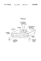
- FIG. 12 is a view of a semiconductor integrated circuit chip testing device according to an eighth embodiment of the invention.
- FIG. 13 is a flow chart for use in describing a method of testing a semiconductor integrated circuit chip according to a ninth embodiment of the invention.
- FIG. 14 is a schematic perspective view for use in describing a method of testing a semiconductor integrated circuit chip according to the ninth embodiment of the invention.
- FIG. 15 is another schematic perspective view for use in describing a method of testing a semiconductor integrated circuit chip according to the ninth embodiment of the invention.
- FIG. 16 a view of a semiconductor integrated circuit chip testing device according to a tenth embodiment of the invention.
- FIGS. 1 and 2 the description will proceed to a method of testing a semiconductor integrated circuit chip according to a first embodiment of the invention.
- a constant voltage source 1 supplies a voltage to a semiconductor integrated circuit (not shown) in a semiconductor integrated circuit chip 2 which is supported by a package 3.
- the constant voltage source 1 is connected to a source terminal 4 attached to the package 3.
- a supersonic acoustic wave beam producing device projects a supersonic wave beam 5 on the semiconductor integrated circuit chip 2 while the voltage is supplied to a semiconductor integrated circuit in the semiconductor integrated circuit chip 2.
- liquid such as water 6 that transfers supersonic acoustic wave beam is held by surface tension on a surface of the semiconductor integrated circuit chip 2.
- the water 6 is dropped on surface. of the semiconductor integrated circuit chip 2 by using a filler.
- the semiconductor integrated circuit chip 2 is positioned in the atmosphere.
- a current detecting device 7 detects a change of a current which flows out from a ground terminal 8 of the semiconductor integrated circuit.
- the current detecting device 7 may detect a change of a current which flows in the source terminal 4 or a signal terminal. Inasmuch as a total current in the semiconductor integrated circuit flows out from a ground terminal 8, the current detecting device 7 preferably detects the change of the current which flows out from the ground terminal 8 when an output terminal is opened, namely, is not connected to a load.
- thermoelectric power in the portion of the semiconductor integrated circuit chip 2 when a portion of the semiconductor integrated circuit chip 2 is supplied with the supersonic acoustic wave beam 5, a thermoelectric power of the portion becomes active to cause a potential difference. Therefore, the method detects the change of the current which is caused by the potential difference. The current is transiently caused. If the chips 2 has a fault that the chip 2 has voids and Si nodules, thermoelectric power in the portion of the chip 2 that has voids and Si nodules changes. As a result, thermoelectric power in the portion of the chip 2 that has voids and Si nodules is difference from that in the portion of the chip 2 that has no voids and no Si nodules. Accordingly, the method detects the change of the current to detect the fault of chip 2.
- the semiconductor integrated circuit chip testing device comprises a supersonic acoustic wave beam producing device 9, a supersonic acoustic wave beam lens 10, a sample stand 11, the constant voltage source 1, the current detecting device 7, a system controlling and signal processing device 12, an image and wave displaying device 13, and a test pattern producing device 14.
- the semiconductor integrated circuit chip 2 and the package 3 is set on the sample stand 11.
- the water 6 is held on the surface of the semiconductor integrated circuit chip 2 which is positioned in the atmosphere.
- the sample stand 11 is movable in X-axis, Y-axis, and Z-axis directions.
- the supersonic acoustic wave beam producing device 9 produces the supersonic acoustic wave beam which has a frequency of 1 to 3 GHz.
- the supersonic acoustic wave beam has a wavelength of 0.5 to 1.5 ⁇ m in the water 6.
- the supersonic acoustic wave beam lens 10 convergence the supersonic acoustic wave beam from the supersonic acoustic wave beam producing device 9.
- the system controlling and signal processing device 12 controls a system and processes obtained signals.
- the image and wave displaying device 13 displays current images, fault images, and current wave forms.
- the test pattern producing device 14 produces a test pattern signal which sets a specific state of the semiconductor integrated circuit.
- the supersonic acoustic wave beam producing device 9 projects a supersonic acoustic wave beam 5 on the semiconductor integrated circuit chip 2 while the voltage is supplied from the constant voltage source 1 to a semiconductor integrated circuit in the semiconductor integrated circuit chip 2 and while the sample stand 11 is moved and stopped.
- the supersonic acoustic wave beam 5 is scanned on an area of the semiconductor integrated circuit chip 2 that is observed.
- the supersonic acoustic wave beam 5 is projected to a point of the semiconductor integrated circuit chip 2 that is observed.
- the test pattern producing device 14 supplies the test pattern signal to the semiconductor integrated circuit.
- FIG. 4 shows the method for displaying current images and fault images by using the device.
- the device digitally scans the supersonic acoustic wave beam 5 on the area of the semiconductor integrated circuit chip 2 that is observed. In this event, the device digitally scans the supersonic acoustic wave beam 5 at points of 262,144 in the area that is a product of 512 (lengthwise) and 512 (crosswise).
- a stopping time period in which the supersonic acoustic wave beam 5 is stopped at each of the points is 2 ⁇ s.
- a time period in which the device digitally once scans the supersonic acoustic wave beam 5 on the area is 0.5 second.
- the current detecting device 7 detects a change of a current at each of the points of the area in the stopping time period to converts the change of the current into a detected voltage.
- the system controlling and signal processing device 12 converts the detected voltages into digital detected voltages which has bits of 8 and gradations of 256. The system controlling and signal processing device 12 memorizes the digital detected voltages in memory addresses which correspond to the points of the area.
- step S14 the system controlling and signal processing device 12 judges whether or not the device scans the supersonic acoustic wave beam 5 on whole of the area.
- the step S14 is followed by a step S15. Otherwise, the step S14 returns to the step S12.
- the image and wave displaying device 13 displays the digital detected voltages in memory addresses as brilliance or false colors which has gradations of 256.
- FIG. 5 shows the method for displaying current wave forms by using the device.
- the device irradiates, as pulses, the supersonic acoustic wave beam 5 on the point of the semiconductor integrated circuit chip 2 that is observed.
- Each of the pulses has a period of 2 ⁇ s and a pulse width of 1 ⁇ s.
- the current detecting device 7 detects a change of a current at each of the pulses to converts the change of the current into a detected voltage.
- the system controlling and signal processing device 12 converts the detected voltages into digital detected voltages which has bits of 8 and gradations of 256. The system controlling and signal processing device 12 memorizes the digital detected voltages in memory addresses which correspond to the pulses.
- a step S24 the system controlling and signal processing device 12 judges whether or not the device irradiates the supersonic wave beam 5 at a predetermined time period.
- the step S24 is followed by a step S25. Otherwise, the step S24 returns to the step S22.
- the image and wave displaying device 13 plots the digital detected voltages at time points corresponding to the memory addresses in a coordinates which represents a time points in lateral axis and a voltage a longitudinal axis.
- the current wave form is obtained by representing the digital detected voltages as detected current values.
- the device has a high resolution.
- the device synchronizes a repeat of operation of the step S22 to S24 with the period of the detected current values to add the digital detected voltages in a same phase to produce and memorize added voltages. Thereby, it is possible to improve the S/N.
- a supersonic acoustic wave beam producing device projects a supersonic acoustic wave beam 5 on the semiconductor integrated circuit chip 2.
- a current detecting device 7 detects a change of a current which flows out from a ground terminal 8 of the semiconductor integrated circuit while the semiconductor integrated circuit chip 2 is supplied with the supersonic acoustic wave beam 5 and while the source terminal 4 is connected to ground. As shown FIG. 8, in this event, the source terminal 4 may not be connected to ground.
- FIGS. 6, 7, and 8 is similar to the method of FIGS. 1 and 2 except the constant voltage source 1.
- the current detecting device 7 may detect a change of a current which flows in the source terminal 4 or a signal terminal. Inasmuch as a total current in the semiconductor integrated circuit flows out from the ground terminal 8, the current detecting device 7 preferably detects the change of the current which flows out from the ground terminal 8 when an output terminal is opened, namely, is not connected to a load.
- the semiconductor integrated circuit chip testing device comprises the supersonic acoustic wave beam producing device 9, the supersonic acoustic wave beam lens 10, the sample stand 11, the current detecting device 7, the system controlling and signal processing device 12, and the image and wave displaying device 13.
- the device of FIG. 9 carries out operation of the device of FIG. 3 that is shown in FIG. 4.
- a device for carrying out the method of FIGS. 6, 7, and 8 may comprise the similar parts of the device of FIG. 3. In this event, the device is used when the current detecting device 7 detects a small change of current which flows out from the ground terminal 8 of the semiconductor integrated circuit while the chip 2 is supplied with the supersonic acoustic wave beam 5.
- a constant current source 15 supplies a current to the semiconductor integrated circuit in the semiconductor integrated circuit chip 2.
- a supersonic acoustic wave beam producing device projects a supersonic acoustic wave beam 5 on the semiconductor integrated circuit chip 2 while the current is supplied to a semiconductor integrated circuit in the semiconductor integrated circuit chip 2.
- a voltage detecting device 16 detects a change of a voltage which is supplied between a source terminal 4 and the ground terminal 8 of the semiconductor integrated circuit while the semiconductor integrated circuit chip 2 is supplied with the supersonic acoustic wave beam 5.
- the change of the voltage ( ⁇ V) is defined by an equation (2).
- ⁇ R represents a change of resistance of the circuit when the chip 2 is supplied with the supersonic acoustic wave beam 5 and I represents a current of the circuit when the chip 2 is not supplied with the supersonic acoustic wave beam 5.
- the method can detect not only the fault such as voids of the chip 2 but also the current while the semiconductor integrated circuit chip 2 is supplied with the supersonic acoustic wave beam 5.
- the semiconductor integrated circuit chip testing device comprises the supersonic acoustic wave beam producing device 9, the supersonic acoustic wave beam lens 10, the sample stand 11, the constant current source 15, the voltage detecting device 16, the system controlling and signal processing device 12, and the image and wave displaying device 13.
- the device of FIG. 12 carries out operation of the method of FIGS. 10 and 11.
- a supersonic acoustic wave beam producing device (not shown) project a supersonic acoustic wave beam 5 on the semiconductor integrated circuit chip 2.
- the voltage detecting device 16 detects a change of a voltage which is supplied between the source terminal 4 and the ground terminal 8 of the semiconductor integrated circuit while the semiconductor integrated circuit chip 2 is supplied with the supersonic acoustic wave beam 5 and while the ground terminal 8 is connected to ground. As shown FIG. 15, in this event, the ground terminal 8 may not be connected to ground.
- FIGS. 13, 14, and 15 is similar to the method of FIGS. 10 and 11 except the constant current source 15.
- the semiconductor integrated circuit chip testing device comprises the supersonic acoustic wave beam producing device 9, the supersonic acoustic wave beam lens 10, the sample stand 11, the voltage detecting device 16, the system controlling and signal processing device 12, and the image and wave displaying device 13.
- the device of FIG. 16 carries out operation of the method of FIGS. 13, 14, and 15.
- a device for carrying out the method of FIGS. 13, 14, and 15 may comprise the similar parts of the device of FIG. 12. In this event, the device is used when the voltage detecting device 16 detects a small change of voltage which is supplied between the source terminal 4 and the ground terminal 8 of the semiconductor integrated circuit while the chip 2 is supplied with the supersonic acoustic wave beam 5.
Abstract
A supersonic wave beam producing device projects a supersonic wave beam 5 on a semiconductor integrated circuit chip 2 while a voltage is supplied to a semiconductor integrated circuit in the chip from a constant voltage source 1. A current detecting device 7 detects a change of a current in the circuit while the chip is supplied with the supersonic wave beam. In this event, the constant voltage source may be omitted. A supersonic wave beam producing device may project a supersonic wave beam 5 on a semiconductor integrated circuit chip 2 while a current is supplied to a semiconductor integrated circuit. In this event, a voltage detecting device detects a change of a voltage between two ones of terminals of the circuit.
Description
The invention relates to a method and a device of testing a semiconductor integrated circuit chip, and more particularly to a method and a device which detect a change of a current or a voltage in a semiconductor integrated circuit chip.
Conventional methods and devices of the type described are based a following principle. When a constant voltage is supplied between two ones of terminals of a semiconductor integrated circuit, and when a beam such as a laser beam, electron beam, or a ion beam is projected to the semiconductor integrated circuit chip, a change of a current in the semiconductor integrated circuit is caused by a change of a temperature caused by beam irradiation and heating of the semiconductor integrated circuit. The change of the current (ΔI) is defined by an equation (1).
ΔI=(ΔR/R)I (1)
In the equation (1), R represents a resistance of the circuit when the chip is not supplied with the beam, ΔR represents a change of the resistance of the circuit when the chip is supplied with the beam, and heated I represents a current of the circuit when the chip is not supplied with the beam.
In this event, R is constant. Therefore, it is possible to detect a product of ΔR and I by detecting ΔI. In addition, it is possible to detect ΔR when I is constant. Also, it is possible to detect I when ΔR is constant.
A first conventional method or device is disclosed in Japanese Unexamined Patent Prepublication (Kokai) No. 300824/1994. This first conventional method comprises a fist step of projecting the beam on the chip during scanning the beam while a constant voltage is supplied to the circuit, and a simultaneous second step of detecting a change of a current in the circuit.
When conditions of the beams are same and when qualities of the material portions of the chip supplied with the beam are same, differences of ΔR in the portions of the chip are caused by differences of heat conduction in the portions of the chip. If there is a fault that the chip has voids and Si nodules, heat conduction in the portions of the chip, e.g., in Al interconnects, that has voids and Si nodules are different. Therefore, this conventional method detects a change of a current in the circuit to detect voids and Si nodules in the portions of the chip, e.g., in Al interconnects.
A second conventional method is disclosed in Japanese Patent Application No. 230672/1994. This second conventional method detects I when ΔR is constant. A signal detected by the first and second conventional methods is hereinafter called BIRCH signal.
A third conventional method is disclosed in Publication of Extended Abstracts (The 55th Autumn Meeting, 1994); The Japan Society of Applied Physics; 22a-ZP 10, p. 586 of Koyama et al. This third conventional method is called an NBOBIC method. This third conventional method comprises a step of projecting a laser beam on the chip; and a simultaneous step of detecting a current of the chip while the chip is supplied with the laser beam. If there is a fault that the chip, e.g., in Al interconnects, has voids, thermoelectric powers in the portions of the chip that has voids are different. As a result, thermoelectricmotives causes by differences of thermoelectric powers. Therefore, this conventional method detects changes of currents in the circuit that are caused by the thermoelectricmotives. A signal detected by the third conventional method is hereinafter called NBOBIC signal.
However, the conventional methods for using the laser beam or the electron beam have a disadvantage in that currents are generated in the chip because electron-hole pairs are generated in a semiconductor in a substrate of the chip.
A signal of the current generated by the electron-hole pair is hereinafter called OBIC signal. The OBIC signal is overlapped to the BIRCH signal. In addition, the OBIC signal is stronger than the BIRCH signal. Also, the conventional methods have a dynamic range which has not a width that is capable of amplifying both the OBIC signal and the BIRCH signal. Therefore, inasmuch as the conventional methods are incapable of distinguishing between the OBIC signal and the BIRCH signal, the conventional methods are incapable of detecting the BIRCH signal. Similarly, the conventional methods are incapable of detecting the NBOBIC signal. In addition, inasmuch as the conventional methods are incapable of distinguishing between a EBIC(Electron Beam Induced Current) signal and the BIRCH(and NBEBIC) signal, the conventional methods are incapable of detecting the BIRCH(and NBEBIC) signal.
Also, the conventional methods for using the ion beam have a disadvantage in that the ion beam sputters the chip to destroy the chip.
Accordingly, it is an object of the invention to provide a method and a device of testing a semiconductor integrated circuit chip that does not generate the electron-hole pairs in the semiconductor integrated circuit chip.
It is another object of the invention to provide a method and a device of testing a semiconductor integrated circuit chip that does not destroy the semiconductor integrated circuit chip.
Other objects of the invention will become clear as the description proceeds.
According to a first aspect of the invention, there is provided a method of testing a semiconductor integrated circuit chip that comprises the steps of:
projecting a supersonic acoustic wave beam on the semiconductor integrated circuit chip while a voltage is supplied to a semiconductor integrated circuit in the semiconductor integrated circuit chip; and
detecting a change of a current in the semiconductor integrated circuit while the semiconductor integrated circuit chip is supplied with the supersonic wave beam.
According to a second aspect of the invention, there is provided a method of testing a semiconductor integrated circuit chip that comprises the steps of:
projecting a supersonic wave beam on the semiconductor integrated circuit chip; and
detecting a change of a current in a semiconductor integrated circuit in the semiconductor integrated circuit chip while the semiconductor integrated circuit chip is supplied with the supersonic wave beam.
According to a third aspect of the invention, there is provided a method of testing a semiconductor integrated circuit chip that comprises the steps of:
projecting a supersonic wave beam on the semiconductor integrated circuit chip while a current is supplied to a semiconductor integrated circuit in the semiconductor integrated circuit chip; and
is detecting a change of a voltage which is appeared between two ones of terminals of the semiconductor integrated circuit while the semiconductor integrated circuit chip is supplied with the supersonic wave beam.
According to a fourth aspect of the invention, there is provided a method of testing a semiconductor integrated circuit chip that comprises the steps of:
projecting a supersonic wave beam on the semiconductor integrated circuit chip; and
detecting a change of a voltage which is appeared between two ones of terminals of a semiconductor integrated circuit in the semiconductor integrated circuit chip while the semiconductor integrated circuit chip is supplied with the supersonic wave beam.
According to a fifth aspect of the invention, there is provided a device of testing a semiconductor integrated circuit chip comprising:
voltage supplying means for supplying a voltage to a semiconductor integrated circuit in a semiconductor integrated circuit chip;
supersonic wave beam projecting means for projecting a supersonic wave beam on the semiconductor integrated circuit chip; and
current change detecting means for detecting a change of a current in the semiconductor integrated circuit.
According to a sixth aspect of the invention, there is provided a device of testing a semiconductor integrated circuit chip comprising:
supersonic wave beam projecting means for projecting a supersonic wave beam on a semiconductor integrated circuit chip; and
current change detecting means for detecting a change of a current in a semiconductor integrated circuit in the semiconductor integrated circuit chip.
According to a seventh aspect of the invention, there is provided a device of testing a semiconductor integrated circuit chip comprising:
current supplying means for supplying a current to a semiconductor integrated circuit in a semiconductor integrated circuit chip; supersonic wave beam projecting means for projecting a supersonic wave beam on the semiconductor integrated circuit chip; and
voltage change detecting means for detecting a change of a voltage which is appeared between two ones of terminals of the semiconductor integrated circuit.
According to an eighth aspect of the invention, there is provided a device of testing a semiconductor integrated circuit chip comprising:
supersonic wave beam projecting means for projecting a supersonic wave beam on the semiconductor integrated circuit chip; and
voltage change detecting means for detecting a change of a voltage which is appeared between two ones of terminals of a semiconductor integrated circuit in the semiconductor integrated circuit chip.
The invention will be explained in more in detail in conjunction with appended drawings, wherein:
FIG. 1 is a flow chart for use in describing a method of testing a semiconductor integrated circuit chip according to a first embodiment of the invention;
FIG. 2 is a schematic perspective view for use in describing the method of testing a semiconductor integrated circuit chip according to the first embodiment of the invention;
FIG. 3 is a view of a semiconductor integrated circuit chip testing device according to a second embodiment of the invention;
FIG. 4 is a flow chart for use in describing a method of testing a semiconductor integrated circuit chip according to a third embodiment of the invention;
FIG. 5 is a flow chart for use in describing a method of testing a semiconductor integrated circuit chip according to a fourth embodiment of the invention;
FIG. 6 is a flow chart for use in describing a method of testing a semiconductor integrated circuit chip according to a fifth embodiment of the invention;
FIG. 7 is a schematic perspective view for use in describing a method of testing a semiconductor integrated circuit chip according to the fifth embodiment of the invention;
FIG. 8 is another schematic perspective view for use in describing a method of testing a semiconductor integrated circuit chip according to the fifth embodiment of the invention;
FIG. 9 is a view of a semiconductor integrated circuit chip testing device according to a sixth embodiment of the invention;
FIG. 10 is a flow chart for use in describing a method of testing a semiconductor integrated circuit chip according to a seventh embodiment of the invention;
FIG. 11 is a schematic perspective view for use in describing a method of testing a semiconductor integrated circuit chip according to the seventh embodiment of the invention;
FIG. 12 is a view of a semiconductor integrated circuit chip testing device according to an eighth embodiment of the invention;
FIG. 13 is a flow chart for use in describing a method of testing a semiconductor integrated circuit chip according to a ninth embodiment of the invention;
FIG. 14 is a schematic perspective view for use in describing a method of testing a semiconductor integrated circuit chip according to the ninth embodiment of the invention;
FIG. 15 is another schematic perspective view for use in describing a method of testing a semiconductor integrated circuit chip according to the ninth embodiment of the invention; and
FIG. 16 a view of a semiconductor integrated circuit chip testing device according to a tenth embodiment of the invention.
Referring to FIGS. 1 and 2, the description will proceed to a method of testing a semiconductor integrated circuit chip according to a first embodiment of the invention.
At a step S1, a constant voltage source 1 supplies a voltage to a semiconductor integrated circuit (not shown) in a semiconductor integrated circuit chip 2 which is supported by a package 3. The constant voltage source 1 is connected to a source terminal 4 attached to the package 3.
Next, at a step S2, a supersonic acoustic wave beam producing device (not shown) projects a supersonic wave beam 5 on the semiconductor integrated circuit chip 2 while the voltage is supplied to a semiconductor integrated circuit in the semiconductor integrated circuit chip 2. In this event, liquid such as water 6 that transfers supersonic acoustic wave beam is held by surface tension on a surface of the semiconductor integrated circuit chip 2. For example, the water 6 is dropped on surface. of the semiconductor integrated circuit chip 2 by using a filler. Also, in this event, the semiconductor integrated circuit chip 2 is positioned in the atmosphere.
Next, at a step S3, a current detecting device 7 detects a change of a current which flows out from a ground terminal 8 of the semiconductor integrated circuit. The current detecting device 7 may detect a change of a current which flows in the source terminal 4 or a signal terminal. Inasmuch as a total current in the semiconductor integrated circuit flows out from a ground terminal 8, the current detecting device 7 preferably detects the change of the current which flows out from the ground terminal 8 when an output terminal is opened, namely, is not connected to a load.
In the method, when a portion of the semiconductor integrated circuit chip 2 is supplied with the supersonic acoustic wave beam 5, a thermoelectric power of the portion becomes active to cause a potential difference. Therefore, the method detects the change of the current which is caused by the potential difference. The current is transiently caused. If the chips 2 has a fault that the chip 2 has voids and Si nodules, thermoelectric power in the portion of the chip 2 that has voids and Si nodules changes. As a result, thermoelectric power in the portion of the chip 2 that has voids and Si nodules is difference from that in the portion of the chip 2 that has no voids and no Si nodules. Accordingly, the method detects the change of the current to detect the fault of chip 2.
Referring to FIG. 3, the description will proceed to a semiconductor integrated circuit chip testing device according to a second embodiment of the invention.
The semiconductor integrated circuit chip testing device comprises a supersonic acoustic wave beam producing device 9, a supersonic acoustic wave beam lens 10, a sample stand 11, the constant voltage source 1, the current detecting device 7, a system controlling and signal processing device 12, an image and wave displaying device 13, and a test pattern producing device 14.
The semiconductor integrated circuit chip 2 and the package 3 is set on the sample stand 11. The water 6 is held on the surface of the semiconductor integrated circuit chip 2 which is positioned in the atmosphere. The sample stand 11 is movable in X-axis, Y-axis, and Z-axis directions.
The supersonic acoustic wave beam producing device 9 produces the supersonic acoustic wave beam which has a frequency of 1 to 3 GHz. The supersonic acoustic wave beam has a wavelength of 0.5 to 1.5 μm in the water 6. The supersonic acoustic wave beam lens 10 convergence the supersonic acoustic wave beam from the supersonic acoustic wave beam producing device 9. The system controlling and signal processing device 12 controls a system and processes obtained signals. The image and wave displaying device 13 displays current images, fault images, and current wave forms. The test pattern producing device 14 produces a test pattern signal which sets a specific state of the semiconductor integrated circuit.
The supersonic acoustic wave beam producing device 9 projects a supersonic acoustic wave beam 5 on the semiconductor integrated circuit chip 2 while the voltage is supplied from the constant voltage source 1 to a semiconductor integrated circuit in the semiconductor integrated circuit chip 2 and while the sample stand 11 is moved and stopped.
When we observe current images and fault images by using the device, the supersonic acoustic wave beam 5 is scanned on an area of the semiconductor integrated circuit chip 2 that is observed. When we observe a current wave form by using the device, the supersonic acoustic wave beam 5 is projected to a point of the semiconductor integrated circuit chip 2 that is observed, When we observe current wave forms, current images, and fault images by using the device, the test pattern producing device 14 supplies the test pattern signal to the semiconductor integrated circuit.
Referring to FIG. 4, the description will proceed to a method of testing a semiconductor integrated circuit chip according to a third embodiment of the invention.
FIG. 4 shows the method for displaying current images and fault images by using the device. At a step S11, the device digitally scans the supersonic acoustic wave beam 5 on the area of the semiconductor integrated circuit chip 2 that is observed. In this event, the device digitally scans the supersonic acoustic wave beam 5 at points of 262,144 in the area that is a product of 512 (lengthwise) and 512 (crosswise). A stopping time period in which the supersonic acoustic wave beam 5 is stopped at each of the points is 2 μs. A time period in which the device digitally once scans the supersonic acoustic wave beam 5 on the area is 0.5 second.
At a step S12, the current detecting device 7 detects a change of a current at each of the points of the area in the stopping time period to converts the change of the current into a detected voltage. At a step S13, the system controlling and signal processing device 12 converts the detected voltages into digital detected voltages which has bits of 8 and gradations of 256. The system controlling and signal processing device 12 memorizes the digital detected voltages in memory addresses which correspond to the points of the area.
At a step S14, the system controlling and signal processing device 12 judges whether or not the device scans the supersonic acoustic wave beam 5 on whole of the area. When the device scans the supersonic acoustic wave beam 5 on whole of the area, the step S14 is followed by a step S15. Otherwise, the step S14 returns to the step S12.
At a step S15, the image and wave displaying device 13 displays the digital detected voltages in memory addresses as brilliance or false colors which has gradations of 256.
Referring to FIG. 5, the description will proceed to a method of testing a semiconductor integrated circuit chip according to a fourth embodiment of the invention.
FIG. 5 shows the method for displaying current wave forms by using the device. At a step S21, the device irradiates, as pulses, the supersonic acoustic wave beam 5 on the point of the semiconductor integrated circuit chip 2 that is observed. Each of the pulses has a period of 2 μs and a pulse width of 1 μs.
At a step S22, the current detecting device 7 detects a change of a current at each of the pulses to converts the change of the current into a detected voltage. At a step S23, the system controlling and signal processing device 12 converts the detected voltages into digital detected voltages which has bits of 8 and gradations of 256. The system controlling and signal processing device 12 memorizes the digital detected voltages in memory addresses which correspond to the pulses.
At a step S24, the system controlling and signal processing device 12 judges whether or not the device irradiates the supersonic wave beam 5 at a predetermined time period. When the device irradiates the supersonic wave beam 5 at the predetermined time period, the step S24 is followed by a step S25. Otherwise, the step S24 returns to the step S22.
At a step S25, the image and wave displaying device 13 plots the digital detected voltages at time points corresponding to the memory addresses in a coordinates which represents a time points in lateral axis and a voltage a longitudinal axis. The current wave form is obtained by representing the digital detected voltages as detected current values.
In this event, if the supersonic acoustic wave beam 5 the pulses have short periods and short pulse widths, the device has a high resolution. When a sufficient S/N(signal to noise ratio) is not obtained by scanning once and when the detected current values periodically changes, the device synchronizes a repeat of operation of the step S22 to S24 with the period of the detected current values to add the digital detected voltages in a same phase to produce and memorize added voltages. Thereby, it is possible to improve the S/N.
Referring to FIGS. 6, 7, and 8, the description will proceed to a method of testing a semiconductor integrated circuit chip according to a fifth embodiment of the invention.
In FIGS. 6, and 7, at a step S31, a supersonic acoustic wave beam producing device (not shown) projects a supersonic acoustic wave beam 5 on the semiconductor integrated circuit chip 2.
Next, at a step S32, a current detecting device 7 detects a change of a current which flows out from a ground terminal 8 of the semiconductor integrated circuit while the semiconductor integrated circuit chip 2 is supplied with the supersonic acoustic wave beam 5 and while the source terminal 4 is connected to ground. As shown FIG. 8, in this event, the source terminal 4 may not be connected to ground.
The method of FIGS. 6, 7, and 8 is similar to the method of FIGS. 1 and 2 except the constant voltage source 1.
The current detecting device 7 may detect a change of a current which flows in the source terminal 4 or a signal terminal. Inasmuch as a total current in the semiconductor integrated circuit flows out from the ground terminal 8, the current detecting device 7 preferably detects the change of the current which flows out from the ground terminal 8 when an output terminal is opened, namely, is not connected to a load.
Referring to FIG. 9, the description will proceed to a semiconductor integrated circuit chip testing device according to a sixth embodiment of the invention.
The semiconductor integrated circuit chip testing device comprises the supersonic acoustic wave beam producing device 9, the supersonic acoustic wave beam lens 10, the sample stand 11, the current detecting device 7, the system controlling and signal processing device 12, and the image and wave displaying device 13. The device of FIG. 9 carries out operation of the device of FIG. 3 that is shown in FIG. 4. A device for carrying out the method of FIGS. 6, 7, and 8 may comprise the similar parts of the device of FIG. 3. In this event, the device is used when the current detecting device 7 detects a small change of current which flows out from the ground terminal 8 of the semiconductor integrated circuit while the chip 2 is supplied with the supersonic acoustic wave beam 5.
Referring to FIGS. 10 and 11, the description will proceed to a method of testing a semiconductor integrated circuit chip according to a seventh embodiment of the invention.
In FIGS. 10 and 11, at a step S41, a constant current source 15 supplies a current to the semiconductor integrated circuit in the semiconductor integrated circuit chip 2.
Next, at a step S42, a supersonic acoustic wave beam producing device (not shown) projects a supersonic acoustic wave beam 5 on the semiconductor integrated circuit chip 2 while the current is supplied to a semiconductor integrated circuit in the semiconductor integrated circuit chip 2.
Next, at a step S43, a voltage detecting device 16 detects a change of a voltage which is supplied between a source terminal 4 and the ground terminal 8 of the semiconductor integrated circuit while the semiconductor integrated circuit chip 2 is supplied with the supersonic acoustic wave beam 5.
The change of the voltage (ΔV) is defined by an equation (2).
ΔV=(ΔR)I (2)
In the equation (2), ΔR represents a change of resistance of the circuit when the chip 2 is supplied with the supersonic acoustic wave beam 5 and I represents a current of the circuit when the chip 2 is not supplied with the supersonic acoustic wave beam 5.
As distinguished by the equation (2), the method can detect not only the fault such as voids of the chip 2 but also the current while the semiconductor integrated circuit chip 2 is supplied with the supersonic acoustic wave beam 5.
Referring to FIG. 12, the description will proceed to a semiconductor integrated circuit chip testing device according to a eighth embodiment of the invention. The semiconductor integrated circuit chip testing device comprises the supersonic acoustic wave beam producing device 9, the supersonic acoustic wave beam lens 10, the sample stand 11, the constant current source 15, the voltage detecting device 16, the system controlling and signal processing device 12, and the image and wave displaying device 13. The device of FIG. 12 carries out operation of the method of FIGS. 10 and 11.
Referring to FIGS. 13, 14, and 15, the description will proceed to a method of testing a semiconductor integrated circuit chip according to a ninth embodiment of the invention.
In FIGS. 13 and 14, at a step S51, a supersonic acoustic wave beam producing device (not shown) project a supersonic acoustic wave beam 5 on the semiconductor integrated circuit chip 2.
Next, at a step S52, the voltage detecting device 16 detects a change of a voltage which is supplied between the source terminal 4 and the ground terminal 8 of the semiconductor integrated circuit while the semiconductor integrated circuit chip 2 is supplied with the supersonic acoustic wave beam 5 and while the ground terminal 8 is connected to ground. As shown FIG. 15, in this event, the ground terminal 8 may not be connected to ground.
The method of FIGS. 13, 14, and 15 is similar to the method of FIGS. 10 and 11 except the constant current source 15.
Referring to FIG. 16, the description will proceed to a semiconductor integrated circuit chip testing device according to a tenth embodiment of the invention. The semiconductor integrated circuit chip testing device comprises the supersonic acoustic wave beam producing device 9, the supersonic acoustic wave beam lens 10, the sample stand 11, the voltage detecting device 16, the system controlling and signal processing device 12, and the image and wave displaying device 13. The device of FIG. 16 carries out operation of the method of FIGS. 13, 14, and 15. A device for carrying out the method of FIGS. 13, 14, and 15 may comprise the similar parts of the device of FIG. 12. In this event, the device is used when the voltage detecting device 16 detects a small change of voltage which is supplied between the source terminal 4 and the ground terminal 8 of the semiconductor integrated circuit while the chip 2 is supplied with the supersonic acoustic wave beam 5.
Although the invention has been described with respect to specific embodiment for complete and clear disclosure, the appended claims are not to be thus limited but are to be construed as embodying all modification and alternative constructions that may be occurred to one skilled in the art which fairly fall within the basic teaching here is set forth.
Claims (2)
1. A method of testing a semiconductor integrated circuit chip, comprising the steps of:
projecting a supersonic acoustic wave beam as a heat source on said semiconductor integrated circuit chip while a voltage is supplied to a semiconductor integrated circuit in said semiconductor integrated circuit chip; and
detecting a change of a current in said semiconductor integrated circuit while said semiconductor integrated circuit chip is supplied and heated with said supersonic acoustic wave beam.
2. A device of testing a semiconductor integrated circuit chip, comprising:
voltage supplying means for supplying a voltage to a semiconductor integrated circuit in a semiconductor integrated circuit chip;
supersonic acoustic wave beam projecting means for projecting a supersonic acoustic wave beam on said semiconductor integrated circuit chip; and
current change detecting means for detecting a change of a current in said semiconductor integrated circuit.
Priority Applications (3)
| Application Number | Priority Date | Filing Date | Title |
|---|---|---|---|
| US09/115,998 US6072327A (en) | 1995-05-26 | 1998-07-15 | Method and device of testing semiconductor integrated circuit chip capable of preventing electron-hole pairs |
| US09/299,014 US6084423A (en) | 1995-05-26 | 1999-04-26 | Method and device of testing a semiconductor integrated circuit chip in which a voltage across the semiconductor integrated circuit chip is detected while an ultrasonic wave beam is projected thereon |
| US09/299,015 US6137304A (en) | 1995-05-26 | 1999-04-26 | Method and device of testing semiconductor integrated circuit chip capable of preventing electron-hole pairs |
Applications Claiming Priority (2)
| Application Number | Priority Date | Filing Date | Title |
|---|---|---|---|
| JP7128049A JP2666772B2 (en) | 1995-05-26 | 1995-05-26 | Inspection method and apparatus for semiconductor integrated circuit wiring system using ultrasonic heating |
| JP7-128049 | 1995-05-26 |
Related Child Applications (1)
| Application Number | Title | Priority Date | Filing Date |
|---|---|---|---|
| US09/115,998 Division US6072327A (en) | 1995-05-26 | 1998-07-15 | Method and device of testing semiconductor integrated circuit chip capable of preventing electron-hole pairs |
Publications (1)
| Publication Number | Publication Date |
|---|---|
| US5815002A true US5815002A (en) | 1998-09-29 |
Family
ID=14975240
Family Applications (1)
| Application Number | Title | Priority Date | Filing Date |
|---|---|---|---|
| US08/653,834 Expired - Fee Related US5815002A (en) | 1995-05-26 | 1996-05-28 | Method and device of testing semiconductor integrated circuit chip capable of preventing electron-hole pairs |
Country Status (2)
| Country | Link |
|---|---|
| US (1) | US5815002A (en) |
| JP (1) | JP2666772B2 (en) |
Cited By (11)
| Publication number | Priority date | Publication date | Assignee | Title |
|---|---|---|---|---|
| US6084423A (en) * | 1995-05-26 | 2000-07-04 | Nec Corporation | Method and device of testing a semiconductor integrated circuit chip in which a voltage across the semiconductor integrated circuit chip is detected while an ultrasonic wave beam is projected thereon |
| US6469535B1 (en) * | 1998-06-10 | 2002-10-22 | Matsushita Electric Industrial Co., Ltd. | Method for examining semiconductor substrate, and method for controlling fabrication process of semiconductor devices |
| US20030132765A1 (en) * | 2002-01-17 | 2003-07-17 | Nec Electronics Corporation | Film thickness measuring apparatus and a method for measuring a thickness of a film |
| US6701002B1 (en) * | 1999-06-30 | 2004-03-02 | Agilent Technologies, Inc. | Test method for image pickup devices |
| US20040207415A1 (en) * | 1999-11-05 | 2004-10-21 | Keizo Yamada | Semiconductor device tester |
| US6809534B2 (en) * | 2000-05-30 | 2004-10-26 | Fab Solutions, Inc. | Semiconductor device test method and semiconductor device tester |
| US20040212373A1 (en) * | 1998-11-30 | 2004-10-28 | Keizo Yamada | Contact hole standard test device, method of forming the same, method of testing contact hole, method and apparatus for measuring a thickness of a film, and method of testing a wafer |
| US20050106803A1 (en) * | 2001-03-01 | 2005-05-19 | Keizo Yamada | Production managing system of semiconductor device |
| US6943043B2 (en) | 2001-03-02 | 2005-09-13 | Fab Solutions, Inc. | Surface contamination analyzer for semiconductor wafers, method used therein and process for fabricating semiconductor device |
| US20060066323A1 (en) * | 2004-09-28 | 2006-03-30 | Solid State Measurements, Inc. | Method and apparatus for determining concentration of defects and/or impurities in a semiconductor wafer |
| EP4290250A1 (en) * | 2022-06-08 | 2023-12-13 | Siemens Aktiengesellschaft | Method for testing an electronic assembly and electronic assembly with testing device |
Families Citing this family (5)
| Publication number | Priority date | Publication date | Assignee | Title |
|---|---|---|---|---|
| JP6716158B2 (en) * | 2016-05-10 | 2020-07-01 | 株式会社ディスコ | Chip sorting method |
| JP6745197B2 (en) * | 2016-11-04 | 2020-08-26 | 浜松ホトニクス株式会社 | Ultrasonic inspection apparatus and ultrasonic inspection method |
| JP6745196B2 (en) | 2016-11-04 | 2020-08-26 | 浜松ホトニクス株式会社 | Ultrasonic inspection equipment |
| JP6927690B2 (en) * | 2016-11-04 | 2021-09-01 | 浜松ホトニクス株式会社 | Semiconductor device inspection equipment and semiconductor device inspection method |
| JP7276744B2 (en) * | 2019-02-26 | 2023-05-18 | 国立大学法人豊橋技術科学大学 | Ultrasonic inspection device and ultrasonic inspection method |
Citations (5)
| Publication number | Priority date | Publication date | Assignee | Title |
|---|---|---|---|---|
| US4736159A (en) * | 1985-05-21 | 1988-04-05 | Matsushita Electric Industrial Co., Ltd. | Laser probing for solid-state device |
| US4827212A (en) * | 1988-01-20 | 1989-05-02 | Semitest, Inc. | Noninvasive method and apparatus for characterization of semiconductors |
| US4891584A (en) * | 1988-03-21 | 1990-01-02 | Semitest, Inc. | Apparatus for making surface photovoltage measurements of a semiconductor |
| US5087876A (en) * | 1990-07-16 | 1992-02-11 | Semitest, Inc. | Apparatus and method for making surface photovoltage measurements of a semiconductor |
| JPH06300824A (en) * | 1993-04-13 | 1994-10-28 | Nec Corp | Method and equipment for inspecting internal mutual wiring of semiconductor integrated circuit |
-
1995
- 1995-05-26 JP JP7128049A patent/JP2666772B2/en not_active Expired - Fee Related
-
1996
- 1996-05-28 US US08/653,834 patent/US5815002A/en not_active Expired - Fee Related
Patent Citations (5)
| Publication number | Priority date | Publication date | Assignee | Title |
|---|---|---|---|---|
| US4736159A (en) * | 1985-05-21 | 1988-04-05 | Matsushita Electric Industrial Co., Ltd. | Laser probing for solid-state device |
| US4827212A (en) * | 1988-01-20 | 1989-05-02 | Semitest, Inc. | Noninvasive method and apparatus for characterization of semiconductors |
| US4891584A (en) * | 1988-03-21 | 1990-01-02 | Semitest, Inc. | Apparatus for making surface photovoltage measurements of a semiconductor |
| US5087876A (en) * | 1990-07-16 | 1992-02-11 | Semitest, Inc. | Apparatus and method for making surface photovoltage measurements of a semiconductor |
| JPH06300824A (en) * | 1993-04-13 | 1994-10-28 | Nec Corp | Method and equipment for inspecting internal mutual wiring of semiconductor integrated circuit |
Non-Patent Citations (4)
| Title |
|---|
| K. Nikawa et al., "Novel Method for Defect Detection in Al Stripes by Means . . . and Detection of Changes in Electrical Resistance", Jpn. J. Appl. Phys., vol. 34, Part 1, No. 5A, May 1995, pp. 2260-2265. |
| K. Nikawa et al., Novel Method for Defect Detection in Al Stripes by Means . . . and Detection of Changes in Electrical Resistance , Jpn. J. Appl. Phys. , vol. 34, Part 1, No. 5A, May 1995, pp. 2260 2265. * |
| T. Koyama et al., "Bias-free evaluation technique for Al . . . high sensitive OBIC", Publication of Extended Absts. (The 55th Autumn Mtg, 1994), The Japan Society of Applied Physics, 22a-ZP 10, p. 586 (unavailable month). |
| T. Koyama et al., Bias free evaluation technique for Al . . . high sensitive OBIC , Publication of Extended Absts. (The 55th Autumn Mtg, 1994), The Japan Society of Applied Physics , 22a ZP 10, p. 586 (unavailable month). * |
Cited By (46)
| Publication number | Priority date | Publication date | Assignee | Title |
|---|---|---|---|---|
| US6137304A (en) * | 1995-05-26 | 2000-10-24 | Nec Corporation | Method and device of testing semiconductor integrated circuit chip capable of preventing electron-hole pairs |
| US6084423A (en) * | 1995-05-26 | 2000-07-04 | Nec Corporation | Method and device of testing a semiconductor integrated circuit chip in which a voltage across the semiconductor integrated circuit chip is detected while an ultrasonic wave beam is projected thereon |
| US6469535B1 (en) * | 1998-06-10 | 2002-10-22 | Matsushita Electric Industrial Co., Ltd. | Method for examining semiconductor substrate, and method for controlling fabrication process of semiconductor devices |
| US20060093789A1 (en) * | 1998-11-30 | 2006-05-04 | Keizo Yamada | Contact hole standard test device, method of forming the same, method of testing contact hole, method and apparatus for measuring a thickness of a film, and method of testing a wafer |
| US6940296B2 (en) | 1998-11-30 | 2005-09-06 | Fab Solutions, Inc. | Contact hole standard test device, method of forming the same, method of testing contact hole, method and apparatus for measuring a thickness of a film, and method of testing a wafer |
| US6967327B2 (en) | 1998-11-30 | 2005-11-22 | Fab Solutions, Inc. | Contact hole standard test device, method of forming the same, method testing contact hole, method and apparatus for measuring a thickness of a film, and method of testing a wafer |
| US7232994B2 (en) | 1998-11-30 | 2007-06-19 | Fab Solutions, Inc. | Contact hole standard test device, method of forming the same, method of testing contact hole, method and apparatus for measuring a thickness of a film, and method of testing a wafer |
| US20040212373A1 (en) * | 1998-11-30 | 2004-10-28 | Keizo Yamada | Contact hole standard test device, method of forming the same, method of testing contact hole, method and apparatus for measuring a thickness of a film, and method of testing a wafer |
| US6897440B1 (en) | 1998-11-30 | 2005-05-24 | Fab Solutions, Inc. | Contact hole standard test device |
| US20040232331A1 (en) * | 1998-11-30 | 2004-11-25 | Keizo Yamada | Contact hole standard test device, method of forming the same, method of testing contact hole, method and apparatus for measuring a thickness of a film, and method of testing a wafer |
| US6982418B2 (en) | 1998-11-30 | 2006-01-03 | Fab Solutions, Inc. | Contact hole standard test device, method of forming the same, method of testing contact hole, method and apparatus for measuring a thickness of a film, and method of testing a wafer |
| US20040262517A1 (en) * | 1998-11-30 | 2004-12-30 | Keizo Yamada | Contact hole standard test device, method of forming the same, method of testing contact hole, method and apparatus for measuring a thickness of a film, and method of testing a wafer |
| US6701002B1 (en) * | 1999-06-30 | 2004-03-02 | Agilent Technologies, Inc. | Test method for image pickup devices |
| US20040239347A1 (en) * | 1999-11-05 | 2004-12-02 | Keizo Yamada | Semiconductor device tester |
| US20060202119A1 (en) * | 1999-11-05 | 2006-09-14 | Keizo Yamada | Semiconductor device tester |
| US6975125B2 (en) | 1999-11-05 | 2005-12-13 | Fab Solutions, Inc. | Semiconductor device tester |
| US20040207415A1 (en) * | 1999-11-05 | 2004-10-21 | Keizo Yamada | Semiconductor device tester |
| US6946857B2 (en) | 1999-11-05 | 2005-09-20 | Fab Solutions, Inc. | Semiconductor device tester |
| US7385195B2 (en) | 1999-11-05 | 2008-06-10 | Topcon Corporation | Semiconductor device tester |
| US20050237069A1 (en) * | 2000-05-30 | 2005-10-27 | Keizo Yamada | Semiconductor device test method and semiconductor device tester |
| US7550982B2 (en) | 2000-05-30 | 2009-06-23 | Topcon Corporation | Semiconductor device test method for comparing a first area with a second area |
| US6809534B2 (en) * | 2000-05-30 | 2004-10-26 | Fab Solutions, Inc. | Semiconductor device test method and semiconductor device tester |
| US6914444B2 (en) | 2000-05-30 | 2005-07-05 | Fab Solutions, Inc. | Semiconductor device test method and semiconductor device tester |
| US20080079447A1 (en) * | 2000-05-30 | 2008-04-03 | Topcon Corporation | Semiconductor device test method and semiconductor device tester |
| US6900645B2 (en) | 2000-05-30 | 2005-05-31 | Fab Solutions, Inc. | Semiconductor device test method and semiconductor device tester |
| US7420379B2 (en) | 2000-05-30 | 2008-09-02 | Topcon Corporation | Semiconductor device test method and semiconductor device tester |
| US20060261824A1 (en) * | 2000-05-30 | 2006-11-23 | Keizo Yamada | Semiconductor device test method and semiconductor device tester |
| US20040227531A1 (en) * | 2000-05-30 | 2004-11-18 | Keizo Yamada | Semiconductor device test method and semiconductor device tester |
| US7049834B2 (en) | 2000-05-30 | 2006-05-23 | Fab Solutions, Inc | Semiconductor device test method and semiconductor device tester |
| US7321805B2 (en) | 2001-03-01 | 2008-01-22 | Fab Solutions, Inc. | Production managing system of semiconductor device |
| US20050106803A1 (en) * | 2001-03-01 | 2005-05-19 | Keizo Yamada | Production managing system of semiconductor device |
| US20090039274A1 (en) * | 2001-03-02 | 2009-02-12 | Topcon Corporation | Surface contamination analyzer for semiconductor wafers, method used therein and process for fabricating semiconductor device |
| US7700380B2 (en) | 2001-03-02 | 2010-04-20 | Topcon Corporation | Surface contamination analyzer for semiconductor wafers, method used therein and process for fabricating semiconductor device |
| US6943043B2 (en) | 2001-03-02 | 2005-09-13 | Fab Solutions, Inc. | Surface contamination analyzer for semiconductor wafers, method used therein and process for fabricating semiconductor device |
| US7795593B2 (en) | 2001-03-02 | 2010-09-14 | Topcon Corporation | Surface contamination analyzer for semiconductor wafers |
| US20050230622A1 (en) * | 2001-03-02 | 2005-10-20 | Takeo Ushiki | Surface contamination analyzer for semiconductor wafers, method used therein and process for fabricating semiconductor device |
| US7002361B2 (en) | 2002-01-17 | 2006-02-21 | Fab Solutions, Inc. | Film thickness measuring apparatus and a method for measuring a thickness of a film |
| US20030132765A1 (en) * | 2002-01-17 | 2003-07-17 | Nec Electronics Corporation | Film thickness measuring apparatus and a method for measuring a thickness of a film |
| US6850079B2 (en) | 2002-01-17 | 2005-02-01 | Fab Solutions, Inc. | Film thickness measuring apparatus and a method for measuring a thickness of a film |
| US20050116726A1 (en) * | 2002-01-17 | 2005-06-02 | Keizo Yamada | Film thickness measuring apparatus and a method for measuring a thickness of a film |
| US7190186B2 (en) * | 2004-09-28 | 2007-03-13 | Solid State Measurements, Inc. | Method and apparatus for determining concentration of defects and/or impurities in a semiconductor wafer |
| WO2006036494A3 (en) * | 2004-09-28 | 2007-03-01 | Solid State Measurements Inc | Method and apparatus for determining concentration of defects and/or impurities in a semiconductor wafer |
| WO2006036494A2 (en) * | 2004-09-28 | 2006-04-06 | Solid State Measurements, Inc. | Method and apparatus for determining concentration of defects and/or impurities in a semiconductor wafer |
| US20060066323A1 (en) * | 2004-09-28 | 2006-03-30 | Solid State Measurements, Inc. | Method and apparatus for determining concentration of defects and/or impurities in a semiconductor wafer |
| EP4290250A1 (en) * | 2022-06-08 | 2023-12-13 | Siemens Aktiengesellschaft | Method for testing an electronic assembly and electronic assembly with testing device |
| WO2023237442A1 (en) * | 2022-06-08 | 2023-12-14 | Siemens Aktiengesellschaft | Method for testing an electronic assembly, and electronic assembly having a device for testing |
Also Published As
| Publication number | Publication date |
|---|---|
| JPH08320359A (en) | 1996-12-03 |
| JP2666772B2 (en) | 1997-10-22 |
Similar Documents
| Publication | Publication Date | Title |
|---|---|---|
| US5815002A (en) | Method and device of testing semiconductor integrated circuit chip capable of preventing electron-hole pairs | |
| US6028435A (en) | Semiconductor device evaluation system using optical fiber | |
| US5422498A (en) | Apparatus for diagnosing interconnections of semiconductor integrated circuits | |
| JP2970505B2 (en) | Semiconductor device wiring current observation method, inspection method and apparatus | |
| US4807159A (en) | Apparatus and method for controlling irradiation of an electron beam at a fixed position in an electron beam tester system | |
| US5872360A (en) | Method and apparatus using an infrared laser based optical probe for measuring electric fields directly from active regions in an integrated circuit | |
| US5781017A (en) | Capacitive charge generation apparatus and method for testing circuits | |
| EP1102999B1 (en) | Method and apparatus using an infrared laser probe for measuring voltages directly in an integrated circuit | |
| JPH08255818A (en) | Scanning type photo-induction current analysis device | |
| US8860447B2 (en) | Laser assisted device alteration using two-photon absorption | |
| JP2765427B2 (en) | Method and apparatus for inspecting interconnections inside semiconductor integrated circuit | |
| US4902966A (en) | Method and apparatus for operating a scanning microscope | |
| US6137304A (en) | Method and device of testing semiconductor integrated circuit chip capable of preventing electron-hole pairs | |
| US6154039A (en) | Functional OBIC analysis | |
| JP4444102B2 (en) | Control device for optoelectronic devices having improved test characteristics | |
| US4670710A (en) | Noncontact full-line dynamic AC tester for integrated circuits | |
| US20070103151A1 (en) | Inspection method and device for semiconductor equipment | |
| EP0911637A2 (en) | Signal processing circuit for electro-optic probe | |
| JPH0236376A (en) | Method and apparatus for inspecting latch up of cmos circuit | |
| US5030829A (en) | Method and apparatus for investigating latch-up propagation in complementary-metal-oxide-semiconductor (CMOS) circuits | |
| JP3144412B2 (en) | Semiconductor device wiring current observation method, inspection method and apparatus | |
| JPH07167924A (en) | Inspection device for internal mutualwiring of semiconductor ic | |
| KR0169158B1 (en) | Apparatus for analyzing optical beam induced current of sample | |
| JP2000162286A (en) | Electron beam tester and image-processing device | |
| US6839646B2 (en) | Electron beam test system and electron beam test method |
Legal Events
| Date | Code | Title | Description |
|---|---|---|---|
| AS | Assignment |
Owner name: NEC CORPORATION, JAPAN Free format text: ASSIGNMENT OF ASSIGNORS INTEREST;ASSIGNOR:NIKAWA, KIYOSHI;REEL/FRAME:008038/0732 Effective date: 19960524 |
|
| CC | Certificate of correction | ||
| FPAY | Fee payment |
Year of fee payment: 4 |
|
| REMI | Maintenance fee reminder mailed | ||
| LAPS | Lapse for failure to pay maintenance fees | ||
| STCH | Information on status: patent discontinuation |
Free format text: PATENT EXPIRED DUE TO NONPAYMENT OF MAINTENANCE FEES UNDER 37 CFR 1.362 |
|
| FP | Lapsed due to failure to pay maintenance fee |
Effective date: 20060929 |