US5811801A - Omega-type energy filter - Google Patents
Omega-type energy filter Download PDFInfo
- Publication number
- US5811801A US5811801A US08/757,209 US75720996A US5811801A US 5811801 A US5811801 A US 5811801A US 75720996 A US75720996 A US 75720996A US 5811801 A US5811801 A US 5811801A
- Authority
- US
- United States
- Prior art keywords
- sector
- distance
- particle beam
- magnet
- omega
- Prior art date
- Legal status (The legal status is an assumption and is not a legal conclusion. Google has not performed a legal analysis and makes no representation as to the accuracy of the status listed.)
- Expired - Lifetime
Links
Images


Classifications
-
- H—ELECTRICITY
- H01—ELECTRIC ELEMENTS
- H01J—ELECTRIC DISCHARGE TUBES OR DISCHARGE LAMPS
- H01J49/00—Particle spectrometers or separator tubes
- H01J49/44—Energy spectrometers, e.g. alpha-, beta-spectrometers
Definitions
- the present invention relates to an ⁇ (omega-type) energy filter designed to focus a beam of charged-particles three times in the x-direction normal to the magnetic field direction and two times in the y-direction (i.e., the magnetic field direction).
- FIG. 7 An electron microscope incorporating an omega-type energy filter is shown in FIG. 7, where an electron gun 11 emits an electron beam. This beam is directed at a specimen 14 via a condenser lens 12 and via an objective lens 13. The electron beam is transmitted through the specimen while modulated by it. Then, the beam reaches a fluorescent plate 20 after passing through an intermediate lens 15, an entrance aperture 16, an omega-type energy filter 17, a slit 18, and a projector lens 19. As a result, a TEM image based on the electrons which have been transmitted through the energy filter and thus have certain energies is formed on the fluorescent screen.
- FIGS. 8 and 9 are electron optical ray diagrams of omega-type energy filters. In each of these two figures, four sector magnets and an electron orbit are drawn. In these electron optical ray diagrams, the direction of travel of electrons is taken as the z-direction in a conventional manner. The direction which is perpendicular to the direction of travel of electrons and is located within a plane parallel to the magnetic pole pieces where the electron orbit exists is taken as the x-direction. The direction (the direction of the magnetic field) perpendicular to both x- and z-directions is taken as the y-direction.
- an omega-type energy filter comprises four sector magnets M 1 , M 2 , M 3 , and M 4 , where the beam shows radii of curvature R 1 , R 2 , R 3 , and R 4 , respectively.
- These sector magnets create an omega-shaped electron orbit.
- the energy filter is so designed that the incident beam and outgoing beam pass along a common electron optical axis.
- a symmetrical plane is located midway between the sector magnets M 2 and M 3 and is perpendicular to the electron optical axis.
- the entrance aperture and the slit are arranged symmetrically with respect to the symmetrical plane.
- the magnets M 1 and M 4 are arranged symmetrically with respect to the symmetrical plane.
- the magnets M 2 and M 3 are arranged symmetrically with respect to the symmetrical plane.
- FIGS. 10A, 10B, 10C and 10D show four kinds of electron orbits x ⁇ , y ⁇ , x ⁇ , and y ⁇ used in the energy filter shown in FIG. 8.
- the height in the x-direction is zero at the position of the entrance aperture (aperture plane).
- the height in the y-direction is zero at the position of the exit slit (slit plane) .
- the height in the x-direction is zero at the imaging position (imaging planes) within the filter.
- the height in the y-direction is zero at the imaging position within the filter.
- FIG. 10 It can be seen from FIG. 10 that in the geometry of FIG. 8, focusing is done three times in the x-direction if the electron orbit x ⁇ is employed and three times in the y-direction if the electron orbit y ⁇ is exploited.
- the geometry of FIG. 8 is normally known as the A-type.
- FIG. 9 focusing is done three times in the x-direction if the electron orbit x ⁇ shown in FIG. 11A is used and twice in the y-direction if the electron orbit y ⁇ is used.
- the geometry of FIG. 9 is normally known as the B-type.
- the x ⁇ orbit is focused three times and the y ⁇ orbit is focused three times, as shown in FIG. 10C and 10D.
- the x ⁇ orbit is focused three times but the y ⁇ orbit is focused only twice, as shown in FIGS. 11C and 11D. Consequently, the image is reversed.
- the B-type has the advantage that the number of convergences in the y-direction is fewer than the A-type by one.
- electrons undergo a focusing action in a direction vertical to the magnetic field but do not in the direction of the magnetic field. Therefore, the end surface, or face, of the magnet is inclined at an angle to the incident (or outgoing) direction of the beam so as to form a fringe lens.
- a focusing action is produced in the y-direction.
- This focusing action functions like a convex lens in the y-direction and like a concave lens in the x-direction, as can be seen from FIGS. 10A-10D and 11A-11D.
- the sum of the face tilt angles must be sufficient to focus the electrons three times.
- Increasing the face tilt angles tends to incur greater aberrations.
- a concave lens is inevitably produced in the x-direction. Therefore, the uniform field portion must produce a converging action which is strong enough to compensate for the divergence produced by the concave lens. Accordingly, the aforementioned decrease in the number of convergences in the y-direction should essentially increase the number of degrees of freedom in designing the whole system.
- the conventional concept that the B-type results in greater aberrations is erroneous.
- the present invention is intended to solve the foregoing problems. It is an object of the present invention to provide an omega-type energy filter which is based on the B-type omega-type energy filter and appropriately shaped so as to produce smaller aberrations and greater energy dispersion than the A-type omega-type energy filter.
- the present invention provides an omega-type energy filter comprising an entrance aperture, four sector magnets M 1 , M 2 , M 3 , and M 4 , and an exit slit.
- a charged-particle beam accelerated at U eV is entered from the entrance aperture, deflected by the four sector magnets successively, and directed to the exit slit.
- the entrance aperture and the exit slit are arranged symmetrically with respect to a center plane located at the center of the filter.
- the sector magnets M 1 and M 4 are arranged symmetrically with respect to the center plane.
- the sector magnets M 2 and M 3 are arranged symmetrically with respect to the center plane.
- Electrons are focused three times in the x-direction perpendicular to the magnetic field and twice in the y-direction, or in the direction of the magnetic field.
- the sector magnet M 1 has an entrance face which is spaced from the entrance aperture by a distance of L 5 .
- the sector magnet M 4 has an exit face which is spaced from the exit slit also by a distance of L 5 .
- This filter is characterized in that it satisfies relations given by ##EQU2##
- the first image plane is spaced from the entrance aperture by a distance of LL.
- An image located immediately ahead of the exit slit is spaced from the exit slit also by a distance of LL.
- the sector magnets M 2 and M 3 facing the symmetrical plane are spaced from the sector magnets M 1 and M 4 , respectively, by a distance of L 4 .
- the sector magnets M 1 and M 4 face the entrance aperture and the exit slit, respectively.
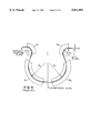
- FIGS. 1A and 1B are electron optical ray diagrams illustrating fundamental parameters of an omega-type energy filter according to the present invention
- FIG. 2 is a graph illustrating regions where every aberration coefficient is less than 1000 and the energy dispersion is in excess of 1 ⁇ m/eV;
- FIG. 3 is a graph in which distance LL of the energy filter own in FIGS. 1A and 1B is plotted against distance L 4 where the sector radius of the magnet M 4 is kept at 50 mm, illustrating values of the sector radius of the magnet M 3 which give low aberrations and great dispersion;
- FIG. 4 is a graph similar to FIG. 3, but other values of the sector radius of the magnet M 3 are used;
- FIG. 5 is a graph illustrating the relations of second-order aberrations and energy dispersion to the sector radius R 3 of the magnet M 3 of the energy filter shown in FIGS. 1A and 1B;
- FIG. 6 is a graph illustrating the relation of energy dispersion to the rectilinear distance 2H between the aperture plane and the slit plane of the energy filter shown in FIGS. 1A and 1B;
- FIG. 7 is a block diagram of an electron microscope having electron optics incorporating an omega-type energy filter according to the invention.
- FIG. 8 is an electron optical ray diagram illustrating the geometry of an A-type omega-type energy filter
- FIG. 9 is an electron optical ray diagram illustrating the geometry of a B-type omega-type energy filter
- FIGS. 10A, 10B, 10C and 10D are graphs illustrating four kinds of electron orbits x ⁇ , y ⁇ , x ⁇ , and y ⁇ of the geometry of FIG. 8;
- FIGS. 11A, 11B, 11C and 11D are graphs illustrating four kinds of electron orbits x ⁇ , y ⁇ , x ⁇ , and y ⁇ of the geometry of FIG. 9.
- FIGS. 1A and 1B there is shown an omega-type energy filter according to the concept of the present invention, illustrating its fundamental parameters.
- FIG. 2 shows regions where every aberration coefficient is less than 1000 and the energy dispersion is in excess of 1 ⁇ it m/eV.
- FIG. 1A shows the configuration from the entrance aperture to the symmetrical plane.
- FIG. 1B shows the configuration from the symmetrical plane to the exit slit.
- the energy filter comprises sector magnets M 1 -M 4 in which the center orbit of a charged-particle beam is deflected at radii of curvature of R 1 -R 4 , respectively.
- the exit face of the sector magnet M 2 and the entrance face of the sector magnet M 3 are tilted at an angle of ⁇ 1 to the center orbit.
- the entrance face of the sector magnet M 2 and the exit face of the sector magnet M 3 are tilted at an angle of ⁇ 2 to the center orbit.
- the exit face of the sector magnet M 1 and the entrance face of the sector magnet M 4 are tilted at an angle of ⁇ 3 to the center orbit.
- the entrance face of the sector magnet M 1 and the exit face of the sector magnet M 4 are tilted at an angle of ⁇ 4 to the centeir orbit.
- L 1 be the distance between the entrance aperture plane and the entrance face of the sector magnet M 1 .
- L 2 be the distance between the exit face of the sector magnet M 1 and the entrance face of the sector magnet M 2 .
- the exit face of the sector magnet M 2 and the entrance face of the sector magnet M 3 are equidistant from the symmetrical plane and separated by a distance of L 3 .
- L 4 be the distance between the exit face of the sector magnet M 3 and the entrance face of the sector magnet M 4 .
- L 5 be the distance between the exit face of the sector magnet M 4 and the exit slit plane.
- the distance between the actual end surface of a magnet and the effective end surface of the magnetic field distribution might be another parameter but this is neglected here.
- the tilt angles of the faces ⁇ 1 , ⁇ 2 , ⁇ 3 , and ⁇ 4 are used to make adjustments for obtaining astigmatic focusing (i.e., the focal point agrees both in x- and y- directions) at image planes and diffraction planes.
- the distances L 3 , L 4 , L 5 , etc. can be used for the adjustments.
- Each face tilt angle ⁇ is normally made to assume a positive value if the charged-particle beam passing across the end surface is converged in the y-direction.
- ⁇ n such as ⁇ 1 , ⁇ 2 , ⁇ 3 , ⁇ 4
- each face tilt angle ⁇ n is selected to be less than 45°.
- the beam is converged in the y-direction where ⁇ 1 , ⁇ 2 , ⁇ 3 , ⁇ 4 >0, as mentioned previously. Consequently, if one face tilt angle is selected to be negative, then the other face tilt angles must be made large. In this case, angles less than 10° are tolerated.
- the allowable angle range is given by
- the omega-type energy filter of the B-type has 10 geometrical aberrations (such as distortions, aperture aberrations, and other aberrations and given by A AAA , A AAG , A AGG , A GGG , B ABB , B ABD , B GBB , B GBD , B ADD , B GDD ) and 8 chromatic aberrations (caused by different energies and given by C AA , C BB , C AG , C BD , C GG , C DD , C GE , C AE ), as described by Ludwig Reimer in "Energy-Filtering Transmission Electron Microscopy", Springer 1995, pp. 43-149; H. Rose, D.
- FIGS. 10A-10D and 11A-11D image planes exist near the entrance face of the sector magnet Ml and near the exit face of the sector magnet M 4 . Since no energy dispersion should take place (achromatic condition) at any image plane, large energy dispersion cannot be expected unless the distance L 5 is large.
- the sector radius R 3 was varied in steps of 5 mm from 50 mm to 85 mm. Regions where the second-order aberrations are less than 1000 and the energy dispersion is in excess of 1 ⁇ m/eV at 200 kV are shown in the graphs, where the image plane-slit plane distance LL is plotted against the distance L 4 . Where the accelerating voltage is n kV, the energy dispersion is in excess of (200/ n) ⁇ m/eV.
- increasing the sector radius R 3 increases the whole size of the filter. Therefore, for optimum design, the sector radius should be reduced to a minimum without sacrificing the performance.
- the sector radius R 3 is greater than 60 mm, the region is interrupted at small values of the distance LL. This occurs where the astigmatic focusing conditions do not hold because the face tilt angle is greater than 45°. Within the indicated range, the astigmatic focusing conditions are met sufficiently.
- the results of FIGS. 3 and 4 are shown together with the energy dispersion. If the sector radius R 3 is increased while maintaining the sector radius R 4 at 50 mm, the energy dispersion increases but the second-order aberrations decrease as a whole. However, only one second-order aberration, or B GBE , does not decrease as the sector radius R 3 is increased. Accordingly, the geometry must be so selected that this aberration becomes 1000, for the following reason.
- the energy dispersion increases with increasing the distance L 4 and with reducing the distance LL as shown in FIGS. 3 and 4. Therefore, the distance L 4 and LL are so determined that the aberration B GBB assumes its critical value.
- a preferable range for the distance L 4 is given by 40 mm ⁇ L 4 ⁇ 70 mm and that a preferable range for the distance LL is given by 55 mm ⁇ LL ⁇ 90 mm.
- FIG. 6 is a graph illustrating the relation of the energy dispersion to the rectilinear distance 2H between the aperture plane and the slit plane of the energy filter shown in FIGS. 1A and 1B.
- the sector radius R 4 two geometries having sector radii of 50 mm and 35 mm, respectively, were built, and they were compared.
- H plotted on the horizontal axis indicates the rectilinear distance from the symmetrical plane of the filter to the slit plane.
- 2H indicates the height of the filter. It can be said that for the same performance, the distance H should be reduced as small as possible.
- Plotted on the vertical axis is the energy dispersion.
- the energy dispersion is so selected that every second-order aberration is less than 1000.
- the performance is improved with reducing the sector radius R 4 .
- the sector radius R 4 is preferably set less than 50 mm.
- the present invention provides an omega-type energy filter in which charged-particles are focused three times in the x-direction, i.e., in a direction perpendicuLar to the magnetic field, and twice in the y-direction, i.e., in the field direction.
- This filter is characterized in that it produces small aberrations and large energy dispersion by satisfying the relations ##EQU8## where L 5 is the distance between the entrance aperture and the entrance face of the sector magnet M 1 and, at the same time, is the distance between the exit face of the sector magnet M 4 and the exit slit.
Abstract
An omega-type energy filter of the B-type in which a beam of charged-particles is focused three times in a direction perpendicular to the direction of magnetic fields and twice in the direction of the magnetic fields. The geometry is so designed that this B-type produces smaller aberrations and larger energy dispersion than the A-type. The filter has four sector magnets M1, M2, M3, and M4 for successively deflecting the charged-particle beam passed through an entrance aperture and for directing the beam toward an exit slit. The entrance aperture and the exit slit are arranged symmetrically with respect to a central, symmetrical plane. The sector magnets M1 and M4 are arranged symmetrically with respect to the symmetrical plane. The sector magnets M2 and M3 are arranged symmetrically with respect to the symmetrical plane. The entrance aperture and the entrance face of the sector magnet M1 are separated by a distance of L5. The exit face of the sector magnet M4 and the exit slit are separated by the same distance of L5. Relations given by ##EQU1## are satisfied.
Description
The present invention relates to an Ω (omega-type) energy filter designed to focus a beam of charged-particles three times in the x-direction normal to the magnetic field direction and two times in the y-direction (i.e., the magnetic field direction).
An electron microscope incorporating an omega-type energy filter is shown in FIG. 7, where an electron gun 11 emits an electron beam. This beam is directed at a specimen 14 via a condenser lens 12 and via an objective lens 13. The electron beam is transmitted through the specimen while modulated by it. Then, the beam reaches a fluorescent plate 20 after passing through an intermediate lens 15, an entrance aperture 16, an omega-type energy filter 17, a slit 18, and a projector lens 19. As a result, a TEM image based on the electrons which have been transmitted through the energy filter and thus have certain energies is formed on the fluorescent screen.
FIGS. 8 and 9 are electron optical ray diagrams of omega-type energy filters. In each of these two figures, four sector magnets and an electron orbit are drawn. In these electron optical ray diagrams, the direction of travel of electrons is taken as the z-direction in a conventional manner. The direction which is perpendicular to the direction of travel of electrons and is located within a plane parallel to the magnetic pole pieces where the electron orbit exists is taken as the x-direction. The direction (the direction of the magnetic field) perpendicular to both x- and z-directions is taken as the y-direction.
As shown in FIGS. 8 and 9, an omega-type energy filter comprises four sector magnets M1, M2, M3, and M4, where the beam shows radii of curvature R1, R2, R3, and R4, respectively. These sector magnets create an omega-shaped electron orbit. Normally, the energy filter is so designed that the incident beam and outgoing beam pass along a common electron optical axis. A symmetrical plane is located midway between the sector magnets M2 and M3 and is perpendicular to the electron optical axis. The entrance aperture and the slit are arranged symmetrically with respect to the symmetrical plane. Also, the magnets M1 and M4 are arranged symmetrically with respect to the symmetrical plane. Furthermore, the magnets M2 and M3 are arranged symmetrically with respect to the symmetrical plane.
FIGS. 10A, 10B, 10C and 10D show four kinds of electron orbits xα, yβ, xγ, and yδ used in the energy filter shown in FIG. 8. In the electron orbit xγ, the height in the x-direction is zero at the position of the entrance aperture (aperture plane). In the electron orbit yδ, the height in the y-direction is zero at the position of the exit slit (slit plane) . In the electron orbit xα, the height in the x-direction is zero at the imaging position (imaging planes) within the filter. In the electron orbit yβ, the height in the y-direction is zero at the imaging position within the filter.
It can be seen from FIG. 10 that in the geometry of FIG. 8, focusing is done three times in the x-direction if the electron orbit xα is employed and three times in the y-direction if the electron orbit yβ is exploited. The geometry of FIG. 8 is normally known as the A-type.
Similarly, in the case of the geometry of FIG. 9, focusing is done three times in the x-direction if the electron orbit xα shown in FIG. 11A is used and twice in the y-direction if the electron orbit yβ is used. The geometry of FIG. 9 is normally known as the B-type.
Where an image is focused onto the fluorescent screen 20, electron microscope diffraction images are formed at the aperture plane and also at the slit plane. The image must be achromatic, but a real achromatic image formed inside the filter is not stigmatic. Only the image which is formed after passing through a round lens placed behind the slit is achromatic and stigmatic image.
The omega-type energy filter is designed so that the beam orbit is symmetrical with respect to the plane located midway between the second magnet M2 and the third magnet M3 as described previously in order that some of the second-order aberrations be reduced down to zero and the other aberrations be reduced. More specifically, let LL be the distance between the final image plane inside the filter and the slit plane. The optics of the filter is so adjusted that the image plane that incident electrons first encounter is at the distance LL from the aperture plane. Under these conditions, the A-type and the B-type differ in the following respects. In the orbit extending in the y-direction (the direction of the magnetic field), the A-type satisfies equations given by yβ=0 and yδ'=0, as shown in FIGS. 10B and 10D, at the symmetrical plane, whereas the B-type meets equations given by yβ'=0 and yδ=0, as shown in FIGS. 11B and 11D, at the symmetrical plane. The prime (') indicates a derivative with respect to Z, i.e., the tilt of the orbit. With respect to the electronic orbit running in the x-direction, both types cater for the relations xα=0 and xγ'=0 at the symmetrical plane.
If these initial conditions are selected, in the A-type, the xγ orbit is focused three times and the yδ orbit is focused three times, as shown in FIG. 10C and 10D. On the other hand, in the B-type, the xγ orbit is focused three times but the yδ orbit is focused only twice, as shown in FIGS. 11C and 11D. Consequently, the image is reversed.
These two types of Ω energy filters have been known for many years but most energy filters developed heretofore are of the A-type, because the B-type suffers from large second-order aberrations, as reported by S. Lanio in "High-resolution imaging magnetic energy filters with simple structure", Optik 73 (1986), pp. 99-107.
However, the B-type has the advantage that the number of convergences in the y-direction is fewer than the A-type by one. Under a uniform magnetic field, electrons undergo a focusing action in a direction vertical to the magnetic field but do not in the direction of the magnetic field. Therefore, the end surface, or face, of the magnet is inclined at an angle to the incident (or outgoing) direction of the beam so as to form a fringe lens. Thus, a focusing action is produced in the y-direction. This focusing action functions like a convex lens in the y-direction and like a concave lens in the x-direction, as can be seen from FIGS. 10A-10D and 11A-11D. Accordingly, in order to focus the electrons three times in the y-direction, the sum of the face tilt angles must be sufficient to focus the electrons three times. Increasing the face tilt angles tends to incur greater aberrations. Also, a concave lens is inevitably produced in the x-direction. Therefore, the uniform field portion must produce a converging action which is strong enough to compensate for the divergence produced by the concave lens. Accordingly, the aforementioned decrease in the number of convergences in the y-direction should essentially increase the number of degrees of freedom in designing the whole system. The conventional concept that the B-type results in greater aberrations is erroneous.
The present invention is intended to solve the foregoing problems. It is an object of the present invention to provide an omega-type energy filter which is based on the B-type omega-type energy filter and appropriately shaped so as to produce smaller aberrations and greater energy dispersion than the A-type omega-type energy filter.
The present invention provides an omega-type energy filter comprising an entrance aperture, four sector magnets M1, M2, M3, and M4, and an exit slit. A charged-particle beam accelerated at U eV is entered from the entrance aperture, deflected by the four sector magnets successively, and directed to the exit slit. The entrance aperture and the exit slit are arranged symmetrically with respect to a center plane located at the center of the filter. Also, the sector magnets M1 and M4 are arranged symmetrically with respect to the center plane. The sector magnets M2 and M3 are arranged symmetrically with respect to the center plane. Electrons are focused three times in the x-direction perpendicular to the magnetic field and twice in the y-direction, or in the direction of the magnetic field. The sector magnet M1 has an entrance face which is spaced from the entrance aperture by a distance of L5. The sector magnet M4 has an exit face which is spaced from the exit slit also by a distance of L5. This filter is characterized in that it satisfies relations given by ##EQU2##
It is assumed that the sector magnets M2 and M3 rotate the beam at a radius of curvature R3 and that the sector magnets M1 and M4 rotate the beam at a radius of curvature R4. In another feature of the invention, the relation R3 >R4 holds.
The first image plane is spaced from the entrance aperture by a distance of LL. An image located immediately ahead of the exit slit is spaced from the exit slit also by a distance of LL. In a further feature of the invention, the following relations are satisfied: ##EQU3##
The sector magnets M2 and M3 facing the symmetrical plane are spaced from the sector magnets M1 and M4, respectively, by a distance of L4. The sector magnets M1 and M4 face the entrance aperture and the exit slit, respectively. In a still other feature of the invention, the following relations are satisfied: ##EQU4##
Other objects and features of the invention will appear in the course of the description thereof, which follows.
FIGS. 1A and 1B are electron optical ray diagrams illustrating fundamental parameters of an omega-type energy filter according to the present invention;
FIG. 2 is a graph illustrating regions where every aberration coefficient is less than 1000 and the energy dispersion is in excess of 1 μm/eV;
FIG. 3 is a graph in which distance LL of the energy filter own in FIGS. 1A and 1B is plotted against distance L4 where the sector radius of the magnet M4 is kept at 50 mm, illustrating values of the sector radius of the magnet M3 which give low aberrations and great dispersion;
FIG. 4 is a graph similar to FIG. 3, but other values of the sector radius of the magnet M3 are used;
FIG. 5 is a graph illustrating the relations of second-order aberrations and energy dispersion to the sector radius R3 of the magnet M3 of the energy filter shown in FIGS. 1A and 1B;
FIG. 6 is a graph illustrating the relation of energy dispersion to the rectilinear distance 2H between the aperture plane and the slit plane of the energy filter shown in FIGS. 1A and 1B;
FIG. 7 is a block diagram of an electron microscope having electron optics incorporating an omega-type energy filter according to the invention;
FIG. 8 is an electron optical ray diagram illustrating the geometry of an A-type omega-type energy filter;
FIG. 9 is an electron optical ray diagram illustrating the geometry of a B-type omega-type energy filter;
FIGS. 10A, 10B, 10C and 10D are graphs illustrating four kinds of electron orbits xα, yβ, xγ, and yδ of the geometry of FIG. 8; and
FIGS. 11A, 11B, 11C and 11D are graphs illustrating four kinds of electron orbits xα, yβ, xγ, and yδ of the geometry of FIG. 9.
Referring to FIGS. 1A and 1B, there is shown an omega-type energy filter according to the concept of the present invention, illustrating its fundamental parameters. FIG. 2 shows regions where every aberration coefficient is less than 1000 and the energy dispersion is in excess of 1 μ it m/eV. FIG. 1A shows the configuration from the entrance aperture to the symmetrical plane. FIG. 1B shows the configuration from the symmetrical plane to the exit slit.
As shown in FIGS 1A and 1B, the energy filter comprises sector magnets M1 -M4 in which the center orbit of a charged-particle beam is deflected at radii of curvature of R1 -R4, respectively. The exit face of the sector magnet M2 and the entrance face of the sector magnet M3 are tilted at an angle of θ1 to the center orbit. The entrance face of the sector magnet M2 and the exit face of the sector magnet M3 are tilted at an angle of θ2 to the center orbit. The exit face of the sector magnet M1 and the entrance face of the sector magnet M4 are tilted at an angle of θ3 to the center orbit. The entrance face of the sector magnet M1 and the exit face of the sector magnet M4 are tilted at an angle of θ4 to the centeir orbit.
Let L1 be the distance between the entrance aperture plane and the entrance face of the sector magnet M1. Let L2 be the distance between the exit face of the sector magnet M1 and the entrance face of the sector magnet M2. The exit face of the sector magnet M2 and the entrance face of the sector magnet M3 are equidistant from the symmetrical plane and separated by a distance of L3. Let L4 be the distance between the exit face of the sector magnet M3 and the entrance face of the sector magnet M4. Let L5 be the distance between the exit face of the sector magnet M4 and the exit slit plane. Let LL be the distance between the entrance aperture plane and the initial image place. The distance between the exit slit plane and the final image plane is set to LL. Because of the symmetry with respect to the symmetrical plane, equations L1 =L5, L2 =L4, R1 =R4, and R2 =R3 hold.
Geometrical factors determining the fundamental optical characteristics of the omega-type energy filter are ten, i.e., the aforementioned radii of curvature R1 (=R4), R2 (=R3), R3, R4, tilt angles of the faces θ1, θ2, θ3, θ4, distances L1 (=L5), L2 (=L4), L3, L4, L5, and LL. The distance between the actual end surface of a magnet and the effective end surface of the magnetic field distribution might be another parameter but this is neglected here. Of these 10 parameters, the tilt angles of the faces θ1, θ2, θ3, and θ4 are used to make adjustments for obtaining astigmatic focusing (i.e., the focal point agrees both in x- and y- directions) at image planes and diffraction planes. Instead, the distances L3, L4, L5, etc. can be used for the adjustments.
Each face tilt angle θ is normally made to assume a positive value if the charged-particle beam passing across the end surface is converged in the y-direction. Empirically, if θn (such as θ1, θ2, θ3, θ4) is >45°, then aberrations are increased greatly or astigmatic focusing does not occur under any condition. Therefore, each face tilt angle θn is selected to be less than 45°. The beam is converged in the y-direction where θ1, θ2, θ3, θ4 >0, as mentioned previously. Consequently, if one face tilt angle is selected to be negative, then the other face tilt angles must be made large. In this case, angles less than 10° are tolerated. Thus, the allowable angle range is given by
-10°<θ.sub.1, θ.sub.2, θ.sub.3, θ.sub.4 <45°
The omega-type energy filter of the B-type has 10 geometrical aberrations (such as distortions, aperture aberrations, and other aberrations and given by AAAA, AAAG, AAGG, AGGG, BABB, BABD, BGBB, BGBD, BADD, BGDD) and 8 chromatic aberrations (caused by different energies and given by CAA, CBB, CAG, CBD, CGG, CDD, CGE, CAE), as described by Ludwig Reimer in "Energy-Filtering Transmission Electron Microscopy", Springer 1995, pp. 43-149; H. Rose, D. Krahl., "Electron Optics of Imaging Energy Filters". Of these aberrations, four aberrations BABD, BGBB, BGDD, and CBD tend to have large values. The accelerating voltage was set to 200 kV. If the values of these four aberrations are less than 1000, and if the energy dispersion λ is in excess of 1 μm/eV (in the case of n kV, it is in excess of 200/ n μm/eV), then the filter conditions are regarded as good. We examined how these conditions varied for about these six parameters.
The most important parameter is the distance L5 (=L1). As can be seen from FIGS. 10A-10D and 11A-11D, image planes exist near the entrance face of the sector magnet Ml and near the exit face of the sector magnet M4. Since no energy dispersion should take place (achromatic condition) at any image plane, large energy dispersion cannot be expected unless the distance L5 is large. In FIG. 2, the distance L4 is plotted on the horizontal axis and the distance LL on the vertical axis. Ranges satisfying the aforementioned conditions are plotted for several values of the distance L5. As described previously, the energy dispersion is increased with increasing the distance L5. It can be observed that the region satisfying the aberration conditions is narrow where L5 =50 mm. Where L5 =40 mm, the right portion of the graph is limited by the aberration BGBB, while the left portion is restricted not by the aberration BGDD as in the case of L5 =45 mm but by energy dispersion 1 μm/eV.
More specifically, conditions giving small aberrations are present over a wide range. However, in many regions, the energy dispersion is no longer less than 1 μm/eV. This tendency becomes extreme where L5 =35 mm, and the range where the energy dispersion is in excess of 1 μm/eV is quite narrow. Therefore, it can be seen from the graph of FIG. 2 that the distance L5 should satisfy the condition
35 mm≦L.sub.5 ≦50 mm
Optimally, 35 mm≦L5 ≦45 mm.
The next most important parameter is the sector radii of the magnets. FIGS. 3 and 4 illustrate values of the sector radius R3 (=R2) of the magnet M3 (M2) which provide low aberrations and great dispersion where the sector radius R4 (=R1) of the magnet M3 (M2) is kept at 50 mm. The sector radius R3 was varied in steps of 5 mm from 50 mm to 85 mm. Regions where the second-order aberrations are less than 1000 and the energy dispersion is in excess of 1 μm/eV at 200 kV are shown in the graphs, where the image plane-slit plane distance LL is plotted against the distance L4. Where the accelerating voltage is n kV, the energy dispersion is in excess of (200/ n) μm/eV.
As can be seen from these graphs, the sector radii R3 (=R2) and R4 (=R1) must satisfy the relation R3 >R4. No usable range exists where R3 =R4. Where R3 is equal to or greater than 65 mm, the energy dispersion is so great that the whole region is limited by the second-order aberrations.
This region is broadened with increasing the sector radius R3 (=R2). Of course, increasing the sector radius R3 increases the whole size of the filter. Therefore, for optimum design, the sector radius should be reduced to a minimum without sacrificing the performance. Where the sector radius R3 is greater than 60 mm, the region is interrupted at small values of the distance LL. This occurs where the astigmatic focusing conditions do not hold because the face tilt angle is greater than 45°. Within the indicated range, the astigmatic focusing conditions are met sufficiently.
FIG. 5 is a graph illustrating the relation of the second-order aberrations and energy dispersion to the sector radius R3 (=R2) of the magnet M3 (M2). The results of FIGS. 3 and 4 are shown together with the energy dispersion. If the sector radius R3 is increased while maintaining the sector radius R4 at 50 mm, the energy dispersion increases but the second-order aberrations decrease as a whole. However, only one second-order aberration, or BGBE, does not decrease as the sector radius R3 is increased. Accordingly, the geometry must be so selected that this aberration becomes 1000, for the following reason. The energy dispersion increases with increasing the distance L4 and with reducing the distance LL as shown in FIGS. 3 and 4. Therefore, the distance L4 and LL are so determined that the aberration BGBB assumes its critical value.
It can be understood from FIGS. 3 and 4 that a preferable range for the distance L4 is given by 40 mm≦L4 ≦70 mm and that a preferable range for the distance LL is given by 55 mm≦LL≦90 mm.
FIG. 6 is a graph illustrating the relation of the energy dispersion to the rectilinear distance 2H between the aperture plane and the slit plane of the energy filter shown in FIGS. 1A and 1B. In order to examine the effect of the sector radius R4, two geometries having sector radii of 50 mm and 35 mm, respectively, were built, and they were compared. H plotted on the horizontal axis indicates the rectilinear distance from the symmetrical plane of the filter to the slit plane. 2H indicates the height of the filter. It can be said that for the same performance, the distance H should be reduced as small as possible. Plotted on the vertical axis is the energy dispersion. As described previously, the energy dispersion is so selected that every second-order aberration is less than 1000. As can be seen from the graph, the performance is improved with reducing the sector radius R4. In practical applications, the sector radius R4 is preferably set less than 50 mm.
It is to be noted that the above-described preferred values of the distance L5, sector radius R4, etc. have been determined under the condition that the accelerating voltage is 200 kV (relativistically modified accelerating voltage U*200 kV) . Where an arbitrary relativistically modified accelerating voltage U* kV is used, it is necessary to correct ##EQU5## For example, in the case of the distance L5, the range should be modified to ##EQU6## Similarly, other lengths are required to be corrected as follows: ##EQU7##
As described thus far, the present invention provides an omega-type energy filter in which charged-particles are focused three times in the x-direction, i.e., in a direction perpendicuLar to the magnetic field, and twice in the y-direction, i.e., in the field direction. This filter is characterized in that it produces small aberrations and large energy dispersion by satisfying the relations ##EQU8## where L5 is the distance between the entrance aperture and the entrance face of the sector magnet M1 and, at the same time, is the distance between the exit face of the sector magnet M4 and the exit slit.
Claims (6)
1. An omega-type energy filter comprising:
an entrance aperture for entering a charged-particle beam accelerated at a relativistically modified accelerating voltage U* kV;
four sector magnets M1, M2, M3, and M4 for successively deflecting said entered charged-particle beam by producing magnetic fields in a y-direction and for directing said charged particle beam toward an exit slit, said entrance aperture and said exit slit being symmetrically arranged with respect to a central, symmetrical plane of said filter, said sector magnets M1 and M4 being symmetrically arranged with respect to said symmetrical plane, said sector magnets M2 and M3 being symmetrically arranged with respect to said symmetrical plane, said charged-particle beam being focused three times in an x-direction perpendicular to the direction of the magnetic fields and twice in the y-direction;
said sector magnets M2 and M3 facing the symmetrical plane are spaced from said sector magnets M1 and M4, respectively, by a distance of L1, said sector magnets M1 and M4 facing said entrance aperture and said exit slit, respectively, and wherein said distance L4 is so selected that relations given by ##EQU9## are satisfied.
2. The omega-type energy filter of claim 1, wherein said sector magnets M2 and M3 have a sector radius of R3 and said sector magnets M1 and M4 have a smaller sector radius of R4 such that R3 >R4.
3. The omega-type energy filter of claim 1, wherein said entrance aperture is spaced from a first image place by a distance of LL and said exit slit is spaced from an image plane located immediately ahead of said exit slit by the same distance of LL, and wherein said distance LL is so selected that relations given by ##EQU10## are satisfied.
4. The omega-type energy filter of claim 1, wherein
said sector magnet M1 having an entrance face which is spaced from said entrance aperture by a distance L5 ;
said sector magnet M4 having an exit face which is spaced from said exit slit by said distance of L5 ; and
said distance L5 being so selected as to satisfy relations given by ##EQU11##
5. The omega-type energy filter of claim 1, wherein said sector magnets M1 and M4 have a sector radius of R4 which satisfies a relation given by ##EQU12##
6. The omega-type energy filter of claim 1, wherein
said sector magnet M2 has an exit face tilted at an angle of θ1 to said charged particle beam,
said sector magnet M3 has an entrance face tilted at an angle of θ1 to said charged particle beam,
said sector magnet M2 has an entrance face tilted at an angle of θ2 to said charged particle beam,
said sector magnet M3 has an exit face tilted at an angle of θ2 to said charred particle beam,
said sector magnet M1 has an exit face tilted at an angle of θ3 to said charged particle beam,
said sector magnet M4 has an entrance face tilted at an angle of θ3 to said charged particle beam,
said sector magnet M1 has an entrance face tilted at an angle of θ4 to said charged particle beam,
said sector magnet M4 has an exit face tilted at an angle of θ4 to said charged particle beam, and
all of these four angles θ1 -θ4 are greater than -10° and less than 45°.
Priority Applications (2)
| Application Number | Priority Date | Filing Date | Title |
|---|---|---|---|
| JP30282996A JP3363718B2 (en) | 1995-11-28 | 1996-11-14 | Omega energy filter |
| US08/757,209 US5811801A (en) | 1995-11-28 | 1996-11-27 | Omega-type energy filter |
Applications Claiming Priority (3)
| Application Number | Priority Date | Filing Date | Title |
|---|---|---|---|
| JP30905095 | 1995-11-28 | ||
| JP30282996A JP3363718B2 (en) | 1995-11-28 | 1996-11-14 | Omega energy filter |
| US08/757,209 US5811801A (en) | 1995-11-28 | 1996-11-27 | Omega-type energy filter |
Publications (1)
| Publication Number | Publication Date |
|---|---|
| US5811801A true US5811801A (en) | 1998-09-22 |
Family
ID=27338566
Family Applications (1)
| Application Number | Title | Priority Date | Filing Date |
|---|---|---|---|
| US08/757,209 Expired - Lifetime US5811801A (en) | 1995-11-28 | 1996-11-27 | Omega-type energy filter |
Country Status (2)
| Country | Link |
|---|---|
| US (1) | US5811801A (en) |
| JP (1) | JP3363718B2 (en) |
Cited By (6)
| Publication number | Priority date | Publication date | Assignee | Title |
|---|---|---|---|---|
| US5952656A (en) * | 1996-12-03 | 1999-09-14 | Jeol Ltd. | Energy filter |
| US5955732A (en) * | 1997-02-27 | 1999-09-21 | Jeol Ltd. | Omega-type energy filter |
| US6097028A (en) * | 1997-02-27 | 2000-08-01 | Jeol Ltd. | Energy filter |
| US6150657A (en) * | 1997-08-28 | 2000-11-21 | Hitachi, Ltd. | Energy filter and electron microscope equipped with the energy filter |
| EP1124251A2 (en) * | 2000-02-08 | 2001-08-16 | LEO Elektronenmikroskopie GmbH | Electron energy filter with magnetic deflection unit |
| US20080237463A1 (en) * | 2003-01-08 | 2008-10-02 | Yoichi Ose | Monochromator and scanning electron microscope using the same |
Citations (5)
| Publication number | Priority date | Publication date | Assignee | Title |
|---|---|---|---|---|
| US4740704A (en) * | 1985-09-13 | 1988-04-26 | Carl-Zeiss-Stiftung | Omega-type electron energy filter |
| US5126565A (en) * | 1990-08-08 | 1992-06-30 | U.S. Philips Corp. | Energy filter for charged particle beam apparatus |
| US5177361A (en) * | 1990-12-22 | 1993-01-05 | Carl-Zeiss-Stiftung | Electron energy filter |
| US5449914A (en) * | 1993-03-26 | 1995-09-12 | Carl-Zeiss-Stiftung | Imaging electron energy filter |
| US5585630A (en) * | 1994-07-25 | 1996-12-17 | Hitachi, Ltd. | Electron energy filter and transmission electron microscope provided with the same |
Family Cites Families (1)
| Publication number | Priority date | Publication date | Assignee | Title |
|---|---|---|---|---|
| JPH07282773A (en) * | 1994-04-07 | 1995-10-27 | Jeol Ltd | Omega-shaped energy filter |
-
1996
- 1996-11-14 JP JP30282996A patent/JP3363718B2/en not_active Expired - Fee Related
- 1996-11-27 US US08/757,209 patent/US5811801A/en not_active Expired - Lifetime
Patent Citations (5)
| Publication number | Priority date | Publication date | Assignee | Title |
|---|---|---|---|---|
| US4740704A (en) * | 1985-09-13 | 1988-04-26 | Carl-Zeiss-Stiftung | Omega-type electron energy filter |
| US5126565A (en) * | 1990-08-08 | 1992-06-30 | U.S. Philips Corp. | Energy filter for charged particle beam apparatus |
| US5177361A (en) * | 1990-12-22 | 1993-01-05 | Carl-Zeiss-Stiftung | Electron energy filter |
| US5449914A (en) * | 1993-03-26 | 1995-09-12 | Carl-Zeiss-Stiftung | Imaging electron energy filter |
| US5585630A (en) * | 1994-07-25 | 1996-12-17 | Hitachi, Ltd. | Electron energy filter and transmission electron microscope provided with the same |
Non-Patent Citations (2)
| Title |
|---|
| "High-Resolution imaging magnetic energy filters with simple structure", S. Lanio, Optik 73, No. 3 (1986), pp. 99-107. |
| High Resolution imaging magnetic energy filters with simple structure , S. Lanio, Optik 73, No. 3 (1986), pp. 99 107. * |
Cited By (9)
| Publication number | Priority date | Publication date | Assignee | Title |
|---|---|---|---|---|
| US5952656A (en) * | 1996-12-03 | 1999-09-14 | Jeol Ltd. | Energy filter |
| US5955732A (en) * | 1997-02-27 | 1999-09-21 | Jeol Ltd. | Omega-type energy filter |
| US6097028A (en) * | 1997-02-27 | 2000-08-01 | Jeol Ltd. | Energy filter |
| US6150657A (en) * | 1997-08-28 | 2000-11-21 | Hitachi, Ltd. | Energy filter and electron microscope equipped with the energy filter |
| EP1124251A2 (en) * | 2000-02-08 | 2001-08-16 | LEO Elektronenmikroskopie GmbH | Electron energy filter with magnetic deflection unit |
| US6559445B2 (en) * | 2000-02-08 | 2003-05-06 | Harald Rose | Electron energy filter with magnetic deflecting regions |
| EP1124251A3 (en) * | 2000-02-08 | 2006-02-01 | LEO Elektronenmikroskopie GmbH | Electron energy filter with magnetic deflection unit |
| US20080237463A1 (en) * | 2003-01-08 | 2008-10-02 | Yoichi Ose | Monochromator and scanning electron microscope using the same |
| US7838827B2 (en) * | 2003-01-08 | 2010-11-23 | Hitachi High-Technologies Corporation | Monochromator and scanning electron microscope using the same |
Also Published As
| Publication number | Publication date |
|---|---|
| JP3363718B2 (en) | 2003-01-08 |
| JPH09213263A (en) | 1997-08-15 |
Similar Documents
| Publication | Publication Date | Title |
|---|---|---|
| US6191423B1 (en) | Correction device for correcting the spherical aberration in particle-optical apparatus | |
| EP1381073B1 (en) | Aberration-corrected charged-particle optical apparatus | |
| US8178850B2 (en) | Chromatic aberration corrector for charged-particle beam system and correction method therefor | |
| JP3269575B2 (en) | Imaging system for charged particle beam with mirror corrector | |
| US7723683B2 (en) | Aberration correction system | |
| US20070069150A1 (en) | Charged particle beam energy width reduction system for charged particle beam system | |
| US6489621B1 (en) | Particle beam system with a device for reducing the energy width of a particle beam | |
| US6960763B2 (en) | Energy filter and electron microscope | |
| US6844548B2 (en) | Wien filter and electron microscope using same | |
| US5811801A (en) | Omega-type energy filter | |
| US10546714B2 (en) | Energy filter and charged particle beam system | |
| US6097028A (en) | Energy filter | |
| US6307205B1 (en) | Omega energy filter | |
| US8373121B2 (en) | Magnetic achromatic mass spectrometer with double focusing | |
| US6797962B1 (en) | Electrostatic corrector for eliminating the chromatic aberration of particle lenses | |
| JP4343951B2 (en) | Single stage charged particle beam energy width reduction system for charged particle beam system | |
| EP1780762B1 (en) | Magnetic energy filter | |
| US20120074315A1 (en) | High resolution energy-selecting electron beam apparatus | |
| US5955732A (en) | Omega-type energy filter | |
| EP3731255B1 (en) | Energy filter and charged particle beam apparatus | |
| JPH04289653A (en) | Mass analyzer of high-transmissivity non-astigmatism | |
| JPS61294746A (en) | Scanning type electron microscope |
Legal Events
| Date | Code | Title | Description |
|---|---|---|---|
| AS | Assignment |
Owner name: JEOL LTD., JAPAN Free format text: ASSIGNMENT OF ASSIGNORS INTEREST;ASSIGNOR:TSUNO, KATSUSHIGE;REEL/FRAME:008934/0021 Effective date: 19971112 |
|
| STCF | Information on status: patent grant |
Free format text: PATENTED CASE |
|
| FEPP | Fee payment procedure |
Free format text: PAYOR NUMBER ASSIGNED (ORIGINAL EVENT CODE: ASPN); ENTITY STATUS OF PATENT OWNER: LARGE ENTITY |
|
| CC | Certificate of correction | ||
| FPAY | Fee payment |
Year of fee payment: 4 |
|
| FPAY | Fee payment |
Year of fee payment: 8 |
|
| FPAY | Fee payment |
Year of fee payment: 12 |