US5793035A - Apparatus and method for spraying herbicide on weeds in a cotton field - Google Patents
Apparatus and method for spraying herbicide on weeds in a cotton field Download PDFInfo
- Publication number
- US5793035A US5793035A US08/626,857 US62685796A US5793035A US 5793035 A US5793035 A US 5793035A US 62685796 A US62685796 A US 62685796A US 5793035 A US5793035 A US 5793035A
- Authority
- US
- United States
- Prior art keywords
- light
- cotton
- plant
- field
- onto
- Prior art date
- Legal status (The legal status is an assumption and is not a legal conclusion. Google has not performed a legal analysis and makes no representation as to the accuracy of the status listed.)
- Expired - Lifetime
Links
- 241000196324 Embryophyta Species 0.000 title claims abstract description 154
- 230000002363 herbicidal effect Effects 0.000 title claims abstract description 52
- 239000004009 herbicide Substances 0.000 title claims abstract description 52
- 229920000742 Cotton Polymers 0.000 title claims abstract description 40
- 238000000034 method Methods 0.000 title claims description 45
- 238000005507 spraying Methods 0.000 title abstract description 26
- 230000003595 spectral effect Effects 0.000 claims abstract description 75
- 240000002024 Gossypium herbaceum Species 0.000 claims abstract description 46
- 235000004341 Gossypium herbaceum Nutrition 0.000 claims abstract description 46
- 241000219146 Gossypium Species 0.000 claims abstract description 39
- 239000002689 soil Substances 0.000 claims abstract description 27
- 244000038559 crop plants Species 0.000 description 23
- 239000007921 spray Substances 0.000 description 19
- 238000010586 diagram Methods 0.000 description 13
- 230000003071 parasitic effect Effects 0.000 description 13
- 239000000463 material Substances 0.000 description 10
- 239000002420 orchard Substances 0.000 description 9
- 240000007371 Cuscuta campestris Species 0.000 description 8
- 230000005855 radiation Effects 0.000 description 8
- 229930002875 chlorophyll Natural products 0.000 description 7
- 235000019804 chlorophyll Nutrition 0.000 description 7
- ATNHDLDRLWWWCB-AENOIHSZSA-M chlorophyll a Chemical group C1([C@@H](C(=O)OC)C(=O)C2=C3C)=C2N2C3=CC(C(CC)=C3C)=[N+]4C3=CC3=C(C=C)C(C)=C5N3[Mg-2]42[N+]2=C1[C@@H](CCC(=O)OC\C=C(/C)CCC[C@H](C)CCC[C@H](C)CCCC(C)C)[C@H](C)C2=C5 ATNHDLDRLWWWCB-AENOIHSZSA-M 0.000 description 7
- 238000003306 harvesting Methods 0.000 description 6
- 238000013500 data storage Methods 0.000 description 5
- 239000011435 rock Substances 0.000 description 4
- 241000894007 species Species 0.000 description 4
- 239000000126 substance Substances 0.000 description 4
- 239000002028 Biomass Substances 0.000 description 3
- 240000003768 Solanum lycopersicum Species 0.000 description 2
- 208000014347 autosomal dominant hyaline body myopathy Diseases 0.000 description 2
- 238000001514 detection method Methods 0.000 description 2
- 230000007613 environmental effect Effects 0.000 description 2
- 239000002184 metal Substances 0.000 description 2
- JITOKQVGRJSHHA-UHFFFAOYSA-M monosodium methyl arsenate Chemical compound [Na+].C[As](O)([O-])=O JITOKQVGRJSHHA-UHFFFAOYSA-M 0.000 description 2
- 230000003287 optical effect Effects 0.000 description 2
- 239000000575 pesticide Substances 0.000 description 2
- 230000002441 reversible effect Effects 0.000 description 2
- 238000001228 spectrum Methods 0.000 description 2
- 244000020518 Carthamus tinctorius Species 0.000 description 1
- 235000013175 Crataegus laevigata Nutrition 0.000 description 1
- 244000075634 Cyperus rotundus Species 0.000 description 1
- 244000068988 Glycine max Species 0.000 description 1
- 235000010469 Glycine max Nutrition 0.000 description 1
- 241001237160 Kallima inachus Species 0.000 description 1
- 235000007688 Lycopersicon esculentum Nutrition 0.000 description 1
- 240000004658 Medicago sativa Species 0.000 description 1
- 244000236458 Panicum colonum Species 0.000 description 1
- 235000015225 Panicum colonum Nutrition 0.000 description 1
- 240000004928 Paspalum scrobiculatum Species 0.000 description 1
- 235000003675 Paspalum scrobiculatum Nutrition 0.000 description 1
- 241000364051 Pima Species 0.000 description 1
- XUIMIQQOPSSXEZ-UHFFFAOYSA-N Silicon Chemical compound [Si] XUIMIQQOPSSXEZ-UHFFFAOYSA-N 0.000 description 1
- 241000607479 Yersinia pestis Species 0.000 description 1
- 240000008042 Zea mays Species 0.000 description 1
- 235000005824 Zea mays ssp. parviglumis Nutrition 0.000 description 1
- 235000002017 Zea mays subsp mays Nutrition 0.000 description 1
- 238000010521 absorption reaction Methods 0.000 description 1
- 230000006978 adaptation Effects 0.000 description 1
- 235000013339 cereals Nutrition 0.000 description 1
- 230000006835 compression Effects 0.000 description 1
- 238000007906 compression Methods 0.000 description 1
- 235000005822 corn Nutrition 0.000 description 1
- 230000000694 effects Effects 0.000 description 1
- 230000005670 electromagnetic radiation Effects 0.000 description 1
- 238000005516 engineering process Methods 0.000 description 1
- 230000003628 erosive effect Effects 0.000 description 1
- 238000009313 farming Methods 0.000 description 1
- 239000012530 fluid Substances 0.000 description 1
- 239000012634 fragment Substances 0.000 description 1
- 238000003384 imaging method Methods 0.000 description 1
- 230000002452 interceptive effect Effects 0.000 description 1
- 230000002147 killing effect Effects 0.000 description 1
- 238000013507 mapping Methods 0.000 description 1
- 238000012986 modification Methods 0.000 description 1
- 230000004048 modification Effects 0.000 description 1
- 238000010899 nucleation Methods 0.000 description 1
- 235000015097 nutrients Nutrition 0.000 description 1
- 239000011368 organic material Substances 0.000 description 1
- 239000002245 particle Substances 0.000 description 1
- 230000008635 plant growth Effects 0.000 description 1
- 230000002829 reductive effect Effects 0.000 description 1
- 229910052710 silicon Inorganic materials 0.000 description 1
- 239000010703 silicon Substances 0.000 description 1
- 238000005549 size reduction Methods 0.000 description 1
- 238000003860 storage Methods 0.000 description 1
- 238000001429 visible spectrum Methods 0.000 description 1
- 239000002699 waste material Substances 0.000 description 1
- XLYOFNOQVPJJNP-UHFFFAOYSA-N water Substances O XLYOFNOQVPJJNP-UHFFFAOYSA-N 0.000 description 1
- 238000009333 weeding Methods 0.000 description 1
Images
Classifications
-
- A—HUMAN NECESSITIES
- A01—AGRICULTURE; FORESTRY; ANIMAL HUSBANDRY; HUNTING; TRAPPING; FISHING
- A01M—CATCHING, TRAPPING OR SCARING OF ANIMALS; APPARATUS FOR THE DESTRUCTION OF NOXIOUS ANIMALS OR NOXIOUS PLANTS
- A01M21/00—Apparatus for the destruction of unwanted vegetation, e.g. weeds
-
- A—HUMAN NECESSITIES
- A01—AGRICULTURE; FORESTRY; ANIMAL HUSBANDRY; HUNTING; TRAPPING; FISHING
- A01M—CATCHING, TRAPPING OR SCARING OF ANIMALS; APPARATUS FOR THE DESTRUCTION OF NOXIOUS ANIMALS OR NOXIOUS PLANTS
- A01M7/00—Special adaptations or arrangements of liquid-spraying apparatus for purposes covered by this subclass
- A01M7/0089—Regulating or controlling systems
-
- G—PHYSICS
- G01—MEASURING; TESTING
- G01C—MEASURING DISTANCES, LEVELS OR BEARINGS; SURVEYING; NAVIGATION; GYROSCOPIC INSTRUMENTS; PHOTOGRAMMETRY OR VIDEOGRAMMETRY
- G01C3/00—Measuring distances in line of sight; Optical rangefinders
- G01C3/02—Details
- G01C3/06—Use of electric means to obtain final indication
- G01C3/08—Use of electric radiation detectors
- G01C3/085—Use of electric radiation detectors with electronic parallax measurement
-
- G—PHYSICS
- G01—MEASURING; TESTING
- G01J—MEASUREMENT OF INTENSITY, VELOCITY, SPECTRAL CONTENT, POLARISATION, PHASE OR PULSE CHARACTERISTICS OF INFRARED, VISIBLE OR ULTRAVIOLET LIGHT; COLORIMETRY; RADIATION PYROMETRY
- G01J1/00—Photometry, e.g. photographic exposure meter
- G01J1/02—Details
- G01J1/04—Optical or mechanical part supplementary adjustable parts
- G01J1/0407—Optical elements not provided otherwise, e.g. manifolds, windows, holograms, gratings
- G01J1/0422—Optical elements not provided otherwise, e.g. manifolds, windows, holograms, gratings using light concentrators, collectors or condensers
-
- G—PHYSICS
- G01—MEASURING; TESTING
- G01J—MEASUREMENT OF INTENSITY, VELOCITY, SPECTRAL CONTENT, POLARISATION, PHASE OR PULSE CHARACTERISTICS OF INFRARED, VISIBLE OR ULTRAVIOLET LIGHT; COLORIMETRY; RADIATION PYROMETRY
- G01J1/00—Photometry, e.g. photographic exposure meter
- G01J1/02—Details
- G01J1/04—Optical or mechanical part supplementary adjustable parts
- G01J1/0407—Optical elements not provided otherwise, e.g. manifolds, windows, holograms, gratings
- G01J1/0437—Optical elements not provided otherwise, e.g. manifolds, windows, holograms, gratings using masks, aperture plates, spatial light modulators, spatial filters, e.g. reflective filters
-
- G—PHYSICS
- G01—MEASURING; TESTING
- G01J—MEASUREMENT OF INTENSITY, VELOCITY, SPECTRAL CONTENT, POLARISATION, PHASE OR PULSE CHARACTERISTICS OF INFRARED, VISIBLE OR ULTRAVIOLET LIGHT; COLORIMETRY; RADIATION PYROMETRY
- G01J1/00—Photometry, e.g. photographic exposure meter
- G01J1/42—Photometry, e.g. photographic exposure meter using electric radiation detectors
- G01J1/44—Electric circuits
-
- G—PHYSICS
- G01—MEASURING; TESTING
- G01J—MEASUREMENT OF INTENSITY, VELOCITY, SPECTRAL CONTENT, POLARISATION, PHASE OR PULSE CHARACTERISTICS OF INFRARED, VISIBLE OR ULTRAVIOLET LIGHT; COLORIMETRY; RADIATION PYROMETRY
- G01J3/00—Spectrometry; Spectrophotometry; Monochromators; Measuring colours
- G01J3/28—Investigating the spectrum
- G01J3/42—Absorption spectrometry; Double beam spectrometry; Flicker spectrometry; Reflection spectrometry
-
- G—PHYSICS
- G01—MEASURING; TESTING
- G01J—MEASUREMENT OF INTENSITY, VELOCITY, SPECTRAL CONTENT, POLARISATION, PHASE OR PULSE CHARACTERISTICS OF INFRARED, VISIBLE OR ULTRAVIOLET LIGHT; COLORIMETRY; RADIATION PYROMETRY
- G01J3/00—Spectrometry; Spectrophotometry; Monochromators; Measuring colours
- G01J3/46—Measurement of colour; Colour measuring devices, e.g. colorimeters
- G01J3/50—Measurement of colour; Colour measuring devices, e.g. colorimeters using electric radiation detectors
- G01J3/501—Colorimeters using spectrally-selective light sources, e.g. LEDs
-
- G—PHYSICS
- G01—MEASURING; TESTING
- G01N—INVESTIGATING OR ANALYSING MATERIALS BY DETERMINING THEIR CHEMICAL OR PHYSICAL PROPERTIES
- G01N21/00—Investigating or analysing materials by the use of optical means, i.e. using sub-millimetre waves, infrared, visible or ultraviolet light
- G01N21/17—Systems in which incident light is modified in accordance with the properties of the material investigated
- G01N21/25—Colour; Spectral properties, i.e. comparison of effect of material on the light at two or more different wavelengths or wavelength bands
- G01N21/255—Details, e.g. use of specially adapted sources, lighting or optical systems
-
- G—PHYSICS
- G01—MEASURING; TESTING
- G01J—MEASUREMENT OF INTENSITY, VELOCITY, SPECTRAL CONTENT, POLARISATION, PHASE OR PULSE CHARACTERISTICS OF INFRARED, VISIBLE OR ULTRAVIOLET LIGHT; COLORIMETRY; RADIATION PYROMETRY
- G01J1/00—Photometry, e.g. photographic exposure meter
- G01J1/42—Photometry, e.g. photographic exposure meter using electric radiation detectors
- G01J2001/4242—Modulated light, e.g. for synchronizing source and detector circuit
-
- G—PHYSICS
- G01—MEASURING; TESTING
- G01N—INVESTIGATING OR ANALYSING MATERIALS BY DETERMINING THEIR CHEMICAL OR PHYSICAL PROPERTIES
- G01N21/00—Investigating or analysing materials by the use of optical means, i.e. using sub-millimetre waves, infrared, visible or ultraviolet light
- G01N21/84—Systems specially adapted for particular applications
- G01N2021/8466—Investigation of vegetal material, e.g. leaves, plants, fruits
Definitions
- the present invention relates to the optical detection of objects. More particularly, the present invention relates to applying herbicide onto weeds in a field of cotton.
- U.S. Pat. No. 5,296,702 discloses structures and methods for differentiating living plants from soil.
- Living plants have a spectral reflectance characteristic in regions of the electromagnetic spectrum which differs from the spectral reflectance characteristic of soil.
- By transmitting light of a first wavelength and light of a second wavelength onto an object and detecting the relative magnitudes of the reflected light of the two wavelengths it can be determined whether the object has the spectral reflectance characteristic of a living plant or the spectral characteristic of soil.
- To conserve herbicide in agricultural spraying operations living plants so differentiated from soil are sprayed with herbicide and the bare ground (which does not have the spectral characteristic of a living plant) is not sprayed.
- Cotton plants are, however, living plants. A device is therefore desired which will spray herbicide onto weeds growing between and around the cotton plants without killing the cotton plants themselves.
- FIG. 1 illustrates a proximity determining sensor
- FIGS. 2A-2C are cross-sectional views of a light detector of the sensor of FIG. 1.
- FIGS. 3A-3E are plan views of a light detector illustrating an operation of the sensor of FIG. 1.
- FIGS. 4A and 4B are views of an operation of the sensor of FIG. 1.
- FIG. 5 is circuit diagram showing one embodiment of a circuit of the sensor of FIG. 1 which generates a signal indicative of a distance to an object.
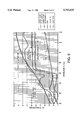
- FIG. 6 is a diagram illustrating different spectral reflection characteristics of a living plant, a dead leaf, soil, and a parasitic weed over a wavelength range of 400-1100 nm.
- FIGS. 7A-7D are diagrams illustrating a light pipe in accordance with some embodiments.
- FIGS. 8A and 8B are diagrams illustrating the spraying of herbicide around the base of a tree.
- FIGS. 9A and 9B are diagrams illustrating a determination of the locations of rows of crop plants.
- FIG. 9C is a diagram illustrating guidance of an implement such as a cultivator through a field of row crop plants using a hydraulic actuator.
- FIG. 10 is a diagram illustrating how weeds growing in the rows of cotton plants are detected and sprayed without spraying the cotton plants.
- FIGS. 11A and 11B illustrate a method and apparatus for spraying herbicide onto weeds in a cotton field without spraying the stalks of the growing cotton plants.
- FIG. 1 illustrates a proximity determining sensor 1.
- Proximity determining sensor 1 comprises a source of light 2 which generates light 3, a light beam forming lens 4 which forms light 3 into a light beam 5, a detector lens 6, and a light detector 7.
- Light beam 5 is aligned in direction A.
- Detector lens 6 has an optic axis in direction B. If, for example, light from light beam 5 reflects off an object located at point P1, then reflected light from the light beam will be incident on light detector 7 at a near image position 8. If, on the other hand, light from light beam 5 reflects off an object located at a distant point P5, then reflected light from the light beam 5 will be incident on the light detector 7 at a far image position 9. Reflections of light from light beam 5 at several intermediate positions P2-P4 are also illustrated in FIG. 1.
- Sensor 1 may, for example, be moved in direction C with respect to the surface 10 of the ground in an open field so that light beam 5 is scanned over surface 10.
- the light of light beam 5 is generated by a plurality of light emitting diodes arranged in a row. Only one of the light emitting diodes is illustrated in FIG. 1 because the row of light emitting diodes extends in the direction perpendicular to the plane illustrated.
- Light beam forming lens 4 is a cylindrical lens which has a longitudinal axis which extends in the direction of the row of light emitting diodes.
- Light beam 5 therefore is a relatively thin sheet of light having a first dimension which extends in the direction perpendicular to the illustrated plane and having a second dimension, the direction of travel of the light, which extends in direction A.
- light detector 7 is a silicon PIN photodiode Model No. SL3-2, manufactured by UDT Sensors, Inc., Hawthorne, Calif. Other suitable photodetectors may be used.
- a charge coupled device CCD may be used.
- lens 4 is a cylindrical lens approximately 3 inches long and approximately 1 inch wide having a focal distance of approximately 0.8 inches, available from United States Precision Lens.
- detector lens 6 is a plano-convex lens approximately 1.5 inches in diameter having a focal distance of approximately 1.5 inches available from United States Precision Lens. The angle between directions A and B is about 7.1 degrees, the lateral distance between light source 2 and light detector 7 is about 2.8 inches, and the distance between light detector lens 6 and light detector 7 is about 2.5 inches.
- FIG. 2A is a cross-sectional view of the light detector 7 of FIG. 1 showing near image position 8 and far image position 9 in greater detail.
- the image plane of the detector surface of light detector 7 is slanted with respect to the optic axis of light detector lens 6 in order to maintain focus of the light arriving from the various object positions P1-P5.
- FIG. 3A is a plan view of the detector surface of the light detector 7 of FIG. 1 looking up into light detector 7 in the direction opposite to direction B.
- Light detector 7 has an active area 11 and a chip boundary 12.
- FIGS. 4A and 4B are diagrams illustrating sensor 1 at two points in time when sensor 1 is moved in direction C with respect to the surface 10 of a field.
- FIG. 4A when at a first point in time light from light beam 5 is reflected off a surface of a relatively tall living plant 14A at a distance D1 from sensor 1, an image of the reflected light is formed on light detector 7 at image position 13.
- FIG. 4B when at a second point in time sensor 1 has moved farther in the direction C with respect to the surface 10 of the field, light from light beam 5 is reflected off a surface of a relatively short living plant 14B at a distance D2 from sensor 1. An image of the reflected light is formed on light detector 7 at image position 15.
- the position of the image of the reflected light on light sensor 7 is indicative of the distance of the reflecting object.
- the angle between the detector axis and the light beam axis is set so that light reflected from light beam 5 strikes the center of the light detector 7 for an object located at a predetermined distance from sensor 1. This allows for a large variation in sensor-to-object distance.
- FIG. 2B is a cross-sectional view of one embodiment of light detector 7.
- Light detector 7 actually comprises a plurality of smaller detectors 7A-7E. If the image created by the light reflecting off the relatively tall living plant 14A is formed at image position 13 on detector 7C, then a corresponding signal will be generated on an output terminal of detector 7C. If, on the other hand, the image created by the light reflected off the relatively short living plant 14B is formed at image position 15 on detector 7B, then a corresponding signal will be generated on an output terminal of detector 7B.
- the distance from the sensor 1 to the object 14A, 14B is determined by identifying from which particular detector of detectors 7A-7E the signal emanates.
- FIG. 2C is a cross-section view of another embodiment of light detector 7.
- Light detector 7 comprises a single detector, the near image position 8 being at one end of the detector active area, the far image position 9 being at an opposite end of the detector active area.
- Such a light detector has an additional anode terminal, the relative magnitude of the signals present on the two anode terminals being indicative of the relative position of the image between two ends of the active area of the detector. The distance from the sensor 1 to the object 14A, 14B is therefore determined by comparing the relative magnitudes of the two anode signals due to the reflected image.
- FIG. 5 is a circuit diagram showing one embodiment of a circuit 16 of sensor 1 which generates a signal on terminal 19, the voltage of the signal being indicative of a relative distance between a reflecting object 14A, 14B and sensor 1.
- the specific embodiment illustrated in FIG. 5 comprises a first trans-impedance amplifier 20, a second trans-impedance amplifier 21, a difference amplifier 22, a summing amplifier 23, and a divider 24.
- Anode terminals 25 and 26 of light detector 7 may, for example, correspond with near image position 8 and far image position 9 of a single detector light detector 7, respectively.
- Light detector 7 has a cathode 27 coupled to an LC circuit 27A. Light detector 7 can be reverse biased or can be operated in the photovoltaic mode as shown.
- the LC circuit 27A is provided to discriminate sunlight as explained below.
- the magnitude of an analog voltage generated on the output terminal 19 of divider 24 is proportional to a distance to a reflecting object. This distance information in the form of an analog voltage is converted to a digital representation before being processed in a microcontroller.
- output terminal 19 is coupled to an analog-to-digital converter input pin of a microcontroller (not shown).
- the LC filter circuit 27A is tuned to the modulation frequency and therefore passes energy at the frequency of the modulation signal and attenuates energy at other frequencies. Accordingly, the component of the signal output by light detector 7 which is due to reflections of light beam 5 is distinguished from components of the signal output by light detector 7 which are due to the more slowly varying ambient sunlight.
- a phase difference between the signal output on output terminal 19 of the circuit of FIG. 5 and a modulation signal used to modulate the light 3 emitted from light source 2 is used by a microcontroller to determine whether an illuminated object is a plant.
- the phase of the signal oscillating in LC circuit 27A is determined by the phase of the radiation received. If more radiation modulated with a first phase is received, the signal oscillating in LC circuit 27A will have a phase relatively closer to the first phase whereas if more radiation modulated with a second phase is received, the signal oscillating in the LC circuit 27A will have a phase relatively closer to the second phase. Both distance information and spectral characteristic information are therefore provided by the same circuit of FIG. 5.
- a separate circuit such as is set forth in U.S. patent application Ser. No. 07/920,942 (now U.S. Pat. No. 5,296,702) is provided to determine whether the illuminated object is a plant so that distance information is provided by the circuit of FIG. 5 and spectral characteristic information is provided by a separate circuit.
- a plurality of units such as sensor 1 is aligned in a row such that the row of units senses objects disposed in a narrow illuminated strip and such that each individual unit senses a corresponding section of the strip.
- the light of light beam 5 may diverge somewhat in the direction perpendicular to the plane illustrated in FIG. 1 so that a band of an object illuminated by beam 5 at near position P1 has a relatively short length whereas that same band illuminated by beam 5 at far location P5 has a relatively long length.
- an image mask 28 is disposed between detector lens 6 and light detector 7.
- FIG. 3B illustrates five images 29A-29E corresponding with light of beam 5 reflected from positions P1-P5, respectively.
- FIG. 3C illustrates an image plane mask 28.
- An opening of image plane mask 28 has a first edge 28A which is non-parallel with respect to a second edge 28B opposite the first edge.
- FIG. 3D illustrates the images 29A1-29E1 which are incident upon the detector surface of light detector 7 due to the operation of image plane mask 28.
- Image 29E1 corresponds with the same illuminated object distance on a distant object located at position P5 as does object image 29A1 on a close object located at position P1.
- FIG. 3E illustrates the image incident on the detecting surface of light detector 7 moving back and forth across the detecting surface as a distance between an object illuminated by light beam 5 is moved toward and away from sensor 1.
- light of light beam 5 reflected back into sensor 1 is also analyzed to determine a spectral characteristic of an object from which the light reflected. Depending on the spectral reflectance characteristic detected, a determination can be made as to whether the object is a plant. Accordingly, a sensor in accordance with some embodiments develops information indicative of whether an object illuminated by light beam 5 is a plant in addition to information indicative of a distance between the sensor and the object.
- FIG. 6 is a diagram illustrating how certain living plants, a dead or dying plant, soil, and a parasitic weed reflect light having different wavelengths over the wavelength range of 400-1100 nm.
- Lines 30, 30A, 30B, 30C and 31 of the graph of FIG. 6 indicate spectral characteristics of a living plant of a first species A, a parasitic weed, a living plant of a second species B, a dead or dying plant and soil, respectively.
- light 3 comprises light having a first wavelength and light having a second wavelength.
- the light having a first wavelength is modulated with a first modulation signal whereas the light of the second wavelength is modulated with a second modulation signal.
- the first modulation signal has the same frequency as the second modulation signal but is offset in phase with respect to the second modulation signal.
- a relative magnitude corresponding with corresponding points on line 30 is indicative of a reflection off a plant whereas a relative magnitude corresponding with corresponding points on line 31 is indicative of reflection off soil.
- FIG. 7A shows a light pipe 32 disposed between image mask 28 and light detector 7.
- Light detector 7 comprises a plurality of light detector chips. Due to the inclusion of light pipe 32, light detector lens 6 need not focus on the relatively small detector surface. Rather, a ray of light 133 passes into light pipe 32 as illustrated in FIG. 7B.
- FIG. 7C is a top-down view illustrating a ray of light 134 passing through light detector lens 6, through the opening in image mask 28, into light pipe 32, and onto light detector 7.
- FIG. 7D is a side view illustrating a ray of light 135 passing through light detector lens 6, through the opening in image mask 28, through light pipe 32, and to light detector 7. Due to the tapered shape of the light pipe 32, the light reflected off the object reflects down the light pipe and onto the smaller light detector surface.
- FIGS. 8A and 8B are diagrams illustrating an orchard sprayer 33 for spraying weeds growing in the ground around trees.
- Orchard sprayer 33 comprises four sensors denoted T, A, B and C in FIGS. 8A and 8B.
- Each of the sensors comprises a plurality of light emitting diodes which emits a narrow long light beam.
- the narrow long light beams emitted from sensors A, B and C are directed toward the ground as illustrated in FIG. 8B such that strips of the ground A, B and C are scanned by light beams from sensors A, B and C, respectively, as a means for moving 34 moves the orchard sprayer with respect to the tree 35.
- the light beam emitted from sensor T is, on the other hand, directed in a substantially horizontal direction so as not to illuminate weeds on the ground but so as to be reflected off tree 35 as illustrated in FIG. 8A.
- Each of the three sensors A, B and C is coupled to a corresponding row of electrically-controlled valves, pumps, or injectors (not shown) so that a plant detected by one of the sensors will be sprayed by nozzles controlled by that sensor.
- each of the electronically-controlled valves (such as part number AM2106 available from Angar Scientific) has an associated spray nozzle and therefore forms an electronically-controlled spray nozzle.
- a distance to tree 35 is determined by sensor T as the means for moving 34 moves the orchard sprayer past the tree.
- sensor T detects an object having a spectral reflectance characteristic indicative of a living plant (which in this case would be tree 35) at a distance between distance DT1 and DT2, the spray nozzles of sensor A are disabled so that tree 35 will not be sprayed.
- the spray nozzles coupled to sensors B and C remain enabled so that weeds growing in the ground in strips B and C will be sprayed.
- Sensors B and C only cause objects having a spectral characteristic of a living plant to be sprayed and therefore do not waste herbicide by spraying the bare ground.
- sensors A and B are disabled leaving only sensor C to detect and spray weeds in strip C.
- sensor C only causes objects having a spectral reflectance of a living plant to be sprayed.
- the spray nozzles for the corresponding strips are enabled in reverse order as sensor T detects the distance to tree 35 getting larger, thereby spraying weeds in the ground around tree 35 and not spraying herbicide onto the tree itself.
- sensors T, A, B and C are mounted in a staggered configuration on means for moving 34 in the direction of travel.
- the sensors A, B and C would therefore be disabled and enabled an appropriate amount of time after the tree is detected by sensor T so that weeds in the corresponding strip will be sprayed right up to the edge of the tree without spraying the tree.
- the speed of the means for moving 34 is therefore detected and used to determine when to enable and disable the spray nozzles.
- the weeds are not sprayed when they are detected but rather are sprayed at a later time as explained in U.S. patent application Ser. No. 07/920,942 (now U.S. Pat. No. 5,296,702).
- an orchard sprayer detects a tree and then controls spray nozzles to spray the tree with a chemical material (such as pesticide and other foliar applied materials) so that the chemical material is not wasted in the spaces between trees.
- a distance sensor is able to determine whether or not the reflected light has a spectral characteristic of a living plant, such an orchard sprayer distinguishes non-plant objects from living trees, thereby overcoming the above described problem of spraying barns and people associated with prior art orchard sprayers.
- material flow is switched on and off depending on the total biomass detected in the field of view and the distance to the biomass. Fluid pressure, nozzle configuration, nozzle direction and other parameters of the spraying operation are also automatically adjusted to accommodate the particular size, density and distance to the biomass. This technique is also usable for selectively dispensing herbicide on weeds along roads, highways and railroad tracks.
- Spraying weeds in the middles with herbicide may therefore be considered a more desirable method of eliminating weeds from the middles.
- Two principal difficulties with spraying weeds are cost of the herbicide material and the potential of contaminating the environment with excessive chemicals. Both of these problems are addressed by aspects of the present embodiment.
- FIGS. 9A and 9B show a means for moving 34 (in this case a tractor) outfitted with a plurality of sensors 36 and a plurality of solenoid-operated spray nozzles (not shown).
- the sensors are mounted on a boom such that a strip of the field perpendicular to direction of tractor movement D is illuminated with modulated light.
- Distance information and information on whether an illuminated object has spectral reflectance indicative of crop plant, weed plant or soil is sent to a central digital processor (not shown).
- the central digital processor determines which illuminated objects having special plant characteristics are crop plants in rows 37 and which are randomly scattered weeds 38.
- the central digital processor disables the spray nozzles located over the rows 37 of crops. As a result, only the weeds 38 in the middles are sprayed. The row crops 38 are not sprayed and herbicide is not wasted on the bare ground in the middles.
- rows of crops are located as described above. Rather than spraying the middles with herbicide, however, the crop plant in the rows are sprayed with foliar nutrients, pesticide, selective herbicide or water.
- a vehicle and/or implement In many farming operations, a vehicle and/or implement is guided through rows of crops in a field. In cultivating row crops, for example, the cultivator implement is guided as fast as possible through the rows of crops so that the cultivator tines come as close as possible to the crops plants without damaging the crop itself. Manually guiding the vehicle and/or implement with respect to the rows is a demanding and tedious task. If, for example, the cultivator strays too close to a row, a section of the row of crop plants may be uprooted.
- Various automatic implement and vehicle guidance systems therefore have been developed to guide vehicles and implements with respect to rows of crops. None of these automatic vehicle guidance systems has, however, enjoyed broad market acceptance.
- a furrow is formed between adjacent rows at the time the row crop is planted.
- "Mole balls” are physical weights which are dragged in such a furrow. As the vehicle moves through the field, the weight of mole ball keeps the mole ball in the furrow between rows. If the vehicle or implement strays toward either row, switches or valves are actuated which operate a hydraulic cylinder to adjust the direction of travel of the vehicle or implement.
- Another vehicle guidance technique involves the use of wires or similar mechanical devices which make actual physical contact with the row crop plants.
- the mechanical touching devices are connected to switches which in turn control a hydraulic or other means of redirecting the vehicle or implement.
- Still other vehicle guidance techniques use ultrasonic sonar and/or infrared detectors.
- An infrared method disclosed in U.S. Pat. No. 5,279,068 directs infrared radiation toward plants in two adjacent crop rows. The two magnitudes of the reflected infrared radiation are compared and the vehicle or implement is steered to keep the magnitudes of the two signals balanced thereby keeping the vehicle or implement centered between the two rows.
- This technique is believed to have problems due to weeds in the middle reflecting and giving incorrect data and due to voids in the row of crop plants not reflecting and not providing sufficient data. Accordingly, the above-described techniques exhibit problems when faced with situations involving fields without well contoured furrows, crop plants which are damaged by physical contact with the guidance device, and voids in crop rows where plants have not survived.
- sensors 36 are mounted on the vehicle or implement.
- the sensors may be disposed to illuminate and therefore follow only one row. Alternatively, the sensors may illuminate and follow multiple rows as is illustrated in FIGS. 9A and 9B.
- Each sensor may output three types of information: 1) information indicative of whether there is an object at a suitable range from the sensor in the field of view, 2) information indicating whether an object in range in the field of view has spectral reflectance properties indicative of a plant crop, a weed, or another object, 3) and information indicative of a distance to the object.
- the magnitude of total reflected radiation detected is the information indicating that an object is at a suitable range from the sensor in the field of view.
- a digital processor coupled to the sensor examines the output of each sensor periodically and stores the information in memory. The digital processor, with the aid of software composed for this purpose, compares the current data being gathered from the sensors to the data stored in memory. From the information available, the digital processor makes very accurate predictions on row location based on object sizes, object heights, ground topology and/or plant locations and spectral reflectance properties. Because the crop plants were planted at the same time in an accurate row pattern, they are probably of a somewhat consistent size. The processor is therefore able to determine accurately which plants are crop and which plants are weeds. Knowing which plants are the crop allows the processor to plot a line which represents the centerline of the crop row 37. In some embodiments, this information is put into a format which is accepted by currently available vehicle guidance systems.
- an implement is guided (for example, a cultivator) with respect to rows in a field.
- FIG. 9C is a diagram illustrating a plurality of sensors 36 coupled to a digital processor 90.
- Digital processor 90 comprises a multi-input analog-to-digital converter 90A, microcontroller 90B and memory 90C.
- Digital processor 90 determines the locations of the rows of crop plants 91 and moves the implement 92 to the left or the right via valve drivers 93, valves 94 and hydraulic actuator 95. If, for example, the implement 92 is a cultivator, the digital processor 90 controls the location of the tines of the cultivator to uproot weeds 96 but to leave crop plants 91.
- Vehicle 97 may or may not be guided by the digital processor 90 through the rows of crops in the field. Voids in crop rows where plants have not survived does not cause the guidance system to fail.
- a vehicle guidance system does not use spectral information but rather uses only distance to object information. For example, where dead plants are to be harvested or where a vehicle or implement is to be guided through a recently planted field in which the seeds have not yet germinated, the distance information may be used to map soil contours and to locate furrows and rows accordingly.
- Some parts of a field may have different types of soil, may receive different amounts of runoff, may receive different amounts of direct sunlight, may have different types of pests, and may be subject to other environmental factors which affect plant growth in different ways. If information bearing on these different environmental factors could be easily gathered, such information could be used in determining how and when to till, to fertilize, and to harvest. It could be determined, for example, that certain parts of a field should be planted with one type of crop whereas other parts of the field should be planted with another type of crop.
- information to make a map of a field is gathered automatically when the field is traversed for another purpose such as cultivating.
- Information indicative of whether a strip of a field illuminated with modulated light contains soil, living crop plants, weeds or other objects, and the size of these plants or other objects is supplied by a sensor to a data storage device.
- the same sensor unit is able to determine the amount of organic material in the soil.
- the data storage device records the soil/plant information and distance information on a storage medium.
- a hard disk drive may be used.
- the data storage device also receives position information from a global positioning system (GPS) device so that the detected characteristics of the field are mapped to the corresponding geographical locations in the field.
- GPS global positioning system
- characteristics of the field can be gathered, downloaded from the data storage device, and later analyzed.
- the analysis can be done in real time and application rates adjusted simultaneously. Using this technique, multiple field maps gathered during multiple growing seasons and for different types of crops can be compared and analyzed.
- Cotton is a crop where it is desirable to discriminate between crop plants in rows and weeds between the crop plants in order to selectively eliminate weeds without damaging the crop plants.
- the cotton plant When the cotton plant is less than a few weeks old, its stalk is soft green tissue which is somewhat translucent to near infrared light. The stalk reflects strongly in the infrared portion of the spectrum and it appears to have much the same spectral reflectance as a weed might. It is therefore difficult to discriminate the cotton crop from the weed plants.
- one weeding method is to spray the rows with a continuous band of selective chemical herbicide which can be tolerated by the cotton crop (e.g., MSMA). Another method measures the differences in spectral reflectance, at certain wavelengths, of cotton plants versus that of the weed plants. Certain weed types can be discriminated from cotton plants on the basis of a different spectral reflectance and treated accordingly.
- FIG. 10 shows a first sensor 39 located on one side of a row of cotton stalks 41 and second sensor 40 located on the other side of the row.
- sensor 40 is oriented to receive only light modulated by sensor 39 and sensor 39 is oriented to receive only light modulated by sensor 40.
- Light reflecting off an object surface in the crop row centerline has an angle of reflection in excess of 45 degrees. In the specific embodiment illustrated, the angle of reflection exceeds 90 degrees.
- the weeds 41 typically do not provide a reflecting surface that reflects light from one side of the row to the other, and because the weeds 41 having a different reflective surface profile do provide such a reflecting surface, the sensor does not detect modulated light reflected from cotton stalks but does detect modulated light reflected from weeds 42 in the cotton rows. The weeds 42 can therefore be selectively eliminated without damaging the cotton stalks 41.
- the cotton stalks become woody and cease to be similar in spectral reflectance to weeds.
- the cotton crops can therefore be discriminated from the weeds using the normal spectral reflectance technique described earlier.
- Weeds in cotton can be eliminated using electronically-controlled plant-eliminating devices including automatic hoes and electronically-controlled herbicide applying spray nozzles.
- FIGS. 11A and 11B are diagrams illustrating a method and apparatus whereby weeds 100 which are growing around the bases of cotton stalks 101 are sprayed with herbicide without spraying substantial amounts of herbicide onto the cotton plants themselves.
- the majority of the leaves (not shown) of the cotton plants are disposed above the upper extent of the cotton stalk illustrations.
- plant detecting techniques such as those disclosed in U.S. Pat. No.
- 5,296,702 are employed to transmit light 102 from a unit 103 toward an object 104 in or adjacent a row of cotton plants 105 and to receive in unit 103 a portion of that light which reflects off the object.
- the object can, for example, be a growing weed, a cotton stalk of a growing cotton plant, or bare ground.
- Light 102 is transmitted and received on the same side of the row 105 between row 105 and an adjacent row, row 105A.
- Distance determining techniques set forth in U.S. patent application Ser. No. 08/276,002 (the subject matter of which is incorporated herein by reference) may also be employed.
- light 102 travels toward object 104 in row 105 at an angle 106 in the range of 30 to 60 degrees with respect to a surface 107 of the field.
- the cotton plants in the rows are adequately mature that their stalks are woody and have a spectral characteristic which differs significantly from a spectral characteristic of a typical weed which would be growing in a cotton field.
- the growing weeds are Purple Nutsedge plants.
- the cotton plants are the Pima or Acala varieties of cotton, are at least six weeks old, and are at least eight inches tall. MSMA herbicide is used.
- unit 103 detects the reflected light and determines that the object 104 has the spectral characteristic of a growing weed (see FIG. 11A), then unit 103 causes herbicide to be sprayed onto the object 104. Any suitable technique for spraying herbicide onto a plant in a field can be used. If, on the other hand, unit 103 detects the reflected light and determines that the object 104 has another spectral characteristic (see FIG. 11B), then unit 103 does not cause herbicide to be sprayed onto object 104.
- Spectral characteristics other than the spectral characteristic of the growing weed include the spectral characteristic of woody cotton stalks and the spectral characteristic of soil. Because the majority of the leaves of the cotton plants is disposed above the area illuminated by the light 102 and is outside the area which can be sprayed, the majority of the leaves of the cotton plants is not sprayed with herbicide.
- Unit 103 may comprise one light emitting diode, photodetector and spray nozzle set or may comprise a plurality of such sets arranged in a row. If a single light emitting diode, photodetector and spray nozzle set is used, then the spectral information obtained will be the average of the spectral characteristics of all objects in the field of view of the set.
- the unit may be moved through the cotton field parallel to the row 105 of cotton plants on an implement attached to and/or drawn by a tractor or other suitable vehicle. In some embodiments there is one unit for each row, whereas in other embodiments there are two units for each row, one disposed on each side of the row.
- unit 103 uses an electronically-controlled valve (part number 9X37 manufactured by KIP Incorporated) to control the application of herbicide.
- a magnetized metal filter may be employed to remove particles from the herbicide which might otherwise plug the valve.
- a sensor (as described above) is used to detect the presence of rocks or metal fragments in the flow of crop material in harvesting equipment and to disengage power before damage can result.
- the field-of-view of a sensor capable of determining a spectral reflectance of an object is aligned across the flow of the crop material in the harvesting equipment.
- the background may be a pipe, wall or panel having a particular spectral reflectance, the flow of crop material flowing between the sensor and the background. Crop material flowing through the field of view of the sensor results in a certain spectral signature being detected by the sensor.
- introduction of a rock into the flow of crop material will result in a substantially different spectral characteristic being detected.
- the difference in spectral characteristics is used to detect the rock and to disengage power from the harvesting equipment.
- a parasitic weed is discriminated from a crop plant.
- Line 30A in FIG. 6 shows the spectral reflectance of a parasitic weed known as Dodder versus wavelength.
- Dodder germinates from a seed which may lie dormant in the ground for up to ten years. When about 2 to 3 inches tall, the Dodder plant finds a host (the host could be a safflower plant, a tomato plant, or an alfalfa plant). The young Dodder plant attaches itself to the host, grows up into the host plant, severs its own roots to the soil, and lives parasitically from its host. When mature, the Dodder plant looks much like a ball of orange colored spaghetti.
- spectral reflectance at two wavelengths is measured.
- an ordinary crop plant typically has a larger difference between the reflectance at wavelengths 670 nanometers and the reflectance at 770 nanometers than the parasitic Dodder weed.
- the magnitude of the difference in spectral reflectance at these two characteristic wavelengths is used to discriminate light reflecting from the parasitic weed from light reflecting from the crop plant.
- the parasitic weed is automatically eliminated by selective spraying or selective cultivation. Over a period of years, all parasitic weeds and seeds of parasitic weeds are eliminated from the field.
Abstract
Description
Claims (14)
Priority Applications (6)
Application Number | Priority Date | Filing Date | Title |
---|---|---|---|
US08/626,857 US5793035A (en) | 1992-07-28 | 1996-04-03 | Apparatus and method for spraying herbicide on weeds in a cotton field |
EP97920078A EP0900451A4 (en) | 1996-04-03 | 1997-04-01 | Apparatus and method for spraying herbicide on weeds in a cotton field |
CA002250889A CA2250889A1 (en) | 1996-04-03 | 1997-04-01 | Apparatus and method for spraying herbicide on weeds in a cotton field |
PCT/US1997/005508 WO1997037372A1 (en) | 1996-04-03 | 1997-04-01 | Apparatus and method for spraying herbicide on weeds in a cotton field |
BR9710417A BR9710417A (en) | 1996-04-03 | 1997-04-01 | Method and apparatus for spraying herbicide on herbs in a cotton field |
AU24359/97A AU721058B2 (en) | 1996-04-03 | 1997-04-01 | Apparatus and method for spraying herbicide on weeds in a cotton field |
Applications Claiming Priority (4)
Application Number | Priority Date | Filing Date | Title |
---|---|---|---|
US07/920,942 US5296702A (en) | 1992-07-28 | 1992-07-28 | Structure and method for differentiating one object from another object |
US08/149,867 US5389781A (en) | 1992-07-28 | 1993-11-10 | Structure and method usable for differentiating a plant from soil in a field |
US08/276,002 US5585626A (en) | 1992-07-28 | 1994-07-15 | Apparatus and method for determining a distance to an object in a field for the controlled release of chemicals on plants, weeds, trees or soil and/or guidance of farm vehicles |
US08/626,857 US5793035A (en) | 1992-07-28 | 1996-04-03 | Apparatus and method for spraying herbicide on weeds in a cotton field |
Related Parent Applications (1)
Application Number | Title | Priority Date | Filing Date |
---|---|---|---|
US08/276,002 Continuation-In-Part US5585626A (en) | 1992-07-28 | 1994-07-15 | Apparatus and method for determining a distance to an object in a field for the controlled release of chemicals on plants, weeds, trees or soil and/or guidance of farm vehicles |
Publications (1)
Publication Number | Publication Date |
---|---|
US5793035A true US5793035A (en) | 1998-08-11 |
Family
ID=24512163
Family Applications (1)
Application Number | Title | Priority Date | Filing Date |
---|---|---|---|
US08/626,857 Expired - Lifetime US5793035A (en) | 1992-07-28 | 1996-04-03 | Apparatus and method for spraying herbicide on weeds in a cotton field |
Country Status (6)
Country | Link |
---|---|
US (1) | US5793035A (en) |
EP (1) | EP0900451A4 (en) |
AU (1) | AU721058B2 (en) |
BR (1) | BR9710417A (en) |
CA (1) | CA2250889A1 (en) |
WO (1) | WO1997037372A1 (en) |
Cited By (60)
Publication number | Priority date | Publication date | Assignee | Title |
---|---|---|---|---|
US6062496A (en) * | 1996-06-17 | 2000-05-16 | Patchen, Inc. | Valve cartridge having pressure sensor for agriculture and weed control |
US6207956B1 (en) * | 1998-09-04 | 2001-03-27 | The Toro Company | Method and apparatus for quantitative determination of turfgrass color |
US6276617B1 (en) * | 1999-12-30 | 2001-08-21 | Magspray Corporation | Agricultural liquid application nozzle, system, and method |
US6442486B1 (en) * | 1998-09-09 | 2002-08-27 | Satake Corporation | Method for determining amount of fertilizer application for grain crops, method for estimating quality and yield of grains and apparatus for providing grain production information |
US6443365B1 (en) * | 1997-12-08 | 2002-09-03 | Weed Control Australia Pty Ltd. | Discriminating ground vegetation in agriculture |
US6596996B1 (en) | 2001-07-24 | 2003-07-22 | The Board Of Regents For Oklahoma State University | Optical spectral reflectance sensor and controller |
US6601341B2 (en) | 2001-07-24 | 2003-08-05 | The Board Of Regents For Oklahoma State University | Process for in-season fertilizer nitrogen application based on predicted yield potential |
US20040004119A1 (en) * | 2002-05-16 | 2004-01-08 | United Parcel Service Of America, Inc. | Systems and methods for package sortation and delivery using radio frequency identification technology |
US20040034459A1 (en) * | 2000-10-14 | 2004-02-19 | Ingo Hoelscher | System for the application of pesticides |
EP1394530A1 (en) * | 2002-08-27 | 2004-03-03 | Amazonen-Werke H. Dreyer GmbH & Co. KG | Arrangement for the contactless determination of vegetation in a field |
US6702200B2 (en) | 2001-07-24 | 2004-03-09 | The Board Of Regents For Oklahoma State University | Nozzle attitude controller for spot and variable rate application of agricultural chemicals and fertilizers |
WO2004044619A2 (en) * | 2002-11-11 | 2004-05-27 | Qinetiq Limited | Proximity sensor |
US20040149893A1 (en) * | 2001-04-26 | 2004-08-05 | Scott Christopher C | Selective plant discrimination |
US20040227926A1 (en) * | 2003-05-15 | 2004-11-18 | Chieh-Jen Lee | Receiving module |
US20040231239A1 (en) * | 2001-07-24 | 2004-11-25 | The Board Of Regents For Oklahoma State University | Use of within-field-element-size CV for improved nutrient fertilization in crop production |
US20040237394A1 (en) * | 2001-07-24 | 2004-12-02 | Mayfield Ted E. | Low-cost system and method for the precision application of agricultural products |
US20050006469A1 (en) * | 2003-07-10 | 2005-01-13 | United Parcel Service Of America, Inc. | Methods, systems, and computer-readable media for linking object identification data to package identification data |
US20050024213A1 (en) * | 2003-08-01 | 2005-02-03 | David Franzen | Sensor and method of detecting the condition of a turf grass |
US20050072862A1 (en) * | 2001-05-31 | 2005-04-07 | Terra Spase, Inc. | Conduit including sensors for monitoring and maintenance of vegetation |
US20060044546A1 (en) * | 2002-11-11 | 2006-03-02 | Qinetiq Limited | Ranging apparatus |
WO2006021207A1 (en) | 2004-05-10 | 2006-03-02 | Frank Poulsen | System for selective treatment of plants in row |
US20060146560A1 (en) * | 2002-11-11 | 2006-07-06 | Qinetiq Limited | Structured light projector |
WO2006117581A1 (en) * | 2005-04-29 | 2006-11-09 | G & G Növényvédelmi és Kereskedelmi Kft. | Setup for constructing a weed map |
US20070044445A1 (en) * | 2005-08-01 | 2007-03-01 | Pioneer Hi-Bred International, Inc. | Sensor system, method, and computer program product for plant phenotype measurement in agricultural environments |
US20080191054A1 (en) * | 2007-02-09 | 2008-08-14 | Tsd Integrated Controls, Llc | Method and system for applying materials to crops |
US20090247405A1 (en) * | 2008-03-26 | 2009-10-01 | Ricks Phillip E | Method of crop production |
US20100283603A1 (en) * | 2005-06-08 | 2010-11-11 | Massey University | Pasture management |
US20100301990A1 (en) * | 2009-05-29 | 2010-12-02 | Christopher Michael Bourget | Appartus and method for affecting change in a target using an integrated lighting system |
US20110147479A1 (en) * | 2005-07-08 | 2011-06-23 | Dimensions Agri Technologies Ag | System for controlled application of herbicides |
US8189189B1 (en) | 2008-10-08 | 2012-05-29 | Herendeen Robert O | LED sensor for process control |
CN102798616A (en) * | 2011-05-26 | 2012-11-28 | 株式会社拓普康 | Plant sensor |
US20140299749A1 (en) * | 2013-04-04 | 2014-10-09 | Ag Leader Technology | Using An Active Light Sensor to Quantify Plants |
US20150027044A1 (en) * | 2013-03-07 | 2015-01-29 | Blue River Technology, Inc. | System and method for plant treatment |
CN104458596A (en) * | 2014-12-21 | 2015-03-25 | 华东交通大学 | Device and method for spectral detection of content of malondialdehyde in tomato leaves in multi-angle and in-situ manner |
US9066465B2 (en) | 2013-02-20 | 2015-06-30 | Deere & Company | Soil compaction reduction system and method |
US20160029612A1 (en) * | 2014-07-31 | 2016-02-04 | Elwha Llc | Systems and methods for deactivating plant material outside of a growing region |
WO2016026052A1 (en) * | 2014-08-22 | 2016-02-25 | Gary Zhang | Spraying monitoring system |
US9282693B2 (en) | 2013-02-20 | 2016-03-15 | Deere & Company | Data encoding with planting attributes |
US9320196B2 (en) | 2013-02-20 | 2016-04-26 | Deere & Company | Stripper plate adjustment |
USD766399S1 (en) | 2014-10-03 | 2016-09-13 | Deere & Company | Hybrid spray nozzle turret |
US9648864B1 (en) * | 2014-09-12 | 2017-05-16 | Hugh C. Kent | Electrically powered infrared based thermal weed control system |
US9658201B2 (en) | 2013-03-07 | 2017-05-23 | Blue River Technology Inc. | Method for automatic phenotype measurement and selection |
US9668420B2 (en) | 2013-02-20 | 2017-06-06 | Deere & Company | Crop sensing display |
US9717171B2 (en) | 2013-03-07 | 2017-08-01 | Blue River Technology Inc. | System and method for automated odometry calibration for precision agriculture systems |
US9884330B2 (en) | 2014-06-20 | 2018-02-06 | Deere & Company | Broadband spray nozzle systems and methods |
US10010067B2 (en) | 2014-09-12 | 2018-07-03 | Stw, Llc | Electrically powered infrared based thermal weed control system |
US10178828B2 (en) | 2013-02-20 | 2019-01-15 | Deere & Company | Per plant crop sensing resolution |
US10189031B2 (en) | 2014-06-20 | 2019-01-29 | Deere & Company | Hybrid flow nozzle and control system |
CN109329246A (en) * | 2018-10-18 | 2019-02-15 | 华南农业大学 | What a kind of cotton aviation sprayed pre-wets operational method and detection method |
US10269107B2 (en) | 2017-02-23 | 2019-04-23 | Global Neighbor Inc | Selective plant detection and treatment using green luminance photometric machine vision scan with real time chromaticity operations and image parameter floors for low processing load |
US10327393B2 (en) | 2013-03-07 | 2019-06-25 | Blue River Technology Inc. | Modular precision agriculture system |
CN110546452A (en) * | 2017-04-21 | 2019-12-06 | 发茂特有限公司 | Product and method for measuring the surface topography of crops or pastures |
US10773271B2 (en) | 2014-06-20 | 2020-09-15 | Deere & Company | Time varying control of the operation of spray systems |
US11083197B2 (en) * | 2015-12-30 | 2021-08-10 | Investigaciones Biologicas en Agroquimicos Rosario S.A. | Herbicidal composition comprising chromone derivatives and a method for weed control |
US11129343B2 (en) | 2015-03-06 | 2021-09-28 | Blue River Technology Inc. | Modular precision agriculture system |
US11212962B2 (en) | 2013-02-20 | 2022-01-04 | Deere & Company | Field condition determination |
WO2022111880A1 (en) * | 2020-11-26 | 2022-06-02 | Robert Bosch Gmbh | Method and device for classifying plants, and computer program product |
EP4011186A1 (en) * | 2020-11-03 | 2022-06-15 | Deere & Company | Agricultural nutrient application using real-time spectroscopic analysis of live crop |
US20220211025A1 (en) * | 2021-01-06 | 2022-07-07 | Cnh Industrial America Llc | System and method for performing spraying operations with an agricultural sprayer |
US11457621B2 (en) * | 2019-07-12 | 2022-10-04 | Deere & Company | Agricultural sprayer system and method |
Families Citing this family (14)
Publication number | Priority date | Publication date | Assignee | Title |
---|---|---|---|---|
DE19723770A1 (en) * | 1997-06-06 | 1998-12-10 | Hydro Agri Deutschland Gmbh | Plant condition measuring device |
BE1011866A3 (en) * | 1998-04-07 | 2000-02-01 | Teejet Technologies Besloten V | Inspection unit. |
EP1000540A1 (en) * | 1998-11-16 | 2000-05-17 | McLoughlin, Daniel | Image processing |
DE19950396C2 (en) * | 1999-10-12 | 2002-01-31 | Norsk Hydro As | Device and method for determining the condition of plants |
DE10002880C1 (en) * | 2000-01-10 | 2001-06-13 | Norsk Hydro As | Monitor system useful for examining the health of plants and vegetation comprises a vehicle equipped to register active and passive light and fluorescent spectra with satellite GPS links to determine corrective actions to be taken on site |
US7050910B2 (en) | 2003-12-18 | 2006-05-23 | Kemira Growhow Oy | Method and system for analyzing site-specific growth factors limiting production |
DE102006002437A1 (en) * | 2006-01-11 | 2007-07-12 | Agrocom Gmbh & Co. Agrarsysteme Kg | Measuring device for agricultural harvester, has optical sensor system that detects chlorophyll content of cultivated plants during harvesting process, and evaluation unit that generates weed signal |
ATE551597T1 (en) * | 2006-08-01 | 2012-04-15 | Photonic Detection Systems Pty Ltd | OPTICAL PERCEPTION SYSTEM AND METHOD FOR DIFFERENTIATION OF PLANTS |
ES2384947B1 (en) * | 2010-06-21 | 2013-05-20 | Consejo Superior De Investigaciones Cientificas (Csic) | SYSTEM AND METHOD FOR THE APPLICATION OF HERBICIDE. |
DE102017210804A1 (en) * | 2017-06-27 | 2018-12-27 | Robert Bosch Gmbh | Method Apply a spray to a field |
US20200100491A1 (en) * | 2018-09-28 | 2020-04-02 | Vital Vio, Inc. | Inactivation of Insects With Light |
US10656133B2 (en) * | 2018-10-19 | 2020-05-19 | Trimble Inc. | Controlling plant detection systems using phase delay analysis |
DE102018126585A1 (en) | 2018-10-25 | 2020-04-30 | Amazonen-Werke H. Dreyer Gmbh & Co. Kg | Process for applying spray liquid |
DE102020002721A1 (en) | 2020-05-06 | 2021-11-11 | Wolfram Strothmann | Multi-row machine and method for the mechanical regulation of weeds and pests. |
Citations (55)
Publication number | Priority date | Publication date | Assignee | Title |
---|---|---|---|---|
SU203340A1 (en) * | К. К. Полевицкий | AUTOMATIC CREATOR OF CULTURAL PLANTS, EXAMPLE OF SUGAR BEET | ||
GB590598A (en) * | 1943-04-12 | 1947-07-23 | Leo Aloysius Marihart | Agricultural machines for hoeing, weeding or thinning |
US2514405A (en) * | 1948-05-14 | 1950-07-11 | M P H Ind | Photoelectric unit for agricultural operations |
US2682132A (en) * | 1948-05-14 | 1954-06-29 | M P H Ind | Agricultural machine |
US2894178A (en) * | 1956-01-18 | 1959-07-07 | Hewlett Packard Co | Photoelectric system |
US3168238A (en) * | 1962-10-19 | 1965-02-02 | Fmc Corp | Chemical distributing machine |
US3373870A (en) * | 1966-07-08 | 1968-03-19 | American Tobacco Co | Cigar classification apparatus |
US3488511A (en) * | 1966-10-25 | 1970-01-06 | Tokyo Shibaura Electric Co | Automatic identifying apparatus of postage stamp indications |
US3512587A (en) * | 1967-10-09 | 1970-05-19 | Eversman Mfg Co | Photoelectrically controlled plant thinners |
US3590925A (en) * | 1968-05-06 | 1971-07-06 | Tara Corp | Automated agricultural system |
US3609913A (en) * | 1969-07-24 | 1971-10-05 | Int Electric Fence Co Inc | Magnetic memory control |
US3652844A (en) * | 1970-02-09 | 1972-03-28 | Ralph A Scott Jr | Laser plant control |
US3701218A (en) * | 1969-08-07 | 1972-10-31 | Deere & Co | Spray type row crop thinner |
SU382367A1 (en) * | 1971-11-15 | 1973-05-25 | Полтавский ордена Трудового Красного Знамени сельскохоз йственный институт | |
US3821550A (en) * | 1969-07-18 | 1974-06-28 | Deere & Co | Plant thinner having radiant energy plant detecting means |
SU471074A1 (en) * | 1973-06-11 | 1975-05-25 | Полтавский Ордена Трудового Красного Знамени Сельскохозяйственный Институт | The way to recognize plants from soil lumps and stones |
US3910701A (en) * | 1973-07-30 | 1975-10-07 | George R Henderson | Method and apparatus for measuring light reflectance absorption and or transmission |
SU547183A1 (en) * | 1975-02-24 | 1977-02-25 | Кировоградский институт сельскохозяйственного машиностроения | The way to recognize plants on the background of the soil |
US4015366A (en) * | 1975-04-11 | 1977-04-05 | Advanced Decision Handling, Inc. | Highly automated agricultural production system |
US4029391A (en) * | 1974-08-22 | 1977-06-14 | Sterndent Corporation | Light probe and interface therefor |
US4092800A (en) * | 1973-09-24 | 1978-06-06 | Phytox Corporation | Vegetation control |
US4179216A (en) * | 1977-05-31 | 1979-12-18 | Franz Plasser Bahnbaumaschinen-Industriegesellschaft M.B.H. | Apparatus for measuring the profile of a railroad tunnel |
US4206569A (en) * | 1978-09-05 | 1980-06-10 | Randolph Joe G | Weed sprayer |
SU968631A1 (en) * | 1981-04-01 | 1982-10-23 | Всесоюзный Научно-Исследовательский Институт По Испытанию Машин И Оборудования Для Животноводства И Кормопроизводства | Colour sensitive sensor |
US4369886A (en) * | 1979-10-09 | 1983-01-25 | Ag-Electron, Inc. | Reflectance ratio sorting apparatus |
WO1984000211A1 (en) * | 1982-06-29 | 1984-01-19 | Labsystems Oy | Method for the measurement of the difference in colour contents of samples |
US4482960A (en) * | 1981-11-20 | 1984-11-13 | Diffracto Ltd. | Robot tractors |
US4527897A (en) * | 1981-09-18 | 1985-07-09 | Tokyo Shibaura Denki Kabushiki Kaisha | Apparatus for detecting specific color |
US4550526A (en) * | 1984-01-23 | 1985-11-05 | Willard Smucker | Implement for contact application of liquid herbicides to crops |
US4558786A (en) * | 1983-06-15 | 1985-12-17 | Marvin M. Lane | Electro-optical sorter |
US4618257A (en) * | 1984-01-06 | 1986-10-21 | Standard Change-Makers, Inc. | Color-sensitive currency verifier |
US4699273A (en) * | 1983-12-06 | 1987-10-13 | Gunson's Sortex Limited | Sorting machine |
US4709265A (en) * | 1985-10-15 | 1987-11-24 | Advanced Resource Development Corporation | Remote control mobile surveillance system |
SU1377606A1 (en) * | 1985-01-09 | 1988-02-28 | Научно-исследовательский и проектно-технологический институт механизации и электрификации сельского хозяйства Нечерноземной зоны РСФСР | Colour-contrast transducer |
GB2200446A (en) * | 1987-01-27 | 1988-08-03 | So Resprom | Colour sensor for crop identification |
US4768713A (en) * | 1982-12-15 | 1988-09-06 | Roper Bert E | Grove sprayer |
DE3900221A1 (en) * | 1988-01-19 | 1989-07-27 | Fmc Corp | CONTROL SYSTEM FOR EVEN SPRAYING OF PLANTS |
US4989783A (en) * | 1989-08-14 | 1991-02-05 | Fmc Corporation | Sensor mounting |
US4991341A (en) * | 1988-01-19 | 1991-02-12 | Fmc Corporation | Control system for uniform spraying of plants |
US5006719A (en) * | 1988-07-26 | 1991-04-09 | Heidelberger Druckmaschinen Ag | Device for detecting the edge location of an object |
US5015868A (en) * | 1987-11-30 | 1991-05-14 | Goldstar Co., Ltd. | Real time distance sensor |
US5021645A (en) * | 1989-07-11 | 1991-06-04 | Eaton Corporation | Photoelectric color sensor for article sorting |
US5068540A (en) * | 1989-08-04 | 1991-11-26 | Ricoh Company, Ltd. | Distance measuring apparatus having automatic gain control |
US5072128A (en) * | 1989-07-26 | 1991-12-10 | Nikon Corporation | Defect inspecting apparatus using multiple color light to detect defects |
US5109161A (en) * | 1989-10-14 | 1992-04-28 | Canon Kabushiki Kaisha | Light emitter and optical system for a distance measuring device |
US5144767A (en) * | 1988-06-22 | 1992-09-08 | The Minister For Agriculture & Rural Affairs For The State Of New South Wales | Controller for agricultural sprays |
US5222324A (en) * | 1991-02-21 | 1993-06-29 | Neall Donald L O | Crop spraying system |
US5233177A (en) * | 1991-01-18 | 1993-08-03 | The Furukawa Electric Co., Ltd. | Optical sensor with fiberless optical member |
US5237386A (en) * | 1989-03-22 | 1993-08-17 | Kidde-Graviner Limited | Optical coupling arrangement for particulate detector |
US5278423A (en) * | 1992-12-30 | 1994-01-11 | Schwartz Electro-Optics, Inc. | Object sensor and method for use in controlling an agricultural sprayer |
US5296702A (en) * | 1992-07-28 | 1994-03-22 | Patchen California | Structure and method for differentiating one object from another object |
US5319196A (en) * | 1992-12-07 | 1994-06-07 | Magnavox Electronic Systems Company | Optical rotation sensor |
US5347122A (en) * | 1989-12-08 | 1994-09-13 | Cambridge Imaging Limited | Light transmission system with photon transfer to an optical detector and cell investigation techniques using the light transmission system |
US5386285A (en) * | 1992-02-28 | 1995-01-31 | Mitsubishi Denki Kabushiki Kaisha | Obstacle detecting device for a vehicle |
US5585626A (en) * | 1992-07-28 | 1996-12-17 | Patchen, Inc. | Apparatus and method for determining a distance to an object in a field for the controlled release of chemicals on plants, weeds, trees or soil and/or guidance of farm vehicles |
Family Cites Families (3)
Publication number | Priority date | Publication date | Assignee | Title |
---|---|---|---|---|
JP3359702B2 (en) * | 1993-06-28 | 2002-12-24 | 株式会社前川製作所 | Heterogeneous plant detection method and weed control method using the detection method |
DE4329343A1 (en) * | 1993-08-27 | 1995-03-09 | Schering Ag | Image-analytical method, suitable for use in the field, for the automatic detection and combatting of types of weed |
DE4413739C2 (en) * | 1994-04-20 | 1996-07-18 | Deutsche Forsch Luft Raumfahrt | Establishment for recognizing and differentiating plants and soil areas as well as for distinguishing crops and wild plants |
-
1996
- 1996-04-03 US US08/626,857 patent/US5793035A/en not_active Expired - Lifetime
-
1997
- 1997-04-01 CA CA002250889A patent/CA2250889A1/en not_active Abandoned
- 1997-04-01 BR BR9710417A patent/BR9710417A/en not_active IP Right Cessation
- 1997-04-01 EP EP97920078A patent/EP0900451A4/en not_active Withdrawn
- 1997-04-01 WO PCT/US1997/005508 patent/WO1997037372A1/en not_active Application Discontinuation
- 1997-04-01 AU AU24359/97A patent/AU721058B2/en not_active Expired
Patent Citations (57)
Publication number | Priority date | Publication date | Assignee | Title |
---|---|---|---|---|
SU203340A1 (en) * | К. К. Полевицкий | AUTOMATIC CREATOR OF CULTURAL PLANTS, EXAMPLE OF SUGAR BEET | ||
GB590598A (en) * | 1943-04-12 | 1947-07-23 | Leo Aloysius Marihart | Agricultural machines for hoeing, weeding or thinning |
US2514405A (en) * | 1948-05-14 | 1950-07-11 | M P H Ind | Photoelectric unit for agricultural operations |
US2682132A (en) * | 1948-05-14 | 1954-06-29 | M P H Ind | Agricultural machine |
US2894178A (en) * | 1956-01-18 | 1959-07-07 | Hewlett Packard Co | Photoelectric system |
US3168238A (en) * | 1962-10-19 | 1965-02-02 | Fmc Corp | Chemical distributing machine |
US3373870A (en) * | 1966-07-08 | 1968-03-19 | American Tobacco Co | Cigar classification apparatus |
US3488511A (en) * | 1966-10-25 | 1970-01-06 | Tokyo Shibaura Electric Co | Automatic identifying apparatus of postage stamp indications |
US3512587A (en) * | 1967-10-09 | 1970-05-19 | Eversman Mfg Co | Photoelectrically controlled plant thinners |
US3590925A (en) * | 1968-05-06 | 1971-07-06 | Tara Corp | Automated agricultural system |
US3821550A (en) * | 1969-07-18 | 1974-06-28 | Deere & Co | Plant thinner having radiant energy plant detecting means |
US3609913A (en) * | 1969-07-24 | 1971-10-05 | Int Electric Fence Co Inc | Magnetic memory control |
US3701218A (en) * | 1969-08-07 | 1972-10-31 | Deere & Co | Spray type row crop thinner |
US3652844A (en) * | 1970-02-09 | 1972-03-28 | Ralph A Scott Jr | Laser plant control |
SU382367A1 (en) * | 1971-11-15 | 1973-05-25 | Полтавский ордена Трудового Красного Знамени сельскохоз йственный институт | |
SU471074A1 (en) * | 1973-06-11 | 1975-05-25 | Полтавский Ордена Трудового Красного Знамени Сельскохозяйственный Институт | The way to recognize plants from soil lumps and stones |
US3910701A (en) * | 1973-07-30 | 1975-10-07 | George R Henderson | Method and apparatus for measuring light reflectance absorption and or transmission |
US4092800A (en) * | 1973-09-24 | 1978-06-06 | Phytox Corporation | Vegetation control |
US4029391A (en) * | 1974-08-22 | 1977-06-14 | Sterndent Corporation | Light probe and interface therefor |
SU547183A1 (en) * | 1975-02-24 | 1977-02-25 | Кировоградский институт сельскохозяйственного машиностроения | The way to recognize plants on the background of the soil |
US4015366A (en) * | 1975-04-11 | 1977-04-05 | Advanced Decision Handling, Inc. | Highly automated agricultural production system |
US4179216A (en) * | 1977-05-31 | 1979-12-18 | Franz Plasser Bahnbaumaschinen-Industriegesellschaft M.B.H. | Apparatus for measuring the profile of a railroad tunnel |
US4206569A (en) * | 1978-09-05 | 1980-06-10 | Randolph Joe G | Weed sprayer |
US4369886A (en) * | 1979-10-09 | 1983-01-25 | Ag-Electron, Inc. | Reflectance ratio sorting apparatus |
SU968631A1 (en) * | 1981-04-01 | 1982-10-23 | Всесоюзный Научно-Исследовательский Институт По Испытанию Машин И Оборудования Для Животноводства И Кормопроизводства | Colour sensitive sensor |
US4527897A (en) * | 1981-09-18 | 1985-07-09 | Tokyo Shibaura Denki Kabushiki Kaisha | Apparatus for detecting specific color |
US4482960A (en) * | 1981-11-20 | 1984-11-13 | Diffracto Ltd. | Robot tractors |
WO1984000211A1 (en) * | 1982-06-29 | 1984-01-19 | Labsystems Oy | Method for the measurement of the difference in colour contents of samples |
US4768713B1 (en) * | 1982-12-15 | 1995-03-21 | Bert E Roper | Grove sprayer |
US4768713A (en) * | 1982-12-15 | 1988-09-06 | Roper Bert E | Grove sprayer |
US4558786A (en) * | 1983-06-15 | 1985-12-17 | Marvin M. Lane | Electro-optical sorter |
US4699273A (en) * | 1983-12-06 | 1987-10-13 | Gunson's Sortex Limited | Sorting machine |
US4618257A (en) * | 1984-01-06 | 1986-10-21 | Standard Change-Makers, Inc. | Color-sensitive currency verifier |
US4550526A (en) * | 1984-01-23 | 1985-11-05 | Willard Smucker | Implement for contact application of liquid herbicides to crops |
SU1377606A1 (en) * | 1985-01-09 | 1988-02-28 | Научно-исследовательский и проектно-технологический институт механизации и электрификации сельского хозяйства Нечерноземной зоны РСФСР | Colour-contrast transducer |
US4709265A (en) * | 1985-10-15 | 1987-11-24 | Advanced Resource Development Corporation | Remote control mobile surveillance system |
GB2200446A (en) * | 1987-01-27 | 1988-08-03 | So Resprom | Colour sensor for crop identification |
US5015868A (en) * | 1987-11-30 | 1991-05-14 | Goldstar Co., Ltd. | Real time distance sensor |
DE3900221A1 (en) * | 1988-01-19 | 1989-07-27 | Fmc Corp | CONTROL SYSTEM FOR EVEN SPRAYING OF PLANTS |
US4991341A (en) * | 1988-01-19 | 1991-02-12 | Fmc Corporation | Control system for uniform spraying of plants |
US5144767A (en) * | 1988-06-22 | 1992-09-08 | The Minister For Agriculture & Rural Affairs For The State Of New South Wales | Controller for agricultural sprays |
US5006719A (en) * | 1988-07-26 | 1991-04-09 | Heidelberger Druckmaschinen Ag | Device for detecting the edge location of an object |
US5237386A (en) * | 1989-03-22 | 1993-08-17 | Kidde-Graviner Limited | Optical coupling arrangement for particulate detector |
US5021645A (en) * | 1989-07-11 | 1991-06-04 | Eaton Corporation | Photoelectric color sensor for article sorting |
US5072128A (en) * | 1989-07-26 | 1991-12-10 | Nikon Corporation | Defect inspecting apparatus using multiple color light to detect defects |
US5068540A (en) * | 1989-08-04 | 1991-11-26 | Ricoh Company, Ltd. | Distance measuring apparatus having automatic gain control |
US4989783A (en) * | 1989-08-14 | 1991-02-05 | Fmc Corporation | Sensor mounting |
US5109161A (en) * | 1989-10-14 | 1992-04-28 | Canon Kabushiki Kaisha | Light emitter and optical system for a distance measuring device |
US5347122A (en) * | 1989-12-08 | 1994-09-13 | Cambridge Imaging Limited | Light transmission system with photon transfer to an optical detector and cell investigation techniques using the light transmission system |
US5233177A (en) * | 1991-01-18 | 1993-08-03 | The Furukawa Electric Co., Ltd. | Optical sensor with fiberless optical member |
US5222324A (en) * | 1991-02-21 | 1993-06-29 | Neall Donald L O | Crop spraying system |
US5386285A (en) * | 1992-02-28 | 1995-01-31 | Mitsubishi Denki Kabushiki Kaisha | Obstacle detecting device for a vehicle |
US5296702A (en) * | 1992-07-28 | 1994-03-22 | Patchen California | Structure and method for differentiating one object from another object |
US5389781A (en) * | 1992-07-28 | 1995-02-14 | Patchen California | Structure and method usable for differentiating a plant from soil in a field |
US5585626A (en) * | 1992-07-28 | 1996-12-17 | Patchen, Inc. | Apparatus and method for determining a distance to an object in a field for the controlled release of chemicals on plants, weeds, trees or soil and/or guidance of farm vehicles |
US5319196A (en) * | 1992-12-07 | 1994-06-07 | Magnavox Electronic Systems Company | Optical rotation sensor |
US5278423A (en) * | 1992-12-30 | 1994-01-11 | Schwartz Electro-Optics, Inc. | Object sensor and method for use in controlling an agricultural sprayer |
Non-Patent Citations (9)
Title |
---|
B. B. Nitsch et al., "Visible And Near Infrared Plant, Soil And Crop Residue Reflectivity For Weed Sensor Design," Paper No. 913006, Jun. 23-26, 1991. |
B. B. Nitsch et al., Visible And Near Infrared Plant, Soil And Crop Residue Reflectivity For Weed Sensor Design, Paper No. 913006, Jun. 23 26, 1991. * |
Geoffrey J. Shropshire et al., "Fourier and Hadamard Transforms For Detecting Weeds in Video Images," Paper No. 89-7522, Dec. 12-15, 1989. |
Geoffrey J. Shropshire et al., "Optical Reflectance Sensor for Detecting Plants," SPIE vol. 1379, 1990. |
Geoffrey J. Shropshire et al., Fourier and Hadamard Transforms For Detecting Weeds in Video Images, Paper No. 89 7522, Dec. 12 15, 1989. * |
Geoffrey J. Shropshire et al., Optical Reflectance Sensor for Detecting Plants, SPIE vol. 1379, 1990. * |
UDT Sensors, Inc., Optoelectronic Components Catalog, Apr. 1992, p. 33. * |
W. L. Felton et al., "A Microprocessor Controlled Technology To Selectively Spot Spray Weeds," Dec., 1991. |
W. L. Felton et al., A Microprocessor Controlled Technology To Selectively Spot Spray Weeds, Dec., 1991. * |
Cited By (119)
Publication number | Priority date | Publication date | Assignee | Title |
---|---|---|---|---|
US6062496A (en) * | 1996-06-17 | 2000-05-16 | Patchen, Inc. | Valve cartridge having pressure sensor for agriculture and weed control |
US6443365B1 (en) * | 1997-12-08 | 2002-09-03 | Weed Control Australia Pty Ltd. | Discriminating ground vegetation in agriculture |
US6207956B1 (en) * | 1998-09-04 | 2001-03-27 | The Toro Company | Method and apparatus for quantitative determination of turfgrass color |
US6442486B1 (en) * | 1998-09-09 | 2002-08-27 | Satake Corporation | Method for determining amount of fertilizer application for grain crops, method for estimating quality and yield of grains and apparatus for providing grain production information |
US6276617B1 (en) * | 1999-12-30 | 2001-08-21 | Magspray Corporation | Agricultural liquid application nozzle, system, and method |
US6907319B2 (en) | 2000-10-14 | 2005-06-14 | Syngenta Crop Protection, Inc. | System for the application of pesticides |
US20040034459A1 (en) * | 2000-10-14 | 2004-02-19 | Ingo Hoelscher | System for the application of pesticides |
US20040149893A1 (en) * | 2001-04-26 | 2004-08-05 | Scott Christopher C | Selective plant discrimination |
US7081611B2 (en) * | 2001-04-26 | 2006-07-25 | Weed Control Australia Ltd. | Selective weed discrimination |
US20050072862A1 (en) * | 2001-05-31 | 2005-04-07 | Terra Spase, Inc. | Conduit including sensors for monitoring and maintenance of vegetation |
US10645881B2 (en) | 2001-05-31 | 2020-05-12 | Paul W. Skinner | Plant growing system using external data |
US7487925B2 (en) | 2001-05-31 | 2009-02-10 | Skinner Paul W | Conduit including sensors for monitoring and maintenance of vegetation |
US9635815B2 (en) | 2001-05-31 | 2017-05-02 | Paul W. Skinner | Plant growing system using disease sensing with a wide area network |
US10440896B2 (en) | 2001-05-31 | 2019-10-15 | Paul W. Skinner | System for automated monitoring and maintenance of crops including intermediary sensing unit |
US6855933B2 (en) | 2001-07-24 | 2005-02-15 | The Board Of Regents For Oklahoma State University | Optical spectral reflectance sensor and controller |
US6880291B2 (en) | 2001-07-24 | 2005-04-19 | The Board Of Regents For Oklahoma State University | Process for in-season fertilizer nutrient application based on predicted yield potential |
US20040231239A1 (en) * | 2001-07-24 | 2004-11-25 | The Board Of Regents For Oklahoma State University | Use of within-field-element-size CV for improved nutrient fertilization in crop production |
US20040237394A1 (en) * | 2001-07-24 | 2004-12-02 | Mayfield Ted E. | Low-cost system and method for the precision application of agricultural products |
US6702200B2 (en) | 2001-07-24 | 2004-03-09 | The Board Of Regents For Oklahoma State University | Nozzle attitude controller for spot and variable rate application of agricultural chemicals and fertilizers |
US6596996B1 (en) | 2001-07-24 | 2003-07-22 | The Board Of Regents For Oklahoma State University | Optical spectral reflectance sensor and controller |
US7188450B2 (en) | 2001-07-24 | 2007-03-13 | The Board Of Regents For Oklahoma State University | Use of within-field-element-size CV for improved nutrient fertilization in crop production |
US20040065834A1 (en) * | 2001-07-24 | 2004-04-08 | The Board Of Regents For Oklahoma State University | Optical spectral reflectance sensor and controller |
US6601341B2 (en) | 2001-07-24 | 2003-08-05 | The Board Of Regents For Oklahoma State University | Process for in-season fertilizer nitrogen application based on predicted yield potential |
US20060273167A1 (en) * | 2002-05-16 | 2006-12-07 | United Parcel Service Of America, Inc. | Systems and Methods for Package Sortation and Delivery Using Radio Frequency Identification Technology |
US20040004119A1 (en) * | 2002-05-16 | 2004-01-08 | United Parcel Service Of America, Inc. | Systems and methods for package sortation and delivery using radio frequency identification technology |
US20070012602A1 (en) * | 2002-05-16 | 2007-01-18 | United Parcel Service Of America, Inc. | Systems and Methods for Package Sortation and Delivery Using Radio Frequency Identification Technology |
US20070000990A1 (en) * | 2002-05-16 | 2007-01-04 | United Parcel Service Of America, Inc. | Systems and Methods for Package Sortation and Delivery Using Radio Frequency Identification Technology |
US7516889B2 (en) | 2002-05-16 | 2009-04-14 | United Parcel Service Of America, Inc. | Systems and methods for package sortation and delivery using radio frequency identification technology |
EP1394530A1 (en) * | 2002-08-27 | 2004-03-03 | Amazonen-Werke H. Dreyer GmbH & Co. KG | Arrangement for the contactless determination of vegetation in a field |
US20060163455A1 (en) * | 2002-11-11 | 2006-07-27 | Qinetiq Limited | Proximity sensor |
US20060044546A1 (en) * | 2002-11-11 | 2006-03-02 | Qinetiq Limited | Ranging apparatus |
US7589825B2 (en) | 2002-11-11 | 2009-09-15 | Qinetiq Limited | Ranging apparatus |
US7459670B2 (en) | 2002-11-11 | 2008-12-02 | Qinetiq Limited | Proximity sensor based on projection of structured light |
US20060146560A1 (en) * | 2002-11-11 | 2006-07-06 | Qinetiq Limited | Structured light projector |
WO2004044619A2 (en) * | 2002-11-11 | 2004-05-27 | Qinetiq Limited | Proximity sensor |
WO2004044619A3 (en) * | 2002-11-11 | 2004-08-05 | Qinetiq Ltd | Proximity sensor |
CN100340868C (en) * | 2002-11-11 | 2007-10-03 | 秦内蒂克有限公司 | Proximity sensor |
US20040227926A1 (en) * | 2003-05-15 | 2004-11-18 | Chieh-Jen Lee | Receiving module |
US20050006469A1 (en) * | 2003-07-10 | 2005-01-13 | United Parcel Service Of America, Inc. | Methods, systems, and computer-readable media for linking object identification data to package identification data |
US20080316491A1 (en) * | 2003-08-01 | 2008-12-25 | Li-Cor, Inc. | Sensor and method of detecting the condition of a turf grass |
US8482736B2 (en) | 2003-08-01 | 2013-07-09 | David Franzen | Sensor and method of detecting the condition of a turf grass |
US7362439B2 (en) | 2003-08-01 | 2008-04-22 | Li-Cor, Inc. | Method of detecting the condition of a turf grass |
US20110235043A1 (en) * | 2003-08-01 | 2011-09-29 | Li-Cor, Inc. | Sensor and method of detecting the condition of a turf grass |
US20050024213A1 (en) * | 2003-08-01 | 2005-02-03 | David Franzen | Sensor and method of detecting the condition of a turf grass |
US7929141B2 (en) | 2003-08-01 | 2011-04-19 | Li-Cor, Inc. | Sensor and method of detecting the condition of a turf grass |
US7911616B2 (en) | 2003-08-01 | 2011-03-22 | Li-Cor, Inc. | Sensor and method of detecting the condition of a turf grass |
US20060151680A1 (en) * | 2003-08-01 | 2006-07-13 | David Franzen | Sensor and method of detecting the condition of a turf grass |
WO2006021207A1 (en) | 2004-05-10 | 2006-03-02 | Frank Poulsen | System for selective treatment of plants in row |
US20090210119A1 (en) * | 2004-05-10 | 2009-08-20 | Frank Poulsen | System for selective treatment of plants in a row |
US8027770B2 (en) | 2004-05-10 | 2011-09-27 | Frank Poulsen | System for selective treatment of plants in a row |
US8107681B2 (en) | 2005-04-29 | 2012-01-31 | G & G Növényvédelmi és Kereskedelmi K ft. | Setup for constructing a weed map |
US20090226036A1 (en) * | 2005-04-29 | 2009-09-10 | Jozsef Gaal | Setup for constructing a weed map |
WO2006117581A1 (en) * | 2005-04-29 | 2006-11-09 | G & G Növényvédelmi és Kereskedelmi Kft. | Setup for constructing a weed map |
US20100283603A1 (en) * | 2005-06-08 | 2010-11-11 | Massey University | Pasture management |
US8823519B2 (en) * | 2005-06-08 | 2014-09-02 | C-Dax Limited | Pasture management |
US20110147479A1 (en) * | 2005-07-08 | 2011-06-23 | Dimensions Agri Technologies Ag | System for controlled application of herbicides |
US8454245B2 (en) * | 2005-07-08 | 2013-06-04 | Dimensions Agri Technologies As | System for controlled application of herbicides |
US7412330B2 (en) * | 2005-08-01 | 2008-08-12 | Pioneer Hi-Bred International, Inc. | Sensor system, method, and computer program product for plant phenotype measurement in agricultural environments |
US20070044445A1 (en) * | 2005-08-01 | 2007-03-01 | Pioneer Hi-Bred International, Inc. | Sensor system, method, and computer program product for plant phenotype measurement in agricultural environments |
US7848865B2 (en) | 2007-02-09 | 2010-12-07 | Tsd Integrated Controls, Llc | Method and system for applying materials to crops |
US20080191054A1 (en) * | 2007-02-09 | 2008-08-14 | Tsd Integrated Controls, Llc | Method and system for applying materials to crops |
US7939466B2 (en) * | 2008-03-26 | 2011-05-10 | Ricks Phillip E | Method of crop production |
US20090247405A1 (en) * | 2008-03-26 | 2009-10-01 | Ricks Phillip E | Method of crop production |
US8189189B1 (en) | 2008-10-08 | 2012-05-29 | Herendeen Robert O | LED sensor for process control |
US20100301990A1 (en) * | 2009-05-29 | 2010-12-02 | Christopher Michael Bourget | Appartus and method for affecting change in a target using an integrated lighting system |
US8822904B2 (en) | 2011-05-26 | 2014-09-02 | Kabushiki Kaisha Topcon | Plant sensor having a controller controlling light emission of first and second light emitters at timings different from each other |
CN102798616A (en) * | 2011-05-26 | 2012-11-28 | 株式会社拓普康 | Plant sensor |
US10178828B2 (en) | 2013-02-20 | 2019-01-15 | Deere & Company | Per plant crop sensing resolution |
US9066465B2 (en) | 2013-02-20 | 2015-06-30 | Deere & Company | Soil compaction reduction system and method |
US9832928B2 (en) | 2013-02-20 | 2017-12-05 | Deere & Company | Crop sensing |
US9693503B2 (en) | 2013-02-20 | 2017-07-04 | Deere & Company | Crop sensing |
US9282693B2 (en) | 2013-02-20 | 2016-03-15 | Deere & Company | Data encoding with planting attributes |
US9320196B2 (en) | 2013-02-20 | 2016-04-26 | Deere & Company | Stripper plate adjustment |
US9668420B2 (en) | 2013-02-20 | 2017-06-06 | Deere & Company | Crop sensing display |
US11212962B2 (en) | 2013-02-20 | 2022-01-04 | Deere & Company | Field condition determination |
US9658201B2 (en) | 2013-03-07 | 2017-05-23 | Blue River Technology Inc. | Method for automatic phenotype measurement and selection |
US10327393B2 (en) | 2013-03-07 | 2019-06-25 | Blue River Technology Inc. | Modular precision agriculture system |
US10390497B2 (en) * | 2013-03-07 | 2019-08-27 | Blue River Technology, Inc. | System and method for plant treatment |
US9717171B2 (en) | 2013-03-07 | 2017-08-01 | Blue River Technology Inc. | System and method for automated odometry calibration for precision agriculture systems |
US10219449B2 (en) | 2013-03-07 | 2019-03-05 | Blue River Technology Inc. | System and method for plant dislodgement |
US20150027044A1 (en) * | 2013-03-07 | 2015-01-29 | Blue River Technology, Inc. | System and method for plant treatment |
US10175362B2 (en) | 2013-03-07 | 2019-01-08 | Blue River Technology Inc. | Plant treatment based on morphological and physiological measurements |
US9417120B2 (en) * | 2013-04-04 | 2016-08-16 | Ag Leader Technology | Device and methods for quantifying plants using an active light sensor for scanning plants in a defined area |
US20140299749A1 (en) * | 2013-04-04 | 2014-10-09 | Ag Leader Technology | Using An Active Light Sensor to Quantify Plants |
US11744189B2 (en) | 2013-07-11 | 2023-09-05 | Blue River Technology Inc. | Plant treatment based on morphological and physiological measurements |
US10761211B2 (en) | 2013-07-11 | 2020-09-01 | Blue River Technology Inc. | Plant treatment based on morphological and physiological measurements |
US11445665B2 (en) | 2013-07-11 | 2022-09-20 | Blue River Technology Inc. | Plant treatment based on morphological and physiological measurements |
US11647701B2 (en) | 2013-07-11 | 2023-05-16 | Blue River Technology Inc. | Plant treatment based on morphological and physiological measurements |
US11350622B2 (en) | 2013-07-26 | 2022-06-07 | Blue River Technology Inc. | System and method for plant treatment based on neighboring effects |
US10537071B2 (en) | 2013-07-26 | 2020-01-21 | Blue River Technology Inc. | System and method for individual plant treatment based on neighboring effects |
US10098273B2 (en) | 2014-02-21 | 2018-10-16 | Blue River Technology Inc. | System and method for automated odometry calibration for precision agriculture systems |
US10617071B2 (en) | 2014-02-21 | 2020-04-14 | Blue River Technology Inc. | Modular precision agriculture system |
US11197409B2 (en) | 2014-02-21 | 2021-12-14 | Blue River Technology Inc. | System and method for automated odometry calibration for precision agriculture systems |
US10189031B2 (en) | 2014-06-20 | 2019-01-29 | Deere & Company | Hybrid flow nozzle and control system |
US10773271B2 (en) | 2014-06-20 | 2020-09-15 | Deere & Company | Time varying control of the operation of spray systems |
US10994297B2 (en) | 2014-06-20 | 2021-05-04 | Deere & Company | Hybrid spray apparatus |
US10730065B2 (en) | 2014-06-20 | 2020-08-04 | Deere & Company | Hybrid flow nozzle system |
US9884330B2 (en) | 2014-06-20 | 2018-02-06 | Deere & Company | Broadband spray nozzle systems and methods |
US9709987B2 (en) * | 2014-07-31 | 2017-07-18 | Elwha Llc | Systems and methods for deactivating plant material outside of a growing region |
US20160029612A1 (en) * | 2014-07-31 | 2016-02-04 | Elwha Llc | Systems and methods for deactivating plant material outside of a growing region |
US20160029613A1 (en) * | 2014-07-31 | 2016-02-04 | Elwha Llc | Systems and methods for deactivating plant material outside of a growing region |
US9510586B2 (en) * | 2014-07-31 | 2016-12-06 | Elwha Llc | Systems and methods for deactivating plant material outside of a growing region |
WO2016026052A1 (en) * | 2014-08-22 | 2016-02-25 | Gary Zhang | Spraying monitoring system |
US10010067B2 (en) | 2014-09-12 | 2018-07-03 | Stw, Llc | Electrically powered infrared based thermal weed control system |
US10750736B2 (en) | 2014-09-12 | 2020-08-25 | Stw, Llc | Robotic electrically powered infrared based thermal weed control system |
US9648864B1 (en) * | 2014-09-12 | 2017-05-16 | Hugh C. Kent | Electrically powered infrared based thermal weed control system |
USD766399S1 (en) | 2014-10-03 | 2016-09-13 | Deere & Company | Hybrid spray nozzle turret |
CN104458596A (en) * | 2014-12-21 | 2015-03-25 | 华东交通大学 | Device and method for spectral detection of content of malondialdehyde in tomato leaves in multi-angle and in-situ manner |
US11129343B2 (en) | 2015-03-06 | 2021-09-28 | Blue River Technology Inc. | Modular precision agriculture system |
US11659793B2 (en) | 2015-03-06 | 2023-05-30 | Blue River Technology Inc. | Modular precision agriculture system |
US11083197B2 (en) * | 2015-12-30 | 2021-08-10 | Investigaciones Biologicas en Agroquimicos Rosario S.A. | Herbicidal composition comprising chromone derivatives and a method for weed control |
US10269107B2 (en) | 2017-02-23 | 2019-04-23 | Global Neighbor Inc | Selective plant detection and treatment using green luminance photometric machine vision scan with real time chromaticity operations and image parameter floors for low processing load |
CN110546452A (en) * | 2017-04-21 | 2019-12-06 | 发茂特有限公司 | Product and method for measuring the surface topography of crops or pastures |
CN109329246A (en) * | 2018-10-18 | 2019-02-15 | 华南农业大学 | What a kind of cotton aviation sprayed pre-wets operational method and detection method |
US11457621B2 (en) * | 2019-07-12 | 2022-10-04 | Deere & Company | Agricultural sprayer system and method |
EP4011186A1 (en) * | 2020-11-03 | 2022-06-15 | Deere & Company | Agricultural nutrient application using real-time spectroscopic analysis of live crop |
US11832550B2 (en) | 2020-11-03 | 2023-12-05 | Deere & Company | Agricultural nutrient application using real-time spectroscopic analysis of live crop |
WO2022111880A1 (en) * | 2020-11-26 | 2022-06-02 | Robert Bosch Gmbh | Method and device for classifying plants, and computer program product |
US20220211025A1 (en) * | 2021-01-06 | 2022-07-07 | Cnh Industrial America Llc | System and method for performing spraying operations with an agricultural sprayer |
Also Published As
Publication number | Publication date |
---|---|
BR9710417A (en) | 1999-08-17 |
EP0900451A1 (en) | 1999-03-10 |
CA2250889A1 (en) | 1997-10-09 |
EP0900451A4 (en) | 1999-11-24 |
AU2435997A (en) | 1997-10-22 |
WO1997037372A1 (en) | 1997-10-09 |
AU721058B2 (en) | 2000-06-22 |
Similar Documents
Publication | Publication Date | Title |
---|---|---|
US5793035A (en) | Apparatus and method for spraying herbicide on weeds in a cotton field | |
US5585626A (en) | Apparatus and method for determining a distance to an object in a field for the controlled release of chemicals on plants, weeds, trees or soil and/or guidance of farm vehicles | |
US5389781A (en) | Structure and method usable for differentiating a plant from soil in a field | |
Slaughter et al. | Autonomous robotic weed control systems: A review | |
US7081611B2 (en) | Selective weed discrimination | |
US6855933B2 (en) | Optical spectral reflectance sensor and controller | |
Hanks et al. | Sensor-controlled hooded sprayer for row crops | |
UA76752C2 (en) | Method and system for volume-specific treatment of ground and plants (variants) | |
CA2193837C (en) | Apparatus and method for determining a distance to an object in a field | |
Doruchowski et al. | Target detection as a tool of selective spray application on trees and weeds in orchards | |
US20220207852A1 (en) | Generating a ground plane for obstruction detection | |
EP4108082A1 (en) | Apparatus and method for measuring insect activity | |
AU2002249005B2 (en) | Selective plant discrimination | |
WO2023247209A1 (en) | Apparatus and method for measuring insect activity | |
AU2002249005A1 (en) | Selective plant discrimination |
Legal Events
Date | Code | Title | Description |
---|---|---|---|
AS | Assignment |
Owner name: PATCHEN, INC., CALIFORNIA Free format text: ASSIGNMENT OF ASSIGNORS INTEREST;ASSIGNORS:BECK, JAMES L.;KINTER, MALCOLM L.;REEL/FRAME:008012/0637 Effective date: 19960617 |
|
STCF | Information on status: patent grant |
Free format text: PATENTED CASE |
|
FEPP | Fee payment procedure |
Free format text: PAT HOLDER CLAIMS SMALL ENTITY STATUS, ENTITY STATUS SET TO SMALL (ORIGINAL EVENT CODE: LTOS); ENTITY STATUS OF PATENT OWNER: SMALL ENTITY |
|
FPAY | Fee payment |
Year of fee payment: 4 |
|
AS | Assignment |
Owner name: NTECH INDUSTRIES, INC., CALIFORNIA Free format text: ASSIGNMENT OF ASSIGNORS INTEREST;ASSIGNOR:PATCHEN, INC.;REEL/FRAME:013578/0050 Effective date: 20021205 |
|
FPAY | Fee payment |
Year of fee payment: 8 |
|
AS | Assignment |
Owner name: TRIMBLE NAVIGATION LIMITED, CALIFORNIA Free format text: ASSIGNMENT OF ASSIGNORS INTEREST;ASSIGNOR:NTECH INDUSTRIES, INC.;REEL/FRAME:023355/0698 Effective date: 20090918 |
|
FPAY | Fee payment |
Year of fee payment: 12 |