US5756989A - Color night vision goggles capable of providing anti-jamming protection against pulsed and continuous wave jamming lasers - Google Patents
Color night vision goggles capable of providing anti-jamming protection against pulsed and continuous wave jamming lasers Download PDFInfo
- Publication number
- US5756989A US5756989A US08/755,213 US75521396A US5756989A US 5756989 A US5756989 A US 5756989A US 75521396 A US75521396 A US 75521396A US 5756989 A US5756989 A US 5756989A
- Authority
- US
- United States
- Prior art keywords
- input
- radiant energy
- color
- output
- electro
- Prior art date
- Legal status (The legal status is an assumption and is not a legal conclusion. Google has not performed a legal analysis and makes no representation as to the accuracy of the status listed.)
- Expired - Lifetime
Links
Images

Classifications
-
- A—HUMAN NECESSITIES
- A61—MEDICAL OR VETERINARY SCIENCE; HYGIENE
- A61F—FILTERS IMPLANTABLE INTO BLOOD VESSELS; PROSTHESES; DEVICES PROVIDING PATENCY TO, OR PREVENTING COLLAPSING OF, TUBULAR STRUCTURES OF THE BODY, e.g. STENTS; ORTHOPAEDIC, NURSING OR CONTRACEPTIVE DEVICES; FOMENTATION; TREATMENT OR PROTECTION OF EYES OR EARS; BANDAGES, DRESSINGS OR ABSORBENT PADS; FIRST-AID KITS
- A61F9/00—Methods or devices for treatment of the eyes; Devices for putting-in contact lenses; Devices to correct squinting; Apparatus to guide the blind; Protective devices for the eyes, carried on the body or in the hand
- A61F9/02—Goggles
- A61F9/022—Use of special optical filters, e.g. multiple layers, filters for protection against laser light or light from nuclear explosions, screens with different filter properties on different parts of the screen; Rotating slit-discs
-
- G—PHYSICS
- G02—OPTICS
- G02B—OPTICAL ELEMENTS, SYSTEMS OR APPARATUS
- G02B23/00—Telescopes, e.g. binoculars; Periscopes; Instruments for viewing the inside of hollow bodies; Viewfinders; Optical aiming or sighting devices
- G02B23/12—Telescopes, e.g. binoculars; Periscopes; Instruments for viewing the inside of hollow bodies; Viewfinders; Optical aiming or sighting devices with means for image conversion or intensification
- G02B23/125—Telescopes, e.g. binoculars; Periscopes; Instruments for viewing the inside of hollow bodies; Viewfinders; Optical aiming or sighting devices with means for image conversion or intensification head-mounted
-
- H—ELECTRICITY
- H01—ELECTRIC ELEMENTS
- H01J—ELECTRIC DISCHARGE TUBES OR DISCHARGE LAMPS
- H01J31/00—Cathode ray tubes; Electron beam tubes
- H01J31/08—Cathode ray tubes; Electron beam tubes having a screen on or from which an image or pattern is formed, picked up, converted, or stored
- H01J31/50—Image-conversion or image-amplification tubes, i.e. having optical, X-ray, or analogous input, and optical output
- H01J31/56—Image-conversion or image-amplification tubes, i.e. having optical, X-ray, or analogous input, and optical output for converting or amplifying images in two or more colours
Definitions
- the present invention relates generally to the field of night vision goggles, and more particularly, to color night vision goggles which provide a viewable color display of a low-luminance, night scene being viewed by the wearer and which provide anti-jamming protection against all possible laser threats.
- NVG Night vision goggles
- Type 1 The most prevalent type (Type 1) of NVG are binocular-style NVG, which have a pair of parallel optical channels, one for each eye.
- the radiant energy from the low-luminance scene being viewed is focused by an objective lens onto an image intensifier tube of an image intensifier device, e.g., an image intensifier device of the type manufactured by Litton and ITT.
- the image intensifier tube includes a photocathode which is composed of a photosensitive material. The photosensitive material of the photocathode releases electrons in an amount proportional to the intensity of the incident radiant energy.
- the image intensifier device also includes a microchannel plate provided with a multiplicity of microchannels through which pass the electrons released by the photosensitive material of the photocathode of the image intensifier tube.
- the microchannels of the microchannel plate act as an electron gain medium, so that the electrons which pass therethrough stimulate the release of a cascade of additional electrons.
- the amplified streams of electrons which are produced by the microchannels of the microchannel plate of the image intensifier device form an intensified/amplified electron image of the low-luminance scene being viewed by the wearer of the NVG.
- the NVG further include a phosphor-coated display screen which is excited by the electrons produced by the image intensifier device.
- the excited phosphor emits visible light having an intensity proportional to the number of electrons per unit time which are incident thereupon.
- the phosphor-coated display screen produces an intensified/amplified visible image of the low-luminance scene which may contain as much as six orders of magnitude more radiant energy than the input radiant energy from the scene.
- the wearer of the NVG views this intensified/amplified visible image of the low-luminance scene produced by the phosphor-coated display screen through an eyepiece, which in the case of the binocular-style (Type 1) NVG, includes a pair of lenses, one for each eye.
- the image intensifier device greatly amplifies visible and infrared radiation from the scene being viewed to thereby dramatically increase the brightness of the scene as viewed by the wearer of the NVG, thus making possible activities under low-luminance, night time conditions which were impossible or impractical prior to the advent of NVG.
- NVG Some of the most prevalent applications of NVG include, without limitation, military aircrew performing night-time bombing missions, police helicopter pilots performing night-time manhunt operations, and Coast Guard crew performing night-time anti-drug trafficking operations.
- NVG have several civilian applications, e.g., various activities which take place outdoors under low-luminance, night-time conditions, such as hiking, fishing, hunting, flying, boating, sailing, camping, etc.
- the presently available NVG of the type described above have proven quite useful, they suffer from at least two significant shortcomings.
- the first shortcoming of the presently available NVG is that the intensified/amplified visible image of the low-luminance scene produced by the phosphor-coated display screen thereof is monochromatic, and thus appears to the viewer as varying intensity of a single color, typically green.
- color NVG which provide a viewable color display of a low-luminance, night scene would constitute a major improvement over the presently available monochromatic NVG.
- NVG non-cooperative (hostile) laser sources
- the train of electrical pulses are synchronized with the incoming laser pulses by means of a phase-locked loop (PLL), the output of which is used to gate off the image intensifier tube in synchronism with the laser pulses.
- PLL phase-locked loop
- the laser pulses are not amplified by the image intensifier device, and the laser pulses are effectively prevented from adversely affecting the intensified image of the scene viewed by the wearer of the NVG, thus defeating the laser jamming countermeasure.
- the image intensifier tube of the NVG is only gated off for 1-2 ms, at a repitition frequency of 4-40 Hz, the gating off of the image intensifier tube is completely transparent to the wearer of the NVG, i.e., the display is flicker-free.
- the gating off of the image intensifier tube can be effected by interrupting the current which is supplied to the image intensifier tube by the power supply for the tube.
- NVG which are capable of blocking both pulsed and continuous wave lasers, and thus providing anti-jamming protection against all possible laser threats, would constitute a major improvement over the presently available NVG.
- the present invention encompasses, in one of its aspects, color night vision goggles (NVG), e.g., binocular-style or monocular-style NVG, which include a pair of parallel optical channels, each of which includes an objective lens for receiving input radiant energy from a low-luminance scene within the field-of-view of the NVG, an input tunable electro-optical filter positioned in front of the objective lens, an image intensifier device for amplifying input radiant energy transmitted by the input electro-optical filter and the objective lens, and for generating output radiant energy which constitutes an amplified visible image of the low-luminance scene, an eyepiece lens, an output tunable electro-optical filter disposed between the image intensifier device and the eyepiece lens, and a control circuit for generating a control signal having a prescribed frequency.
- NVG color night vision goggles
- the input and output electro-optical filters sequentially and synchronously transmit successive ones of a plurality of different spectral bands (e.g., the blue, green, and red color bands) of the input and output radiant energy, respectively, in response to the control signal, during each successive cycle of the control signal, whereby a viewer can perceive a full-color image of the low-luminance scene when looking through thec eyepiece lens.
- the prescribed frequency of the control signal is preferably sufficiently high to ensure that the full-color image is flicker-free.
- the color NVG are preferably further provided with a gated power supply for supplying current to the image intensifier device, a detector for detecting laser light within a field encompassing the field-of-view of the NVG and for producing a train of electrical output pulses in response to detection of laser light (or an image tube current detector indicating the presence of the laser light), even when the detected laser light is generated by a continuous wave laser, and a pulse-following circuit responsive to the train of electrical output pulses produced by the detector for producing a corresponding train of gating pulses.
- the gated power supply is responsive to the gating pulses for selectively interrupting the current supplied by the gated power supply in synchronism with the detected laser pulses, to thereby protect the color NVG from all possible jamming laser threats.
- FIG. 1 is a block diagram of one of the two identical optical channels of binocular-type (Type 1) night vision goggles constructed in accordance with a presently preferred embodiment of the instant invention.
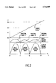
- FIG. 2 is a combined graph which includes middle and lower graphs which depict the spectral transmission characteristics of the input and output tunable electro-optical input filters of the optical channel of the night vision goggles depicted in FIG. 1, as a function of time, and an upper graph which depicts the relationship between the voltage level of the sweep signal and the spectral transmission characteristics of the input and output tunable electro-optical filters as a function of time.
- the color night vision goggles (NVG) of the present invention are binocular-type (Type 1) NVG, although this is not limiting to the present invention, e.g., the present invention is equally applicable to monocular-style NVG.
- binocular-type NVG have two parallel optical channels, one for each eye.
- FIG. 1 depicts only one of the two optical channels of the color NVG of the present invention, since both of the optical channels are identical, the description of the one optical channel is equally applicable to the other optical channel.
- the radiant energy from a low-luminance scene being viewed by the wearer of the NVG is focused by an objective lens 20 onto a front face 21 of an image intensifier tube 22 of an image intensifier device 24 of a conventional type, e.g., an image intensifier device of the type manufactured by Litton and ITT.
- the operation of the image intensifier device 24 is the same as previously described in connection with the discussion of the presently available technology.
- the photosensitive material of the photocathode of the image intensifier tube 22 releases electrons in response to the radiant energy incident on the front face 21 of the image intensifier tube 22.
- the image intensifier device 24 further includes a microchannel plate (not separately shown) provided with a multiplicity of microchannels through which pass the electrons released by the photosensitive material of the photocathode of the image intensifier tube.
- the microchannels of the microchannel plate act as an electron gain medium, so that the electrons which pass therethrough stimulate the release of a cascade of additional electrons.
- the amplified streams of electrons which are produced by the microchannels of the microchannel plate of the image intensifier device 24 form an intensified/amplified electron image of the low-luminance scene being viewed by the wearer of the NVG.
- the NVG further include a phosphor-coated display screen 26 which is excited by the electrons produced by the image intensifier device 24.
- the excited broadband phosphor of the display screen 26 emits visible light having an intensity proportional to the number of electrons per unit time which are incident thereupon.
- the phosphor-coated display screen 26 produces an intensified/amplified visible image of the low-luminance scene which may contain as much as six orders of magnitude more output radiant energy than the input radiant energy from the scene.
- the wearer of the NVG views this intensified/amplified visible image of the low-luminance scene produced by the phosphor-coated display screen 26 through an eyepiece, which in the case of the binocular-style (Type 1) NVG, includes a pair of lenses, one for each eye.
- the eyepiece lens 28 for one of the optical channels is shown in FIG. 1.
- each optical channel of the color NVG further includes an input wavelength-tunable electro-optical filter 30 positioned in front of the objective lens 20, an output wavelength-tunable electro-optical filter 32 positioned between the phosphor-coated display screen 26 and the eyepiece lens 28 (i.e., positioned behind the eyepiece lens 28), and a control circuit 34 which sequentially and synchronously steps the input and output electro-optical (E-O) filters 30 and 32 through different spectral regions or bands of the input and output radiant energy at a sufficiently high rate (e.g., 20-180 Hz) to ensure that the actual image viewed by the wearer of the color NVG is a flicker-free, full-color image of the low-luminance scene within the field-of-view of the color NVG.
- a sufficiently high rate e.g. 20-180 Hz
- the different spectral bands of the input radiant energy are three successive bands, I1, I2, and I3, respectively, in the visible and near-infrared region of sensitivity of the photosensitive material of the photocathode of the image intensifier tube 22, and the different spectral bands of the output radiant energy are the blue (B), green (G) and red (R) wavelength/color bands.
- the process of sequentially stepping the input and output E-O filters 30 and 32 through the different spectral bands can be thought of as a "temporal scanning" process, and will be referred to hereinafter as such.
- the input and output E-O filters 30 and 32 can be thought of as "temporally scanned spectral transmission filters", in that they are driven in such a manner as to sequentially transmit different spectral (color) bands of the input and output radiant energy (within the response range of the system), respectively, in respectively sequential time intervals.
- the control circuit 34 generates a control signal (preferably a voltage signal) having a frequency within the range of 20-180 Hz, e.g., 60 Hz.
- This 60 Hz control signal can be thought of as a 60 Hz "sweep signal", and will hereinafter be referred to as such.
- the sweep signal is applied to a control input of both the input and output E-O filters 30 and 32 in order to control the spectral transmission characteristics thereof in a manner which will be more fully described hereinafter.
- the sweep signal may suitably be a sawtooth or stepped (staircase) voltage waveform.
- the general terminology "ramp-shaped waveform" broadly encompass both sawtooth and stepped waveforms.
- the specific type of sweep signal which is utilized is not limiting to the present invention.
- the spectral transmission characteristics of the input and output E-O filters 30 and 32 as a function of time is depicted in the middle and lower graphs of FIG. 2, respectively.
- the upper graph of FIG. 2 depicts the voltage level of an exemplary sawtooth-shaped sweep signal.
- the voltage level of the sweep signal determines the spectral transmission characteristics of the input and output E-O filters 30 and 32.
- the input and output E-O filters 30 and 32 transmit the band I1 of the input radiant energy and the blue color band of the output radiant energy, respectively; during a second time interval t1-t2, corresponding to a voltage level of the sweep signal of between V1-V2, the input and output E-O filters 30 and 32 transmit the band I2 of the input radiant energy and the green color band of the output radiant energy, respectively; and, during a third time interval t2-t3, corresponding to a voltage level of the sweep signal of between V2-V3, the input and output E-O filters 30 and 32 transmit the band I3 of the input radiant energy and the red color band of the output radiant energy, respectively.
- the three different spectral bands (I1, I2, and I3) of the input (incoming) radiant energy from the low-luminance scene being viewed are sequentially transmitted through the input E-O filter 30 during each cycle of the sweep signal, during the successive time intervals t0-t1, t1-t2, and t2-t3, respectively, and the three different color bands (blue, green, and red) of the output radiant energy (i.e., the visible monochromatic radiant energy produced by the spectrally broadband phosphor of the display screen 26) are sequentially transmitted through the output E-O filter 32 during each cycle of the sweep signal, during the successive time intervals t0-t1, t1-t2, and t2-t3, respectively.
- each of the different colors of the visible radiant energy produced by the phosphor-coated display screen 26 reach the viewer's eyes in rapid succession, 60 times per second, and accordingly, the viewer's eyes fuse the successive single-color images together so that they appear to the viewer as a single, flicker-free, full-color image, in much the same way as sequentially excited blue, green, and red phosphors on the face of the CRT of a television set or RGB monitor are perceived by the viewer as a single, flicker-free, full color image.
- This feature of the present invention constitutes a significant advancement in the art of NVG.
- wavelength-tunable E-O filters which may be employed include those manufactured by Displaytech and Reliant Technologies.
- the E-O filters manufactured by these two companies consist of stacked polarizers (both colored and neutral), ferroelectric liquid crystal half-wave plates, and supporting glass plate structure.
- the polarization of the incoming radiant energy received by the E-O filter of this type is dependent upon the voltage applied to the ferroelectric liquid crystal half-wave plates, and thus, the spectral transmission characteristics of the E-O filter of this type is a function of the voltage applied to the ferroelectric liquid crystal half-wave plates, i.e., the E-O filter of this type is wavelength-tunable. Accordingly, by applying a sweep signal such as a sawtooth voltage waveform to the ferroelectric liquid crystal half-wave plates, the E-O filter of this type can be temporally scanned in the manner described hereinabove.
- a sweep signal such as a sawtooth voltage waveform
- the color NVG are provided with an anti-laser jamming subsystem.
- the anti-laser jamming subsystem is suitably of the type disclosed in the previously referenced U.S. patent application Ser. No. 08/697,875, to Kintz et al., which was filed on Aug. 30, 1996.
- each channel of the color NVG is provided with an optical bright source (laser) detector 40 which is positioned between the objective lens 20 and the image intensifier device 24 to detect a portion of the incoming radiant energy that passes through the input E-O filter 30 and the objective lens 20.
- each channel of the color NVG can be provided with a high current pulse detector which is integral to the power supply 44 for detecting the presence of a bright source (e.g., a laser).
- a pulse-following circuit 42 is coupled to the output of the bright source detector 40. Due to the temporal scanning of the input E-O filter 30, the incoming radiant energy which is incident upon the bright source detector 40 during each incremental scanning time interval (e.g., t0-t1, t1-t2, or t2-t3) lies within a single spectral (color) band. As such, even bright light issued by a continuous wave laser (which lies within only one of the three spectral bands transmitted by the input E-O filter 30) reaches the bright source detector 40 in the form of discrete pulses. When the bright source detector 40 receives such a train of laser pulses, it produces a corresponding train of electrical output pulses which are supplied to the pulse-following circuit 42.
- t0-t1, t1-t2, or t2-t3 the incoming radiant energy which is incident upon the bright source detector 40 during each incremental scanning time interval (e.g., t0-t1, t1-t2, or t2-t3) lies within a single spectral (color
- the pulse-following circuit 42 controls a gated power supply 44 for the image intensifier device 24 in such a manner as to gate off (shut off) the image intensifier tube and microchannel plate of the image intensifier device 24 in synchronism with the laser pulses detected by the bright source detector 40, thereby preventing the pulses from being amplified by the image intensifier tube and microchannel plate of the image intensifier device 24.
- the spectral or color band of the incoming radiant energy that includes the wavelength of the jamming laser source is effectively blocked, and the phosphor of the display screen 26 is not excited thereby, so that no visible image is produced during the time intervals when the input E-O filter 30 is tuned to that color band.
- a fixed portion of the spectrum of the incoming radiant energy from the low-luminance scene being viewed is eliminated.
- the present invention could be employed for daytime laser eye protection. More particularly, the neutral density filters would reduce the level of the incoming radiation from a scene being viewed to a level that could be handled by the image intensifier tubes. Further, the neutral density filters would reduce the level of any incident laser energy, thereby reducing the likelihood of any damage to the image intensifier tubes.
- the operation of the color daytime vision goggles (DVG) would in other respects be the same as the operation of the color NVG of the present invention, as described hereinabove.
Abstract
Description
Claims (20)
Priority Applications (1)
| Application Number | Priority Date | Filing Date | Title |
|---|---|---|---|
| US08/755,213 US5756989A (en) | 1996-11-22 | 1996-11-22 | Color night vision goggles capable of providing anti-jamming protection against pulsed and continuous wave jamming lasers |
Applications Claiming Priority (1)
| Application Number | Priority Date | Filing Date | Title |
|---|---|---|---|
| US08/755,213 US5756989A (en) | 1996-11-22 | 1996-11-22 | Color night vision goggles capable of providing anti-jamming protection against pulsed and continuous wave jamming lasers |
Publications (1)
| Publication Number | Publication Date |
|---|---|
| US5756989A true US5756989A (en) | 1998-05-26 |
Family
ID=25038191
Family Applications (1)
| Application Number | Title | Priority Date | Filing Date |
|---|---|---|---|
| US08/755,213 Expired - Lifetime US5756989A (en) | 1996-11-22 | 1996-11-22 | Color night vision goggles capable of providing anti-jamming protection against pulsed and continuous wave jamming lasers |
Country Status (1)
| Country | Link |
|---|---|
| US (1) | US5756989A (en) |
Cited By (23)
| Publication number | Priority date | Publication date | Assignee | Title |
|---|---|---|---|---|
| WO1999043016A1 (en) * | 1998-02-18 | 1999-08-26 | Litton Systems, Inc. | Multi-function observation, ranging, and sighting device |
| WO1999060787A1 (en) * | 1998-05-18 | 1999-11-25 | Litton Systems, Inc. | Night viewer and laser range finder |
| WO2000022379A1 (en) * | 1998-10-14 | 2000-04-20 | Litton Systems, Inc. | Night vision device with laser range finder |
| US6087649A (en) * | 1997-07-28 | 2000-07-11 | Litton Systems, Inc. | Night vision device having an image intensifier tube, microchannel plate and power supply for such an image intensifier tube, and method |
| WO2000051159A1 (en) * | 1999-02-22 | 2000-08-31 | Litton Systems, Inc. | Image intensifier with optimized mcp |
| WO2001063907A2 (en) | 2000-02-23 | 2001-08-30 | Tenebraex Corporation | Methods and apparatus for providing color images from monochromatic night vision and other electro-optical viewing devices |
| FR2812090A1 (en) * | 2000-07-21 | 2002-01-25 | Thomson Csf | Color night vision intensifier, has objective image path separator and intensifier with multiple input/output zones and display mechanism visual image recombination forming |
| US6401589B1 (en) | 2000-02-09 | 2002-06-11 | The United States Of America As Represented By The Secretary Of The Air Force | Limiting airborne target designating laser canopy returns |
| WO2003001551A3 (en) * | 2001-06-20 | 2003-03-06 | Litton Systems Inc | Gating a sensor using a gated power signal |
| US6576884B1 (en) | 2001-06-20 | 2003-06-10 | Litton Systems, Inc. | Method and system for gating a sensor using a gating signal |
| US20030193980A1 (en) * | 2001-06-05 | 2003-10-16 | Oleg Matveev | Device and method for invisible road illumination and imaging using preliminary pulses |
| US20030222216A1 (en) * | 2000-03-22 | 2003-12-04 | Walkenstein Jonathan A. | Low light imaging device |
| US20030231245A1 (en) * | 2002-06-12 | 2003-12-18 | Litton Systems, Inc. | Ingaas image intensifier camera |
| US20030234870A1 (en) * | 2002-06-12 | 2003-12-25 | Litton Systems, Inc. | Event synchronization for detector systems |
| US20040036013A1 (en) * | 2002-08-20 | 2004-02-26 | Northrop Grumman Corporation | Method and system for generating an image having multiple hues |
| US20050134440A1 (en) * | 1997-10-22 | 2005-06-23 | Intelligent Technolgies Int'l, Inc. | Method and system for detecting objects external to a vehicle |
| US20080157000A1 (en) * | 2004-12-29 | 2008-07-03 | Hanan Shamir | Synthetic Colour Night Vision System |
| WO2009053502A1 (en) | 2007-10-26 | 2009-04-30 | Universidad Complutense De Madrid | Glasses for safety and prevention, comprising a treated surface, for the protection and treatment of eyes in certain occupations and during sport |
| DE102010010030A1 (en) * | 2010-03-03 | 2011-09-08 | Diehl Bgt Defence Gmbh & Co. Kg | Device for representing surrounding of vehicle, has body holder carrying display unit before eye of observer with movement of observer, and process unit detecting laser radiation and identifying radiation in image |
| US20150150725A1 (en) * | 2012-06-27 | 2015-06-04 | Commissariat à l'énergie atomique et aux énergies alternatives | Device for viewing and for protection against optical radiation and solid or liquid spray |
| US9110293B2 (en) | 2011-10-17 | 2015-08-18 | Manufacturing Techniques, Inc. | Prismatic image replication for obtaining color data from a monochrome detector array |
| US10495422B2 (en) | 2017-01-31 | 2019-12-03 | Lightguard, Ltd | System with a flashing unit for temporarily impairing vision of selected occupants of an area |
| CN112057748A (en) * | 2020-10-14 | 2020-12-11 | 爱眼(广州)医疗科技有限公司 | Multi-light-source therapeutic apparatus and control method thereof |
Citations (5)
| Publication number | Priority date | Publication date | Assignee | Title |
|---|---|---|---|---|
| US5001558A (en) * | 1985-06-11 | 1991-03-19 | General Motors Corporation | Night vision system with color video camera |
| US5162647A (en) * | 1991-02-28 | 1992-11-10 | Itt Corporation | Color image intensifier device utilizing color input and output filters being offset by a slight phase lag |
| US5214503A (en) * | 1992-01-31 | 1993-05-25 | The United States Of America As Represented By The Secretary Of The Army | Color night vision camera system |
| US5233183A (en) * | 1991-07-26 | 1993-08-03 | Itt Corporation | Color image intensifier device and method for producing same |
| US5262880A (en) * | 1990-04-26 | 1993-11-16 | Ois Optical Imaging Systems, Inc. | Night vision goggle compatible liquid crystal display device |
-
1996
- 1996-11-22 US US08/755,213 patent/US5756989A/en not_active Expired - Lifetime
Patent Citations (5)
| Publication number | Priority date | Publication date | Assignee | Title |
|---|---|---|---|---|
| US5001558A (en) * | 1985-06-11 | 1991-03-19 | General Motors Corporation | Night vision system with color video camera |
| US5262880A (en) * | 1990-04-26 | 1993-11-16 | Ois Optical Imaging Systems, Inc. | Night vision goggle compatible liquid crystal display device |
| US5162647A (en) * | 1991-02-28 | 1992-11-10 | Itt Corporation | Color image intensifier device utilizing color input and output filters being offset by a slight phase lag |
| US5233183A (en) * | 1991-07-26 | 1993-08-03 | Itt Corporation | Color image intensifier device and method for producing same |
| US5214503A (en) * | 1992-01-31 | 1993-05-25 | The United States Of America As Represented By The Secretary Of The Army | Color night vision camera system |
Cited By (40)
| Publication number | Priority date | Publication date | Assignee | Title |
|---|---|---|---|---|
| US6087649A (en) * | 1997-07-28 | 2000-07-11 | Litton Systems, Inc. | Night vision device having an image intensifier tube, microchannel plate and power supply for such an image intensifier tube, and method |
| US20050134440A1 (en) * | 1997-10-22 | 2005-06-23 | Intelligent Technolgies Int'l, Inc. | Method and system for detecting objects external to a vehicle |
| US7202776B2 (en) | 1997-10-22 | 2007-04-10 | Intelligent Technologies International, Inc. | Method and system for detecting objects external to a vehicle |
| US5973315A (en) * | 1998-02-18 | 1999-10-26 | Litton Systems, Inc. | Multi-functional day/night observation, ranging, and sighting device with active optical target acquisition and method of its operation |
| WO1999043016A1 (en) * | 1998-02-18 | 1999-08-26 | Litton Systems, Inc. | Multi-function observation, ranging, and sighting device |
| WO1999060787A1 (en) * | 1998-05-18 | 1999-11-25 | Litton Systems, Inc. | Night viewer and laser range finder |
| US6072565A (en) * | 1998-05-18 | 2000-06-06 | Litton Systems, Inc. | Night vision device with improved laser range finder |
| WO2000022379A1 (en) * | 1998-10-14 | 2000-04-20 | Litton Systems, Inc. | Night vision device with laser range finder |
| WO2000051159A1 (en) * | 1999-02-22 | 2000-08-31 | Litton Systems, Inc. | Image intensifier with optimized mcp |
| US6271511B1 (en) * | 1999-02-22 | 2001-08-07 | Litton Systems, Inc. | High-resolution night vision device with image intensifier tube, optimized high-resolution MCP, and method |
| US6401589B1 (en) | 2000-02-09 | 2002-06-11 | The United States Of America As Represented By The Secretary Of The Air Force | Limiting airborne target designating laser canopy returns |
| WO2001063907A2 (en) | 2000-02-23 | 2001-08-30 | Tenebraex Corporation | Methods and apparatus for providing color images from monochromatic night vision and other electro-optical viewing devices |
| EP1277070A4 (en) * | 2000-02-23 | 2003-04-16 | Tenebraex Corp | Methods and apparatus for providing color images from monochromatic night vision and other electro-optical viewing devices |
| EP1277070A2 (en) * | 2000-02-23 | 2003-01-22 | Tenebraex Corporation | Methods and apparatus for providing color images from monochromatic night vision and other electro-optical viewing devices |
| US6911652B2 (en) | 2000-03-22 | 2005-06-28 | Jonathan A. Walkenstein | Low light imaging device |
| US20030222216A1 (en) * | 2000-03-22 | 2003-12-04 | Walkenstein Jonathan A. | Low light imaging device |
| FR2812090A1 (en) * | 2000-07-21 | 2002-01-25 | Thomson Csf | Color night vision intensifier, has objective image path separator and intensifier with multiple input/output zones and display mechanism visual image recombination forming |
| US20030193980A1 (en) * | 2001-06-05 | 2003-10-16 | Oleg Matveev | Device and method for invisible road illumination and imaging using preliminary pulses |
| WO2003001551A3 (en) * | 2001-06-20 | 2003-03-06 | Litton Systems Inc | Gating a sensor using a gated power signal |
| US6674062B2 (en) | 2001-06-20 | 2004-01-06 | Litton Systems, Inc. | Method and system for gating a sensor using a gated power signal |
| US6576884B1 (en) | 2001-06-20 | 2003-06-10 | Litton Systems, Inc. | Method and system for gating a sensor using a gating signal |
| US20030234870A1 (en) * | 2002-06-12 | 2003-12-25 | Litton Systems, Inc. | Event synchronization for detector systems |
| US20030231245A1 (en) * | 2002-06-12 | 2003-12-18 | Litton Systems, Inc. | Ingaas image intensifier camera |
| US7092013B2 (en) * | 2002-06-12 | 2006-08-15 | Litton Systems, Inc. | InGaAs image intensifier camera |
| US6970190B2 (en) * | 2002-06-12 | 2005-11-29 | Litton Systems, Inc. | Event synchronization for detector systems |
| US20040036013A1 (en) * | 2002-08-20 | 2004-02-26 | Northrop Grumman Corporation | Method and system for generating an image having multiple hues |
| US6861638B2 (en) | 2002-08-20 | 2005-03-01 | Northrop Grumman Corporation | Method and system for generating an image having multiple hues |
| US7098436B2 (en) | 2002-08-20 | 2006-08-29 | Northrop Grumman Corporation | Method and system for generating an image having multiple hues |
| WO2004019367A1 (en) * | 2002-08-20 | 2004-03-04 | Northrop Grumman Corporation | Method and system for generating an image having multiple hues using an image intensifier |
| US20050145778A1 (en) * | 2002-08-20 | 2005-07-07 | Northrop Grumman Corporation | Method and system for generating an image having multiple hues |
| US8212876B2 (en) * | 2004-12-29 | 2012-07-03 | Elbit Systems Ltd. | Synthetic colour night vision system |
| US20080157000A1 (en) * | 2004-12-29 | 2008-07-03 | Hanan Shamir | Synthetic Colour Night Vision System |
| WO2009053502A1 (en) | 2007-10-26 | 2009-04-30 | Universidad Complutense De Madrid | Glasses for safety and prevention, comprising a treated surface, for the protection and treatment of eyes in certain occupations and during sport |
| DE102010010030A1 (en) * | 2010-03-03 | 2011-09-08 | Diehl Bgt Defence Gmbh & Co. Kg | Device for representing surrounding of vehicle, has body holder carrying display unit before eye of observer with movement of observer, and process unit detecting laser radiation and identifying radiation in image |
| DE102010010030B4 (en) * | 2010-03-03 | 2013-02-21 | Diehl Bgt Defence Gmbh & Co. Kg | Device for presenting an environment |
| US9110293B2 (en) | 2011-10-17 | 2015-08-18 | Manufacturing Techniques, Inc. | Prismatic image replication for obtaining color data from a monochrome detector array |
| US20150150725A1 (en) * | 2012-06-27 | 2015-06-04 | Commissariat à l'énergie atomique et aux énergies alternatives | Device for viewing and for protection against optical radiation and solid or liquid spray |
| US10495422B2 (en) | 2017-01-31 | 2019-12-03 | Lightguard, Ltd | System with a flashing unit for temporarily impairing vision of selected occupants of an area |
| CN112057748A (en) * | 2020-10-14 | 2020-12-11 | 爱眼(广州)医疗科技有限公司 | Multi-light-source therapeutic apparatus and control method thereof |
| CN112057748B (en) * | 2020-10-14 | 2021-12-28 | 爱眼(广州)医疗科技有限公司 | Multi-light-source therapeutic apparatus and control method thereof |
Similar Documents
| Publication | Publication Date | Title |
|---|---|---|
| US5756989A (en) | Color night vision goggles capable of providing anti-jamming protection against pulsed and continuous wave jamming lasers | |
| US5729010A (en) | Night vision device localized irradiance attenuation | |
| EP0436845B1 (en) | Liquid crystal light valve goggles for eye protection | |
| Chrzanowski | Review of night vision technology | |
| US6570147B2 (en) | Color night vision apparatus | |
| US4862257A (en) | Imaging lidar system | |
| EP1836522B1 (en) | Synthetic colour night vision system | |
| US11120534B2 (en) | Color night vision goggle | |
| US7098436B2 (en) | Method and system for generating an image having multiple hues | |
| JPH02105087A (en) | Method and device for discriminating start and flight of body | |
| US5747792A (en) | Circuit and method for preventing laser jamming of night vision goggles | |
| US5051821A (en) | Low light level color image television system including electronic contrast enhancement system | |
| US5448382A (en) | Nonlinear optical scattering screen viewer | |
| EP1377996B1 (en) | Image intensifier | |
| US5485012A (en) | Method and apparatus for blind optical augmentation | |
| US4551653A (en) | Production of correction signals in a color CRT system | |
| US7109467B2 (en) | Method and system for spread spectrum gating | |
| US4280055A (en) | Microwave image converter | |
| EP1096288A2 (en) | Solid state image intensifier for viewing device | |
| KR102271555B1 (en) | Apparatus for obtaining color image | |
| US3922524A (en) | Modular biocular eyepiece for thermal image systems | |
| US3882537A (en) | Color television camera and a strip-filter suitable therefore | |
| RU1787315C (en) | Stereoscopic television system | |
| Yates et al. | Ultraviolet imaging of hydrogen flames | |
| JP2004186984A (en) | Color light quantity amplifier |
Legal Events
| Date | Code | Title | Description |
|---|---|---|---|
| AS | Assignment |
Owner name: MCDONNELL DOUGLAS CORPORATION, MISSOURI Free format text: ASSIGNMENT OF ASSIGNORS INTEREST;ASSIGNORS:BEAR, PHILIP D.;WALRATH, LARRY C,;REEL/FRAME:008315/0318 Effective date: 19961118 |
|
| AS | Assignment |
Owner name: AIR FORCE, UNITED STATES, VIRGINIA Free format text: CONFIRMATORY LICENSE;ASSIGNOR:MCDONNELL DOUGLAS CORPORATION;REEL/FRAME:008893/0182 Effective date: 19970508 |
|
| STCF | Information on status: patent grant |
Free format text: PATENTED CASE |
|
| FEPP | Fee payment procedure |
Free format text: PAYOR NUMBER ASSIGNED (ORIGINAL EVENT CODE: ASPN); ENTITY STATUS OF PATENT OWNER: LARGE ENTITY |
|
| FEPP | Fee payment procedure |
Free format text: PAYOR NUMBER ASSIGNED (ORIGINAL EVENT CODE: ASPN); ENTITY STATUS OF PATENT OWNER: LARGE ENTITY |
|
| FEPP | Fee payment procedure |
Free format text: PAYER NUMBER DE-ASSIGNED (ORIGINAL EVENT CODE: RMPN); ENTITY STATUS OF PATENT OWNER: LARGE ENTITY |
|
| FPAY | Fee payment |
Year of fee payment: 4 |
|
| AS | Assignment |
Owner name: CALIFORNIA, THE REGENTS OF THE UNIVERSITY OF, CALI Free format text: ASSIGNMENT OF ASSIGNORS INTEREST;ASSIGNOR:MCDONNELL DOUGLAS CORPORATION;REEL/FRAME:015552/0410 Effective date: 20040702 Owner name: REGENTS OF THE UNIVERSITY OF CALIFORNIA, THE, CALI Free format text: ASSIGNMENT OF ASSIGNORS INTEREST;ASSIGNOR:MCDONNELL DOUGLAS CORPORATION;REEL/FRAME:015552/0410 Effective date: 20040702 |
|
| FPAY | Fee payment |
Year of fee payment: 8 |
|
| FPAY | Fee payment |
Year of fee payment: 12 |