US5753059A - Torsionally rigid cover and method - Google Patents
Torsionally rigid cover and method Download PDFInfo
- Publication number
- US5753059A US5753059A US08/238,413 US23841394A US5753059A US 5753059 A US5753059 A US 5753059A US 23841394 A US23841394 A US 23841394A US 5753059 A US5753059 A US 5753059A
- Authority
- US
- United States
- Prior art keywords
- cover
- stiffening ribs
- cross bracing
- injection
- stiffening
- Prior art date
- Legal status (The legal status is an assumption and is not a legal conclusion. Google has not performed a legal analysis and makes no representation as to the accuracy of the status listed.)
- Expired - Fee Related
Links
Images


Classifications
-
- B—PERFORMING OPERATIONS; TRANSPORTING
- B29—WORKING OF PLASTICS; WORKING OF SUBSTANCES IN A PLASTIC STATE IN GENERAL
- B29C—SHAPING OR JOINING OF PLASTICS; SHAPING OF MATERIAL IN A PLASTIC STATE, NOT OTHERWISE PROVIDED FOR; AFTER-TREATMENT OF THE SHAPED PRODUCTS, e.g. REPAIRING
- B29C66/00—General aspects of processes or apparatus for joining preformed parts
- B29C66/50—General aspects of joining tubular articles; General aspects of joining long products, i.e. bars or profiled elements; General aspects of joining single elements to tubular articles, hollow articles or bars; General aspects of joining several hollow-preforms to form hollow or tubular articles
- B29C66/51—Joining tubular articles, profiled elements or bars; Joining single elements to tubular articles, hollow articles or bars; Joining several hollow-preforms to form hollow or tubular articles
- B29C66/52—Joining tubular articles, bars or profiled elements
- B29C66/524—Joining profiled elements
-
- B—PERFORMING OPERATIONS; TRANSPORTING
- B29—WORKING OF PLASTICS; WORKING OF SUBSTANCES IN A PLASTIC STATE IN GENERAL
- B29C—SHAPING OR JOINING OF PLASTICS; SHAPING OF MATERIAL IN A PLASTIC STATE, NOT OTHERWISE PROVIDED FOR; AFTER-TREATMENT OF THE SHAPED PRODUCTS, e.g. REPAIRING
- B29C65/00—Joining or sealing of preformed parts, e.g. welding of plastics materials; Apparatus therefor
- B29C65/02—Joining or sealing of preformed parts, e.g. welding of plastics materials; Apparatus therefor by heating, with or without pressure
-
- B—PERFORMING OPERATIONS; TRANSPORTING
- B29—WORKING OF PLASTICS; WORKING OF SUBSTANCES IN A PLASTIC STATE IN GENERAL
- B29C—SHAPING OR JOINING OF PLASTICS; SHAPING OF MATERIAL IN A PLASTIC STATE, NOT OTHERWISE PROVIDED FOR; AFTER-TREATMENT OF THE SHAPED PRODUCTS, e.g. REPAIRING
- B29C65/00—Joining or sealing of preformed parts, e.g. welding of plastics materials; Apparatus therefor
- B29C65/48—Joining or sealing of preformed parts, e.g. welding of plastics materials; Apparatus therefor using adhesives, i.e. using supplementary joining material; solvent bonding
-
- B—PERFORMING OPERATIONS; TRANSPORTING
- B29—WORKING OF PLASTICS; WORKING OF SUBSTANCES IN A PLASTIC STATE IN GENERAL
- B29C—SHAPING OR JOINING OF PLASTICS; SHAPING OF MATERIAL IN A PLASTIC STATE, NOT OTHERWISE PROVIDED FOR; AFTER-TREATMENT OF THE SHAPED PRODUCTS, e.g. REPAIRING
- B29C66/00—General aspects of processes or apparatus for joining preformed parts
- B29C66/01—General aspects dealing with the joint area or with the area to be joined
- B29C66/05—Particular design of joint configurations
- B29C66/10—Particular design of joint configurations particular design of the joint cross-sections
- B29C66/11—Joint cross-sections comprising a single joint-segment, i.e. one of the parts to be joined comprising a single joint-segment in the joint cross-section
- B29C66/112—Single lapped joints
- B29C66/1122—Single lap to lap joints, i.e. overlap joints
-
- B—PERFORMING OPERATIONS; TRANSPORTING
- B29—WORKING OF PLASTICS; WORKING OF SUBSTANCES IN A PLASTIC STATE IN GENERAL
- B29C—SHAPING OR JOINING OF PLASTICS; SHAPING OF MATERIAL IN A PLASTIC STATE, NOT OTHERWISE PROVIDED FOR; AFTER-TREATMENT OF THE SHAPED PRODUCTS, e.g. REPAIRING
- B29C66/00—General aspects of processes or apparatus for joining preformed parts
- B29C66/01—General aspects dealing with the joint area or with the area to be joined
- B29C66/05—Particular design of joint configurations
- B29C66/10—Particular design of joint configurations particular design of the joint cross-sections
- B29C66/11—Joint cross-sections comprising a single joint-segment, i.e. one of the parts to be joined comprising a single joint-segment in the joint cross-section
- B29C66/114—Single butt joints
- B29C66/1142—Single butt to butt joints
-
- B—PERFORMING OPERATIONS; TRANSPORTING
- B29—WORKING OF PLASTICS; WORKING OF SUBSTANCES IN A PLASTIC STATE IN GENERAL
- B29C—SHAPING OR JOINING OF PLASTICS; SHAPING OF MATERIAL IN A PLASTIC STATE, NOT OTHERWISE PROVIDED FOR; AFTER-TREATMENT OF THE SHAPED PRODUCTS, e.g. REPAIRING
- B29C66/00—General aspects of processes or apparatus for joining preformed parts
- B29C66/01—General aspects dealing with the joint area or with the area to be joined
- B29C66/05—Particular design of joint configurations
- B29C66/10—Particular design of joint configurations particular design of the joint cross-sections
- B29C66/12—Joint cross-sections combining only two joint-segments; Tongue and groove joints; Tenon and mortise joints; Stepped joint cross-sections
- B29C66/128—Stepped joint cross-sections
- B29C66/1282—Stepped joint cross-sections comprising at least one overlap joint-segment
-
- B—PERFORMING OPERATIONS; TRANSPORTING
- B29—WORKING OF PLASTICS; WORKING OF SUBSTANCES IN A PLASTIC STATE IN GENERAL
- B29C—SHAPING OR JOINING OF PLASTICS; SHAPING OF MATERIAL IN A PLASTIC STATE, NOT OTHERWISE PROVIDED FOR; AFTER-TREATMENT OF THE SHAPED PRODUCTS, e.g. REPAIRING
- B29C66/00—General aspects of processes or apparatus for joining preformed parts
- B29C66/01—General aspects dealing with the joint area or with the area to be joined
- B29C66/05—Particular design of joint configurations
- B29C66/10—Particular design of joint configurations particular design of the joint cross-sections
- B29C66/12—Joint cross-sections combining only two joint-segments; Tongue and groove joints; Tenon and mortise joints; Stepped joint cross-sections
- B29C66/128—Stepped joint cross-sections
- B29C66/1284—Stepped joint cross-sections comprising at least one butt joint-segment
- B29C66/12841—Stepped joint cross-sections comprising at least one butt joint-segment comprising at least two butt joint-segments
-
- B—PERFORMING OPERATIONS; TRANSPORTING
- B29—WORKING OF PLASTICS; WORKING OF SUBSTANCES IN A PLASTIC STATE IN GENERAL
- B29C—SHAPING OR JOINING OF PLASTICS; SHAPING OF MATERIAL IN A PLASTIC STATE, NOT OTHERWISE PROVIDED FOR; AFTER-TREATMENT OF THE SHAPED PRODUCTS, e.g. REPAIRING
- B29C66/00—General aspects of processes or apparatus for joining preformed parts
- B29C66/01—General aspects dealing with the joint area or with the area to be joined
- B29C66/05—Particular design of joint configurations
- B29C66/10—Particular design of joint configurations particular design of the joint cross-sections
- B29C66/14—Particular design of joint configurations particular design of the joint cross-sections the joint having the same thickness as the thickness of the parts to be joined
-
- B—PERFORMING OPERATIONS; TRANSPORTING
- B29—WORKING OF PLASTICS; WORKING OF SUBSTANCES IN A PLASTIC STATE IN GENERAL
- B29C—SHAPING OR JOINING OF PLASTICS; SHAPING OF MATERIAL IN A PLASTIC STATE, NOT OTHERWISE PROVIDED FOR; AFTER-TREATMENT OF THE SHAPED PRODUCTS, e.g. REPAIRING
- B29C70/00—Shaping composites, i.e. plastics material comprising reinforcements, fillers or preformed parts, e.g. inserts
- B29C70/04—Shaping composites, i.e. plastics material comprising reinforcements, fillers or preformed parts, e.g. inserts comprising reinforcements only, e.g. self-reinforcing plastics
- B29C70/26—Non-fibrous reinforcements only
-
- F—MECHANICAL ENGINEERING; LIGHTING; HEATING; WEAPONS; BLASTING
- F02—COMBUSTION ENGINES; HOT-GAS OR COMBUSTION-PRODUCT ENGINE PLANTS
- F02F—CYLINDERS, PISTONS OR CASINGS, FOR COMBUSTION ENGINES; ARRANGEMENTS OF SEALINGS IN COMBUSTION ENGINES
- F02F7/00—Casings, e.g. crankcases or frames
- F02F7/006—Camshaft or pushrod housings
-
- B—PERFORMING OPERATIONS; TRANSPORTING
- B29—WORKING OF PLASTICS; WORKING OF SUBSTANCES IN A PLASTIC STATE IN GENERAL
- B29C—SHAPING OR JOINING OF PLASTICS; SHAPING OF MATERIAL IN A PLASTIC STATE, NOT OTHERWISE PROVIDED FOR; AFTER-TREATMENT OF THE SHAPED PRODUCTS, e.g. REPAIRING
- B29C65/00—Joining or sealing of preformed parts, e.g. welding of plastics materials; Apparatus therefor
- B29C65/02—Joining or sealing of preformed parts, e.g. welding of plastics materials; Apparatus therefor by heating, with or without pressure
- B29C65/08—Joining or sealing of preformed parts, e.g. welding of plastics materials; Apparatus therefor by heating, with or without pressure using ultrasonic vibrations
-
- B—PERFORMING OPERATIONS; TRANSPORTING
- B29—WORKING OF PLASTICS; WORKING OF SUBSTANCES IN A PLASTIC STATE IN GENERAL
- B29C—SHAPING OR JOINING OF PLASTICS; SHAPING OF MATERIAL IN A PLASTIC STATE, NOT OTHERWISE PROVIDED FOR; AFTER-TREATMENT OF THE SHAPED PRODUCTS, e.g. REPAIRING
- B29C66/00—General aspects of processes or apparatus for joining preformed parts
- B29C66/70—General aspects of processes or apparatus for joining preformed parts characterised by the composition, physical properties or the structure of the material of the parts to be joined; Joining with non-plastics material
- B29C66/71—General aspects of processes or apparatus for joining preformed parts characterised by the composition, physical properties or the structure of the material of the parts to be joined; Joining with non-plastics material characterised by the composition of the plastics material of the parts to be joined
Definitions
- the present invention relates generally to a cover constructed of polymeric material that is substantially cup shaped and which has a bottom having stiffening ribs on its interior.
- Such covers are generally known and used, for instance, to cover belt pulleys or as the valve covers of an internal combustion engine.
- the stiffening ribs are provided in order to minimize warping of the cover caused by manufacture. The warping is caused by varying shrinkage of material in different regions of the cover so that torsion is produced along the longitudinal axis of the cover.
- Stiffening ribs which are integrally developed have the disadvantage that relatively high forces are required while fastening the cover in order to overcome the slight warping which remains, and to align the sealing surface approximately parallel to the mating surface.
- soft seals of elastomeric material such as are employed, for instance, for the acoustic decoupling of the cover, the danger exists that the cover will be mechanically overstressed and/or damaged upon its mounting.
- the instant invention provides for a method for producing a novel cup-shaped polymeric cover having stiffening ribs.
- the stiffening ribs are provided in the form of a cross bracing composed of stiffening rib elements separated from one another by clearances or gaps. These clearances are bridged by secondary connecting elements that link the ribs to each other.
- the polymeric cover is initially relatively deformable in torsion.
- a torsionally rigid cover of stable shape is subsequently obtained once the clearances are bridged by a series of secondary connecting elements, which occurs only after the cover has been straightened into the desired shape so that the fastening flange has a flat sealing surface. In this way, mechanical uniform stressing of the seal used is obtained along its entire circumference upon the mounting of the cover.
- the stiffening ribs which are adjacent to the secondary connecting element can be connected together by adhesion.
- the secondary connecting element can, for instance, be an adhesive substance.
- the use of adhesive is advantageous in that it increases the weight of the cover only insignificantly.
- Polyamide with fiberglass filling is one suitable such adhesive substance for the cover.
- the connection of the end or tip surfaces of the stiffening ribs by an adhesive substance is also advantageous from a manufacturing standpoint and is favorable in cost from an economic standpoint.
- the stiffening ribs which are contiguous to each other through the clearances, can be provided with a profiling in the region of their boundary portions that have congruently shaped surfaces. Such surface profiling helps provide a relatively large surface are on each boundary portion which increases the surface area available for the application of adhesive. Hence, adhesive connections can be improved even upon the action of mechanical and/or thermal stresses.
- the profiled boundaries may be developed, for instance, in semi-circular, trough- or L-shape.
- the secondary connecting element can be formed as a weld seam.
- the cover is made from as filler material for the welding as well. After the adjacent reinforcing ribs have been welded together, they pass into one another as an integral, single piece of the identical material. The torsional rigidity of the cover then is as great as that of a cross-wise stiffening bracing that has been formed via conventional manufacture.
- the present invention provides a uniformly flat sealing surface along the fastening flange. Subsequent straightening of the cover during mounting, as is necessary in the prior art, can therefore be avoided.
- the cover is used as an acoustically decoupled valve cover on the cylinder head of an internal combustion engine, it can be constructed of polyamide, which is resistant to hot oil mist.
- the secondary connecting element can be formed as a distinct connector body formed of the same material as the stiffening ribs and which connects the boundaries of the stiffening ribs together so that they pass into one another and form a single piece.
- the connector body can be produced, for instance, in a further injection-molding process.
- the body of material can be made as a separate individual part. In that case, it is advantageous for the connector body to have a stiffness which differs from that of the stiffening ribs so that the stiffness of the cover can thereby be controlled in the desired manner.
- the secondary connecting element can take the form of rivets, screws or clamps.
- a cover having interrupted cross bracing is produced in a first manufacturing step by injection molding. After removal from the mold, the cover is clamped with its sealing surface on a flange surface corresponding to the structural part of be covered, and the stiffening ribs of the cross bracing which are separated from one another by gaps or clearances are then connected to each other in a second manufacturing step.
- the entire plastic cover advantageously does not exhibit any of the warping caused in the manufacture of other types of such covers, so that the sealing surfaces they provide are absolutely flat.
- Such a warp-free cover can be aligned particularly easily parallel to the mating surface of the machine part to be covered.
- a seal is inserted in order to seal off the joint between the cover and the machine part, it is acted on by uniform pressure along its entire periphery by the flat parallel surfaces of the two parts which are to be fixed to each other. Leaks in partial regions of the circumferential extent of the seal can thereby be dependably avoided, and a particularly good acoustic decoupling of the two parts is attained.
- the cover is relatively torsionally weak due to the clearances or gaps in the crosswise stiffening ribs, and is clamped on a sealing plane corresponding to the plane of the structural part to be sealed.
- the boundaries of the stiffening ribs which are adjacent to each other are connected together.
- the stiffening ribs can be connected to each other by adhesion in the second manufacturing step.
- An adhesive connection can be produced in the manner that the stiffening ribs are connected together by an adhesive substance.
- a welding of the contiguous boundaries of the stiffening ribs can be effected thermally or by ultrasonics.
- the stiffening ribs can be connected to each other in the second manufacturing step by an injection-molding process. A cover which is entirely of the same material can thereby be produced.
- the cover ready for use, has a torsional rigidity which corresponds to that of a crosswise bracing which is closed on itself, in which connection warping of the cover, in particular due to difference in shrinkage upon the manufacture by the injection-molding process and stresses caused thereby, is dependably avoided.
- FIG. 1 is a view of a first embodiment of a polymeric cover, shown partially in section;
- FIG. 2 is a view of the interior of the cover of FIG. 1, in which the stiffening ribs of the bottom of the cover are seen to form a cross bracing;
- FIG. 3 shows a second embodiment of a cross bracing
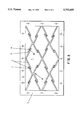
- FIG. 4 shows a third embodiment, similar to the embodiment of FIG. 2, in which the stiffening ribs having a boundary which differs from FIG. 2.
- FIG. 1 illustrates a first embodiment of a cover made of polymeric material constructed according to the principles of the invention that has been developed for use as a valve cover for an internal combustion engine.
- the bottom 1 of the cover has stiffening ribs 3 which are arranged in a cross bracing 4.
- a fastening flange 2 which extends circumferentially around the cup portion and which is provided with openings which are penetrated through by screws or bolts when the cover is mounted.
- FIG. 2 is a view of the interior of the cup-shaped cover as seen from the fastening flange 2, in which the stiffening ribs 3 which pass into and form a single piece with the cover bottom 1 are arranged to form a cross bracing 4.
- the contiguous boundaries 9, 10 of the stiffening ribs 3 are connected to each other adhesively by an adhesive substance 6.
- the boundaries 9, 10 have an L-shape, whereby the surface of the stiffening ribs is relatively enlarged in this region. The relatively enlarged surface results in a stable connection of the stiffening ribs with each other.
- the stiffening ribs 3 of the cross bracing 4 overlap each other in the region of their end boundaries 9, 10, and are welded to each other on the surfaces facing each other.
- the weld seam 7 consists of a material which corresponds to the material of the cover.
- connector bodies 8 which are attached by adhesive 6 to the boundaries 9, 10 of the stiffening ribs 3, are inserted in the clearances 5 between the stiffening ribs 3, which also form a cross bracing 4.
- the polymeric material has as high a torsional rigidity as if the stiffening ribs were developed so as to pass into each other as a single piece formed during the first manufacturing step.
- This structural rigidity is attained even though in the initial injection molding step, the cover is produced with an interrupted cross bracing by injection molding, after which the cover is clamped with its sealing surface 11 onto a flange surface corresponding to the structural part to be covered.
- the stiffening ribs 3 of the cross bracing which are contiguous to the clearances 5, are connected to each other in a subsequent manufacturing step.
- the fastening flange 2 of the cover (which, in the embodiment shown, comprises the sealing surface 11), has a flat sealing surface 11 which extends parallel to the flange surface of the structural part to be covered.
Abstract
A cover of polymeric material developed substantially in cup shape is disclosed. The bottom of the cover has stiffening ribs on its inner side. The stiffening ribs are developed as a cross bracing, the cross bracing being interrupted at least in part by gaps, the stiffening ribs being connected to each other by a secondary connecting element spanning the gaps.
Description
The present invention relates generally to a cover constructed of polymeric material that is substantially cup shaped and which has a bottom having stiffening ribs on its interior.
Such covers are generally known and used, for instance, to cover belt pulleys or as the valve covers of an internal combustion engine. The stiffening ribs are provided in order to minimize warping of the cover caused by manufacture. The warping is caused by varying shrinkage of material in different regions of the cover so that torsion is produced along the longitudinal axis of the cover. Stiffening ribs which are integrally developed have the disadvantage that relatively high forces are required while fastening the cover in order to overcome the slight warping which remains, and to align the sealing surface approximately parallel to the mating surface. Particularly when soft seals of elastomeric material are used, such as are employed, for instance, for the acoustic decoupling of the cover, the danger exists that the cover will be mechanically overstressed and/or damaged upon its mounting.
There remains a need to provide a cover of polymer material (and a method for its manufacture) that is dimensionally stable and torsionally rigid and that has a fastening flange with a flat sealing surface.
The instant invention provides for a method for producing a novel cup-shaped polymeric cover having stiffening ribs.
The stiffening ribs are provided in the form of a cross bracing composed of stiffening rib elements separated from one another by clearances or gaps. These clearances are bridged by secondary connecting elements that link the ribs to each other. As a result of the clearances within the cross bracing, the polymeric cover is initially relatively deformable in torsion. A torsionally rigid cover of stable shape is subsequently obtained once the clearances are bridged by a series of secondary connecting elements, which occurs only after the cover has been straightened into the desired shape so that the fastening flange has a flat sealing surface. In this way, mechanical uniform stressing of the seal used is obtained along its entire circumference upon the mounting of the cover.
In accordance with a first embodiment, the stiffening ribs which are adjacent to the secondary connecting element can be connected together by adhesion. In this case, the secondary connecting element can, for instance, be an adhesive substance. The use of adhesive is advantageous in that it increases the weight of the cover only insignificantly. Polyamide with fiberglass filling is one suitable such adhesive substance for the cover. The connection of the end or tip surfaces of the stiffening ribs by an adhesive substance is also advantageous from a manufacturing standpoint and is favorable in cost from an economic standpoint.
The stiffening ribs, which are contiguous to each other through the clearances, can be provided with a profiling in the region of their boundary portions that have congruently shaped surfaces. Such surface profiling helps provide a relatively large surface are on each boundary portion which increases the surface area available for the application of adhesive. Hence, adhesive connections can be improved even upon the action of mechanical and/or thermal stresses. The profiled boundaries may be developed, for instance, in semi-circular, trough- or L-shape.
In accordance with another embodiment, the secondary connecting element can be formed as a weld seam. In this case, it is advantageous to use the same polymer material that the cover is made from as filler material for the welding as well. After the adjacent reinforcing ribs have been welded together, they pass into one another as an integral, single piece of the identical material. The torsional rigidity of the cover then is as great as that of a cross-wise stiffening bracing that has been formed via conventional manufacture. However, in contrast with the latter, the present invention provides a uniformly flat sealing surface along the fastening flange. Subsequent straightening of the cover during mounting, as is necessary in the prior art, can therefore be avoided. This is particularly advantageous when the inside of the cover is acted on by heat and/or liquid media. Due to the fact that the entire cover consists of a single material, simple adaptation to the specific circumstances of the particular use is possible. For example, if the cover is used as an acoustically decoupled valve cover on the cylinder head of an internal combustion engine, it can be constructed of polyamide, which is resistant to hot oil mist.
In accordance with another embodiment, the secondary connecting element can be formed as a distinct connector body formed of the same material as the stiffening ribs and which connects the boundaries of the stiffening ribs together so that they pass into one another and form a single piece. The connector body can be produced, for instance, in a further injection-molding process. The body of material can be made as a separate individual part. In that case, it is advantageous for the connector body to have a stiffness which differs from that of the stiffening ribs so that the stiffness of the cover can thereby be controlled in the desired manner.
In accordance with another embodiment, the secondary connecting element can take the form of rivets, screws or clamps.
In order to manufacture the cover of polymer material described above, a cover having interrupted cross bracing is produced in a first manufacturing step by injection molding. After removal from the mold, the cover is clamped with its sealing surface on a flange surface corresponding to the structural part of be covered, and the stiffening ribs of the cross bracing which are separated from one another by gaps or clearances are then connected to each other in a second manufacturing step. The entire plastic cover advantageously does not exhibit any of the warping caused in the manufacture of other types of such covers, so that the sealing surfaces they provide are absolutely flat. Such a warp-free cover can be aligned particularly easily parallel to the mating surface of the machine part to be covered. If, for instance, a seal is inserted in order to seal off the joint between the cover and the machine part, it is acted on by uniform pressure along its entire periphery by the flat parallel surfaces of the two parts which are to be fixed to each other. Leaks in partial regions of the circumferential extent of the seal can thereby be dependably avoided, and a particularly good acoustic decoupling of the two parts is attained.
As noted, after the first manufacturing step, the cover is relatively torsionally weak due to the clearances or gaps in the crosswise stiffening ribs, and is clamped on a sealing plane corresponding to the plane of the structural part to be sealed. When the cover has been straightened, the boundaries of the stiffening ribs which are adjacent to each other are connected together.
The stiffening ribs can be connected to each other by adhesion in the second manufacturing step. An adhesive connection can be produced in the manner that the stiffening ribs are connected together by an adhesive substance. Furthermore, a welding of the contiguous boundaries of the stiffening ribs can be effected thermally or by ultrasonics.
In accordance with another method, the stiffening ribs can be connected to each other in the second manufacturing step by an injection-molding process. A cover which is entirely of the same material can thereby be produced.
The cover, ready for use, has a torsional rigidity which corresponds to that of a crosswise bracing which is closed on itself, in which connection warping of the cover, in particular due to difference in shrinkage upon the manufacture by the injection-molding process and stresses caused thereby, is dependably avoided.
FIG. 1 is a view of a first embodiment of a polymeric cover, shown partially in section;
FIG. 2 is a view of the interior of the cover of FIG. 1, in which the stiffening ribs of the bottom of the cover are seen to form a cross bracing;
FIG. 3 shows a second embodiment of a cross bracing; and
FIG. 4 shows a third embodiment, similar to the embodiment of FIG. 2, in which the stiffening ribs having a boundary which differs from FIG. 2.
FIG. 1 illustrates a first embodiment of a cover made of polymeric material constructed according to the principles of the invention that has been developed for use as a valve cover for an internal combustion engine. The bottom 1 of the cover has stiffening ribs 3 which are arranged in a cross bracing 4. On the side facing away from the bottom 1 of the cover there is arranged a fastening flange 2 which extends circumferentially around the cup portion and which is provided with openings which are penetrated through by screws or bolts when the cover is mounted.
FIG. 2 is a view of the interior of the cup-shaped cover as seen from the fastening flange 2, in which the stiffening ribs 3 which pass into and form a single piece with the cover bottom 1 are arranged to form a cross bracing 4. In this embodiment, the contiguous boundaries 9, 10 of the stiffening ribs 3 are connected to each other adhesively by an adhesive substance 6. The boundaries 9, 10 have an L-shape, whereby the surface of the stiffening ribs is relatively enlarged in this region. The relatively enlarged surface results in a stable connection of the stiffening ribs with each other.
In the embodiment of FIG. 3, the stiffening ribs 3 of the cross bracing 4 overlap each other in the region of their end boundaries 9, 10, and are welded to each other on the surfaces facing each other. The weld seam 7 consists of a material which corresponds to the material of the cover.
In FIG. 4 connector bodies 8, which are attached by adhesive 6 to the boundaries 9, 10 of the stiffening ribs 3, are inserted in the clearances 5 between the stiffening ribs 3, which also form a cross bracing 4.
After the setting and hardening of the adhesive 6 shown in FIGS. 2 and 4 and the cooling of the weld seam 7 of FIG. 3, the polymeric material has as high a torsional rigidity as if the stiffening ribs were developed so as to pass into each other as a single piece formed during the first manufacturing step. This structural rigidity is attained even though in the initial injection molding step, the cover is produced with an interrupted cross bracing by injection molding, after which the cover is clamped with its sealing surface 11 onto a flange surface corresponding to the structural part to be covered. Once it has been placed in the clamped condition, the stiffening ribs 3 of the cross bracing, which are contiguous to the clearances 5, are connected to each other in a subsequent manufacturing step. The fastening flange 2 of the cover (which, in the embodiment shown, comprises the sealing surface 11), has a flat sealing surface 11 which extends parallel to the flange surface of the structural part to be covered.
Claims (6)
1. A method of manufacturing a polymeric cover having a fastening flange, a plurality of sidewalls, and a bottom, comprising the steps of:
injection molding a cover so as to include a lattice of stiffening ribs connecting adjacent and opposed sidewalls and the bottom of the cover in a first step wherein the lattice of stiffening ribs has a plurality of interrupted portions;
removing the cover from the mold;
clamping the cover by its fastening flange onto a flange surface which corresponds to a structural part to be covered; and
connecting together the interrupted portions of the stiffening ribs of the lattice, thereby providing a rigid cross-bracing to the cover.
2. A method according to claim 1, wherein the stiffening ribs are connected to each other by adhesion.
3. A method according to claim 1, wherein the stiffening ribs are welded to each other thermally or by ultrasonics.
4. A method according to claim 2, wherein the stiffening ribs are welded to each other thermally or by ultrasonics.
5. A method according to claim 1, wherein the stiffening ribs are connected to each other by an injection-molding process in the final manufacturing step.
6. A method according to claim 2, wherein the stiffening ribs are connected to each other by an injection-molding process in the final manufacturing step.
Priority Applications (1)
| Application Number | Priority Date | Filing Date | Title |
|---|---|---|---|
| US08/477,249 US5636759A (en) | 1993-05-07 | 1995-06-07 | Torsionally rigid cover |
Applications Claiming Priority (2)
| Application Number | Priority Date | Filing Date | Title |
|---|---|---|---|
| DE4315149.3 | 1993-03-07 | ||
| DE4315149A DE4315149C2 (en) | 1993-05-07 | 1993-05-07 | cover |
Related Child Applications (1)
| Application Number | Title | Priority Date | Filing Date |
|---|---|---|---|
| US08/477,249 Division US5636759A (en) | 1993-05-07 | 1995-06-07 | Torsionally rigid cover |
Publications (1)
| Publication Number | Publication Date |
|---|---|
| US5753059A true US5753059A (en) | 1998-05-19 |
Family
ID=6487430
Family Applications (2)
| Application Number | Title | Priority Date | Filing Date |
|---|---|---|---|
| US08/238,413 Expired - Fee Related US5753059A (en) | 1993-03-07 | 1994-05-05 | Torsionally rigid cover and method |
| US08/477,249 Expired - Fee Related US5636759A (en) | 1993-05-07 | 1995-06-07 | Torsionally rigid cover |
Family Applications After (1)
| Application Number | Title | Priority Date | Filing Date |
|---|---|---|---|
| US08/477,249 Expired - Fee Related US5636759A (en) | 1993-05-07 | 1995-06-07 | Torsionally rigid cover |
Country Status (3)
| Country | Link |
|---|---|
| US (2) | US5753059A (en) |
| CA (1) | CA2123026C (en) |
| DE (1) | DE4315149C2 (en) |
Families Citing this family (8)
| Publication number | Priority date | Publication date | Assignee | Title |
|---|---|---|---|---|
| JP2759789B2 (en) * | 1996-06-03 | 1998-05-28 | 川崎重工業株式会社 | Small planing boat internal combustion engine |
| US6543404B2 (en) | 2001-04-04 | 2003-04-08 | Dow Global Technologies, Inc. | Adhesively bonded engine intake manifold assembly |
| US20040121674A1 (en) * | 2002-12-18 | 2004-06-24 | Robbins Jeffrey R. | Composite engine component and method for making the same |
| US7360519B2 (en) * | 2003-07-10 | 2008-04-22 | Dow Global Technologies, Inc. | Engine intake manifold assembly |
| DE202005009096U1 (en) * | 2005-06-09 | 2006-10-26 | Mann + Hummel Gmbh | Oil pan, especially for an internal combustion engine |
| US8065993B2 (en) | 2008-12-16 | 2011-11-29 | Ford Global Technologies, Llc | Structural oil baffle for engine covers |
| US9976674B2 (en) * | 2016-05-13 | 2018-05-22 | Thomas & Betts International Llc | Concrete insert channel assembly |
| CN108177848A (en) * | 2017-12-27 | 2018-06-19 | 惠州市华星光电技术有限公司 | Liquid crystal panel-packaging box |
Citations (4)
| Publication number | Priority date | Publication date | Assignee | Title |
|---|---|---|---|---|
| US4525401A (en) * | 1979-11-30 | 1985-06-25 | The Continental Group, Inc. | Plastic container with internal rib reinforced bottom |
| US4577775A (en) * | 1983-12-10 | 1986-03-25 | Gizeh-Werk Gmbh | Cup-shaped container |
| US4647325A (en) * | 1984-07-12 | 1987-03-03 | Presto Products, Incorporated | Ultrasonic spot welding tip assembly and method for using the same |
| US5032213A (en) * | 1989-02-06 | 1991-07-16 | Rampart Packaging Inc. | Thermal lid sealing method and apparatus |
Family Cites Families (8)
| Publication number | Priority date | Publication date | Assignee | Title |
|---|---|---|---|---|
| US2833163A (en) * | 1956-08-10 | 1958-05-06 | Clifford J Trombley | Marine conversion unit |
| DE8324081U1 (en) * | 1983-08-22 | 1983-11-24 | Schneider, Siegbert, Dipl.-Ing., 6920 Sinsheim | Plastic cover |
| DE3531352C1 (en) * | 1985-09-03 | 1986-10-30 | Audi AG, 8070 Ingolstadt | Oil pan for internal combustion engines |
| JPH0799087B2 (en) * | 1989-06-19 | 1995-10-25 | 日産自動車株式会社 | Cylinder head cover for internal combustion engine |
| JPH03124920A (en) * | 1989-10-11 | 1991-05-28 | Daihatsu Motor Co Ltd | Noise reduction device of cylinder head cover in internal combustion engine |
| US5129371A (en) * | 1991-09-03 | 1992-07-14 | Saturn Corporation | Cam cover oil separator for crankcase ventilation |
| JP2604399Y2 (en) * | 1992-03-26 | 2000-05-08 | 株式会社テネックス | Synthetic resin cylinder head cover |
| US5228420A (en) * | 1992-09-25 | 1993-07-20 | Tsuchiya Mfg. Co., Ltd. | Valve rocker cover |
-
1993
- 1993-05-07 DE DE4315149A patent/DE4315149C2/en not_active Expired - Lifetime
-
1994
- 1994-05-05 US US08/238,413 patent/US5753059A/en not_active Expired - Fee Related
- 1994-05-06 CA CA002123026A patent/CA2123026C/en not_active Expired - Fee Related
-
1995
- 1995-06-07 US US08/477,249 patent/US5636759A/en not_active Expired - Fee Related
Patent Citations (4)
| Publication number | Priority date | Publication date | Assignee | Title |
|---|---|---|---|---|
| US4525401A (en) * | 1979-11-30 | 1985-06-25 | The Continental Group, Inc. | Plastic container with internal rib reinforced bottom |
| US4577775A (en) * | 1983-12-10 | 1986-03-25 | Gizeh-Werk Gmbh | Cup-shaped container |
| US4647325A (en) * | 1984-07-12 | 1987-03-03 | Presto Products, Incorporated | Ultrasonic spot welding tip assembly and method for using the same |
| US5032213A (en) * | 1989-02-06 | 1991-07-16 | Rampart Packaging Inc. | Thermal lid sealing method and apparatus |
Also Published As
| Publication number | Publication date |
|---|---|
| DE4315149A1 (en) | 1994-11-10 |
| US5636759A (en) | 1997-06-10 |
| CA2123026C (en) | 1997-06-10 |
| CA2123026A1 (en) | 1994-11-08 |
| DE4315149C2 (en) | 1995-02-23 |
Similar Documents
| Publication | Publication Date | Title |
|---|---|---|
| US6609717B2 (en) | Thermoplastic gasket with edge bonded rubber apertures and integral alignment grommets | |
| US4819953A (en) | Cylinder head cover with gasket and method of making the gasket | |
| US5753059A (en) | Torsionally rigid cover and method | |
| US3990324A (en) | Vibration damper and method of making said damper | |
| US5618047A (en) | Molded gasket with a multiple component reinforcing element | |
| US7771641B2 (en) | Component part with integrated seal | |
| EP2158394A2 (en) | Valve cover assembly and method of construction | |
| MXPA06013362A (en) | Valve cover assembly for a vehicle engine and method for producing same . | |
| KR100243511B1 (en) | Tire tube manufacturing method with sealing agent | |
| JP2006194439A (en) | Method and device for manufacturing antivibration device | |
| US5152538A (en) | Composite seal assembly | |
| GB2069095A (en) | Rubber-viscous torsional vibration dampers and a method for their manufacture | |
| MX2007015478A (en) | Gasket with sealing insert. | |
| EP0821153B1 (en) | Diaphragm-holding synthetic resin assembly | |
| US4942907A (en) | Intake manifold | |
| JP3980668B2 (en) | MOUNTING DEVICE AND MANUFACTURING METHOD THEREOF | |
| US6945199B2 (en) | Engine coolant crossover assembly | |
| US4339862A (en) | Method of making rubber/viscous torsional vibration dampers | |
| US20040201181A1 (en) | Flange seal | |
| JPH0221534Y2 (en) | ||
| AU2004203205A1 (en) | Gasket having an inner edge with coined angles and method of manufacture | |
| GB2264151A (en) | Elastic ring seal | |
| EP0568205A1 (en) | Sonar transducer assembly | |
| JP3212513B2 (en) | Composite member and method of manufacturing the same | |
| JP2990290B2 (en) | Metal gasket |
Legal Events
| Date | Code | Title | Description |
|---|---|---|---|
| AS | Assignment |
Owner name: FIRMA CARL FREUDENBERG, GERMANY Free format text: ASSIGNMENT OF ASSIGNORS INTEREST;ASSIGNOR:BRUMMER, MICHAEL;REEL/FRAME:006988/0773 Effective date: 19940418 |
|
| REMI | Maintenance fee reminder mailed | ||
| LAPS | Lapse for failure to pay maintenance fees | ||
| STCH | Information on status: patent discontinuation |
Free format text: PATENT EXPIRED DUE TO NONPAYMENT OF MAINTENANCE FEES UNDER 37 CFR 1.362 |
|
| FP | Lapsed due to failure to pay maintenance fee |
Effective date: 20020519 |