US5747965A - Battery pack for powered motion furniture - Google Patents
Battery pack for powered motion furniture Download PDFInfo
- Publication number
- US5747965A US5747965A US08/613,588 US61358896A US5747965A US 5747965 A US5747965 A US 5747965A US 61358896 A US61358896 A US 61358896A US 5747965 A US5747965 A US 5747965A
- Authority
- US
- United States
- Prior art keywords
- battery
- battery pack
- circuit board
- batteries
- cavity
- Prior art date
- Legal status (The legal status is an assumption and is not a legal conclusion. Google has not performed a legal analysis and makes no representation as to the accuracy of the status listed.)
- Expired - Fee Related
Links
Images


Classifications
-
- H—ELECTRICITY
- H01—ELECTRIC ELEMENTS
- H01M—PROCESSES OR MEANS, e.g. BATTERIES, FOR THE DIRECT CONVERSION OF CHEMICAL ENERGY INTO ELECTRICAL ENERGY
- H01M6/00—Primary cells; Manufacture thereof
- H01M6/50—Methods or arrangements for servicing or maintenance, e.g. for maintaining operating temperature
- H01M6/5011—Methods or arrangements for servicing or maintenance, e.g. for maintaining operating temperature for several cells simultaneously or successively
-
- H—ELECTRICITY
- H01—ELECTRIC ELEMENTS
- H01M—PROCESSES OR MEANS, e.g. BATTERIES, FOR THE DIRECT CONVERSION OF CHEMICAL ENERGY INTO ELECTRICAL ENERGY
- H01M10/00—Secondary cells; Manufacture thereof
- H01M10/42—Methods or arrangements for servicing or maintenance of secondary cells or secondary half-cells
- H01M10/425—Structural combination with electronic components, e.g. electronic circuits integrated to the outside of the casing
- H01M10/4257—Smart batteries, e.g. electronic circuits inside the housing of the cells or batteries
-
- H—ELECTRICITY
- H01—ELECTRIC ELEMENTS
- H01M—PROCESSES OR MEANS, e.g. BATTERIES, FOR THE DIRECT CONVERSION OF CHEMICAL ENERGY INTO ELECTRICAL ENERGY
- H01M10/00—Secondary cells; Manufacture thereof
- H01M10/42—Methods or arrangements for servicing or maintenance of secondary cells or secondary half-cells
- H01M10/46—Accumulators structurally combined with charging apparatus
-
- H—ELECTRICITY
- H01—ELECTRIC ELEMENTS
- H01M—PROCESSES OR MEANS, e.g. BATTERIES, FOR THE DIRECT CONVERSION OF CHEMICAL ENERGY INTO ELECTRICAL ENERGY
- H01M50/00—Constructional details or processes of manufacture of the non-active parts of electrochemical cells other than fuel cells, e.g. hybrid cells
- H01M50/20—Mountings; Secondary casings or frames; Racks, modules or packs; Suspension devices; Shock absorbers; Transport or carrying devices; Holders
- H01M50/204—Racks, modules or packs for multiple batteries or multiple cells
- H01M50/207—Racks, modules or packs for multiple batteries or multiple cells characterised by their shape
- H01M50/209—Racks, modules or packs for multiple batteries or multiple cells characterised by their shape adapted for prismatic or rectangular cells
-
- H—ELECTRICITY
- H01—ELECTRIC ELEMENTS
- H01M—PROCESSES OR MEANS, e.g. BATTERIES, FOR THE DIRECT CONVERSION OF CHEMICAL ENERGY INTO ELECTRICAL ENERGY
- H01M50/00—Constructional details or processes of manufacture of the non-active parts of electrochemical cells other than fuel cells, e.g. hybrid cells
- H01M50/20—Mountings; Secondary casings or frames; Racks, modules or packs; Suspension devices; Shock absorbers; Transport or carrying devices; Holders
- H01M50/271—Lids or covers for the racks or secondary casings
-
- H—ELECTRICITY
- H01—ELECTRIC ELEMENTS
- H01M—PROCESSES OR MEANS, e.g. BATTERIES, FOR THE DIRECT CONVERSION OF CHEMICAL ENERGY INTO ELECTRICAL ENERGY
- H01M50/00—Constructional details or processes of manufacture of the non-active parts of electrochemical cells other than fuel cells, e.g. hybrid cells
- H01M50/20—Mountings; Secondary casings or frames; Racks, modules or packs; Suspension devices; Shock absorbers; Transport or carrying devices; Holders
- H01M50/284—Mountings; Secondary casings or frames; Racks, modules or packs; Suspension devices; Shock absorbers; Transport or carrying devices; Holders with incorporated circuit boards, e.g. printed circuit boards [PCB]
-
- Y—GENERAL TAGGING OF NEW TECHNOLOGICAL DEVELOPMENTS; GENERAL TAGGING OF CROSS-SECTIONAL TECHNOLOGIES SPANNING OVER SEVERAL SECTIONS OF THE IPC; TECHNICAL SUBJECTS COVERED BY FORMER USPC CROSS-REFERENCE ART COLLECTIONS [XRACs] AND DIGESTS
- Y02—TECHNOLOGIES OR APPLICATIONS FOR MITIGATION OR ADAPTATION AGAINST CLIMATE CHANGE
- Y02E—REDUCTION OF GREENHOUSE GAS [GHG] EMISSIONS, RELATED TO ENERGY GENERATION, TRANSMISSION OR DISTRIBUTION
- Y02E60/00—Enabling technologies; Technologies with a potential or indirect contribution to GHG emissions mitigation
- Y02E60/10—Energy storage using batteries
Definitions
- the present invention relates generally to power-assisted furniture and, more particularly, to a battery pack for providing power to an electric motor capable of reciprocating the operative components of the power-assisted furniture.
- the present invention overcomes the disadvantages associated with power-assisted furniture by providing a compact battery pack that includes a self-contained circuit board thereby allowing existing powered motion furniture to be more easily and inexpensively retrofitted with a standby power source.
- the battery pack for powered motion furniture includes a housing having connecting means for coupling the housing to the powered motion furniture.
- the housing defines a cavity within which a first battery and a second battery are disposed and electrically connected to one another in series.
- Support means are included within the cavity to structurally support a circuit board that is electrically connected to each of the first and second batteries and to the electric motor.
- the circuit board regulates the charging and discharging of the first and second batteries so as to provide a reliable standby power source for operating the power-assisted furniture.
- FIG. 2 is a top view of the chair and battery pack shown in FIG. 1;
- FIG. 3 is an exploded perspective view of the battery pack
- FIG. 4 is a top view of the battery pack with the cover and connecting wires removed for clarity;
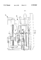
- FIG. 5 is a side view of the assembled battery pack with the side panel of the housing cover removed for clarity.
- a power-assisted lift chair 10 is shown in FIGS. 1 and 2 in an extended position.
- the components and operation of the power-assisted lift chair are not discussed in detail herein. Rather, reference may be made to commonly owned U.S. Pat. No. 5,455,046, issued Nov. 14, 1995 and entitled “Actuation Drive Mechanism For Power-Assisted Chair", for a detailed explanation and illustration of the chair.
- the frame of power-assisted lift chair 10 is shown to include a mounting tube 12 to which a battery pack 14 is connected.
- Umbilical cord 16 electrically connects battery pack 14 to an electric motor 18 that is, in turn, connected to an AC power source (not shown) through a power cord 20.
- Battery pack 14 is shown in detail in FIG. 3 to include a housing 22 having a cover 24 and a base 26, first and second rechargeable batteries 28 and 30, respectively, a spacer plate 32, and a circuit board 34.
- First and second batteries 28 and 30, respectively each include a positive terminal 36 and 38, respectively, and a negative terminal 40 and 42, respectively.
- first and second batteries 28 and 30, respectively are connected to one another in series and electrically connected to circuit board 34 which is connected to electric motor 18 through plug fitting 43 of umbilical cord 16.
- While the battery pack described and claimed herein is intended to accommodate a variety of styles and models of rechargeable batteries, it is specifically contemplated that a maintenance free, rechargeable battery such as types NP15-12 or NP24-12, manufactured by Yuasa Battery Co., Ltd. of Santa Fe Springs, Calif. be used.
- a maintenance free, rechargeable battery such as types NP15-12 or NP24-12, manufactured by Yuasa Battery Co., Ltd. of Santa Fe Springs, Calif. be used.
- a maintenance free, rechargeable battery such as types NP15-12 or NP24-12, manufactured by Yuasa Battery Co., Ltd. of Santa Fe Springs, Calif. be used.
- a maintenance free, rechargeable battery such as types NP15-12 or NP24-12, manufactured by Yuasa Battery Co., Ltd. of Santa Fe Springs, Calif. be used.
- One of the desirable features provided by these batteries is that they include a low pressure venting system operative between 7 psi and 10 psi to release excess gas and res
- the batteries will be oriented in an upright configuration
- the preferred batteries have a sealed construction that allows them to operate in most any position without adversely effecting the capacity of the electrolytes or the service life of the batteries.
- each of the preferred batteries have a capacity such that, when connected in series, the capacity of the battery pack is sufficient to reciprocate the power-assisted chair through multiple cycles, preferably at least twenty (20) cycles, before recharging.
- venting means 46 for circulating air from and into housing cavity 44.
- venting means 46 includes a pair of holes 48 formed in the top surface 50 of housing cover 24. Specifically, the contemplated holes are located along the transverse centerline 52 of housing cover 24 and are formed so as to have a diameter of approximately 0.045 inches.
- first and second batteries 28 and 30, respectively are connected to one another in series as shown in a generally schematic fashion in FIG. 3.
- the preferred connection includes a connector wire 54 electrically connecting the positive terminal 36 of the first battery 28 to circuit board 34, a second connector wire 56 connecting the negative terminal 40 of first battery 28 to the positive terminal 38 of second battery 30, and a third connector wire 58 electrically connecting the negative terminal 42 of second battery 30 to circuit board 34.
- the first and second batteries can be serially connected in a manner different from that shown in FIG. 3 and, moreover, that additional batteries may be provided and connected together either serially or in parallel without departing from the scope of the invention described and claimed herein.
- Housing 22 includes coupling means for connecting cover 24 to base 26 which, in the preferred embodiment, includes first and second connector plates 60 and 62 extending upwardly from base 26 and each defining an aperture 64 and 66, respectively.
- Cover 24 includes apertures 70 through which threaded connector bolts 72 or similar connecting members such as plastic rivets are disposed to secure cover 24 to base 26.
- base 26 includes connecting means for securing housing 22 to the powered motion furniture.
- the preferred connecting means illustrated in the drawings includes apertures 74 formed in base 26 to cooperate with connector bolts 76 which secure battery pack 14 to the powered motion furniture such as through apertures (not shown) formed in mounting tube 12.
- Base 26 further includes an opening 68 through which umbilical cord 16 enters cavity 44. It should be appreciated by those skilled in the art that a variety of coupling means and/or connecting means may be used without departing from the scope of the claimed invention.
- Circuit board 34 regulates the charging and discharging of first and second batteries 28 and 30, respectively, in a manner known in the art.
- the present invention include a charging/discharging circuit board manufactured by Maxwell Products of Cerritos, Calif. or an equivalent thereof.
- the charging circuit board should include a current sensing circuit that enables a charging circuit to provide a charging current to first and second batteries 28 and 30 when power cord 20 of electric motor 18 is connected to an operative AC power source.
- the charging circuit is capable of rapidly charging the battery after a deep discharge as well as providing a trickle charge to maintain the batteries in a substantially fully charged condition.
- the circuit board also operates to discharge current from the serially connected batteries through umbilical cord 16 when the power cord 20 is disconnected from the external AC power source.
- first battery 28 is disposed upon and structurally supported by base 26 of housing 22. While base 26 is shown as a plate-like member capable of accommodating first battery 28 in a variety of positions, it is contemplated that base 26 may be formed in a variety of configurations including as a molded member having a compartment specifically sized and positioned to retain first battery 28 in a predetermined location.
- Spacer plate 32 preferably formed by stamping or machining a sheet of ABS thermoplastic material such as fire retardant KJB material sold by Borg-Warner under the CYCOLAC trademark, is disposed in contacting relation with a top surface 80 of first battery 28.
- Spacer plate 32 generally includes cut-outs 84, an aperture 86 with a pair of opposing notches 88, a bottom surface 90, and a top surface 92.
- Top and bottom surfaces 90 and 92, respectively, are separated by a continuous side wall 94 of uniform height that circumscribes the periphery of spacer plate 32. It should be appreciated that the desired thickness of spacer plate 32, i.e., the length of side wall 94, is dependent in part upon the required spacing between first and second batteries 28 and 30, respectively.
- the recommended free air space between the preferred NP15-12 or NP24-12 batteries by Yuasa Battery Co. is 0.02 to 0.04 inches.
- spacer plate 32 is positioned relative to first battery 28 such that cut-outs 84 accommodate the positive and negative battery terminals, 36 and 40, respectively, of first battery 28.
- the cut-outs 84 allow spacer plate bottom surface 90 to contact top surface 80 of first battery 28.
- the positive and negative battery terminals 36, 38, 40, and 42 of first and second batteries 28 and 30, respectively are comprised of tab type terminals such as the Faston Tab 250 terminals included with Yuasa battery NP15-12, one skilled in the art will appreciate that bolt type terminals such as those included with Yuasa battery NP24-12 may also be used.
- Second battery 30 is positioned above first battery 28 and rests upon upper surface 92 of spacer plate 32 whereby first and second batteries 28 and 30, respectively, are disposed in a vertically stacked arrangement separated by spacer plate 32.
- first battery 28 is offset forwardly of a rear wall 98 of cover 24 in order to accommodate the portion of connector bolts 72 that extend into housing cavity 44.
- a rear surface 100 of second battery 30 is in close proximity to or in contacting relationship with rear wall 98. It should be appreciated by those skilled in the art that first and second batteries 28 and 30, respectively, can be fixedly secured in their respective positions relative to housing 22 by means known in the art.
- support means for securing circuit board 34 within housing cavity 44 preferably includes opposing notches 88 formed in first aperture 86 of spacer plate 32.
- Each of the opposing notches 88 are sized such that the opposing notch walls are spaced from one another a distance equal to or slightly larger than the thickness 104 of circuit board 34 (FIG. 4). Accordingly, the walls defining notch 88 frictionally engage and support circuit board 34 therebetween while aperture 86 is sized so as to accommodate the operative components of circuit board 34 as well as to provide the necessary clearance to connect connector wires 54 and 58, umbilical cord 16, and any other necessary components thereto (FIG. 5). As further shown in FIG.
- spacer plate 32 within housing cavity 44 is that a front surface 106 of spacer plate 32 contacts a front wall 108 of cover 24. It will be appreciated that variations to the specific orientation and structure of spacer plate 32 and circuit board 34 may be made by those skilled in the art without departing from the scope of the appended claims.
- the battery pack for powered motion furniture described herein provides a compact and durable reserve power system for powered motion furniture.
- the present invention allows existing powered motion furniture to be more easily and inexpensively retrofitted with the present invention.
Abstract
Description
Claims (20)
Priority Applications (1)
| Application Number | Priority Date | Filing Date | Title |
|---|---|---|---|
| US08/613,588 US5747965A (en) | 1996-03-12 | 1996-03-12 | Battery pack for powered motion furniture |
Applications Claiming Priority (1)
| Application Number | Priority Date | Filing Date | Title |
|---|---|---|---|
| US08/613,588 US5747965A (en) | 1996-03-12 | 1996-03-12 | Battery pack for powered motion furniture |
Publications (1)
| Publication Number | Publication Date |
|---|---|
| US5747965A true US5747965A (en) | 1998-05-05 |
Family
ID=24457892
Family Applications (1)
| Application Number | Title | Priority Date | Filing Date |
|---|---|---|---|
| US08/613,588 Expired - Fee Related US5747965A (en) | 1996-03-12 | 1996-03-12 | Battery pack for powered motion furniture |
Country Status (1)
| Country | Link |
|---|---|
| US (1) | US5747965A (en) |
Cited By (16)
| Publication number | Priority date | Publication date | Assignee | Title |
|---|---|---|---|---|
| EP1006597A2 (en) * | 1998-11-30 | 2000-06-07 | Sony Corporation | Battery device for loading on a mobile system |
| US20040206556A1 (en) * | 2002-04-20 | 2004-10-21 | Siegfried Fricker | Carriage |
| US20060188724A1 (en) * | 2003-02-18 | 2006-08-24 | Sony Chemical Corp | Liquid absorbing sheet and nonaqueous electrolyte battery pack |
| US20070184337A1 (en) * | 2006-01-18 | 2007-08-09 | Masatoshi Nagayama | Battery operated device |
| EP1850407A1 (en) * | 2005-02-16 | 2007-10-31 | Toyota Jidosha Kabushiki Kaisha | Battery pack and automobile |
| US20080116845A1 (en) * | 2004-10-14 | 2008-05-22 | Underwater Technologies Center Ltd. | Arrangement For Charging a Battery of an Underwater Portable Apparatus, Which Prevents Discharge of the Battery When the Apparatus is Underwater |
| US20110137484A1 (en) * | 2003-06-09 | 2011-06-09 | Big Belly Solar, Inc. | Electrically-powered programmable package deposit enclosure |
| US20110165451A1 (en) * | 2010-01-05 | 2011-07-07 | Myung-Chul Kim | Battery pack |
| US8608240B2 (en) | 2011-09-09 | 2013-12-17 | La-Z-Boy Incorporated | Mechanism and chair for powered combined and independent seat back and leg rest motion |
| US8915544B2 (en) | 2011-08-26 | 2014-12-23 | La-Z-Boy Incorporated | Furniture member with mechanism for powered occupant lift |
| US9010851B2 (en) | 2013-09-19 | 2015-04-21 | La-Z-Boy Incorporated | Furniture member power mechanism with selectable lift movement and zero gravity position |
| US9326606B2 (en) | 2013-09-19 | 2016-05-03 | La-Z-Boy Incorporated | Furniture member power mechanism with zero gravity and rear tilt positions |
| US9358167B2 (en) | 2013-09-19 | 2016-06-07 | La-Z-Boy Incorporated | Furniture member power mechanism with selectable lift movement and zero gravity position |
| US9660236B2 (en) | 2013-11-06 | 2017-05-23 | Yamaha Hatsudoki Kabushiki Kaisha | Battery and saddle-type electric vehicle equipped therewith |
| US20180072184A1 (en) * | 2016-09-13 | 2018-03-15 | Honda Motor Co., Ltd | Vehicular charging part layout structure |
| US11605838B2 (en) * | 2019-01-30 | 2023-03-14 | Era Nouveau, LLC | Furniture efficient battery pack |
Citations (18)
| Publication number | Priority date | Publication date | Assignee | Title |
|---|---|---|---|---|
| US3111181A (en) * | 1961-07-05 | 1963-11-19 | George D Yatich | Powered wheelchair |
| US3846179A (en) * | 1972-08-16 | 1974-11-05 | Saft Batteries Ltd | Battery cell spacer |
| US3933522A (en) * | 1974-06-04 | 1976-01-20 | Accumulatorenfabriken Wilhelm Hagen Ag | Accumulator cell |
| US4113926A (en) * | 1976-08-20 | 1978-09-12 | Chloride Group Limited | Cell racks |
| US4231614A (en) * | 1978-10-27 | 1980-11-04 | Shaffer Gene P | Wheelchair |
| US4407543A (en) * | 1981-10-30 | 1983-10-04 | David Mashuda | Mechanized wheelchair |
| US4655471A (en) * | 1986-01-13 | 1987-04-07 | Peek Gregory A | Wheelchair having adjustable backrest |
| US5036938A (en) * | 1989-03-13 | 1991-08-06 | Blount Wendell G | Disassemblable riding scooter |
| US5044647A (en) * | 1989-11-17 | 1991-09-03 | Folio Products, Inc. | Stabilized reclining wheelchair seat |
| US5193633A (en) * | 1991-06-07 | 1993-03-16 | Wright State University | Motorized transfer and transport system for the disabled |
| US5297021A (en) * | 1992-11-16 | 1994-03-22 | Koerlin James M | Zero shear recliner/tilt wheelchair seat |
| US5304434A (en) * | 1992-06-15 | 1994-04-19 | Gnb Industrial Battery Co. | Modular cabinet for large-sized sealed lead-acid cells |
| US5366036A (en) * | 1993-01-21 | 1994-11-22 | Perry Dale E | Power stand-up and reclining wheelchair |
| US5437939A (en) * | 1994-01-06 | 1995-08-01 | Gnb Industrial Battery Company | Sealed lead-acid battery tray assemblies and motive power vehicles using such battery tray assemblies |
| US5441123A (en) * | 1993-04-01 | 1995-08-15 | Gnb Battery Technologies Inc. | Sealed lead-acid cell tray assembly and motive powered vehicle using such cell tray assembly |
| US5497066A (en) * | 1994-02-23 | 1996-03-05 | D & D Advanced Technologies, Inc. | Battery booster system |
| US5531284A (en) * | 1992-06-02 | 1996-07-02 | Quickie Designs Inc. | Powered wheelchair with a detachable power drive assembly |
| US5592997A (en) * | 1993-08-23 | 1997-01-14 | Ball; Richard D. | Pediatric wheelchair |
-
1996
- 1996-03-12 US US08/613,588 patent/US5747965A/en not_active Expired - Fee Related
Patent Citations (18)
| Publication number | Priority date | Publication date | Assignee | Title |
|---|---|---|---|---|
| US3111181A (en) * | 1961-07-05 | 1963-11-19 | George D Yatich | Powered wheelchair |
| US3846179A (en) * | 1972-08-16 | 1974-11-05 | Saft Batteries Ltd | Battery cell spacer |
| US3933522A (en) * | 1974-06-04 | 1976-01-20 | Accumulatorenfabriken Wilhelm Hagen Ag | Accumulator cell |
| US4113926A (en) * | 1976-08-20 | 1978-09-12 | Chloride Group Limited | Cell racks |
| US4231614A (en) * | 1978-10-27 | 1980-11-04 | Shaffer Gene P | Wheelchair |
| US4407543A (en) * | 1981-10-30 | 1983-10-04 | David Mashuda | Mechanized wheelchair |
| US4655471A (en) * | 1986-01-13 | 1987-04-07 | Peek Gregory A | Wheelchair having adjustable backrest |
| US5036938A (en) * | 1989-03-13 | 1991-08-06 | Blount Wendell G | Disassemblable riding scooter |
| US5044647A (en) * | 1989-11-17 | 1991-09-03 | Folio Products, Inc. | Stabilized reclining wheelchair seat |
| US5193633A (en) * | 1991-06-07 | 1993-03-16 | Wright State University | Motorized transfer and transport system for the disabled |
| US5531284A (en) * | 1992-06-02 | 1996-07-02 | Quickie Designs Inc. | Powered wheelchair with a detachable power drive assembly |
| US5304434A (en) * | 1992-06-15 | 1994-04-19 | Gnb Industrial Battery Co. | Modular cabinet for large-sized sealed lead-acid cells |
| US5297021A (en) * | 1992-11-16 | 1994-03-22 | Koerlin James M | Zero shear recliner/tilt wheelchair seat |
| US5366036A (en) * | 1993-01-21 | 1994-11-22 | Perry Dale E | Power stand-up and reclining wheelchair |
| US5441123A (en) * | 1993-04-01 | 1995-08-15 | Gnb Battery Technologies Inc. | Sealed lead-acid cell tray assembly and motive powered vehicle using such cell tray assembly |
| US5592997A (en) * | 1993-08-23 | 1997-01-14 | Ball; Richard D. | Pediatric wheelchair |
| US5437939A (en) * | 1994-01-06 | 1995-08-01 | Gnb Industrial Battery Company | Sealed lead-acid battery tray assemblies and motive power vehicles using such battery tray assemblies |
| US5497066A (en) * | 1994-02-23 | 1996-03-05 | D & D Advanced Technologies, Inc. | Battery booster system |
Cited By (27)
| Publication number | Priority date | Publication date | Assignee | Title |
|---|---|---|---|---|
| EP1006597A2 (en) * | 1998-11-30 | 2000-06-07 | Sony Corporation | Battery device for loading on a mobile system |
| EP1006597A3 (en) * | 1998-11-30 | 2000-06-14 | Sony Corporation | Battery device for loading on a mobile system |
| US6472098B1 (en) | 1998-11-30 | 2002-10-29 | Sony Corporation | Battery device for loading on a mobile system |
| AU2003232608B2 (en) * | 2002-04-20 | 2008-09-11 | Siegfried Fricker | Carriage |
| US7021408B2 (en) * | 2002-04-20 | 2006-04-04 | Siegfried Fricker | Carriage |
| US20040206556A1 (en) * | 2002-04-20 | 2004-10-21 | Siegfried Fricker | Carriage |
| CN1646357B (en) * | 2002-04-20 | 2010-09-01 | 西格弗里德·弗里克 | Carriage for container |
| US20060188724A1 (en) * | 2003-02-18 | 2006-08-24 | Sony Chemical Corp | Liquid absorbing sheet and nonaqueous electrolyte battery pack |
| US7399531B2 (en) * | 2003-02-18 | 2008-07-15 | Sony Corporation | Liquid absorbing sheet and nonaqueous electrolyte battery pack |
| US10602867B2 (en) * | 2003-06-09 | 2020-03-31 | Big Belly Solar, Inc. | Electrically-powered programmable storage containers |
| US20110137484A1 (en) * | 2003-06-09 | 2011-06-09 | Big Belly Solar, Inc. | Electrically-powered programmable package deposit enclosure |
| US11944218B2 (en) | 2003-06-09 | 2024-04-02 | Big Belly Solar Llc | System and method of providing packing inventory sensing and management of a supply compartment for a storage receptacle |
| US20080116845A1 (en) * | 2004-10-14 | 2008-05-22 | Underwater Technologies Center Ltd. | Arrangement For Charging a Battery of an Underwater Portable Apparatus, Which Prevents Discharge of the Battery When the Apparatus is Underwater |
| EP1850407A1 (en) * | 2005-02-16 | 2007-10-31 | Toyota Jidosha Kabushiki Kaisha | Battery pack and automobile |
| US20070284167A1 (en) * | 2005-02-16 | 2007-12-13 | Toyota Jidosha Kabushiki Kaisha | Battery Pack and Motor Vehicle |
| EP1850407A4 (en) * | 2005-02-16 | 2008-05-21 | Toyota Motor Co Ltd | Battery pack and automobile |
| US20070184337A1 (en) * | 2006-01-18 | 2007-08-09 | Masatoshi Nagayama | Battery operated device |
| US20110165451A1 (en) * | 2010-01-05 | 2011-07-07 | Myung-Chul Kim | Battery pack |
| US8915544B2 (en) | 2011-08-26 | 2014-12-23 | La-Z-Boy Incorporated | Furniture member with mechanism for powered occupant lift |
| US8608240B2 (en) | 2011-09-09 | 2013-12-17 | La-Z-Boy Incorporated | Mechanism and chair for powered combined and independent seat back and leg rest motion |
| US9010851B2 (en) | 2013-09-19 | 2015-04-21 | La-Z-Boy Incorporated | Furniture member power mechanism with selectable lift movement and zero gravity position |
| US9326606B2 (en) | 2013-09-19 | 2016-05-03 | La-Z-Boy Incorporated | Furniture member power mechanism with zero gravity and rear tilt positions |
| US9358167B2 (en) | 2013-09-19 | 2016-06-07 | La-Z-Boy Incorporated | Furniture member power mechanism with selectable lift movement and zero gravity position |
| US9660236B2 (en) | 2013-11-06 | 2017-05-23 | Yamaha Hatsudoki Kabushiki Kaisha | Battery and saddle-type electric vehicle equipped therewith |
| EP2871125B1 (en) * | 2013-11-06 | 2020-07-15 | Yamaha Hatsudoki Kabushiki Kaisha | Battery and saddle-type electric vehicle equipped therewith |
| US20180072184A1 (en) * | 2016-09-13 | 2018-03-15 | Honda Motor Co., Ltd | Vehicular charging part layout structure |
| US11605838B2 (en) * | 2019-01-30 | 2023-03-14 | Era Nouveau, LLC | Furniture efficient battery pack |
Similar Documents
| Publication | Publication Date | Title |
|---|---|---|
| US5747965A (en) | Battery pack for powered motion furniture | |
| US5350317A (en) | Battery pack | |
| US5248927A (en) | Battery pack with temperature detecting element and battery charger therefor | |
| CA2120441C (en) | Sealed lead-acid cell tray assembly and motive powered vehicle using such cell tray assembly | |
| US6494279B1 (en) | Battery enclosure system for motive power in hazardous service environments | |
| US6204632B1 (en) | Apparatus for charging multiple batteries | |
| US5172043A (en) | Energy using device | |
| US3348116A (en) | Electric knife storage case and battery charger | |
| US5689171A (en) | Battery charger | |
| US5429585A (en) | Multi-function cushion | |
| US5142123A (en) | Electric heat sealer energizable by internal battery set or external AC adapter | |
| US6597152B1 (en) | Battery charger splitting adapter | |
| ES2129985T3 (en) | LAWN MOWER WITH ACCUMULATOR. | |
| GB2104732A (en) | Supply and protection unit for a hermetic compressor | |
| US5703751A (en) | Electrical apparatus with a detachable power supply base | |
| CA2265374A1 (en) | Control module for battery faucet | |
| EP0295340B1 (en) | Electrical connection for battery charging apparatus or the like | |
| EP0716495B1 (en) | Battery charger | |
| JP3350957B2 (en) | Battery pack | |
| JP3672021B2 (en) | Cordless tool | |
| CN112716455A (en) | Sleep monitor | |
| JP3672029B2 (en) | Cordless tool | |
| CN219226371U (en) | Rechargeable accumulator for medical equipment | |
| CN217215313U (en) | Charging pile | |
| CN215267764U (en) | Novel UPS power supply device |
Legal Events
| Date | Code | Title | Description |
|---|---|---|---|
| AS | Assignment |
Owner name: LA-Z-BOY CHAIR COMPANY, MICHIGAN Free format text: ASSIGNMENT OF ASSIGNORS INTEREST;ASSIGNORS:LAPOINTE, LARRY P.;SAUL, JONATHAN R.;REEL/FRAME:007904/0188 Effective date: 19960306 |
|
| AS | Assignment |
Owner name: LA-Z-BOY INCORPORATED, MICHIGAN Free format text: CHANGE OF NAME;ASSIGNOR:LA-Z-BOY CHAIR COMPANY;REEL/FRAME:008167/0972 Effective date: 19960816 |
|
| FPAY | Fee payment |
Year of fee payment: 4 |
|
| REMI | Maintenance fee reminder mailed | ||
| FPAY | Fee payment |
Year of fee payment: 8 |
|
| AS | Assignment |
Owner name: WACHOVIA CAPITAL FINANCE CORPORATION (CENTRAL), AS Free format text: SECURITY AGREEMENT;ASSIGNORS:LA-Z-BOY INCORPORATED;KINCAID FURNITURE COMPANY, INCORPORATED;ENGLAND, INC.;AND OTHERS;REEL/FRAME:020487/0199 Effective date: 20080206 |
|
| REMI | Maintenance fee reminder mailed | ||
| LAPS | Lapse for failure to pay maintenance fees | ||
| LAPS | Lapse for failure to pay maintenance fees |
Free format text: PATENT EXPIRED FOR FAILURE TO PAY MAINTENANCE FEES (ORIGINAL EVENT CODE: EXP.); ENTITY STATUS OF PATENT OWNER: LARGE ENTITY |
|
| STCH | Information on status: patent discontinuation |
Free format text: PATENT EXPIRED DUE TO NONPAYMENT OF MAINTENANCE FEES UNDER 37 CFR 1.362 |
|
| FP | Lapsed due to failure to pay maintenance fee |
Effective date: 20100505 |