US5739671A - Device for accurate detection of remaining discharge capacities of a plurality of batteries - Google Patents
Device for accurate detection of remaining discharge capacities of a plurality of batteries Download PDFInfo
- Publication number
- US5739671A US5739671A US08/647,657 US64765796A US5739671A US 5739671 A US5739671 A US 5739671A US 64765796 A US64765796 A US 64765796A US 5739671 A US5739671 A US 5739671A
- Authority
- US
- United States
- Prior art keywords
- battery
- batteries
- capacity
- voltage
- charge state
- Prior art date
- Legal status (The legal status is an assumption and is not a legal conclusion. Google has not performed a legal analysis and makes no representation as to the accuracy of the status listed.)
- Expired - Fee Related
Links
Images


Classifications
-
- H—ELECTRICITY
- H02—GENERATION; CONVERSION OR DISTRIBUTION OF ELECTRIC POWER
- H02J—CIRCUIT ARRANGEMENTS OR SYSTEMS FOR SUPPLYING OR DISTRIBUTING ELECTRIC POWER; SYSTEMS FOR STORING ELECTRIC ENERGY
- H02J7/00—Circuit arrangements for charging or depolarising batteries or for supplying loads from batteries
- H02J7/0013—Circuit arrangements for charging or depolarising batteries or for supplying loads from batteries acting upon several batteries simultaneously or sequentially
- H02J7/0014—Circuits for equalisation of charge between batteries
- H02J7/0018—Circuits for equalisation of charge between batteries using separate charge circuits
-
- G—PHYSICS
- G01—MEASURING; TESTING
- G01R—MEASURING ELECTRIC VARIABLES; MEASURING MAGNETIC VARIABLES
- G01R31/00—Arrangements for testing electric properties; Arrangements for locating electric faults; Arrangements for electrical testing characterised by what is being tested not provided for elsewhere
- G01R31/36—Arrangements for testing, measuring or monitoring the electrical condition of accumulators or electric batteries, e.g. capacity or state of charge [SoC]
- G01R31/382—Arrangements for monitoring battery or accumulator variables, e.g. SoC
- G01R31/3842—Arrangements for monitoring battery or accumulator variables, e.g. SoC combining voltage and current measurements
-
- G—PHYSICS
- G01—MEASURING; TESTING
- G01R—MEASURING ELECTRIC VARIABLES; MEASURING MAGNETIC VARIABLES
- G01R31/00—Arrangements for testing electric properties; Arrangements for locating electric faults; Arrangements for electrical testing characterised by what is being tested not provided for elsewhere
- G01R31/36—Arrangements for testing, measuring or monitoring the electrical condition of accumulators or electric batteries, e.g. capacity or state of charge [SoC]
- G01R31/396—Acquisition or processing of data for testing or for monitoring individual cells or groups of cells within a battery
-
- H—ELECTRICITY
- H01—ELECTRIC ELEMENTS
- H01M—PROCESSES OR MEANS, e.g. BATTERIES, FOR THE DIRECT CONVERSION OF CHEMICAL ENERGY INTO ELECTRICAL ENERGY
- H01M10/00—Secondary cells; Manufacture thereof
- H01M10/42—Methods or arrangements for servicing or maintenance of secondary cells or secondary half-cells
- H01M10/46—Accumulators structurally combined with charging apparatus
-
- G—PHYSICS
- G01—MEASURING; TESTING
- G01R—MEASURING ELECTRIC VARIABLES; MEASURING MAGNETIC VARIABLES
- G01R31/00—Arrangements for testing electric properties; Arrangements for locating electric faults; Arrangements for electrical testing characterised by what is being tested not provided for elsewhere
- G01R31/36—Arrangements for testing, measuring or monitoring the electrical condition of accumulators or electric batteries, e.g. capacity or state of charge [SoC]
- G01R31/374—Arrangements for testing, measuring or monitoring the electrical condition of accumulators or electric batteries, e.g. capacity or state of charge [SoC] with means for correcting the measurement for temperature or ageing
-
- Y—GENERAL TAGGING OF NEW TECHNOLOGICAL DEVELOPMENTS; GENERAL TAGGING OF CROSS-SECTIONAL TECHNOLOGIES SPANNING OVER SEVERAL SECTIONS OF THE IPC; TECHNICAL SUBJECTS COVERED BY FORMER USPC CROSS-REFERENCE ART COLLECTIONS [XRACs] AND DIGESTS
- Y02—TECHNOLOGIES OR APPLICATIONS FOR MITIGATION OR ADAPTATION AGAINST CLIMATE CHANGE
- Y02E—REDUCTION OF GREENHOUSE GAS [GHG] EMISSIONS, RELATED TO ENERGY GENERATION, TRANSMISSION OR DISTRIBUTION
- Y02E60/00—Enabling technologies; Technologies with a potential or indirect contribution to GHG emissions mitigation
- Y02E60/10—Energy storage using batteries
-
- Y—GENERAL TAGGING OF NEW TECHNOLOGICAL DEVELOPMENTS; GENERAL TAGGING OF CROSS-SECTIONAL TECHNOLOGIES SPANNING OVER SEVERAL SECTIONS OF THE IPC; TECHNICAL SUBJECTS COVERED BY FORMER USPC CROSS-REFERENCE ART COLLECTIONS [XRACs] AND DIGESTS
- Y02—TECHNOLOGIES OR APPLICATIONS FOR MITIGATION OR ADAPTATION AGAINST CLIMATE CHANGE
- Y02T—CLIMATE CHANGE MITIGATION TECHNOLOGIES RELATED TO TRANSPORTATION
- Y02T10/00—Road transport of goods or passengers
- Y02T10/60—Other road transportation technologies with climate change mitigation effect
- Y02T10/70—Energy storage systems for electromobility, e.g. batteries
Definitions
- the present invention relates to a charge state detecting device for a battery device including a plurality of batteries connected in series.
- a predetermined voltage for supplying the electric motor is generated by connecting a plurality of batteries in series.
- Each of the batteries is formed from rechargeable battery cells.
- battery characteristics such as capacitance and internal resistance, are hardly identical.
- a certain battery may be overcharged, the other battery may be overdischarged, causing the lifetime of the batteries to shorten.
- Japanese Patent Application Laid-Open No. Hei 6-141479 discloses that charge and discharge of batteries are forcibly stopped when a voltage difference between a pair of batteries exceeds a predetermined value. As also disclosed therein, when there is just a pair of batteries in a battery device, detecting the voltage difference therebetween is relatively easy. The possibility of, for example, being overdischarged can be determined as a function of the voltage difference. However, when more than two batteries are employed, it is difficult to determine an overdischarge with regard to each of the batteries based on voltage differences among them. Thus, discharges from the batteries might be erroneously continued in spite of the fact that any one or more of the batteries have been fully discharged.
- Japanese Utility Model Application Laid-Open No. Hei 2-136445 discloses that voltage generated at each battery is detected; a battery charge is stopped when any one of the detected voltages has reached a charge stop voltage and a battery discharge is stopped when any one of the detected voltages has dropped to a discharge stop voltage.
- an overcharge and an overdischarge are determined based on the detected voltages, an accurate determination of being overcharged or overdischarged cannot be made. That is, a voltage value of a battery varies depending on, for example, temperature. Therefore, the voltage value does not accurately show a capacity to supply an electric power to an electric load.
- Japanese Patent Application Laid-Open No. Hei 5-64377 and family member U.S. Pat. No. 5,387,857 disclose that voltage generated at each battery is detected, and the charge currents flowing to the batteries are stopped when any one of the detected voltages have reached a full-charged voltage. Since the charge currents are stopped when a predetermined condition is fulfilled, overcharges in the batteries will not occur. However, the batteries which run short of charge are left as they are. In addition, as described as one of the disadvantages of the device disclosed by the Japanese Utility Model application Laid-Open No. Hei 2-136445, a voltage value of a battery does not accurately show the electric power supplying capacity left in the battery.
- Japanese Patent application Laid-Open No. Hei 6-133465 discloses that after any one of the batteries has reached a predetermined voltage, the charge for the batteries connected in series is continued with a reduced current so that the voltage of the battery having the predetermined voltage will not go up higher and the reminder of the batteries will approach the predetermined voltage.
- Japanese Patent Application Laid-Open No. Hei 4-299032 and family member disclose that when at least one of the batteries becomes a full charge, supplying of a charge current to the batteries will be stopped.
- Japanese Utility Model Application Laid-Open No. Sho 62-173077 discloses that the respective voltages of the batteries are compared with predetermined voltage values and if at least one of the voltages is lower than the predetermined voltage value, a warning circuit will be energized.
- Japanese Examined Patent Application No. Sho 61-22912 discloses that the respective voltages of the batteries are changed to voltage values that show how far they are from the same standard voltage, after that, the changed voltage values are compared with predetermined voltage values to determine the overdischarge.
- Japanese Patent Application Laid-Open No. Hei 5-15076 discloses that after the batteries are completely discharged so that the capacity of the each battery becomes approximately equal, the batteries are charged by a power source.
- the present invention is made in light of the foregoing problems, and it is an object of the present invention to provide a precise determination of an electric power supplying capacity left in the battery which has the least power supplying capacity among the batteries in a battery device.
- an exemplary device has a battery device including a plurality of batteries connected in series, a current detection device which detects a current flowing from the battery device, and a voltage detection device which detects the voltage of each of the batteries.
- the exemplary device further includes a capacity calculating device for calculating an electric power supplying capacity of each battery from the discharge currents and the discharge voltages of the batteries, and a capacity determination device for determining a minimum capacity among the calculated capacities.
- the capacity calculating device calculates a current-voltage regression formula, which shows a correlation relationship between a discharge current and a discharge voltage, based on plural data of the discharge currents and the discharge voltages, and provides an estimated voltage for each of the batteries under a constant energy discharge, based on the current-voltage regression formula.
- the estimated voltages are used for deriving the respective capacities of the batteries with reference to a voltage-capacity characteristic, which is stored in advance.
- an exemplary device When a battery device is used with an electric motor vehicle, it is preferable for an exemplary device to include a detectable signal producing device for producing a detectable signal which indicates at least when one of the batteries reaches a predetermined minimum desired energy supplying capacity.
- a detectable signal producing device for producing a detectable signal which indicates at least when one of the batteries reaches a predetermined minimum desired energy supplying capacity.
- a signal may energize a warning light and/or a voice generator which provides a voice warning.
- the signal may be a continuous one which represents the energy supplying capacity of whichever battery currently has the least energy supplying capacity.
- Such a continuous signal may be applied to a gauge for continuously displaying the current capacity of the battery supplying the least energy, and the gauge itself can have a red-warning area for indicating when the capacity of the least energy supplying battery reaches the predetermined minimum-desired energy supplying capacity. Since the driver can be informed by one of the warning methods that a battery has reached the predetermined minimum-des
- the exemplary device may further include an average capacity calculating device for calculating an average capacity of all batteries and a deterioration determination device for determining the deterioration of a battery when its capacity is smaller by a predetermined value than the average capacity.
- the batteries are individually charged by corresponding charge circuits. Thus, none of the batteries is overcharged. It is preferable that each battery is charged with relatively large constant current until each battery voltage reaches a predetermined value and, after that, with relatively small constant current. By charging with two kinds of constant currents, the batteries can be not only charged rapidly and without energy loss but also prevented from being overcharged.
- the period of time for charging each battery may be controlled so that the energy which is necessary to charge a battery device does not exceed the maximum energy of the power source. For example, the timing at which each battery begins to be charged is shifted from one to another, or staggered individually or in groups, or in any desired manner so that at no time are all of the time periods for charging the batteries overlapping.
- FIG. 1 is a block diagram illustrating a charge state controlling device according to the present invention
- FIG. 2 is a block diagram illustrating a structure of a communication interface 24 in FIG. 1;
- FIG. 3 is a block diagram illustrating a structure of a communication interface 31 in FIG. 1;
- FIG. 4 is a combination of FIGS. 4A and 4B;
- FIG. 4A is a flow chart illustrating the process performed by the main CPU of FIG. 1 when a battery device is charged;
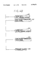
- FIG. 4B shows flow charts illustrating the processes performed by individual control circuits of FIG. 1 when a battery device is charged
- FIG. 5 is a flow chart illustrating the process performed by the main CPU and individual control circuits of FIG. 1 when a battery device is discharged;
- FIG. 6 is a time chart illustrating changes of charge current and battery voltage
- FIG. 7 is a graph illustrating a voltage characteristic under constant energy discharge.
- a battery device 1 for an electric motor vehicle is constructed by connecting a plurality of batteries 11A, 11B, . . . , 11N in series.
- Each of the batteries 11A-11N has a well-known structure including a plurality of battery cells.
- Temperature sensors 4, which detect battery temperatures, are disposed in each of batteries 11A-11N.
- An electric load 8 is connected across battery device 1 with an electric line 61.
- a load relay 71 is disposed between electric load 8 and battery device 1 to control the energy supply from battery device 1 to electric load 8.
- current sensor 5 is also disposed between electric load 8 and battery device 1.
- Individual control circuits 2A, 2B, . . . , 2N are provided, respectively, corresponding to batteries 11A-11N.
- Individual control circuits 2A-2N have the same structures including a voltage signal generator 21, a temperature signal generator 22, a battery charger 23, and a communication interface (I/F) 24.
- a pair of charge lines extending from battery charger 23 are connected via a pair of lines 62 and 63 to electrode terminals of the corresponding battery 11A-11N.
- Voltage signal generator 21 generates a voltage signal in proportion to a voltage across a pair of lines 62 and 63 (i.e., a voltage of the respective one of batteries 11A-11N).
- Temperature signal generator 22 is connected to the respective temperature sensor 4 and generates a temperature signal in proportion to the battery temperature detected by temperature sensor 4.
- communication I/F 24 has two photoelectric transducers 24a and 24b, a frequency/voltage transducer 24c, a pulse width control circuit 24d and a voltage/frequency transducer 24e.
- Voltage signal generator 21 is connected to voltage/frequency transducer 24e and temperature signal generator 22 is connected to pulse width control circuit 24d.
- the voltage signal generated by voltage signal generator 21 and temperature signal generated by temperature signal generator 22 are fed to voltage/frequency transducer 24e and pulse width control circuit 24d.
- Communication I/F 24 generates a voltage-temperature pulse signal which has a frequency that varies in response to the voltage signal from voltage signal generator 21 and a pulse width that varies in response to the temperature signal from temperature signal generator 22. After the voltage-temperature pulse signal is transduced to an optical pulse signal, the optical pulse signal is sent out by photoelectric transducer 24b.
- Frequency/voltage transducer 24c is connected to battery charger 23.
- battery charger 23 is connected to an outside (home or commercial) energy source through a charge relay 72.
- Photoelectric transducer 24a receives a photo command signal from a main controller 3 and transduces the photo command signal into an electric command signal. After that, the electric command signal is changed at frequency/voltage transducer 24c to a voltage command signal having a voltage corresponding to the frequency of the electric command signal.
- the voltage signal is fed to battery charger 23 of the respective control circuit 2A-2N.
- the command signal instructs a charge current.
- Battery charger 23 controls the charge current supplied to the corresponding battery 11A-11N in response to the command signal.
- Communication I/F 24 of each individual control circuit 2A-2N is connected by an optical fiber cable 64 to a communication I/F 31 in the main controller 3.
- Cable 64 contains a plurality of optical fibers which are respectively wired from the control circuits 2A-2N to the main controller 3.
- communication I/F 31 has two photoelectric transducers 31a and 31b, a counter timer 31c and a frequency control circuit 31d. Though not shown, communication I/F 31 contains a set of two photoelectric transducers, a counter timer and a frequency control circuit for each of the control circuits 11A-11N, and each set operates as follows.
- the optical voltage-temperature pulse signal is fed to a corresponding photoelectric transducer 31a of communication I/F 31 via cable 64 in order to change to an electric voltage-temperature signal.
- Counter timer 31c demodulates the electric voltage-temperature pulse signal into the voltage signal and the temperature signal. That is, counter timer 31c measures the frequency and pulse width of the voltage-temperature pulse signal and generates the voltage signal corresponding to the measured frequency and the temperature signal corresponding to the measured pulse width.
- a central processing unit (CPU) 32 is included in the main controller 32.
- CPU 32 is fed the voltage signals and the temperature signals from individual control circuits 2A-2N after demodulation by counter timer 31c.
- CPU 32 is also fed a current signal from current sensor 5.
- CPU 32 determines charge currents supplied to batteries 11A-11N as a function of the voltage signals, the temperature signals and the current signal.
- CPU 32 calculates the electrical power supplying capacities left in each battery 11A-11N and generates an indication signal, which causes an indicator 33 to indicate a minimum capacity among them, i.e., the capacity of the battery which currently has the least energy supplying capacity.
- the charge currents determined by CPU 32 are provided as command signals to frequency control circuits 31d of communication I/F 31, respectively.
- Frequency control circuit 31d generates a charge pulse signal with frequency in proportion to the digital value of the command signal.
- the charge pulse signals are transmitted to each control circuit 2A-2N via optical fiber cable 64.
- Frequency/voltage transducer 24c of each control circuit 2A-2N demodulates the charge pulse signal into the voltage command signal fed to battery charger 23.
- No special communication protocol is used for communications between main controller 3 and individual control circuits 2A-2N. Accordingly, control circuits 2A-2N do not need to have a CPU, which contributes to lower the cost of the device.
- FIGS. 4A and 4B show the processes performed by main controller 3 and individual control circuits 2A-2N in detail when battery device 1 is charged by an outside energy source.
- a charge switch (not shown) is turned on by an operator, a relay energizing circuit (not shown) opens load relay 71 and closes charge relay 72, which operation puts CPU 32 of main controller 3 into a charge control mode (step 101).
- CPU 32 sets a charge timer (step 102). All batteries 11A-11N start to be charged at the same time.
- the charge timer provides the longest charging period of time for batteries 11A-11N. If batteries 11A-11N continue to be charged beyond the longest charging period of time, batteries 11A-11N will be overcharged. Therefore, the charge timer is used for limiting the charging period of time against all batteries 11A-11N so as to avoid the overcharge of the batteries 11A-11N.
- CPU 32 sends out charge pulse signals (step 103) to all of the individual control circuits 2A-2N.
- the charge pulse signals are demodulated into voltage command signals to be fed to battery chargers 23.
- battery chargers 23 charge batteries 11A-11N with first constant currents, respectively (step 201). The voltages of batteries 11A-11N gradually go up because of the charges with the first constant currents (See FIG. 6).
- Steps 104 to 112 executed by main controller 3 will be explained. Steps 104 to 112 are independently processed with regard to each control circuit 2A-2N.
- CPU 32 detects a battery voltage and a battery temperature in response to the voltage-temperature pulse signal generated from each control circuit 2A-2N (step 104, step 202).
- a reference voltage is compensated depending on the detected temperature (step 105) according to the following equation;
- V0 is a constant value
- ⁇ is a coefficient
- T0 is a constant value
- T shows the detected temperature.
- the reference voltage is a reference value to determine whether a battery is close to full charge (e.g., 80%-90% of full charge). Even if a charge state of a battery does not change, the reference voltage reduces in response to an increase of the battery temperature. Therefore, the reference voltage must be compensated for an accurate determination.
- Step 106 determines whether the battery voltage exceeds the reference voltage.
- main controller 3 provides a second charge pulse signal to the corresponding control circuit 2A-2N (step 107).
- CPU 32 sets a second charge timer to limit a period of time of supplying a second constant current (step 107).
- battery charger 23 charges the corresponding battery 11A-11N with the second constant current (step 203).
- the second constant current is smaller than the first constant current as shown in FIG. 6. While the second constant current continues to flow, CPU 32 monitors whether the second charge timer exceeds a predetermined time value (step 108).
- CPU 32 determines the battery temperature and battery voltage based on the voltage-temperature pulse signal transmitted from the respective control circuit 11A-11N (step 109, step 203). Subsequently, an upper limit voltage is compensated as a function of the battery temperature (step 110) with the same manner as the reference voltage.
- Step 111 determines whether the battery voltage exceeds an upper limit voltage. When the determination at step 108 or step 111 is affirmative, CPU 32 stops the second charge pulse signal provided to the respective control circuit 2A-2N (step 112). That control circuit 2A-2N then terminates charging the battery whose voltage exceeded the upper limit voltage (step 205).
- Main controller 3 terminates the charge control mode when the charge with the second constant current has been completed in regard to all batteries 11A-11N or when the charge timer set to limit a charging period of time against all batteries 11A-11N exceeds a predetermined time value (step 113).
- the respective period of time for charging each battery 11A-11N may be controlled so that the energy needed for charging battery device 1 does not exceed the maximum energy of the power source. For example, the timing at which each battery 11A-11N begins to be charged is shifted from one to another, or staggered individually or in groups or in any desired manner so that at no time are all of the periods for charging batteries 11A-11N overlapping.
- batteries 11A-11N can be optimally charged regardless of characteristic differences among batteries 11A-11N.
- FIG. 5 shows the processes performed by main controller 3 and individual control circuits 2A-2N in detail when battery device 1 is being discharged, i.e., used to power load 8.
- a relay energizing circuit (not shown) closes load relay 71 and opens charge relay 72, to put CPU 32 of main controller 3 into a discharge control mode (step 301).
- CPU 32 detects a discharge current from battery device 1 in response to a current signal from current sensor 5 (step 302) at every predetermined constant interval.
- CPU 32 also determines the battery voltage and battery temperature for each of the batteries 11A-11N based on voltage-temperature pulse signals transmitted from control circuits 2A-2N in the same manner as described above (step 302) at every predetermined constant interval.
- Main controller 3 stores a predetermined number of discharge currents, battery voltages and battery temperatures in regard to each of batteries 11A-11N (step 303). Old data is deleted so that the predetermined number of updated data can be stored. Subsequently, main controller 3 calculates the electrical power supplying capacity (%) left in each battery 11A-11N with reference to a voltage-capacity characteristic, which is stored as a map beforehand. As shown in FIG. 7, the stored map includes a plurality of relationships between a discharge voltage and an electric power supplying capacity, in correspondence to the change of the battery temperature.
- a current-voltage regression formula is calculated to a first degree based on the predetermined number of discharge currents and battery voltages.
- the discharge current and the battery voltage have a correlation in which the smaller the battery voltage becomes, the larger the discharge current becomes according to a certain gradient.
- the current-voltage regression formula shows the correlation between the discharge current and the battery voltage.
- an estimated voltage for each battery 11A-11N under a constant energy discharge is calculated from the current-voltage regression formula. That is, when an amount of energy needed for driving an electric motor vehicle is determined, a combination of a battery voltage and a discharge current to supply the determined energy can be derived from the current-voltage regression formula.
- the electric power supplying capacity of each battery 11A-11N is derived with reference to the voltage-capacity characteristic based on the estimated battery voltage and the detected battery temperature (step 304).
- the voltage-capacity characteristic includes a plurality of relationships (FIG. 7) between a discharge voltage and an electric power supplying capacity when the battery temperature is used as a parameter. However, when the detected battery temperature does not correspond to the temperature used as a parameter, the calculated capacity is compensated by the difference therebetween according to FIG. 7.
- the minimum capacity among them is determined and is indicated on indicator 33 (steps 305 and 306).
- the indication of the minimum capacity urges a driver of the electric motor vehicle to recharge battery device 1 before the battery having the minimum capacity is overdischarged, thereby preventing battery deterioration.
- a voice generator (not shown) may be used to inform the driver.
- CPU 32 may generate a detectable signal to energize a warning light or voice generator.
- the signal may be a continuous one which represents the energy supplying capacity of whichever battery currently has the least energy supplying capacity.
- Such a continuous signal may be applied to a gauge (not shown) for continuously displaying the current capacity of the battery supplying the least energy, and the gauge itself can have a red-warning area for indicating when the capacity of the least energy supplying battery reaches the predetermined minimum-desired energy supplying capacity.
- the driver can be informed by one of the warning methods that one of batteries 11A-11N has reached the predetermined minimum-desired energy supplying capacity, the driver can take a remedial measure such as recharging battery device 1 before any of batteries 11A-11N is overdischarged.
- Main controller 3 also calculates an average capacity of all batteries 11A-11N (step 307).
- the indicated battery capacity that is, the minimum capacity
- main controller 3 determines that the battery with the minimum capacity has deteriorated and indicates that information on indicator 33 (step 309).
- the driver can accurately notice when the battery should be exchanged. It is preferable that each battery is given a number and indicator 33 indicates the number of the deteriorated battery.
- the charge state of a battery is determined based on a battery voltage when the battery is charged.
- a discharge state of a battery is determined based on an estimated battery voltage under a constant energy discharge.
- the determination of the charge state and discharge state are not limited to the mode described above.
- the discharge state can be determined based on an estimated battery voltage under a constant current discharge.
Abstract
A charge state detecting device has a battery device including a plurality of batteries connected in series, a current sensor which detects a current flowing from the battery device, and a voltage sensor which detects the voltage of each of the batteries. A main controller calculates a correlation between discharge current and battery voltage, and provides an estimated voltage of each battery of the batteries under a constant energy discharge, based on the correlation. The estimated voltages for the batteries are used for deriving the capacity of each battery with reference to a voltage-capacity characteristic, which is stored in advance. The main controller supplies to a display indicator the minimum one of the derived capacities to warn of an impending need to charge the batteries.
Description
This application is based upon and claims priority from Japanese Patent Application No. Hei 7-115748 filed May 15, 1995, the contents of which are incorporated herein by reference.
1. Field of the Invention
The present invention relates to a charge state detecting device for a battery device including a plurality of batteries connected in series.
2. Related Art
In an electric motor vehicle, a predetermined voltage for supplying the electric motor is generated by connecting a plurality of batteries in series. Each of the batteries is formed from rechargeable battery cells. However, even if batteries of the same type are employed, battery characteristics, such as capacitance and internal resistance, are hardly identical. As a result, even when the batteries are charged and discharged repeatedly under the same condition, a certain battery may be overcharged, the other battery may be overdischarged, causing the lifetime of the batteries to shorten.
Japanese Patent Application Laid-Open No. Hei 6-141479 discloses that charge and discharge of batteries are forcibly stopped when a voltage difference between a pair of batteries exceeds a predetermined value. As also disclosed therein, when there is just a pair of batteries in a battery device, detecting the voltage difference therebetween is relatively easy. The possibility of, for example, being overdischarged can be determined as a function of the voltage difference. However, when more than two batteries are employed, it is difficult to determine an overdischarge with regard to each of the batteries based on voltage differences among them. Thus, discharges from the batteries might be erroneously continued in spite of the fact that any one or more of the batteries have been fully discharged.
Japanese Utility Model Application Laid-Open No. Hei 2-136445 discloses that voltage generated at each battery is detected; a battery charge is stopped when any one of the detected voltages has reached a charge stop voltage and a battery discharge is stopped when any one of the detected voltages has dropped to a discharge stop voltage. However, since an overcharge and an overdischarge are determined based on the detected voltages, an accurate determination of being overcharged or overdischarged cannot be made. That is, a voltage value of a battery varies depending on, for example, temperature. Therefore, the voltage value does not accurately show a capacity to supply an electric power to an electric load. In addition, when batteries are used for an electric motor vehicle, it is not preferable that discharges from the batteries are stopped when one of the batteries drops to a predetermined voltage. That is because, if operated in that manner, an electric motor vehicle will come to a sudden stop regardless of the place where the electric motor vehicle is running.
Japanese Patent Application Laid-Open No. Hei 5-64377 and family member U.S. Pat. No. 5,387,857 disclose that voltage generated at each battery is detected, and the charge currents flowing to the batteries are stopped when any one of the detected voltages have reached a full-charged voltage. Since the charge currents are stopped when a predetermined condition is fulfilled, overcharges in the batteries will not occur. However, the batteries which run short of charge are left as they are. In addition, as described as one of the disadvantages of the device disclosed by the Japanese Utility Model application Laid-Open No. Hei 2-136445, a voltage value of a battery does not accurately show the electric power supplying capacity left in the battery.
Japanese Patent application Laid-Open No. Hei 6-133465 discloses that after any one of the batteries has reached a predetermined voltage, the charge for the batteries connected in series is continued with a reduced current so that the voltage of the battery having the predetermined voltage will not go up higher and the reminder of the batteries will approach the predetermined voltage.
Japanese Patent Application Laid-Open No. Hei 4-299032 and family member disclose that when at least one of the batteries becomes a full charge, supplying of a charge current to the batteries will be stopped.
Japanese Utility Model Application Laid-Open No. Sho 62-173077 discloses that the respective voltages of the batteries are compared with predetermined voltage values and if at least one of the voltages is lower than the predetermined voltage value, a warning circuit will be energized.
Japanese Examined Patent Application No. Sho 61-22912 discloses that the respective voltages of the batteries are changed to voltage values that show how far they are from the same standard voltage, after that, the changed voltage values are compared with predetermined voltage values to determine the overdischarge.
Japanese Patent Application Laid-Open No. Hei 5-15076 discloses that after the batteries are completely discharged so that the capacity of the each battery becomes approximately equal, the batteries are charged by a power source.
As is apparent, none of the prior art described above copes with the need to know the remaining power supplying capacity of the one battery which has the least power supplying capacity among a plurality of series-connected batteries.
The present invention is made in light of the foregoing problems, and it is an object of the present invention to provide a precise determination of an electric power supplying capacity left in the battery which has the least power supplying capacity among the batteries in a battery device.
It is an another object of the present invention to provide a proper charge to each battery regardless of the charge state of each of the other batteries and preventing overcharge of any battery in the battery device.
For attaining the first object, an exemplary device according to the present invention has a battery device including a plurality of batteries connected in series, a current detection device which detects a current flowing from the battery device, and a voltage detection device which detects the voltage of each of the batteries. The exemplary device further includes a capacity calculating device for calculating an electric power supplying capacity of each battery from the discharge currents and the discharge voltages of the batteries, and a capacity determination device for determining a minimum capacity among the calculated capacities.
The capacity calculating device calculates a current-voltage regression formula, which shows a correlation relationship between a discharge current and a discharge voltage, based on plural data of the discharge currents and the discharge voltages, and provides an estimated voltage for each of the batteries under a constant energy discharge, based on the current-voltage regression formula. The estimated voltages are used for deriving the respective capacities of the batteries with reference to a voltage-capacity characteristic, which is stored in advance.
Since the capacities of all of the batteries are calculated and a minimum capacity among the calculated capacities is determined, it can be accurately determined whether a battery device is able to continue supplying an electrical power to an electric load without any battery being damaged.
When a battery device is used with an electric motor vehicle, it is preferable for an exemplary device to include a detectable signal producing device for producing a detectable signal which indicates at least when one of the batteries reaches a predetermined minimum desired energy supplying capacity. Such a signal may energize a warning light and/or a voice generator which provides a voice warning. Alternatively, the signal may be a continuous one which represents the energy supplying capacity of whichever battery currently has the least energy supplying capacity. Such a continuous signal may be applied to a gauge for continuously displaying the current capacity of the battery supplying the least energy, and the gauge itself can have a red-warning area for indicating when the capacity of the least energy supplying battery reaches the predetermined minimum-desired energy supplying capacity. Since the driver can be informed by one of the warning methods that a battery has reached the predetermined minimum-desired energy supplying capacity, the driver can take a remedial measure such as recharging the battery device before any of its batteries is overdischarged.
The exemplary device may further include an average capacity calculating device for calculating an average capacity of all batteries and a deterioration determination device for determining the deterioration of a battery when its capacity is smaller by a predetermined value than the average capacity.
In the exemplary device, the batteries are individually charged by corresponding charge circuits. Thus, none of the batteries is overcharged. It is preferable that each battery is charged with relatively large constant current until each battery voltage reaches a predetermined value and, after that, with relatively small constant current. By charging with two kinds of constant currents, the batteries can be not only charged rapidly and without energy loss but also prevented from being overcharged.
When a battery device is connected to a power source for charging purposes, the period of time for charging each battery may be controlled so that the energy which is necessary to charge a battery device does not exceed the maximum energy of the power source. For example, the timing at which each battery begins to be charged is shifted from one to another, or staggered individually or in groups, or in any desired manner so that at no time are all of the time periods for charging the batteries overlapping.
Other features and advantages of the present invention will be appreciated, as well as methods of operation and the function of the related parts, from a study of the following detailed description, the appended claims, and the drawings, all of which form a part of this application. In the drawings:
FIG. 1 is a block diagram illustrating a charge state controlling device according to the present invention;
FIG. 2 is a block diagram illustrating a structure of a communication interface 24 in FIG. 1;
FIG. 3 is a block diagram illustrating a structure of a communication interface 31 in FIG. 1;
FIG. 4 is a combination of FIGS. 4A and 4B;
FIG. 4A is a flow chart illustrating the process performed by the main CPU of FIG. 1 when a battery device is charged;
FIG. 4B shows flow charts illustrating the processes performed by individual control circuits of FIG. 1 when a battery device is charged;
FIG. 5 is a flow chart illustrating the process performed by the main CPU and individual control circuits of FIG. 1 when a battery device is discharged;
FIG. 6 is a time chart illustrating changes of charge current and battery voltage; and
FIG. 7 is a graph illustrating a voltage characteristic under constant energy discharge.
A preferred embodiment of a charge state detecting device of the present invention is now described in detail with reference to FIGS. 1 to 7. In FIG. 1, a battery device 1 for an electric motor vehicle is constructed by connecting a plurality of batteries 11A, 11B, . . . , 11N in series. Each of the batteries 11A-11N has a well-known structure including a plurality of battery cells. Temperature sensors 4, which detect battery temperatures, are disposed in each of batteries 11A-11N. An electric load 8 is connected across battery device 1 with an electric line 61. A load relay 71 is disposed between electric load 8 and battery device 1 to control the energy supply from battery device 1 to electric load 8. In addition, current sensor 5 is also disposed between electric load 8 and battery device 1.
As shown in FIG. 2, communication I/F 24 has two photoelectric transducers 24a and 24b, a frequency/voltage transducer 24c, a pulse width control circuit 24d and a voltage/frequency transducer 24e.
Frequency/voltage transducer 24c is connected to battery charger 23. To charge battery device 1, battery charger 23 is connected to an outside (home or commercial) energy source through a charge relay 72. Photoelectric transducer 24a receives a photo command signal from a main controller 3 and transduces the photo command signal into an electric command signal. After that, the electric command signal is changed at frequency/voltage transducer 24c to a voltage command signal having a voltage corresponding to the frequency of the electric command signal. The voltage signal is fed to battery charger 23 of the respective control circuit 2A-2N. The command signal instructs a charge current. Battery charger 23 controls the charge current supplied to the corresponding battery 11A-11N in response to the command signal.
Communication I/F 24 of each individual control circuit 2A-2N is connected by an optical fiber cable 64 to a communication I/F 31 in the main controller 3. Cable 64 contains a plurality of optical fibers which are respectively wired from the control circuits 2A-2N to the main controller 3.
As shown in FIG. 3, communication I/F 31 has two photoelectric transducers 31a and 31b, a counter timer 31c and a frequency control circuit 31d. Though not shown, communication I/F 31 contains a set of two photoelectric transducers, a counter timer and a frequency control circuit for each of the control circuits 11A-11N, and each set operates as follows.
The optical voltage-temperature pulse signal is fed to a corresponding photoelectric transducer 31a of communication I/F 31 via cable 64 in order to change to an electric voltage-temperature signal. Counter timer 31c demodulates the electric voltage-temperature pulse signal into the voltage signal and the temperature signal. That is, counter timer 31c measures the frequency and pulse width of the voltage-temperature pulse signal and generates the voltage signal corresponding to the measured frequency and the temperature signal corresponding to the measured pulse width.
A central processing unit (CPU) 32 is included in the main controller 32. CPU 32 is fed the voltage signals and the temperature signals from individual control circuits 2A-2N after demodulation by counter timer 31c. CPU 32 is also fed a current signal from current sensor 5. CPU 32 determines charge currents supplied to batteries 11A-11N as a function of the voltage signals, the temperature signals and the current signal. In addition, CPU 32 calculates the electrical power supplying capacities left in each battery 11A-11N and generates an indication signal, which causes an indicator 33 to indicate a minimum capacity among them, i.e., the capacity of the battery which currently has the least energy supplying capacity.
The charge currents determined by CPU 32 are provided as command signals to frequency control circuits 31d of communication I/F 31, respectively. Frequency control circuit 31d generates a charge pulse signal with frequency in proportion to the digital value of the command signal. The charge pulse signals are transmitted to each control circuit 2A-2N via optical fiber cable 64. Frequency/voltage transducer 24c of each control circuit 2A-2N demodulates the charge pulse signal into the voltage command signal fed to battery charger 23. No special communication protocol is used for communications between main controller 3 and individual control circuits 2A-2N. Accordingly, control circuits 2A-2N do not need to have a CPU, which contributes to lower the cost of the device.
Charging Mode
FIGS. 4A and 4B show the processes performed by main controller 3 and individual control circuits 2A-2N in detail when battery device 1 is charged by an outside energy source. When a charge switch (not shown) is turned on by an operator, a relay energizing circuit (not shown) opens load relay 71 and closes charge relay 72, which operation puts CPU 32 of main controller 3 into a charge control mode (step 101).
In the charge control mode, CPU 32 sets a charge timer (step 102). All batteries 11A-11N start to be charged at the same time. The charge timer provides the longest charging period of time for batteries 11A-11N. If batteries 11A-11N continue to be charged beyond the longest charging period of time, batteries 11A-11N will be overcharged. Therefore, the charge timer is used for limiting the charging period of time against all batteries 11A-11N so as to avoid the overcharge of the batteries 11A-11N.
Next, CPU 32 sends out charge pulse signals (step 103) to all of the individual control circuits 2A-2N. In individual control circuits 2A-2N, the charge pulse signals are demodulated into voltage command signals to be fed to battery chargers 23. In response to the voltage command signals, battery chargers 23 charge batteries 11A-11N with first constant currents, respectively (step 201). The voltages of batteries 11A-11N gradually go up because of the charges with the first constant currents (See FIG. 6).
Next, steps 104 to 112 executed by main controller 3 will be explained. Steps 104 to 112 are independently processed with regard to each control circuit 2A-2N.
reference voltage V=V0-α(T-T0)
wherein V0 is a constant value, α is a coefficient, T0 is a constant value and T shows the detected temperature. The reference voltage is a reference value to determine whether a battery is close to full charge (e.g., 80%-90% of full charge). Even if a charge state of a battery does not change, the reference voltage reduces in response to an increase of the battery temperature. Therefore, the reference voltage must be compensated for an accurate determination.
Step 106 determines whether the battery voltage exceeds the reference voltage. When the battery voltage exceeds the reference voltage, main controller 3 provides a second charge pulse signal to the corresponding control circuit 2A-2N (step 107). Further, CPU 32 sets a second charge timer to limit a period of time of supplying a second constant current (step 107). When the second charge pulse signal is fed to control circuits 2A-2N, battery charger 23 charges the corresponding battery 11A-11N with the second constant current (step 203). The second constant current is smaller than the first constant current as shown in FIG. 6. While the second constant current continues to flow, CPU 32 monitors whether the second charge timer exceeds a predetermined time value (step 108). If it does not exceed the predetermined time value, CPU 32 determines the battery temperature and battery voltage based on the voltage-temperature pulse signal transmitted from the respective control circuit 11A-11N (step 109, step 203). Subsequently, an upper limit voltage is compensated as a function of the battery temperature (step 110) with the same manner as the reference voltage.
Step 111 determines whether the battery voltage exceeds an upper limit voltage. When the determination at step 108 or step 111 is affirmative, CPU 32 stops the second charge pulse signal provided to the respective control circuit 2A-2N (step 112). That control circuit 2A-2N then terminates charging the battery whose voltage exceeded the upper limit voltage (step 205).
Main controller 3 terminates the charge control mode when the charge with the second constant current has been completed in regard to all batteries 11A-11N or when the charge timer set to limit a charging period of time against all batteries 11A-11N exceeds a predetermined time value (step 113).
As a modification, if the outside power source has insufficient power to charge all batteries at the same time, the respective period of time for charging each battery 11A-11N may be controlled so that the energy needed for charging battery device 1 does not exceed the maximum energy of the power source. For example, the timing at which each battery 11A-11N begins to be charged is shifted from one to another, or staggered individually or in groups or in any desired manner so that at no time are all of the periods for charging batteries 11A-11N overlapping.
In the charge control mode, as described above, since the voltages of batteries 11A-11N are individually detected, batteries 11A-11N can be optimally charged regardless of characteristic differences among batteries 11A-11N.
Discharging Mode
Next, FIG. 5 shows the processes performed by main controller 3 and individual control circuits 2A-2N in detail when battery device 1 is being discharged, i.e., used to power load 8. When an electric motor vehicle is powered, a relay energizing circuit (not shown) closes load relay 71 and opens charge relay 72, to put CPU 32 of main controller 3 into a discharge control mode (step 301). CPU 32 detects a discharge current from battery device 1 in response to a current signal from current sensor 5 (step 302) at every predetermined constant interval. CPU 32 also determines the battery voltage and battery temperature for each of the batteries 11A-11N based on voltage-temperature pulse signals transmitted from control circuits 2A-2N in the same manner as described above (step 302) at every predetermined constant interval.
Main controller 3 stores a predetermined number of discharge currents, battery voltages and battery temperatures in regard to each of batteries 11A-11N (step 303). Old data is deleted so that the predetermined number of updated data can be stored. Subsequently, main controller 3 calculates the electrical power supplying capacity (%) left in each battery 11A-11N with reference to a voltage-capacity characteristic, which is stored as a map beforehand. As shown in FIG. 7, the stored map includes a plurality of relationships between a discharge voltage and an electric power supplying capacity, in correspondence to the change of the battery temperature.
The following explains how the electric power supplying capacity is calculated by main controller 3. First, a current-voltage regression formula is calculated to a first degree based on the predetermined number of discharge currents and battery voltages. The discharge current and the battery voltage have a correlation in which the smaller the battery voltage becomes, the larger the discharge current becomes according to a certain gradient. The current-voltage regression formula shows the correlation between the discharge current and the battery voltage. Next, an estimated voltage for each battery 11A-11N under a constant energy discharge is calculated from the current-voltage regression formula. That is, when an amount of energy needed for driving an electric motor vehicle is determined, a combination of a battery voltage and a discharge current to supply the determined energy can be derived from the current-voltage regression formula. The electric power supplying capacity of each battery 11A-11N is derived with reference to the voltage-capacity characteristic based on the estimated battery voltage and the detected battery temperature (step 304). The voltage-capacity characteristic includes a plurality of relationships (FIG. 7) between a discharge voltage and an electric power supplying capacity when the battery temperature is used as a parameter. However, when the detected battery temperature does not correspond to the temperature used as a parameter, the calculated capacity is compensated by the difference therebetween according to FIG. 7.
After the electric power supplying capacities of batteries 11A-11N have been calculated, the minimum capacity among them is determined and is indicated on indicator 33 (steps 305 and 306). The indication of the minimum capacity urges a driver of the electric motor vehicle to recharge battery device 1 before the battery having the minimum capacity is overdischarged, thereby preventing battery deterioration.
Besides indicator 33, a voice generator (not shown) may be used to inform the driver.
Additionally, when one of the batteries 11A-11N reaches a predetermined minimum desired energy supplying capacity, CPU 32 may generate a detectable signal to energize a warning light or voice generator. Alternatively, the signal may be a continuous one which represents the energy supplying capacity of whichever battery currently has the least energy supplying capacity. Such a continuous signal may be applied to a gauge (not shown) for continuously displaying the current capacity of the battery supplying the least energy, and the gauge itself can have a red-warning area for indicating when the capacity of the least energy supplying battery reaches the predetermined minimum-desired energy supplying capacity. Since the driver can be informed by one of the warning methods that one of batteries 11A-11N has reached the predetermined minimum-desired energy supplying capacity, the driver can take a remedial measure such as recharging battery device 1 before any of batteries 11A-11N is overdischarged.
Main controller 3 also calculates an average capacity of all batteries 11A-11N (step 307). When the indicated battery capacity (that is, the minimum capacity) is smaller by a predetermined value than the average capacity (step 308), main controller 3 determines that the battery with the minimum capacity has deteriorated and indicates that information on indicator 33 (step 309). As a result, the driver can accurately notice when the battery should be exchanged. It is preferable that each battery is given a number and indicator 33 indicates the number of the deteriorated battery.
It should be noted that the function performed by each step in the flow charts shown in FIGS. 4A to 5 can be realized by a respective logic circuit as well.
In the embodiment described, the charge state of a battery is determined based on a battery voltage when the battery is charged. In addition, a discharge state of a battery is determined based on an estimated battery voltage under a constant energy discharge. However, the determination of the charge state and discharge state are not limited to the mode described above. Especially, the discharge state can be determined based on an estimated battery voltage under a constant current discharge.
Still other modifications will occur to those of ordinary skill in the art, and those as well as the disclosed modifications and described embodiment are intended to be included within the scope of this invention as defined by the following claims.
Claims (20)
1. A charge state detecting device for a battery device comprising:
a battery device including a plurality of batteries connected in series;
current detection means for detecting current flowing out of said battery device;
voltage detection means for detecting a respective battery voltage of each individual battery of said plurality of batteries;
capacity calculating means for calculating a respective electric power supplying capacity of each individual battery of said plurality of batteries based on said current and said respective battery voltage of each individual battery of said plurality of batteries; and
capacity determination means for determining a minimum capacity among said respective electric power supplying capacities of each individual battery of said plurality of batteries and for setting said minimum capacity as an overall electric power supplying capacity of said battery device.
2. A charge state detecting device as claimed in claim 1, wherein said capacity calculating means includes:
regression formula calculating means for calculating a current-voltage regression formula based on said current and said battery voltage;
voltage estimating means for calculating an estimated battery voltage for each of said plurality of batteries based on a constant discharge and on said current-voltage regression formula; and
storing means for storing voltage-capacity characteristics;
wherein said capacity calculating means calculates said electric power supplying capacity of each of said plurality of batteries with reference to said voltage-capacity characteristic, based on said estimated battery voltages.
3. A charge state detecting device as claimed in claim 1, wherein said battery device is adapted to supply electric power to an electric load, said overall capacity set by said capacity determination means indicating the capacity of said battery device to supply electric power to said electric load.
4. A charge state detecting device as claimed in claim 2, wherein said constant discharge is a constant energy discharge.
5. A charge state detecting device as claimed in claim 2, wherein said storing means stores a plurality of relationships between discharge voltage and electric power supplying capacity, said plurality of relationships respectively corresponding to a plurality of battery temperatures.
6. A charge state detecting device as claimed in claim 5, further comprising:
means for detecting a battery temperature of each of said plurality of batteries;
compensating means for compensating said electric power supplying capacity calculated by said capacity calculating means by a difference between said detected battery temperature and one of said plurality of battery temperatures.
7. A charge state detecting device as claimed in claim 1, further comprising;
a detectable signal producing device for producing a detectable signal corresponding to said minimum capacity.
8. A charge state detecting device as claimed in claim 1, further comprising;
average capacity calculating means for calculating an average capacity of all batteries and deterioration determination means for determining battery deterioration when a capacity of any battery of said battery device is smaller by a predetermined value than said average capacity.
9. A charge state detecting device as claimed in claim 1, further comprising:
a plurality of chargers connected to said plurality of batteries, respectively, for individually charging said plurality of batteries until battery voltage of each of said plurality of batteries reaches an upper limit.
10. A charge state detecting device as claimed in claim 9, wherein said plurality of chargers includes means for charging said plurality of batteries with a predetermined current, respectively, until the voltage of each of said plurality of batteries reaches a predetermined voltage value and with a current smaller than said predetermined current, respectively, within a range from said predetermined value to said upper limit.
11. A charge state detecting device as claimed in claim 9, further comprising;
charging period control means for controlling battery charging time periods for said plurality of batteries so that an energy which is necessary to charge said battery device does not exceed a predetermined energy at any one time.
12. A charge state detecting device as claimed in claim 9, further comprising;
charging period limiting means for limiting battery charging time period for all of said plurality of batteries to a predetermined time period when said plurality of batteries are started to be charged at the same time.
13. A charge state detecting device as claimed in claim 10, further comprising;
voltage value compensating means for compensating said predetermined voltage value in response to a change of battery temperature.
14. A charge state detecting device as claimed in claim 10, further comprising;
current flowing time limiting means for limiting a time period for charging with said current to a predetermined time period.
15. A charge state detecting device as claimed in claim 10, further comprising;
upper limit compensating means for compensating said upper limit in response to a change of battery temperature.
16. A charge state detecting device for a battery device including a plurality of batteries, said charge state detecting device comprising:
an interface that receives detected values relating to a capacity of each of said plurality of batteries to supply electric power;
a controller that calculates a plurality of remaining capacity values for each of said plurality of batteries, respectively, based on said detected values, and determines which of said batteries have the least remaining capacity to supply electric power.
17. A charge state detecting device as claimed in claim 16, wherein said battery device is adapted to supply electric power to an electric load, said controller setting an overall capacity of said battery device to supply electric power to said electric load based on said determination of which of said batteries has the least remaining capacity to supply electric power.
18. A rechargeable device for supplying electric power to a load, comprising:
a battery device including a plurality of batteries connected in series together;
sensors that detect electrical parameters of each of said batteries of said battery device; and
a controller coupled to said sensors that determines a plurality of remaining capacity values for each of said plurality of batteries, respectively, based on said detected electrical parameters, and determines which of said plurality of batteries have the least remaining capacity for supplying electric power based on said remaining capacity values.
19. A charge state detecting device as claimed in claim 18, wherein said battery device is adapted to supply electric power to said load, said controller setting an overall capacity of said battery device to supply electric power to said load based on said determination of which of said batteries has the least remaining capacity for supplying electric power.
20. A rechargeable device according to claim 18, further comprising:
a plurality of chargers respectively coupled to said plurality of batteries, that individually charge each of said plurality of batteries in accordance with charging time periods set by said controller.
Applications Claiming Priority (2)
| Application Number | Priority Date | Filing Date | Title |
|---|---|---|---|
| JP7-115748 | 1995-05-15 | ||
| JP7115748A JPH08317572A (en) | 1995-05-15 | 1995-05-15 | Controller of charge state of battery assembly |
Publications (1)
| Publication Number | Publication Date |
|---|---|
| US5739671A true US5739671A (en) | 1998-04-14 |
Family
ID=14670087
Family Applications (1)
| Application Number | Title | Priority Date | Filing Date |
|---|---|---|---|
| US08/647,657 Expired - Fee Related US5739671A (en) | 1995-05-15 | 1996-05-15 | Device for accurate detection of remaining discharge capacities of a plurality of batteries |
Country Status (2)
| Country | Link |
|---|---|
| US (1) | US5739671A (en) |
| JP (1) | JPH08317572A (en) |
Cited By (28)
| Publication number | Priority date | Publication date | Assignee | Title |
|---|---|---|---|---|
| US6114831A (en) * | 1998-09-28 | 2000-09-05 | Alcatel | Portable electronic apparatus with a circuit for controlling discharging of a battery, and a method associated with said circuit |
| US6310464B1 (en) * | 1999-07-08 | 2001-10-30 | Hyundai Motor Company | Electric car battery charging device and method |
| US6326767B1 (en) | 1999-03-30 | 2001-12-04 | Shoot The Moon Products Ii, Llc | Rechargeable battery pack charging system with redundant safety systems |
| US6437540B2 (en) * | 2000-02-07 | 2002-08-20 | Nec Mobile Energy Corporation | Battery pack |
| US20030117105A1 (en) * | 2001-12-21 | 2003-06-26 | Steven Davis | Grading cells for a battery pack |
| US6608468B2 (en) * | 2000-09-25 | 2003-08-19 | Nec Mobile Energy Corporation | Battery pack compensating a cell voltage, a charge and discharge current and temperature data, by using a built-in CPU for the battery pack |
| US20040104708A1 (en) * | 2002-09-27 | 2004-06-03 | Wei Zhang | Charging and discharging control circuit and charging type power supply unit |
| US20050062456A1 (en) * | 2003-09-22 | 2005-03-24 | Lawrence Stone | Electrical systems, power supply apparatuses, and power supply operational methods |
| US20050156570A1 (en) * | 2003-12-22 | 2005-07-21 | International Business Machines Corporation | Autonomic battery reconditioning |
| US20050261745A1 (en) * | 2003-02-25 | 2005-11-24 | Cardiac Pacemakers, Inc. | Ring connector for implantable medical devices |
| US20060038532A1 (en) * | 2004-08-23 | 2006-02-23 | Denso Corporation | Vehicle-mounted power supply system |
| WO2007046555A1 (en) * | 2005-10-21 | 2007-04-26 | Hitachi Koki Co., Ltd. | Lithium battery pack |
| WO2007132978A1 (en) * | 2006-05-12 | 2007-11-22 | Man Su Kong | Battery displaying remaining volume |
| US20090027009A1 (en) * | 2007-07-23 | 2009-01-29 | Ac Propulsion, Inc., A California Corporation | System and method for battery management |
| KR100931770B1 (en) | 2005-03-21 | 2009-12-14 | 텍사스 인스트루먼츠 인코포레이티드 | Process-Invariant Bandgap Reference Circuits and Methods |
| EP2180540A2 (en) | 2008-10-24 | 2010-04-28 | Li-Tec Battery GmbH | Rechargeable battery with multiple galvanic cells |
| US20100112453A1 (en) * | 2008-10-23 | 2010-05-06 | Andreas Gutsch | Electrodes for an electric facility, such as a lithium-ion cell, operating according to galvanic principles, and methods of making the same |
| US20100119933A1 (en) * | 2008-10-23 | 2010-05-13 | Schaefer Tim | Galvanic cell for an accumulator |
| US20100126891A1 (en) * | 2008-10-23 | 2010-05-27 | Schaefer Tim | Packaging device and packaging system for essentially flat objects, for example lithium-ion cells |
| US20100136403A1 (en) * | 2008-07-09 | 2010-06-03 | Li-Tech Battery Gmbh | Electric facility operating according to galvanic principles |
| US20100151300A1 (en) * | 2008-12-15 | 2010-06-17 | Andreas Gutsch | Device for storing electrical energy |
| US20140184166A1 (en) * | 2011-06-10 | 2014-07-03 | Keiichiro Ohkawa | Battery control device and battery system |
| US20140217986A1 (en) * | 2013-02-06 | 2014-08-07 | Clint L. Skipper | Alternating battery power supply system with inter-battery charging and rate of discharge management |
| JP2015178963A (en) * | 2014-03-18 | 2015-10-08 | 株式会社東芝 | calculation apparatus and calculation method |
| CN107247238A (en) * | 2017-06-12 | 2017-10-13 | 无锡华阳科技有限公司 | A kind of detection display methods for battery of electric vehicle electricity |
| CN107356880A (en) * | 2017-07-13 | 2017-11-17 | 歌尔股份有限公司 | Battery electricity detection method |
| US20180109328A1 (en) * | 2016-10-14 | 2018-04-19 | Inevit, Inc. | Optical communications interface for battery modules of an energy storage system |
| US10286789B2 (en) | 2014-08-29 | 2019-05-14 | Nissan Motor Co., Ltd. | Secondary battery charging system with allowable voltage zone and method thereof |
Families Citing this family (11)
| Publication number | Priority date | Publication date | Assignee | Title |
|---|---|---|---|---|
| JPH08322160A (en) * | 1995-05-24 | 1996-12-03 | Yamaha Motor Co Ltd | Overdischarging prevention unit for battery set |
| JPH10174297A (en) * | 1996-12-17 | 1998-06-26 | Yamaha Motor Co Ltd | Discharge control method for storage battery, and its device |
| JP3533076B2 (en) * | 1997-10-13 | 2004-05-31 | トヨタ自動車株式会社 | Method and apparatus for detecting state of charge of assembled battery and charge / discharge control apparatus for assembled battery |
| JP3508551B2 (en) * | 1998-06-23 | 2004-03-22 | 株式会社日立製作所 | Battery control device |
| JP2007157403A (en) * | 2005-12-01 | 2007-06-21 | Sanyo Electric Co Ltd | Power supply device |
| JP4313809B2 (en) * | 2006-09-14 | 2009-08-12 | 株式会社Nttファシリティーズ | Rechargeable battery pack system and battery pack charge control method |
| JP5040731B2 (en) * | 2008-02-29 | 2012-10-03 | 日産自動車株式会社 | Battery remaining capacity display device |
| KR101184752B1 (en) * | 2010-06-03 | 2012-09-20 | 정윤이 | Battery package and charging method of battery package |
| WO2012124221A1 (en) * | 2011-03-14 | 2012-09-20 | 三洋電機株式会社 | Communication system, and rechargeable battery system |
| JP2013156202A (en) * | 2012-01-31 | 2013-08-15 | Sanyo Electric Co Ltd | Method for calculating residual capacity of secondary cell and battery pack |
| US9502910B2 (en) * | 2013-03-15 | 2016-11-22 | Samsung Electro-Mechanics Co., Ltd. | Power charging apparatus and battery apparatus |
Citations (18)
| Publication number | Priority date | Publication date | Assignee | Title |
|---|---|---|---|---|
| JPS6122912A (en) * | 1984-03-16 | 1986-01-31 | ザ・デクスター・コーポレーシヨン | Mold release agent and manufacture of polyurethane foam molded shape using said agent |
| JPS62173077A (en) * | 1986-01-22 | 1987-07-29 | Toshiba Corp | Method and device for automatic multi-layer welding |
| JPH02136445A (en) * | 1988-11-16 | 1990-05-25 | Takenaka Komuten Co Ltd | Construction of structure including superframe |
| US4949046A (en) * | 1985-11-19 | 1990-08-14 | British Aerospace Public Limited Company | Battery state of charge indicator |
| US5043651A (en) * | 1988-09-13 | 1991-08-27 | Nec Corporation | Apparatus for displaying the remaining charge of rechargeable battery |
| US5057762A (en) * | 1990-07-30 | 1991-10-15 | Motorola, Inc. | System for determining battery charge states and charging sequence for a battery charger |
| JPH04299032A (en) * | 1991-02-08 | 1992-10-22 | Honda Motor Co Ltd | Charger for battery |
| JPH0515076A (en) * | 1991-06-27 | 1993-01-22 | Sharp Corp | Charging method and charger for set battery |
| JPH0564377A (en) * | 1991-02-08 | 1993-03-12 | Honda Motor Co Ltd | Set battery charger |
| US5206578A (en) * | 1991-10-15 | 1993-04-27 | Norvik Technologies Inc. | Monitoring system for batteries during charge and discharge |
| JPH06133465A (en) * | 1992-08-27 | 1994-05-13 | Sanyo Electric Co Ltd | Method and apparatus for charging secondary battery |
| JPH06141479A (en) * | 1992-10-26 | 1994-05-20 | Sanyo Electric Co Ltd | Protective circuit for secondary battery |
| US5321627A (en) * | 1992-03-11 | 1994-06-14 | Globe-Union, Inc. | Battery monitor and method for providing operating parameters |
| US5404106A (en) * | 1993-05-26 | 1995-04-04 | Fuji Jukogyo Kabushiki Kaisha | Battery capacity estimating system and method |
| US5493197A (en) * | 1992-09-17 | 1996-02-20 | Sony Corporation | Battery charge control circuit |
| US5504415A (en) * | 1993-12-03 | 1996-04-02 | Electronic Power Technology, Inc. | Method and apparatus for automatic equalization of series-connected batteries |
| US5565759A (en) * | 1994-12-15 | 1996-10-15 | Intel Corporation | Smart battery providing battery life and recharge time prediction |
| US5592094A (en) * | 1994-11-25 | 1997-01-07 | Yazaki Corporation | Batterey discharge characteristics calculation method and remaining battery capacity measuring device |
-
1995
- 1995-05-15 JP JP7115748A patent/JPH08317572A/en active Pending
-
1996
- 1996-05-15 US US08/647,657 patent/US5739671A/en not_active Expired - Fee Related
Patent Citations (19)
| Publication number | Priority date | Publication date | Assignee | Title |
|---|---|---|---|---|
| JPS6122912A (en) * | 1984-03-16 | 1986-01-31 | ザ・デクスター・コーポレーシヨン | Mold release agent and manufacture of polyurethane foam molded shape using said agent |
| US4949046A (en) * | 1985-11-19 | 1990-08-14 | British Aerospace Public Limited Company | Battery state of charge indicator |
| JPS62173077A (en) * | 1986-01-22 | 1987-07-29 | Toshiba Corp | Method and device for automatic multi-layer welding |
| US5043651A (en) * | 1988-09-13 | 1991-08-27 | Nec Corporation | Apparatus for displaying the remaining charge of rechargeable battery |
| JPH02136445A (en) * | 1988-11-16 | 1990-05-25 | Takenaka Komuten Co Ltd | Construction of structure including superframe |
| US5057762A (en) * | 1990-07-30 | 1991-10-15 | Motorola, Inc. | System for determining battery charge states and charging sequence for a battery charger |
| JPH0564377A (en) * | 1991-02-08 | 1993-03-12 | Honda Motor Co Ltd | Set battery charger |
| JPH04299032A (en) * | 1991-02-08 | 1992-10-22 | Honda Motor Co Ltd | Charger for battery |
| US5387857A (en) * | 1991-02-08 | 1995-02-07 | Honda Giken Kogyo Kabushiki Kaisha | Battery charging apparauts |
| JPH0515076A (en) * | 1991-06-27 | 1993-01-22 | Sharp Corp | Charging method and charger for set battery |
| US5206578A (en) * | 1991-10-15 | 1993-04-27 | Norvik Technologies Inc. | Monitoring system for batteries during charge and discharge |
| US5321627A (en) * | 1992-03-11 | 1994-06-14 | Globe-Union, Inc. | Battery monitor and method for providing operating parameters |
| JPH06133465A (en) * | 1992-08-27 | 1994-05-13 | Sanyo Electric Co Ltd | Method and apparatus for charging secondary battery |
| US5493197A (en) * | 1992-09-17 | 1996-02-20 | Sony Corporation | Battery charge control circuit |
| JPH06141479A (en) * | 1992-10-26 | 1994-05-20 | Sanyo Electric Co Ltd | Protective circuit for secondary battery |
| US5404106A (en) * | 1993-05-26 | 1995-04-04 | Fuji Jukogyo Kabushiki Kaisha | Battery capacity estimating system and method |
| US5504415A (en) * | 1993-12-03 | 1996-04-02 | Electronic Power Technology, Inc. | Method and apparatus for automatic equalization of series-connected batteries |
| US5592094A (en) * | 1994-11-25 | 1997-01-07 | Yazaki Corporation | Batterey discharge characteristics calculation method and remaining battery capacity measuring device |
| US5565759A (en) * | 1994-12-15 | 1996-10-15 | Intel Corporation | Smart battery providing battery life and recharge time prediction |
Cited By (49)
| Publication number | Priority date | Publication date | Assignee | Title |
|---|---|---|---|---|
| US6114831A (en) * | 1998-09-28 | 2000-09-05 | Alcatel | Portable electronic apparatus with a circuit for controlling discharging of a battery, and a method associated with said circuit |
| US6326767B1 (en) | 1999-03-30 | 2001-12-04 | Shoot The Moon Products Ii, Llc | Rechargeable battery pack charging system with redundant safety systems |
| US6489751B2 (en) | 1999-03-30 | 2002-12-03 | Shoot The Moon Products Ii, Llc | Methods and apparatuses for rechargeable battery pack chargers |
| US6310464B1 (en) * | 1999-07-08 | 2001-10-30 | Hyundai Motor Company | Electric car battery charging device and method |
| US6437540B2 (en) * | 2000-02-07 | 2002-08-20 | Nec Mobile Energy Corporation | Battery pack |
| US6608468B2 (en) * | 2000-09-25 | 2003-08-19 | Nec Mobile Energy Corporation | Battery pack compensating a cell voltage, a charge and discharge current and temperature data, by using a built-in CPU for the battery pack |
| US6801016B2 (en) | 2001-12-21 | 2004-10-05 | Wilson Greatbatch Technologies, Inc. | Matching cells for a battery pack |
| US20030117105A1 (en) * | 2001-12-21 | 2003-06-26 | Steven Davis | Grading cells for a battery pack |
| US20040104708A1 (en) * | 2002-09-27 | 2004-06-03 | Wei Zhang | Charging and discharging control circuit and charging type power supply unit |
| US7012407B2 (en) * | 2002-09-27 | 2006-03-14 | Seiko Instruments Inc. | Charging and discharging control circuit and charging type power supply unit |
| US20050261745A1 (en) * | 2003-02-25 | 2005-11-24 | Cardiac Pacemakers, Inc. | Ring connector for implantable medical devices |
| US7467013B2 (en) | 2003-02-25 | 2008-12-16 | Cardiac Pacemakers, Inc. | Ring connector for implantable medical devices |
| US20050062456A1 (en) * | 2003-09-22 | 2005-03-24 | Lawrence Stone | Electrical systems, power supply apparatuses, and power supply operational methods |
| US8779718B2 (en) | 2003-09-22 | 2014-07-15 | Valence Technology, Inc. | Electrical systems and battery assemblies |
| US7986124B2 (en) * | 2003-09-22 | 2011-07-26 | Valence Technology, Inc. | Electrical systems, battery assemblies, and battery assembly operational methods |
| US20050156570A1 (en) * | 2003-12-22 | 2005-07-21 | International Business Machines Corporation | Autonomic battery reconditioning |
| US7466105B2 (en) * | 2003-12-22 | 2008-12-16 | Lenovo (Singapore) Pte. Ltd. | Autonomic battery reconditioning |
| US20060038532A1 (en) * | 2004-08-23 | 2006-02-23 | Denso Corporation | Vehicle-mounted power supply system |
| US7477038B2 (en) * | 2004-08-23 | 2009-01-13 | Denso Corporation | Vehicle-mounted power supply system |
| KR100931770B1 (en) | 2005-03-21 | 2009-12-14 | 텍사스 인스트루먼츠 인코포레이티드 | Process-Invariant Bandgap Reference Circuits and Methods |
| WO2007046555A1 (en) * | 2005-10-21 | 2007-04-26 | Hitachi Koki Co., Ltd. | Lithium battery pack |
| US8231992B2 (en) | 2005-10-21 | 2012-07-31 | Hitachi Koki Co., Ltd. | Lithium battery pack |
| WO2007132978A1 (en) * | 2006-05-12 | 2007-11-22 | Man Su Kong | Battery displaying remaining volume |
| US20090027009A1 (en) * | 2007-07-23 | 2009-01-29 | Ac Propulsion, Inc., A California Corporation | System and method for battery management |
| US7782014B2 (en) * | 2007-07-23 | 2010-08-24 | Ac Propulsion, Inc. | System and method for battery management |
| US20100136403A1 (en) * | 2008-07-09 | 2010-06-03 | Li-Tech Battery Gmbh | Electric facility operating according to galvanic principles |
| US20100119933A1 (en) * | 2008-10-23 | 2010-05-13 | Schaefer Tim | Galvanic cell for an accumulator |
| US20100126891A1 (en) * | 2008-10-23 | 2010-05-27 | Schaefer Tim | Packaging device and packaging system for essentially flat objects, for example lithium-ion cells |
| US8617739B2 (en) | 2008-10-23 | 2013-12-31 | Li-Tec Battery Gmbh | Galvanic cell for an accumulator |
| US20100112453A1 (en) * | 2008-10-23 | 2010-05-06 | Andreas Gutsch | Electrodes for an electric facility, such as a lithium-ion cell, operating according to galvanic principles, and methods of making the same |
| US8394527B2 (en) | 2008-10-23 | 2013-03-12 | Li-Tec Battery Gmbh | Galvanic cell for an accumulator |
| US8322532B2 (en) | 2008-10-23 | 2012-12-04 | Tim Schafer | Packaging device and packaging system for essentially flat objects, for example lithium-ion cells |
| EP2180540A3 (en) * | 2008-10-24 | 2010-05-19 | Li-Tec Battery GmbH | Rechargeable battery with multiple galvanic cells |
| EP2180540A2 (en) | 2008-10-24 | 2010-04-28 | Li-Tec Battery GmbH | Rechargeable battery with multiple galvanic cells |
| US8603655B2 (en) | 2008-10-24 | 2013-12-10 | Li-Tec Battery Gmbh | Accumulator comprising a plurality of galvanic cells |
| EP2592685A3 (en) * | 2008-10-24 | 2013-07-24 | Li-Tec Battery GmbH | Rechargeable battery with multiple galvanic cells |
| US20100151300A1 (en) * | 2008-12-15 | 2010-06-17 | Andreas Gutsch | Device for storing electrical energy |
| US9641011B2 (en) * | 2011-06-10 | 2017-05-02 | Hitachi Automotive Systems, Ltd. | Battery control device adapting the battery current limit by decreasing the stored current limit by comparing it with the measured battery current |
| US20140184166A1 (en) * | 2011-06-10 | 2014-07-03 | Keiichiro Ohkawa | Battery control device and battery system |
| US20140217986A1 (en) * | 2013-02-06 | 2014-08-07 | Clint L. Skipper | Alternating battery power supply system with inter-battery charging and rate of discharge management |
| US9214826B2 (en) * | 2013-02-06 | 2015-12-15 | Clint L. Skipper | Alternating battery power supply system with inter-battery charging and rate of discharge management |
| JP2015178963A (en) * | 2014-03-18 | 2015-10-08 | 株式会社東芝 | calculation apparatus and calculation method |
| US10274545B2 (en) | 2014-03-18 | 2019-04-30 | Kabushiki Kaisha Toshiba | Calculation apparatus and method for calculating relationship between charge amount and potential |
| US10286789B2 (en) | 2014-08-29 | 2019-05-14 | Nissan Motor Co., Ltd. | Secondary battery charging system with allowable voltage zone and method thereof |
| US20180109328A1 (en) * | 2016-10-14 | 2018-04-19 | Inevit, Inc. | Optical communications interface for battery modules of an energy storage system |
| US10574365B2 (en) * | 2016-10-14 | 2020-02-25 | Tiveni Mergeco, Inc. | Optical communications interface for battery modules of an energy storage system |
| CN107247238A (en) * | 2017-06-12 | 2017-10-13 | 无锡华阳科技有限公司 | A kind of detection display methods for battery of electric vehicle electricity |
| CN107356880A (en) * | 2017-07-13 | 2017-11-17 | 歌尔股份有限公司 | Battery electricity detection method |
| CN107356880B (en) * | 2017-07-13 | 2020-05-22 | 歌尔股份有限公司 | Battery electric quantity detection method |
Also Published As
| Publication number | Publication date |
|---|---|
| JPH08317572A (en) | 1996-11-29 |
Similar Documents
| Publication | Publication Date | Title |
|---|---|---|
| US5739671A (en) | Device for accurate detection of remaining discharge capacities of a plurality of batteries | |
| EP1897772B1 (en) | Battery management system and driving method thereof | |
| US5703469A (en) | System for determining battery conditions | |
| EP1801947B1 (en) | Method for compensating state of charge of battery and battery management system using the same | |
| US5625272A (en) | Battery charge/discharge control method for electric vehicle | |
| US6788069B2 (en) | Method for calculating the parameters of the power battery of an electric motor vehicle | |
| EP1801604B1 (en) | Method for compensating state of charge of battery and battery management system using the same | |
| EP0803957B1 (en) | Rechargeable battery and battery charging system | |
| EP0583906B1 (en) | Battery unit | |
| EP1870289B1 (en) | Vehicle power supply device and its degradation judgment method | |
| EP0926799A1 (en) | Power supply device | |
| US20130069584A1 (en) | Battery charging apparatus and battery charging method | |
| US20010001533A1 (en) | Method and apparatus for charging a rechargeable battery with monitoring of battery temperature rate of change | |
| US5726553A (en) | Dual battery system control circuit | |
| US6353306B1 (en) | Battery charger apparatus | |
| EP1220350B1 (en) | Electric device with timer means | |
| US5608325A (en) | Method of recalibrating a battery energy management processor | |
| WO1993010590A1 (en) | Battery management system | |
| US20100060241A1 (en) | Method and device for determining an equalizing charge of an accumulator | |
| JPH10164765A (en) | Battery driver, and battery managing device, and controller for external apparatus | |
| JP3695727B2 (en) | Charging control method and charging device | |
| JPH10201117A (en) | Charger control method and charge control device | |
| JP3693000B2 (en) | Secondary battery charge control method and electric device using the same | |
| JPH0879978A (en) | Battery controller | |
| JPH10201111A (en) | Charging control method and charging control device |
Legal Events
| Date | Code | Title | Description |
|---|---|---|---|
| AS | Assignment |
Owner name: NIPPONDENSO CO., LTD., JAPAN Free format text: ASSIGNMENT OF ASSIGNORS INTEREST;ASSIGNOR:HAMADA, KEN;REEL/FRAME:008330/0269 Effective date: 19960507 |
|
| FPAY | Fee payment |
Year of fee payment: 4 |
|
| FPAY | Fee payment |
Year of fee payment: 8 |
|
| REMI | Maintenance fee reminder mailed | ||
| LAPS | Lapse for failure to pay maintenance fees | ||
| STCH | Information on status: patent discontinuation |
Free format text: PATENT EXPIRED DUE TO NONPAYMENT OF MAINTENANCE FEES UNDER 37 CFR 1.362 |
|
| FP | Expired due to failure to pay maintenance fee |
Effective date: 20100414 |