US5712809A - Method and apparatus for performing fast reduced coefficient discrete cosine transforms - Google Patents
Method and apparatus for performing fast reduced coefficient discrete cosine transforms Download PDFInfo
- Publication number
- US5712809A US5712809A US08/332,535 US33253594A US5712809A US 5712809 A US5712809 A US 5712809A US 33253594 A US33253594 A US 33253594A US 5712809 A US5712809 A US 5712809A
- Authority
- US
- United States
- Prior art keywords
- coefficients
- sample values
- block
- sub
- discrete cosine
- Prior art date
- Legal status (The legal status is an assumption and is not a legal conclusion. Google has not performed a legal analysis and makes no representation as to the accuracy of the status listed.)
- Expired - Lifetime
Links
Images


Classifications
-
- G—PHYSICS
- G06—COMPUTING; CALCULATING OR COUNTING
- G06F—ELECTRIC DIGITAL DATA PROCESSING
- G06F17/00—Digital computing or data processing equipment or methods, specially adapted for specific functions
- G06F17/10—Complex mathematical operations
- G06F17/14—Fourier, Walsh or analogous domain transformations, e.g. Laplace, Hilbert, Karhunen-Loeve, transforms
- G06F17/147—Discrete orthonormal transforms, e.g. discrete cosine transform, discrete sine transform, and variations therefrom, e.g. modified discrete cosine transform, integer transforms approximating the discrete cosine transform
Definitions
- the present invention relates generally to the field of digital image processing systems, in particular image processing systems implemented in software. More specifically, the present invention relates to fast implementations of the discrete cosine transform (DCT) suitable for embodiment in software.
- DCT discrete cosine transform
- an image is a two-dimensional visual representation, wherein each point within the image may have associated therewith one or more characteristics. For example, for a monochrome image, each point may have associated therewith a luminance value. For a color image, each point may have associated therewith a red intensity, a blue intensity and a green intensity.
- Common image presentation technologies include printed photographic still images, movie images, television images, and computer images. Computer technology has now begun to open whole new areas of image presentation, such as high realism video games, electronic books, and others yet to reach commercialization. These latter forms of image presentation all use digital images. That is, images which are stored in digital, and usually binary, form.
- Digital image signals are formed by first dividing a two-dimensional image into a grid. Each picture element, or pixel, in the grid has associated therewith a number of visual characteristics, such as brightness and color. These characteristics are converted into numeric form. The digital image signal is then formed by assembling the numbers associated with each pixel in the image into a sequence which can be interpreted by a receiver of the digital image signal.
- Specialized hardware embodying a software DCT could be made more flexible than an all-hardware implementation.
- Software which could run on a conventional personal computer (PC), without special hardware, could eliminate the cost of such hardware entirely. This may be especially advantageous in fields such as video teleconferencing, where the participants are already likely to have access to PCs.
- a video teleconference system could be implemented at a fraction of the cost of prior art special-purpose hardware.
- a method for performing in a computer executing a sequence of instructions, a 3-coefficient discrete cosine transform on a block of N ⁇ N image samples, each image sample represented by a sample value comprises the steps of: summing in a processing unit (PU) such as an arithmetic logic unit or a central processing unit of a PC the sample values of a Sth row of sample values in the block to form a value S RS ; summing in the PU the sample values of an Tth row of sample values in the block to form a value S RT ; summing in the PU the sample values of a Uth column of sample values in the block to form a value S CU ; summing in the PU the sample values of an Vth column of sample values in the block to form a value S CV ; and forming in the PU linear arithmetic combinations of substantially only the sums S RS , S RT , S CU and S CV
- the method of this aspect of the invention may further comprise the step of: selecting S, T, U and V to reduce noise in the formation of the coefficients C 00 , C 01 and C 10 .
- the Sth row may be a first row
- the Tth row may be an Nth row
- the Uth column may be a first column
- the Vth column may be an Nth column.
- the present invention there is provided another method for performing, in a computer executing a sequence of instructions, a reduced coefficient discrete cosine transform on a block of N ⁇ N image samples, each image sample represented by a sample value.
- the step of forming may further comprise the steps of: forming in the computer at least L sums from subsets of the K sample values; and forming a further linear arithmetic combination of substantially only the L sums to form the L coefficients.
- yet another method of performing in a computer executing a sequence of instructions, a discrete cosine transform on an input block of N ⁇ N image samples, each image sample represented by a sample value comprises the steps of: performing in the computer a reduced coefficient discrete cosine transformation on the input block to form L of N ⁇ N first coefficients; filling the N ⁇ N-L first coefficients not formed with a value of zero; performing in the computer an inverse discrete cosine transformation on the formed first coefficients to form a reconstructed block; comparing the input block with the reconstructed block; and if an error value obtained by comparing the reconstructed block with the input block is not less than a predetermined threshold, performing in the computer an N ⁇ N coefficient discrete cosine transform on the input block to form second coefficients; and if the second coefficients are formed, outputting the second coefficients, but otherwise outputting the first coefficients.
- Variations on this aspect of the present invention include those wherein the step of obtaining an error value by comparing further comprises the step of: determining a mean-squared difference between sample values in the input block and corresponding samples in the reconstructed block; or of determining a mean absolute difference between sample values in the input block and corresponding samples in the reconstructed block; or of determining a maximum difference between sample values in the input block and corresponding samples in the reconstructed block; or of determining a power function of differences between sample values in the input block and corresponding samples in the reconstructed block.
- Further variations of this aspect of the invention may include a step of quantizing the first coefficients immediately prior to the step of performing in the computer an inverse discrete cosine transformation thereon.
- a method of performing, in a computer executing a sequence of instructions, a discrete cosine transform on an input block of N ⁇ N image samples, each image sample represented by a sample value comprises the steps of: (1)(a) if a metric (i.e., a measurement of some attribute) of the input block is less than a first predetermined threshold, performing in the computer a reduced coefficient discrete cosine transformation on the input block to form coefficients; (b) otherwise performing in the computer an N ⁇ N coefficient discrete cosine transform on the input block to form the coefficients; and (2) outputting the coefficients.
- a metric i.e., a measurement of some attribute
- the metric of the input block may be a root-mean-square of sample values in the input block, a variance of sample values in the input block or a standard deviation of sample values in the input block. Other, similar metrics may be employed. Finally, according to another variation, if the metric is less than a second predetermined threshold, the second predetermined threshold being less than the first predetermined threshold, skipping steps (1)(a), (b) and (2) for the input block.
- FIG. 1 is a block diagram of a computer system suitable for practicing the present invention
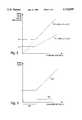
- FIG. 2 is a graph of threshold values, showing how thresholds which vary with quantizer step are selected
- FIG. 3 is a signal flow diagram showing a fast reduced coefficient DCT including the first three coefficients of the DCT;
- FIG. 4 is a block diagram showing selectively switching between a reduced coefficient DCT and a full DCT
- FIG. 5 is a graph of a threshold which varies with quantizer step size
- FIG. 6 is a block diagram of another apparatus for selectively switching between a reduced coefficient DCT and a full DCT, including quantization of the coefficients produced;
- FIG. 7 is a block diagram of yet another apparatus for selectively switching between a reduced coefficient DCT and a full DCT.
- FIG. 1 Some embodiments and variations disclosed herein are intended to be implemented in the form of software running on a personal computer (PC), configured substantially as shown in FIG. 1.
- PC personal computer
- FIG. 1 the specific hardware configuration is not a limitation of the present invention. Indeed, the invention could be embodied in a sequence of instructions executed by other types of general-purpose computers, parallel processing computers or embodied in special-purpose integrated circuits.
- the PC configuration of FIG. 1 illustrates general hardware parameters suitable for practicing the invention, without unduly complicating the detailed explanation thereof.
- the PC 101 includes a processing unit, generally a central processing unit (CPU) 103, memory 105, input/output (I/O) system 107 and mass storage 109.
- CPU central processing unit
- I/O input/output
- mass storage 109 mass storage
- the CPU 103 should preferably be of a type having an internal precision and register size of at least sixteen bits, such as the Intel X86 family or Motorola 680X0 devices.
- the minimum processing speed is not a critical parameter, but may be chosen by the skilled designer. Naturally, differences in processing speed will have a direct effect on the performance of different systems.
- processing unit could be an ALU, a digital signal processor or other suitable device.
- a suitable device is a processing unit capable of performing the functions described below, under software program control.
- I/O system 107 Data and digital signals of various kinds may be passed into or out of PC 101 through I/O system 107.
- I/O system 107 An extremely wide variety of devices may be included in I/O system 107.
- the devices of I/O system 107 allow digital image signals to be received into or transmitted out of PC 101.
- I/O system 107 may include a modem 108a for sending digital signals or receiving digital signals or data from remote devices and computers. Such digital signals could include digital image signals.
- Another possible I/O device is a frame grabber 108b, which could be used to introduce into PC 101 television or video images which have been converted to digital form.
- I/O system 107 may include such conventional I/O devices as a monitor 108c, keyboard 108d and printer (not shown), which may be desirable.
- the mass storage device 109 may be a hard disk, an optical disk, a CD-ROM or any permanent storage device having similar characteristics to the devices mentioned.
- Image signals are received into the PC 101 through one of the devices of I/O system 107. Once inside the PC 101, the image signals will have been converted to digital form. That is, they are digital image signals. In this embodiment, it is presumed that the digital image signals are to be either stored in a mass storage device 109 or transmitted to another location via one of the I/O devices of the I/O system 107.
- the PC 101 is part of a conferencing network in which images are to be exchanged, stored and displayed on a plurality of such machines.
- the above-described architecture of PC 101 is generic and need not be limited to personal computer embodiments.
- the architecture, illustrated in FIG. 1 is intended to represent all similar architectures including a processing unit, memory, I/O system, etc.
- the methods and apparatus next described relate primarily to a portion of the compression operation in accordance with ITU-T H.261, mentioned above, in which discrete cosine transforms are performed on image blocks.
- a method according to this first aspect of the invention is now described in connection with performing 2D 8 ⁇ 8-DCTs as shown in FIG. 3.
- a digital image signal is received into memory (FIG. 1, 105) and divided into input blocks 301 of 8 ⁇ 8 input signal sample values 303 which are subsequently transformed.
- the CPU of the PC is used to sum the values of the image samples contained in the first row 305 of the input block to form the sum S R1 .
- the values contained in the 8th row 307 of the input block are summed to form the value S R8 .
- the values contained in the 1st and 8th columns 309 and 311 of the input block are summed to form, respectively, values S C1 and S C8 .
- the three DCT coefficients C 00 , C 01 and C 10 are then formed from the following linear arithmetic combinations of the sums previously formed:
- the scaling factors k 00 , k 01 and k 10 are selected to provide whatever scaling may be desired.
- k 00 is realizable as a shift operation performed by the processing unit, for example, the CPU (FIG. 1, 103)
- k 01 and k 10 are realizable as integer multiplies and shifts performed by the processing unit, for example, the CPU (FIG. 1, 103).
- References herein to the CPU should be taken generally to include other processing units, as described above.
- the scaling 313 may be realized by using a table look up.
- a table of multiplied values is held in memory and a value to be multiplied 315a-315c is used by the CPU as an index into the table, in order to obtain a multiplied value 317a-317c.
- the scaling factors may be incorporated into quantizer tables that would normally be applied to the transform coefficients before outputting them.
- a reduced coefficient DCT is any approximation of a discrete cosine transform which computes from fewer than all of the input samples only a subset of coefficients including less than all of the coefficients required to completely represent a transformed input block.
- the coefficients computed for a reduced coefficient DCT will generally be the lower order coefficients. However, any desired set of coefficients may be computed. The remaining, coefficients are set to zero.
- the proper formation of the coefficients of a reduced coefficient DCT is achieved by the proper selection of sample values to use in a linear arithmetic combination to form the coefficients.
- the samples selected included all input sample signal values contained in the rows and columns at the edges of the input block (FIG. 3; 305, 307, 309 and 311).
- This selection of input signal sample values includes those sample values representative of the maximum positive and negative values of the basis functions represented by the three coefficients C 00 , C 01 and C 10 . Therefore, the sample values selected tend to provide the most noise-immune information from which to estimate the three coefficients desired.
- Some input blocks may not lend themselves to successful representation by a reduced coefficient DCT.
- Use of the above-described 3-coefficient DCT may lead to subjectively annoying artifacts, when indiscriminately applied.
- Some input blocks may require more than the first three DCT coefficients, in order to be represented accurately. Therefore, in accordance with a second aspect of the present invention, the above-described 3-coefficient DCT is applied only to input blocks which may be represented adequately by the first three coefficients, while other blocks are represented by greater numbers of coefficient values obtained using a conventional DCT method, the DCT method disclosed in the above-referenced U.S. patent application Ser. No. 08/125,590, or a reduced coefficient DCT producing more than three coefficients.
- the selective switching method described below may use any reduced coefficient DCT in place of the 3-coefficient DCT discussed below.
- higher coefficient reduced coefficient DCTs may be used.
- one method to switch selectively between the fast 3-coefficient DCT 401 and a full DCT 403 is first to apply the 3-coefficient DCT 401 to all input blocks 405.
- An inverse DCT 407 is then applied to the three coefficients 409 to produce a reconstructed block 411 including reconstructed signal sample values.
- An IDCT method such as one of those described in application Ser. No. 08/125,580 is particularly suitable in order to exploit the fact that all but three coefficients are zero.
- An error value indicative of differences between the original input block 405 and the reconstructed signal 411 is then accumulated 413.
- a wide variety of error measures are suitable, such as computations of the mean-squared-error, the mean absolute error, and the maximum error magnitude.
- the error value is smaller than a predetermined threshold (FIG. 2, T2), the fast 3-coefficient DCT is used, otherwise a conventional full DCT is applied to the input block.
- the result of this error value test 415 controls operation of the full DCT 403 and of the output 417.
- the predetermined threshold T2 501 is preferably selected as a function of the quantizer step-size q. It may be proportional to quantizer step-size over a range of coarse step sizes 503, but may be constant for fine quantization step sizes 505, as illustrated in FIG. 5.
- the IDCT may operate on quantized coefficients. That is, the 3-coefficient DCT 401 may include quantization to produce quantized coefficient 409. This is desirable, if the fast 3-coefficient DCT is embedded in a hybrid coder, such as shown in FIG. 6. As can be seen from FIG. 6, even when performing full DCTs, an inverse DCT 601 is applied to the quantized coefficients 603 in any case to compute the quantized prediction error e'. Therefore, computation of the inverse DCT for error checking does not require additional steps or apparatus.
- Another selective switching method suitable for input signals representative of moving video and used in connection with a hybrid coder is based on the root mean square (rms) value of the input signal sample values.
- rms root mean square
- the 3-coefficient DCT or other reduced coefficient DCT with selective switching may be performed as follows, in accordance with one embodiment of the invention:
- Thresholds T1 and T2 are selected as functions of quantizer step size used, as shown in FIG. 2.
- the four parameters a1, k1, a2 and k2 are adjusted to yield subjectively satisfying picture quality.
Abstract
Description
C.sub.00 =k.sub.00 (S.sub.R1 +S.sub.R8 +S.sub.C1 +S.sub.C8);
C.sub.01 =k.sub.01 (S.sub.C1 -S.sub.C8); and
C.sub.10 =k.sub.10 (S.sub.R1 -S.sub.R8),
Claims (15)
C.sub.00 =k.sub.00 ·(S.sub.RS +S.sub.RT +S.sub.CU +S.sub.CV),
C.sub.01 =k.sub.01 ·(S.sub.CU -S.sub.CV),
C.sub.10 =k.sub.10 ·(S.sub.RS -S.sub.RT),
Priority Applications (3)
| Application Number | Priority Date | Filing Date | Title |
|---|---|---|---|
| US08/332,535 US5712809A (en) | 1994-10-31 | 1994-10-31 | Method and apparatus for performing fast reduced coefficient discrete cosine transforms |
| PCT/US1995/012906 WO1996013780A2 (en) | 1994-10-31 | 1995-09-28 | Method and apparatus for performing fast reduced coefficient discrete cosine transforms |
| US08/940,191 US5822003A (en) | 1994-10-31 | 1997-09-29 | Method and apparatus for performing fast reduced coefficient discrete cosine transforms |
Applications Claiming Priority (1)
| Application Number | Priority Date | Filing Date | Title |
|---|---|---|---|
| US08/332,535 US5712809A (en) | 1994-10-31 | 1994-10-31 | Method and apparatus for performing fast reduced coefficient discrete cosine transforms |
Related Child Applications (1)
| Application Number | Title | Priority Date | Filing Date |
|---|---|---|---|
| US08/940,191 Division US5822003A (en) | 1994-10-31 | 1997-09-29 | Method and apparatus for performing fast reduced coefficient discrete cosine transforms |
Publications (1)
| Publication Number | Publication Date |
|---|---|
| US5712809A true US5712809A (en) | 1998-01-27 |
Family
ID=23298658
Family Applications (2)
| Application Number | Title | Priority Date | Filing Date |
|---|---|---|---|
| US08/332,535 Expired - Lifetime US5712809A (en) | 1994-10-31 | 1994-10-31 | Method and apparatus for performing fast reduced coefficient discrete cosine transforms |
| US08/940,191 Expired - Lifetime US5822003A (en) | 1994-10-31 | 1997-09-29 | Method and apparatus for performing fast reduced coefficient discrete cosine transforms |
Family Applications After (1)
| Application Number | Title | Priority Date | Filing Date |
|---|---|---|---|
| US08/940,191 Expired - Lifetime US5822003A (en) | 1994-10-31 | 1997-09-29 | Method and apparatus for performing fast reduced coefficient discrete cosine transforms |
Country Status (2)
| Country | Link |
|---|---|
| US (2) | US5712809A (en) |
| WO (1) | WO1996013780A2 (en) |
Cited By (12)
| Publication number | Priority date | Publication date | Assignee | Title |
|---|---|---|---|---|
| US5822003A (en) * | 1994-10-31 | 1998-10-13 | Girod; Bernd | Method and apparatus for performing fast reduced coefficient discrete cosine transforms |
| US6037985A (en) * | 1996-10-31 | 2000-03-14 | Texas Instruments Incorporated | Video compression |
| US6473534B1 (en) * | 1999-01-06 | 2002-10-29 | Hewlett-Packard Company | Multiplier-free implementation of DCT used in image and video processing and compression |
| US6498815B2 (en) * | 1998-02-13 | 2002-12-24 | Koninklijke Philips Electronics N.V. | Method and arrangement for video coding |
| US20040117418A1 (en) * | 2002-12-11 | 2004-06-17 | Leonardo Vainsencher | Forward discrete cosine transform engine |
| US20040125983A1 (en) * | 2000-02-14 | 2004-07-01 | Reed Alastair M. | Color adaptive watermarking |
| US6970179B1 (en) | 2000-05-12 | 2005-11-29 | International Business Machines Corporation | Method and apparatus for the scaling up of data |
| US7062098B1 (en) | 2000-05-12 | 2006-06-13 | International Business Machines Corporation | Method and apparatus for the scaling down of data |
| US20110289128A1 (en) * | 2010-05-24 | 2011-11-24 | Chih-Ta Star Sung | Method of performing discrete cosine transform |
| US20120177108A1 (en) * | 2011-01-10 | 2012-07-12 | Qualcomm Incorporated | 32-point transform for media data coding |
| US8423597B1 (en) | 2003-08-29 | 2013-04-16 | Nvidia Corporation | Method and system for adaptive matrix trimming in an inverse discrete cosine transform (IDCT) operation |
| US9798698B2 (en) | 2012-08-13 | 2017-10-24 | Nvidia Corporation | System and method for multi-color dilu preconditioner |
Families Citing this family (16)
| Publication number | Priority date | Publication date | Assignee | Title |
|---|---|---|---|---|
| US5986709A (en) * | 1996-11-18 | 1999-11-16 | Samsung Electronics Co., Ltd. | Adaptive lossy IDCT for multitasking environment |
| US5974184A (en) * | 1997-03-07 | 1999-10-26 | General Instrument Corporation | Intra-macroblock DC and AC coefficient prediction for interlaced digital video |
| US6160920A (en) * | 1998-09-15 | 2000-12-12 | Winbond Electronics Corp. | Cosine transforming and quantizing device, method of reducing multiplication operations in a video compressing apparatus |
| EP0990992A3 (en) * | 1998-09-28 | 2002-02-13 | Siemens Aktiengesellschaft | DCT/IDCT processor and data processing method |
| US6810082B1 (en) | 1999-12-17 | 2004-10-26 | Koninklijke Philips Electronics N.V. | Chroma based adaptive signal peaking |
| US6876703B2 (en) * | 2000-05-11 | 2005-04-05 | Ub Video Inc. | Method and apparatus for video coding |
| JP3684148B2 (en) * | 2000-10-20 | 2005-08-17 | キヤノン株式会社 | Image processing method and apparatus, and storage medium |
| US7007054B1 (en) | 2000-10-23 | 2006-02-28 | International Business Machines Corporation | Faster discrete cosine transforms using scaled terms |
| US6961473B1 (en) * | 2000-10-23 | 2005-11-01 | International Business Machines Corporation | Faster transforms using early aborts and precision refinements |
| US6766341B1 (en) | 2000-10-23 | 2004-07-20 | International Business Machines Corporation | Faster transforms using scaled terms |
| US7123655B2 (en) | 2001-08-09 | 2006-10-17 | Sharp Laboratories Of America, Inc. | Method for reduced bit-depth quantization |
| EP1442392A2 (en) * | 2001-10-29 | 2004-08-04 | Parthusceva Ltd. | Method and apparatus for performing spatial-to-frequency domain transform |
| US8595281B2 (en) | 2006-01-11 | 2013-11-26 | Qualcomm Incorporated | Transforms with common factors |
| US7262719B2 (en) * | 2006-01-30 | 2007-08-28 | International Business Machines Corporation | Fast data stream decoding using apriori information |
| US8849884B2 (en) | 2006-03-29 | 2014-09-30 | Qualcom Incorporate | Transform design with scaled and non-scaled interfaces |
| KR102250088B1 (en) | 2013-10-24 | 2021-05-10 | 삼성전자주식회사 | Method and Apparatus for decoding video stream |
Citations (7)
| Publication number | Priority date | Publication date | Assignee | Title |
|---|---|---|---|---|
| US4717962A (en) * | 1986-12-17 | 1988-01-05 | Kabushiki Kaisha Toshiba | Method for compressing and reconstructing a data representation of a picture |
| EP0429778A2 (en) * | 1989-11-27 | 1991-06-05 | Analogic Corporation | System and method of collecting and transmitting pictorial information |
| US5128757A (en) * | 1990-06-18 | 1992-07-07 | Zenith Electronics Corporation | Video transmission system using adaptive sub-band coding |
| US5301136A (en) * | 1992-03-17 | 1994-04-05 | Sun Microsystems, Inc. | Method and apparatus for fast implementation of inverse discrete cosine transform in a digital image processing system using low cost accumulators |
| US5365469A (en) * | 1990-10-31 | 1994-11-15 | International Business Machines Corporation | Fast fourier transform using balanced coefficients |
| WO1995022807A1 (en) * | 1994-02-22 | 1995-08-24 | Philippe Jullien | Multidimensional signal processing method and apparatus, and various uses thereof in image processing |
| US5539836A (en) * | 1991-12-20 | 1996-07-23 | Alaris Inc. | Method and apparatus for the realization of two-dimensional discrete cosine transform for an 8*8 image fragment |
Family Cites Families (2)
| Publication number | Priority date | Publication date | Assignee | Title |
|---|---|---|---|---|
| US5625714A (en) * | 1991-01-10 | 1997-04-29 | Olympus Optical Co., Ltd. | Image signal decoding device capable of removing block distortion with simple structure |
| US5712809A (en) * | 1994-10-31 | 1998-01-27 | Vivo Software, Inc. | Method and apparatus for performing fast reduced coefficient discrete cosine transforms |
-
1994
- 1994-10-31 US US08/332,535 patent/US5712809A/en not_active Expired - Lifetime
-
1995
- 1995-09-28 WO PCT/US1995/012906 patent/WO1996013780A2/en active Application Filing
-
1997
- 1997-09-29 US US08/940,191 patent/US5822003A/en not_active Expired - Lifetime
Patent Citations (7)
| Publication number | Priority date | Publication date | Assignee | Title |
|---|---|---|---|---|
| US4717962A (en) * | 1986-12-17 | 1988-01-05 | Kabushiki Kaisha Toshiba | Method for compressing and reconstructing a data representation of a picture |
| EP0429778A2 (en) * | 1989-11-27 | 1991-06-05 | Analogic Corporation | System and method of collecting and transmitting pictorial information |
| US5128757A (en) * | 1990-06-18 | 1992-07-07 | Zenith Electronics Corporation | Video transmission system using adaptive sub-band coding |
| US5365469A (en) * | 1990-10-31 | 1994-11-15 | International Business Machines Corporation | Fast fourier transform using balanced coefficients |
| US5539836A (en) * | 1991-12-20 | 1996-07-23 | Alaris Inc. | Method and apparatus for the realization of two-dimensional discrete cosine transform for an 8*8 image fragment |
| US5301136A (en) * | 1992-03-17 | 1994-04-05 | Sun Microsystems, Inc. | Method and apparatus for fast implementation of inverse discrete cosine transform in a digital image processing system using low cost accumulators |
| WO1995022807A1 (en) * | 1994-02-22 | 1995-08-24 | Philippe Jullien | Multidimensional signal processing method and apparatus, and various uses thereof in image processing |
Non-Patent Citations (12)
| Title |
|---|
| "3-to-1 Scaling in the DCT Domain", Research Disclosure, No. 345, 1 Jan. 1993, p. 77. |
| "Applying Digital Signal Processing", Electronics World + Wireless World, vol. 97, No.1677, Aug. 1992 Sutton, Surrey, GB pp. 669-672. |
| 3 to 1 Scaling in the DCT Domain , Research Disclosure, No. 345, 1 Jan. 1993, p. 77. * |
| Applying Digital Signal Processing , Electronics World Wireless World, vol. 97, No.1677, Aug. 1992 Sutton, Surrey, GB pp. 669 672. * |
| Cham, Wai kuen, et al., A 2 D Integer Cosine Transform Chip Set and its Application , IEEE Transactions on Consumer Electronics, vol. 38, No. 2, May 1992, New York, US, pp. 43 47. * |
| Cham, Wai-kuen, et al., "A 2-D Integer Cosine Transform Chip Set and its Application", IEEE Transactions on Consumer Electronics, vol. 38, No. 2, May 1992, New York, US, pp. 43-47. |
| DeNatale, Francesco G.B., et al. "Adaptive DCT for Image-Data Compression", European Transactions on Telecomm. and Related Technologies, vol. 3, No. 4, Jul./Aug. 1992,Milano, IT, pp. 49-56. |
| DeNatale, Francesco G.B., et al. Adaptive DCT for Image Data Compression , European Transactions on Telecomm. and Related Technologies, vol. 3, No. 4, Jul./Aug. 1992,Milano, IT, pp. 49 56. * |
| Gertner, I., "A New Efficient Algorithm to Compute the Two-Dimensional Discrete Fourier Transform", IEEE Trans. on Acoustics, Speech, and Signal Processing, vol. 36, No. 7, Jul. 1988, pp. 1036-1050. |
| Gertner, I., A New Efficient Algorithm to Compute the Two Dimensional Discrete Fourier Transform , IEEE Trans. on Acoustics, Speech, and Signal Processing, vol. 36, No. 7, Jul. 1988, pp. 1036 1050. * |
| Y. Chan and W. Siu, Short Communication, An Approach to Subband DCT Image Coding, Journal of Visual Communication and Image Representation 5(1), 1994, 95 106. * |
| Y. Chan and W. Siu, Short Communication, An Approach to Subband DCT Image Coding, Journal of Visual Communication and Image Representation 5(1), 1994, 95-106. |
Cited By (19)
| Publication number | Priority date | Publication date | Assignee | Title |
|---|---|---|---|---|
| US5822003A (en) * | 1994-10-31 | 1998-10-13 | Girod; Bernd | Method and apparatus for performing fast reduced coefficient discrete cosine transforms |
| US6037985A (en) * | 1996-10-31 | 2000-03-14 | Texas Instruments Incorporated | Video compression |
| US6498815B2 (en) * | 1998-02-13 | 2002-12-24 | Koninklijke Philips Electronics N.V. | Method and arrangement for video coding |
| US6473534B1 (en) * | 1999-01-06 | 2002-10-29 | Hewlett-Packard Company | Multiplier-free implementation of DCT used in image and video processing and compression |
| US20040125983A1 (en) * | 2000-02-14 | 2004-07-01 | Reed Alastair M. | Color adaptive watermarking |
| US7391880B2 (en) * | 2000-02-14 | 2008-06-24 | Digimarc Corporation | Color adaptive watermarking |
| US7903889B2 (en) | 2000-05-12 | 2011-03-08 | International Business Machines Corporation | System and computer readable medium for the scaling down of data |
| US6970179B1 (en) | 2000-05-12 | 2005-11-29 | International Business Machines Corporation | Method and apparatus for the scaling up of data |
| US7062098B1 (en) | 2000-05-12 | 2006-06-13 | International Business Machines Corporation | Method and apparatus for the scaling down of data |
| US20080212885A1 (en) * | 2000-05-12 | 2008-09-04 | International Business Machines Corporation | Scaling down of data |
| US20090060358A1 (en) * | 2000-05-12 | 2009-03-05 | International Business Machines Corporation | System and computer readable medium for the scaling down of data |
| US7720310B2 (en) | 2000-05-12 | 2010-05-18 | International Business Machines Corporation | Scaling down of data |
| US20040117418A1 (en) * | 2002-12-11 | 2004-06-17 | Leonardo Vainsencher | Forward discrete cosine transform engine |
| US7792891B2 (en) * | 2002-12-11 | 2010-09-07 | Nvidia Corporation | Forward discrete cosine transform engine |
| US8423597B1 (en) | 2003-08-29 | 2013-04-16 | Nvidia Corporation | Method and system for adaptive matrix trimming in an inverse discrete cosine transform (IDCT) operation |
| US20110289128A1 (en) * | 2010-05-24 | 2011-11-24 | Chih-Ta Star Sung | Method of performing discrete cosine transform |
| US20120177108A1 (en) * | 2011-01-10 | 2012-07-12 | Qualcomm Incorporated | 32-point transform for media data coding |
| US9824066B2 (en) * | 2011-01-10 | 2017-11-21 | Qualcomm Incorporated | 32-point transform for media data coding |
| US9798698B2 (en) | 2012-08-13 | 2017-10-24 | Nvidia Corporation | System and method for multi-color dilu preconditioner |
Also Published As
| Publication number | Publication date |
|---|---|
| WO1996013780A3 (en) | 1996-11-28 |
| WO1996013780A2 (en) | 1996-05-09 |
| US5822003A (en) | 1998-10-13 |
Similar Documents
| Publication | Publication Date | Title |
|---|---|---|
| US5712809A (en) | Method and apparatus for performing fast reduced coefficient discrete cosine transforms | |
| US5917954A (en) | Image signal coder operating at reduced spatial resolution | |
| Wallace | The JPEG still picture compression standard | |
| US6167092A (en) | Method and device for variable complexity decoding of motion-compensated block-based compressed digital video | |
| US5881176A (en) | Compression and decompression with wavelet style and binary style including quantization by device-dependent parser | |
| US5966465A (en) | Compression/decompression using reversible embedded wavelets | |
| US6757437B1 (en) | Compression/decompression using reversible embedded wavelets | |
| US7194128B1 (en) | Data compression using principal components transformation | |
| EP0859520B1 (en) | Video signal coding systems and processes using adaptive quantization | |
| US5371611A (en) | Method for and system of decoding compressed continuous-tone digital image data | |
| Monro et al. | Fractal image compression without searching | |
| US6385242B1 (en) | Method and apparatus for inverse quantization of MPEG-4 video | |
| KR100944928B1 (en) | Apparatus and method for encoding and computing a discrete cosine transform using a butterfly processor | |
| KR100510756B1 (en) | Image decoding apparatus and method and image reproducing apparatus | |
| US6597811B1 (en) | Method and device for image digitized data compression and decompression | |
| US5689592A (en) | Parallel processing of digital signals in a single arithmetic/logic unit | |
| US6850566B2 (en) | Implementation of quantization for SIMD architecture | |
| US7046852B2 (en) | Fast image decompression via look up table | |
| US20020173952A1 (en) | Coding | |
| US6658161B1 (en) | Signal-processing method and device therefore | |
| US7570818B2 (en) | Method for deblocking and transcoding a media stream | |
| Ahlgren et al. | Compression of digitized images for transmission and storage applications | |
| Sandy et al. | Analysis of video compression algorithms using DCT, DWT and FFT | |
| Mietens et al. | New scalable DCT computation for resource-constrained systems | |
| Mietens et al. | New DCT computation algorithm for video quality scaling |
Legal Events
| Date | Code | Title | Description |
|---|---|---|---|
| AS | Assignment |
Owner name: VIVO SOFTWARE, INC., MASSACHUSETTS Free format text: ASSIGNMENT OF ASSIGNORS INTEREST;ASSIGNORS:GIROD, BERND;ERICSSON, STAFFAN;REEL/FRAME:007292/0506 Effective date: 19941122 |
|
| FEPP | Fee payment procedure |
Free format text: PAYOR NUMBER ASSIGNED (ORIGINAL EVENT CODE: ASPN); ENTITY STATUS OF PATENT OWNER: LARGE ENTITY |
|
| STCF | Information on status: patent grant |
Free format text: PATENTED CASE |
|
| AS | Assignment |
Owner name: REALNETWORKS, INC., WASHINGTON Free format text: ASSIGNMENT OF ASSIGNORS INTEREST;ASSIGNOR:VIVO SOFTWARE, INC.;REEL/FRAME:009257/0385 Effective date: 19980324 |
|
| FEPP | Fee payment procedure |
Free format text: PAYER NUMBER DE-ASSIGNED (ORIGINAL EVENT CODE: RMPN); ENTITY STATUS OF PATENT OWNER: LARGE ENTITY Free format text: PAYOR NUMBER ASSIGNED (ORIGINAL EVENT CODE: ASPN); ENTITY STATUS OF PATENT OWNER: LARGE ENTITY |
|
| FEPP | Fee payment procedure |
Free format text: PAYER NUMBER DE-ASSIGNED (ORIGINAL EVENT CODE: RMPN); ENTITY STATUS OF PATENT OWNER: LARGE ENTITY Free format text: PAYOR NUMBER ASSIGNED (ORIGINAL EVENT CODE: ASPN); ENTITY STATUS OF PATENT OWNER: LARGE ENTITY |
|
| FEPP | Fee payment procedure |
Free format text: PAT HLDR NO LONGER CLAIMS SMALL ENT STAT AS SMALL BUSINESS (ORIGINAL EVENT CODE: LSM2); ENTITY STATUS OF PATENT OWNER: LARGE ENTITY |
|
| FPAY | Fee payment |
Year of fee payment: 4 |
|
| FPAY | Fee payment |
Year of fee payment: 8 |
|
| FPAY | Fee payment |
Year of fee payment: 12 |
|
| AS | Assignment |
Owner name: REALNETWORKS, INC., WASHINGTON Free format text: ASSIGNMENT OF ASSIGNORS INTEREST;ASSIGNOR:RN ACQUISITION CORPORATION;REEL/FRAME:027905/0525 Effective date: 20120319 Owner name: RN ACQUISITION CORPORATION, WASHINGTON Free format text: ASSIGNMENT OF ASSIGNORS INTEREST;ASSIGNOR:VIVO SOFTWARE, INC.;REEL/FRAME:027905/0534 Effective date: 19980324 |
|
| AS | Assignment |
Owner name: INTEL CORPORATION, CALIFORNIA Free format text: ASSIGNMENT OF ASSIGNORS INTEREST;ASSIGNOR:REALNETWORKS, INC.;REEL/FRAME:028752/0734 Effective date: 20120419 |
|
| FEPP | Fee payment procedure |
Free format text: PAYER NUMBER DE-ASSIGNED (ORIGINAL EVENT CODE: RMPN); ENTITY STATUS OF PATENT OWNER: LARGE ENTITY Free format text: PAYOR NUMBER ASSIGNED (ORIGINAL EVENT CODE: ASPN); ENTITY STATUS OF PATENT OWNER: LARGE ENTITY |