US5707030A - Waste-carrier trolley with a base in the form of a tray, more particularly for gardening - Google Patents
Waste-carrier trolley with a base in the form of a tray, more particularly for gardening Download PDFInfo
- Publication number
- US5707030A US5707030A US08/731,051 US73105196A US5707030A US 5707030 A US5707030 A US 5707030A US 73105196 A US73105196 A US 73105196A US 5707030 A US5707030 A US 5707030A
- Authority
- US
- United States
- Prior art keywords
- trolley
- tray
- snap
- supporting
- bag
- Prior art date
- Legal status (The legal status is an assumption and is not a legal conclusion. Google has not performed a legal analysis and makes no representation as to the accuracy of the status listed.)
- Expired - Fee Related
Links
Images


Classifications
-
- B—PERFORMING OPERATIONS; TRANSPORTING
- B62—LAND VEHICLES FOR TRAVELLING OTHERWISE THAN ON RAILS
- B62B—HAND-PROPELLED VEHICLES, e.g. HAND CARTS OR PERAMBULATORS; SLEDGES
- B62B1/00—Hand carts having only one axis carrying one or more transport wheels; Equipment therefor
- B62B1/26—Hand carts having only one axis carrying one or more transport wheels; Equipment therefor characterised by supports specially adapted to objects of definite shape
-
- B—PERFORMING OPERATIONS; TRANSPORTING
- B62—LAND VEHICLES FOR TRAVELLING OTHERWISE THAN ON RAILS
- B62B—HAND-PROPELLED VEHICLES, e.g. HAND CARTS OR PERAMBULATORS; SLEDGES
- B62B2202/00—Indexing codes relating to type or characteristics of transported articles
- B62B2202/22—Flexible bags, e.g. for rubbish
Definitions
- the present invention relates to a waste-carrier trolley with the base in the form of a tray, more particularly for gardening.
- a trolley for the collection of waste more particularly that produced during work in the garden, which comprises a pair of sides in a plastic material provided with a through hole for the insertion and the separable snap-locking of a shaft for supporting a pair of wheels and housings for inserting and separably snap-locking respective ends of tubular metal elements bent into a U shape, upper and lower, which form a manoeuvring handle and a base for resting the trolley on the ground respectively.
- a ring is also provided for the attachment of a collection bag, which is mechanically coupled to said upper tubular element at a height which varies in relation to the lower tubular element, which in turn supports a metal basket for supporting the base of the bag.
- a rotating lid can finally be connected to the aforementioned attachment ring to cover the bag when required.
- the object of the present invention is that of improving the aforementioned trolley, making resting of the trolley on the ground and support of the base of the bag simpler, less expensive and more functional.
- this object is achieved with a trolley which is distinguished from that of the aforementioned European Patent Application due to the fact that the lower tubular metal element with related basket for supporting the bag is replaced by a tray in a plastic material fitted with projections which can be inserted and separably snap-locked in said housings of the sides of the trolley and means for separably snap-locking to the shaft supporting the wheels.
- a tray in a plastic material with the dual function of a support base of the trolley and support of the bag eliminates the costly use of a lower tubular metal element bent into a U shape and a basket, also in metal, complicated to machine, and hence definitively reduces the cost of the trolley, and on the other hand ensures a better support of the base of the bag and the collection of any liquids and other materials discharged from the bag. It is easy to wash and, if necessary, can be detached and re-attached as required.
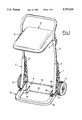
- FIG. 1 shows in perspective a trolley according to the invention with the lid in the closure position
- FIG. 2 shows said trolley again in perspective but with the lid open
- FIG. 3 shows the upper part of the trolley with the lid open in an enlarged lateral view
- FIG. 4 shows the base tray and one of the two sides of said trolley in an exploded perspective
- FIG. 5 shows a sectioned and enlarged detail of the attachment of the tray to one of said sides
- FIG. 6 shows the same detail sectioned along line VI--VI of FIG. 5;
- FIG. 7 shows in perspective the enlarged detail of the hooking of the tray to the shaft for supporting the wheels.
- a waste-carrier trolley comprises a pair of lateral sides 1, made in a plastic material, each provided with an upper housing 2 wherein a respective end of a tubular metal element 2, U-shaped and partially bent backwards to form a handle for manoeuvring the trolley, is inserted and separably snap-locked.
- Each side 1 is also provided with a lower housing 4, wherein a respective rear tubular projection 5 (FIG. 4) of a tray in a plastic material 6 which acts as a base for supporting the trolley, is inserted and separably snap-locked.
- Each side 1 is also provided with a through hole 7 (FIG. 4) wherein a metal shaft 8, used to support rotatingly a pair of wheels 9, is inserted and separably snap-locked.
- a ring 10 suitable for the separable attachment of the top of a collection bag (not shown in the drawings), is coupled to the tubular metal element 3 by means of a pair of sleeves 11, which may be made to slide along two vertical sections of the tubular element itself in order to vary the height of the top of the bag from the ground.
- sleeves 11 are fitted with suitable means for their locking at the chosen height, for example of the lever type described in the European Patent Application referred above.
- Each of the sleeves 11 is also provided, on the inner wall, with a pin (not shown in the drawings but also of the type described in the aforementioned European Patent Application), whereon a tiltable lid 12 is separably engaged.
- a tiltable lid 12 In the closure position of FIG. 1 the lid 12 rests horizontally on the ring 10 for the upper covering of the bag, using for this purpose a pair of internal ribs 13 shown in FIG. 3, while in the opening position of FIG. 2 the lid 12 is arranged and remains in a vertical position, using for this purpose an appropriate arrangement of the centre of gravity and a pair of ribs 14, also shown in FIG. 3, which butt against the aforementioned vertical sections of the tubular element 3.
- the base of the bag attached to the ring 10 is supported by the aforementioned tray 6, whose constructional details, including its means of hooking to the sides and to the shaft of the wheels, can be seen in FIGS. 4-7.
- the tray 6 consists of a hollow body with a continuous base and raised front and side edge 15, internal reinforcement ribs 16 and rear wall 17 hooked separably to the shaft 8 of the wheels 9 thanks to an upper turned-up part 18 and to lower turned-up brackets 19 provided at the small windows 20 formed on the top of the rear wall 17 (FIGS. 1, 2, 4 and 7).
- the tray 6 is attached to the sides 1, as mentioned previously, by the insertion and snap-locking of the tubular projections 5, which extend at the rear from the lateral parts of the edge 15 of the tray, in the lower housings 4 of the sides.
- the snap-locking is obtained by inserting a tooth 21 projecting transversely from an elastic tab 22 integral with the housing 4 into a radial hole 23 of the tubular projection 5.
Abstract
The trolley comprises a pair of sides in a plastic material provided with a through hole for inserting and separably snap-locking a support shaft for a pair of wheels and upper housings for inserting and separably snap-locking respective ends of a tubular metal element, bent into a U shape, which forms a handle for manoeuvring the trolley. The tubular element is mechanically restrained at a variable height to an attachment ring for a collection bag. The trolley also comprises a tray in a plastic material designed to act as a base for supporting the trolley on the ground and as an element for supporting the base of the bag. The tray is fitted with projections which can be inserted and separably snap-locked in lower housings of the sides of the trolley and means for its separable snap-hooking to the shape for supporting the wheels.
Description
The present invention relates to a waste-carrier trolley with the base in the form of a tray, more particularly for gardening.
In the European Patent Application no. 0626300, in the name of the same Applicant, a description is given of a trolley for the collection of waste, more particularly that produced during work in the garden, which comprises a pair of sides in a plastic material provided with a through hole for the insertion and the separable snap-locking of a shaft for supporting a pair of wheels and housings for inserting and separably snap-locking respective ends of tubular metal elements bent into a U shape, upper and lower, which form a manoeuvring handle and a base for resting the trolley on the ground respectively. A ring is also provided for the attachment of a collection bag, which is mechanically coupled to said upper tubular element at a height which varies in relation to the lower tubular element, which in turn supports a metal basket for supporting the base of the bag. A rotating lid can finally be connected to the aforementioned attachment ring to cover the bag when required.
The object of the present invention is that of improving the aforementioned trolley, making resting of the trolley on the ground and support of the base of the bag simpler, less expensive and more functional.
In accordance with the invention this object is achieved with a trolley which is distinguished from that of the aforementioned European Patent Application due to the fact that the lower tubular metal element with related basket for supporting the bag is replaced by a tray in a plastic material fitted with projections which can be inserted and separably snap-locked in said housings of the sides of the trolley and means for separably snap-locking to the shaft supporting the wheels.
The use of a tray in a plastic material with the dual function of a support base of the trolley and support of the bag eliminates the costly use of a lower tubular metal element bent into a U shape and a basket, also in metal, complicated to machine, and hence definitively reduces the cost of the trolley, and on the other hand ensures a better support of the base of the bag and the collection of any liquids and other materials discharged from the bag. It is easy to wash and, if necessary, can be detached and re-attached as required.
These and other features of the present invention will be made clearer from the following detailed description of one of its embodiments, illustrated by way of a non-limiting example in the accompanying drawings, in which:
FIG. 1 shows in perspective a trolley according to the invention with the lid in the closure position;
FIG. 2 shows said trolley again in perspective but with the lid open;
FIG. 3 shows the upper part of the trolley with the lid open in an enlarged lateral view;
FIG. 4 shows the base tray and one of the two sides of said trolley in an exploded perspective;
FIG. 5 shows a sectioned and enlarged detail of the attachment of the tray to one of said sides;
FIG. 6 shows the same detail sectioned along line VI--VI of FIG. 5;
FIG. 7 shows in perspective the enlarged detail of the hooking of the tray to the shaft for supporting the wheels.
With reference to FIGS. 1 and 2, a waste-carrier trolley according to the invention comprises a pair of lateral sides 1, made in a plastic material, each provided with an upper housing 2 wherein a respective end of a tubular metal element 2, U-shaped and partially bent backwards to form a handle for manoeuvring the trolley, is inserted and separably snap-locked.
Each side 1 is also provided with a lower housing 4, wherein a respective rear tubular projection 5 (FIG. 4) of a tray in a plastic material 6 which acts as a base for supporting the trolley, is inserted and separably snap-locked.
Each side 1 is also provided with a through hole 7 (FIG. 4) wherein a metal shaft 8, used to support rotatingly a pair of wheels 9, is inserted and separably snap-locked.
A ring 10, suitable for the separable attachment of the top of a collection bag (not shown in the drawings), is coupled to the tubular metal element 3 by means of a pair of sleeves 11, which may be made to slide along two vertical sections of the tubular element itself in order to vary the height of the top of the bag from the ground. Each of said sleeves is fitted with suitable means for their locking at the chosen height, for example of the lever type described in the European Patent Application referred above.
Each of the sleeves 11 is also provided, on the inner wall, with a pin (not shown in the drawings but also of the type described in the aforementioned European Patent Application), whereon a tiltable lid 12 is separably engaged. In the closure position of FIG. 1 the lid 12 rests horizontally on the ring 10 for the upper covering of the bag, using for this purpose a pair of internal ribs 13 shown in FIG. 3, while in the opening position of FIG. 2 the lid 12 is arranged and remains in a vertical position, using for this purpose an appropriate arrangement of the centre of gravity and a pair of ribs 14, also shown in FIG. 3, which butt against the aforementioned vertical sections of the tubular element 3.
The base of the bag attached to the ring 10 is supported by the aforementioned tray 6, whose constructional details, including its means of hooking to the sides and to the shaft of the wheels, can be seen in FIGS. 4-7.
The tray 6 consists of a hollow body with a continuous base and raised front and side edge 15, internal reinforcement ribs 16 and rear wall 17 hooked separably to the shaft 8 of the wheels 9 thanks to an upper turned-up part 18 and to lower turned-up brackets 19 provided at the small windows 20 formed on the top of the rear wall 17 (FIGS. 1, 2, 4 and 7).
The tray 6 is attached to the sides 1, as mentioned previously, by the insertion and snap-locking of the tubular projections 5, which extend at the rear from the lateral parts of the edge 15 of the tray, in the lower housings 4 of the sides. As shown in FIGS. 5 and 6, the snap-locking is obtained by inserting a tooth 21 projecting transversely from an elastic tab 22 integral with the housing 4 into a radial hole 23 of the tubular projection 5.
Claims (7)
1. Waste-carrier trolley, more particularly for gardening, comprising a pair of sides in a plastic material provided with a through hole for the insertion and separable snap-locking of a shaft for supporting a pair of wheels and upper housings for the insertion and separable snap-locking of respective ends of a tubular metal element bent into a U shape, which forms a handle for manoeuvring the trolley and whereto a ring for the attachment of a collection bag is coupled mechanically at a variable height, characterised in that it also comprises a tray in a plastic material designed to act as a base for supporting the trolley on the ground and as an element for supporting the base of the bag, said tray being provided with projections which can be inserted and separably snap-locked in lower housings of the sides of the trolley and means for its separable snap-hooking to the shaft for supporting the wheels.
2. Trolley according to claim 1, characterised in that said tray consists of a hollow body with a continuous base and raised front and side edge and rear wall.
3. Trolley according to claim 1, characterised in that said lower housings of the sides are each provided with a flexible tab provided with a transverse tooth which can be inserted in a radial hole of a respective tubular projection of the tray for the snap-locking of the tubular projection in the respective housing.
4. Trolley according to claim 2, characterised in that said means for the separable snap-hooking of the tray to the shaft supporting the wheels consist of an upper turned-up part of said rear wall and of underlying lower brackets turned upwards.
5. Trolley according to claim 1, characterised in that it comprises a rotating lid connected to said attachment ring to cover the bag when required.
6. Trolley according to claim 5, characterised in that said lid is provided with internal ribs for its resting on said attachment ring when it is arranged in a position of closure of the bag.
7. Trolley according to claim 5, characterised in that said lid is provided with further ribs which can butt against vertical sections of said tubular element to maintain said lid in a position of opening of the bag.
Applications Claiming Priority (2)
| Application Number | Priority Date | Filing Date | Title |
|---|---|---|---|
| IT1995MI000699U IT237216Y1 (en) | 1995-10-13 | 1995-10-13 | TRAY-BASED WASTE TROLLEY, PARTICULARLY FOR GARDENING |
| ITMI950699U | 1995-10-13 |
Publications (1)
| Publication Number | Publication Date |
|---|---|
| US5707030A true US5707030A (en) | 1998-01-13 |
Family
ID=11371231
Family Applications (1)
| Application Number | Title | Priority Date | Filing Date |
|---|---|---|---|
| US08/731,051 Expired - Fee Related US5707030A (en) | 1995-10-13 | 1996-10-09 | Waste-carrier trolley with a base in the form of a tray, more particularly for gardening |
Country Status (6)
| Country | Link |
|---|---|
| US (1) | US5707030A (en) |
| EP (1) | EP0768228B1 (en) |
| AT (1) | ATE183162T1 (en) |
| DE (1) | DE69603679T2 (en) |
| ES (1) | ES2135163T3 (en) |
| IT (1) | IT237216Y1 (en) |
Cited By (6)
| Publication number | Priority date | Publication date | Assignee | Title |
|---|---|---|---|---|
| US7063339B2 (en) * | 2002-02-01 | 2006-06-20 | Jarko Paul R | Load dolly |
| US20060289544A1 (en) * | 2005-06-23 | 2006-12-28 | Kerekes John L Jr | Bag holder |
| US20080309038A1 (en) * | 2007-06-14 | 2008-12-18 | James Gilligan | Trash bag holder and transporter |
| US20110016625A1 (en) * | 2007-01-31 | 2011-01-27 | Garry Robin Marty | Mixing valve including a molded waterway assembly |
| US20140265190A1 (en) * | 2013-03-15 | 2014-09-18 | Aaron Beaver | Tote transport |
| USD878908S1 (en) * | 2017-07-18 | 2020-03-24 | Dess Langdon | Garden hose reel |
Citations (3)
| Publication number | Priority date | Publication date | Assignee | Title |
|---|---|---|---|---|
| US4452468A (en) * | 1982-09-08 | 1984-06-05 | O. Ames Co. | Cart with molded bag supporting structures |
| WO1992014638A1 (en) * | 1991-02-25 | 1992-09-03 | Elon Ltd New Products Research And Trading Company | Folding shopping carriage |
| EP0626300A1 (en) * | 1993-05-25 | 1994-11-30 | Claber S.P.A. | Cart for the collection of rubbish in general and its transportation over uneven terrain, particularly suitable for use in gardening |
-
1995
- 1995-10-13 IT IT1995MI000699U patent/IT237216Y1/en active IP Right Grant
-
1996
- 1996-10-08 AT AT96202797T patent/ATE183162T1/en not_active IP Right Cessation
- 1996-10-08 EP EP96202797A patent/EP0768228B1/en not_active Expired - Lifetime
- 1996-10-08 DE DE69603679T patent/DE69603679T2/en not_active Expired - Fee Related
- 1996-10-08 ES ES96202797T patent/ES2135163T3/en not_active Expired - Lifetime
- 1996-10-09 US US08/731,051 patent/US5707030A/en not_active Expired - Fee Related
Patent Citations (3)
| Publication number | Priority date | Publication date | Assignee | Title |
|---|---|---|---|---|
| US4452468A (en) * | 1982-09-08 | 1984-06-05 | O. Ames Co. | Cart with molded bag supporting structures |
| WO1992014638A1 (en) * | 1991-02-25 | 1992-09-03 | Elon Ltd New Products Research And Trading Company | Folding shopping carriage |
| EP0626300A1 (en) * | 1993-05-25 | 1994-11-30 | Claber S.P.A. | Cart for the collection of rubbish in general and its transportation over uneven terrain, particularly suitable for use in gardening |
Cited By (11)
| Publication number | Priority date | Publication date | Assignee | Title |
|---|---|---|---|---|
| US7063339B2 (en) * | 2002-02-01 | 2006-06-20 | Jarko Paul R | Load dolly |
| US20060289544A1 (en) * | 2005-06-23 | 2006-12-28 | Kerekes John L Jr | Bag holder |
| US7604143B2 (en) | 2005-06-23 | 2009-10-20 | Kerekes Jr John L | Bag holder |
| US20100038367A1 (en) * | 2005-06-23 | 2010-02-18 | Kerekes Jr John L | Bag holder |
| US20110016625A1 (en) * | 2007-01-31 | 2011-01-27 | Garry Robin Marty | Mixing valve including a molded waterway assembly |
| US20080309038A1 (en) * | 2007-06-14 | 2008-12-18 | James Gilligan | Trash bag holder and transporter |
| US20140265190A1 (en) * | 2013-03-15 | 2014-09-18 | Aaron Beaver | Tote transport |
| US9150234B2 (en) * | 2013-03-15 | 2015-10-06 | San Jamar, Inc. | Tote transport |
| US20160031467A1 (en) * | 2013-03-15 | 2016-02-04 | San Jamar, Inc. | Tote Transport |
| US9580096B2 (en) * | 2013-03-15 | 2017-02-28 | San Jamar, Inc. | Tote transport |
| USD878908S1 (en) * | 2017-07-18 | 2020-03-24 | Dess Langdon | Garden hose reel |
Also Published As
| Publication number | Publication date |
|---|---|
| ITMI950699V0 (en) | 1995-10-13 |
| DE69603679T2 (en) | 2000-01-05 |
| ES2135163T3 (en) | 1999-10-16 |
| ITMI950699U1 (en) | 1997-04-13 |
| ATE183162T1 (en) | 1999-08-15 |
| EP0768228B1 (en) | 1999-08-11 |
| DE69603679D1 (en) | 1999-09-16 |
| IT237216Y1 (en) | 2000-09-05 |
| EP0768228A1 (en) | 1997-04-16 |
Similar Documents
| Publication | Publication Date | Title |
|---|---|---|
| US7530578B2 (en) | Step-on receptacle with tip prevention | |
| US5794649A (en) | Portable hose cart assembly | |
| US4341393A (en) | Hand cart | |
| EP1030811B1 (en) | Device for supporting a lid in an approximately vertical position | |
| US4015406A (en) | Lawnmower bagging apparatus | |
| CA1308137C (en) | Wheeled hand cart for wet/dry utility vacuum cleaner | |
| US20100147865A1 (en) | Step trash can having integrated base and base liner | |
| US7494022B2 (en) | Bag retention apparatus and method | |
| US5707030A (en) | Waste-carrier trolley with a base in the form of a tray, more particularly for gardening | |
| JPH0664674A (en) | Clothes basket | |
| FR2580163A1 (en) | COFFEE MACHINE AND COFFEE POT | |
| US5425469A (en) | Liner concealing trash receptacle | |
| US20040250711A1 (en) | Lid for a refuse container | |
| MXPA04004776A (en) | Paint roller grid. | |
| US6119282A (en) | Toilet drip and splash guard | |
| US5033258A (en) | Power lawn mower assembly and system for supporting bag thereon | |
| KR200434937Y1 (en) | Cart with supporting pole of garbage bag and gutter | |
| US5845473A (en) | Material collection bag | |
| FR2718435A1 (en) | Composting bin with bottom drain valve | |
| US5655233A (en) | Toilet dome | |
| GB2427174A (en) | Gardening aid | |
| EP0626300B1 (en) | Cart for the collection of rubbish in general and its transportation over uneven terrain, particularly suitable for use in gardening | |
| FR2625643A1 (en) | FRAME FOR DEBRIS COLLECTOR AND COLLECTION ASSEMBLY | |
| AU5713294A (en) | Vapour emission devices for refuse containers | |
| GB1593982A (en) | Chairs for infants |
Legal Events
| Date | Code | Title | Description |
|---|---|---|---|
| AS | Assignment |
Owner name: CLABER S.P.A., ITALY Free format text: ASSIGNMENT OF ASSIGNORS INTEREST;ASSIGNOR:ROMAN, GIANFRANCO;REEL/FRAME:008235/0425 Effective date: 19961001 |
|
| REMI | Maintenance fee reminder mailed | ||
| LAPS | Lapse for failure to pay maintenance fees | ||
| STCH | Information on status: patent discontinuation |
Free format text: PATENT EXPIRED DUE TO NONPAYMENT OF MAINTENANCE FEES UNDER 37 CFR 1.362 |
|
| FP | Lapsed due to failure to pay maintenance fee |
Effective date: 20020113 |