US5697553A - Streaked spray nozzle for enhanced air/fuel mixing - Google Patents
Streaked spray nozzle for enhanced air/fuel mixing Download PDFInfo
- Publication number
- US5697553A US5697553A US08/397,799 US39779995A US5697553A US 5697553 A US5697553 A US 5697553A US 39779995 A US39779995 A US 39779995A US 5697553 A US5697553 A US 5697553A
- Authority
- US
- United States
- Prior art keywords
- swirl chamber
- swirl
- discharge orifice
- conical
- spray
- Prior art date
- Legal status (The legal status is an assumption and is not a legal conclusion. Google has not performed a legal analysis and makes no representation as to the accuracy of the status listed.)
- Expired - Fee Related
Links
Images


Classifications
-
- B—PERFORMING OPERATIONS; TRANSPORTING
- B05—SPRAYING OR ATOMISING IN GENERAL; APPLYING FLUENT MATERIALS TO SURFACES, IN GENERAL
- B05B—SPRAYING APPARATUS; ATOMISING APPARATUS; NOZZLES
- B05B7/00—Spraying apparatus for discharge of liquids or other fluent materials from two or more sources, e.g. of liquid and air, of powder and gas
- B05B7/02—Spray pistols; Apparatus for discharge
- B05B7/06—Spray pistols; Apparatus for discharge with at least one outlet orifice surrounding another approximately in the same plane
- B05B7/062—Spray pistols; Apparatus for discharge with at least one outlet orifice surrounding another approximately in the same plane with only one liquid outlet and at least one gas outlet
- B05B7/066—Spray pistols; Apparatus for discharge with at least one outlet orifice surrounding another approximately in the same plane with only one liquid outlet and at least one gas outlet with an inner liquid outlet surrounded by at least one annular gas outlet
- B05B7/068—Spray pistols; Apparatus for discharge with at least one outlet orifice surrounding another approximately in the same plane with only one liquid outlet and at least one gas outlet with an inner liquid outlet surrounded by at least one annular gas outlet the annular gas outlet being supplied by a gas conduit having an axially concave curved internal surface just upstream said outlet
-
- B—PERFORMING OPERATIONS; TRANSPORTING
- B05—SPRAYING OR ATOMISING IN GENERAL; APPLYING FLUENT MATERIALS TO SURFACES, IN GENERAL
- B05B—SPRAYING APPARATUS; ATOMISING APPARATUS; NOZZLES
- B05B1/00—Nozzles, spray heads or other outlets, with or without auxiliary devices such as valves, heating means
- B05B1/34—Nozzles, spray heads or other outlets, with or without auxiliary devices such as valves, heating means designed to influence the nature of flow of the liquid or other fluent material, e.g. to produce swirl
- B05B1/3405—Nozzles, spray heads or other outlets, with or without auxiliary devices such as valves, heating means designed to influence the nature of flow of the liquid or other fluent material, e.g. to produce swirl to produce swirl
- B05B1/341—Nozzles, spray heads or other outlets, with or without auxiliary devices such as valves, heating means designed to influence the nature of flow of the liquid or other fluent material, e.g. to produce swirl to produce swirl before discharging the liquid or other fluent material, e.g. in a swirl chamber upstream the spray outlet
- B05B1/3421—Nozzles, spray heads or other outlets, with or without auxiliary devices such as valves, heating means designed to influence the nature of flow of the liquid or other fluent material, e.g. to produce swirl to produce swirl before discharging the liquid or other fluent material, e.g. in a swirl chamber upstream the spray outlet with channels emerging substantially tangentially in the swirl chamber
- B05B1/3431—Nozzles, spray heads or other outlets, with or without auxiliary devices such as valves, heating means designed to influence the nature of flow of the liquid or other fluent material, e.g. to produce swirl to produce swirl before discharging the liquid or other fluent material, e.g. in a swirl chamber upstream the spray outlet with channels emerging substantially tangentially in the swirl chamber the channels being formed at the interface of cooperating elements, e.g. by means of grooves
- B05B1/3442—Nozzles, spray heads or other outlets, with or without auxiliary devices such as valves, heating means designed to influence the nature of flow of the liquid or other fluent material, e.g. to produce swirl to produce swirl before discharging the liquid or other fluent material, e.g. in a swirl chamber upstream the spray outlet with channels emerging substantially tangentially in the swirl chamber the channels being formed at the interface of cooperating elements, e.g. by means of grooves the interface being a cone having the same axis as the outlet
-
- B—PERFORMING OPERATIONS; TRANSPORTING
- B05—SPRAYING OR ATOMISING IN GENERAL; APPLYING FLUENT MATERIALS TO SURFACES, IN GENERAL
- B05B—SPRAYING APPARATUS; ATOMISING APPARATUS; NOZZLES
- B05B7/00—Spraying apparatus for discharge of liquids or other fluent materials from two or more sources, e.g. of liquid and air, of powder and gas
- B05B7/02—Spray pistols; Apparatus for discharge
- B05B7/06—Spray pistols; Apparatus for discharge with at least one outlet orifice surrounding another approximately in the same plane
- B05B7/062—Spray pistols; Apparatus for discharge with at least one outlet orifice surrounding another approximately in the same plane with only one liquid outlet and at least one gas outlet
- B05B7/066—Spray pistols; Apparatus for discharge with at least one outlet orifice surrounding another approximately in the same plane with only one liquid outlet and at least one gas outlet with an inner liquid outlet surrounded by at least one annular gas outlet
-
- B—PERFORMING OPERATIONS; TRANSPORTING
- B05—SPRAYING OR ATOMISING IN GENERAL; APPLYING FLUENT MATERIALS TO SURFACES, IN GENERAL
- B05B—SPRAYING APPARATUS; ATOMISING APPARATUS; NOZZLES
- B05B7/00—Spraying apparatus for discharge of liquids or other fluent materials from two or more sources, e.g. of liquid and air, of powder and gas
- B05B7/02—Spray pistols; Apparatus for discharge
- B05B7/10—Spray pistols; Apparatus for discharge producing a swirling discharge
-
- F—MECHANICAL ENGINEERING; LIGHTING; HEATING; WEAPONS; BLASTING
- F23—COMBUSTION APPARATUS; COMBUSTION PROCESSES
- F23D—BURNERS
- F23D11/00—Burners using a direct spraying action of liquid droplets or vaporised liquid into the combustion space
- F23D11/10—Burners using a direct spraying action of liquid droplets or vaporised liquid into the combustion space the spraying being induced by a gaseous medium, e.g. water vapour
- F23D11/106—Burners using a direct spraying action of liquid droplets or vaporised liquid into the combustion space the spraying being induced by a gaseous medium, e.g. water vapour medium and fuel meeting at the burner outlet
- F23D11/107—Burners using a direct spraying action of liquid droplets or vaporised liquid into the combustion space the spraying being induced by a gaseous medium, e.g. water vapour medium and fuel meeting at the burner outlet at least one of both being subjected to a swirling motion
-
- F—MECHANICAL ENGINEERING; LIGHTING; HEATING; WEAPONS; BLASTING
- F23—COMBUSTION APPARATUS; COMBUSTION PROCESSES
- F23D—BURNERS
- F23D11/00—Burners using a direct spraying action of liquid droplets or vaporised liquid into the combustion space
- F23D11/36—Details, e.g. burner cooling means, noise reduction means
- F23D11/38—Nozzles; Cleaning devices therefor
- F23D11/383—Nozzles; Cleaning devices therefor with swirl means
-
- F—MECHANICAL ENGINEERING; LIGHTING; HEATING; WEAPONS; BLASTING
- F23—COMBUSTION APPARATUS; COMBUSTION PROCESSES
- F23D—BURNERS
- F23D2206/00—Burners for specific applications
- F23D2206/10—Turbines
Definitions
- the invention herein described relates generally to nozzles and, more particularly, to nozzles for providing atomized fuel to a combustion chamber.
- nozzles for atomizing liquid fuel are known in the prior art.
- complex and sophisticated fuel nozzles have been developed to atomize the fuel into a fine spray of small droplets for mixing with combustion air.
- fuel is supplied at high pressure to a swirl chamber in which a free vortex is formed.
- the fuel leaves the swirl chamber through a discharge orifice in the form of a thin conical sheet surrounding a core of air. As the thin conical sheet moves away from the discharge orifice it breaks up into a conical spray of drops.
- These nozzles are commonly referred to as pressure atomizers.
- two pressure atomizers are combined for delivering fuel into the combustion chamber to provide a nozzle having a higher fuel flow range or for delivering fuel and another liquid, such as water, for intermixing with the fuel and combustion air.
- This type of nozzle is generally referred to as a dual orifice nozzle, an example of which is shown in U.S. Pat. No. 3,013,732.
- the single or dual orifice nozzles may be air-assisted, i.e., use high velocity and/or high pressure air as a means for better atomizing the thin conical sheet of fuel.
- An example of an air-assisted nozzle is shown in U.S. Pat. No. 3,912,164.
- Conventional gas turbine combustion systems have used one or more nozzles to introduce fuel into the combustion air which is usually swirling. Many if not most nozzles produce uniform conical sprays, with one spray cone or two concentric spray cones per combustion air swirler. Some nozzles use multiple discrete fuel jets alone or combined with a central uniform conical spray.
- the present invention provides a novel spray nozzle that overcomes the aforesaid problem.
- the spray nozzle comprises a nozzle body and a swirl chamber in the nozzle body, the swirl chamber extending axially from a back wall of the swirl chamber to a discharge orifice axially opposite the back wall.
- the nozzle further comprises a plurality of fluid channels opening to the swirl chamber for conveying fluid from an inlet to the swirl chamber. At least one of these fluid channels is disposed to cause swirling of the fluid within the swirl chamber for discharge through the discharge orifice to form a conical spray, and at least one of the fluid channels has a center line projection thereof at least partially radially overlapping the discharge orifice.
- This construction enables the formation of at least one higher density streak in the conical spray, which higher density streak has higher kinetic energy than the lower density mist of the conical spray for improved penetration into an air stream, as may be desired for mixing fuel with combustion air, as in a gas turbine combustion system.
- more than one of the fluid channels each has a center line projection thereof at least partially radially overlapping the discharge orifice, whereby a plurality of higher density streaks are produced in the conical spray.
- the fluid channels are equally circumferentially spaced apart and preferably are formed by respective swirl channels opening tangentially to the swirl chamber with a center line projection of each the swirl channel having radially inner and outer portions respectively intersecting and not intersecting the discharge orifice.
- the nozzle body includes an outer body member forming a conical side wall surface of the swirl chamber that terminates at the discharge orifice, and an inner body member cooperating with the conical side wall surface to define the swirl chamber.
- the inner body member has a conical portion for mating with the conical side wall surface, and the conical portion has formed therein a plurality of swirl slots forming the swirl channels.
- the swirl slots have a radial depth such that a center line projection of the swirl slots partially radially overlaps the discharge orifice.
- a spray nozzle comprises a nozzle body including an outer body member forming a conical side wall surface of a swirl chamber that terminates at a circular discharge orifice, and an inner member cooperating with the outer conical side wall surface to define the swirl chamber.
- a plurality of swirl channels in the inner member open tangentially to the swirl chamber for introducing fluid into the swirl chamber to cause swirling of the fluid within the swirl chamber for discharge through the discharge orifice to form a conical spray.
- the swirl channels have center lines that define at the back wall of the swirl chamber a circle coaxial with the discharge orifice. This circle, in contrast to the prior art, has a diameter about equal or less than the discharge orifice, whereby a plurality of higher density streaks are produced in the conical spray.
- a spray nozzle comprises a nozzle body, a swirl chamber in the nozzle body, the swirl chamber extending axially from a back wall of the swirl chamber to a discharge orifice axially opposite the back wall, and means opening to the swirl chamber for conveying fluid from an inlet to the swirl chamber, the conveying means being operative to cause swirling of the fluid within the swirl chamber for discharge through the discharge orifice to form a conical spray, and further being operative to produce at least one higher density streak in the conical spray.
- the conveying means comprises a plurality of channel means, one or more of the channel means being disposed to cause the fluid to jet through the discharge orifice for producing one or more higher density streaks in the conical spray, preferably in an axially symmetric pattern such as with the streaks being circumferentially equally spaced apart.
- the invention also provides a method of converting a spray nozzle, the nozzle comprising a nozzle body including an outer body member forming a conical side wall surface of a swirl chamber that terminates at a circular discharge orifice, and a swirl plug cooperating with the outer conical side wall surface to define the swirl chamber, the swirl plug having a plurality of swirl channels opening tangentially to the swirl chamber for introducing fluid into the swirl chamber to cause swirling of the fluid within the swirl chamber for discharge through the discharge orifice to form a conical spray, and the swirl channels having center lines defining at the back wall of the swirl chamber a circle coaxial with the discharge orifice, the circle having a diameter greater than the discharge orifice.
- the method comprises the step of replacing the swirl plug with a replacement swirl plug, the replacement swirl plug cooperating with the outer conical side wall surface to define the swirl chamber, the replacement swirl plug having a plurality of swirl channels opening tangentially to the swirl chamber for introducing fluid into the swirl chamber to cause swirling of the fluid within the swirl chamber for discharge through the discharge orifice to form a conical spray, the swirl channels in the replacement swirl plug having center lines defining at the back wall of the swirl chamber a circle coaxial with the discharge orifice, and the circle having a diameter about equal or less than the discharge orifice, whereby a plurality of higher density streaks may be produced in the conical spray.
- FIG. 1 is a longitudinal cross-sectional view of a nozzle according to the prior art.
- FIG. 2 is an end elevational view of a swirl plug used in the nozzle of FIG. 1.
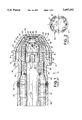
- FIG. 3 is a longitudinal cross-sectional view of a nozzle according to the present invention.
- FIG. 4 is an end elevational view of a swirl plug used in the nozzle of FIG. 3.
- FIG. 5 is a view looking upstream at the primary discharge orifice along a center line of one of the swirl slots in the swirl plug.
- FIG. 6 is a longitudinal cross-sectional view of the nozzle of FIG. 3 assembled in a combustion system which is only partially and schematically illustrated for environmental purposes.
- the prior art spray nozzle designated generally by reference numeral 10, is a dual circuit/orifice, air assisted nozzle.
- the nozzle 10 comprises a nozzle body 12 including a primary nozzle body 14, a secondary nozzle body 16 and an outer air nozzle body 18.
- the nozzle bodies are assembled concentrically with respect to one another and the center axis 20 of the nozzle as shown.
- the primary nozzle body 14 has a conical wall portion 22 which has an interior conical wall surface 24 surrounding a primary swirl chamber 26.
- the primary swirl chamber 26 converges on a circular primary discharge orifice 28 defined by the leading edge of the conical wall portion 22 at the front end of the primary nozzle body 14.
- the rear end of the primary swirl chamber 26 axially opposite the primary discharge orifice 28 is defined by a back wall 30 formed by the front face of a swirl plug 32 located concentrically within a cylindrical portion 34 of the primary nozzle body 14.
- the swirl plug 32 has a conical forward end portion (cone) 36 which seats against the interior conical wall surface 24 of the primary nozzle body 14.
- the cone 36 has formed in the surface thereof a plurality of swirl slots 37 which form with the interior conical wall surface respective swirl channels 38 through which a pressurized primary fluid (i.e., liquid), supplied via an inlet 39 connected to a supply passage 40, is introduced into the primary swirl chamber 26 for swirling therein and discharge out through the primary discharge orifice 28 to form a conical spray.
- a pressurized primary fluid i.e., liquid
- the swirling fluid forms a free vortex whereupon the fluid issuing from the discharge orifice is initially in the form of a conical sheet that, through interaction with air and under typical operating conditions, quickly breaks up into fine drops forming a hollow conical spray.
- the supply passage 40 is formed by the interior passage of a tubular member or supply tube 44 over which the cylindrical portion 34 of the primary nozzle body 14 is telescoped partially and secured by suitable means such as by welding. As shown, the swirl plug 32 is axially trapped between the axial end face of the supply tube 44 and conical wall portion 22 of the primary nozzle body 14.
- the primary nozzle body 14 has a plurality of swirl vanes 48 formed around the periphery of its cylindrical portion 34.
- the secondary nozzle body 16 is telescoped over the primary nozzle body 14 and is supported on the radially outer ends of the swirl vanes 48.
- the primary and secondary nozzle bodies define therebetween an annulus 50 through which a secondary fluid (i.e., liquid) passes, supplied via a secondary fluid inlet 52 from a secondary fluid supply passage 54, to a secondary discharge orifice 56 which, as shown, is coaxial with and spaced slightly axially forward of the primary discharge orifice 28.
- the supply passage 54 is formed by the interior passage of a secondary supply tube 58 to which a cylindrical end portion 60 of the secondary nozzle body is attached as by butt welding.
- the secondary nozzle body 16 has a conical wall portion 64 which has an interior conical wall surface 66 that surrounds the outer conical wall surface 68 of the conical wall portion of the primary nozzle body 14. These conical surfaces 66 and 68 are parallel and define therebetween a conical swirl annulus or chamber 70 generally surrounding the primary swirl chamber 26.
- the secondary swirl chamber 70 converges on the circular secondary discharge orifice 56 defined by the leading edge of the conical wall portion 64 at the front end of the secondary nozzle body 16. Fluid passing into the secondary swirl chamber 70 is caused to swirl therein by the action of the swirl vanes which are inclined to the axis of the nozzle for imparting tangential spin to the fluid passing therethrough, as is well known in the art.
- the swirling secondary fluid is discharged out through the secondary discharge orifice 56 to form a hollow conical spray.
- the secondary conical spray may be separate from or combined with the primary conical spray.
- the secondary nozzle body 16 has a plurality of swirl vanes 78 formed around the periphery of an intermediate cylindrical portion 80 thereof.
- the swirl vanes operate to swirl air that is being introduced from an air inlet 82 into an annulus 84 formed between the secondary nozzle body and the outer nozzle body 18, the latter being telescoped over the secondary nozzle body 16 and supported on the radially outer ends of the swirl vanes 78.
- the nozzle 10 may be surrounded by a housing which channels pressurized air to the air inlet 82.
- the outer air nozzle body 18 has a conical wall portion 88 which has an interior conical wall surface 90 that surrounds the outer conical wall surface 92 of the conical wall portion 64 of the secondary nozzle body 14. These conical surfaces 90 and 92 are parallel and define therebetween a conical swirl annulus or chamber 93 generally surrounding the secondary and primary swirl chambers 26 and 70.
- the air swirl chamber 93 converges on a circular air discharge orifice 94 defined by the leading edge of the conical wall portion 88 at the front end of the outer nozzle body 18. Fluid passing into the air swirl chamber is caused to swirl therein by the action of the swirl vanes which are inclined to the axis of the nozzle for imparting tangential spin to the air passing therethrough, as is well known in the art.
- the swirling air fluid is discharged out through the air discharge orifice 94 for interaction with the conical sprays issuing from the primary and secondary discharge orifices for enhancing atomization of the fluid.
- the air may also be used to influence the conical spray angle.
- the swirl slots 37 in the swirl plug 32 are circumferentially equally spaced apart and are sloped or tangential to the center axis 20 of the nozzle for causing swirling of the fluid in the swirl chamber.
- a forward projection of the cross-section of each swirl slot (or more particularly the swirl channel defined by the swirl slot in conjunction with the interior conical wall surface 24 shown in FIG. 1) along the center line of the swirl slot (channel) will intersect the plane of the discharge orifice radially outwardly of the discharge orifice.
- the center line of the swirl slot (channel) at the exit end of the swirl slot (channel) is a line that points in the direction that fluid is guided by the swirl slot (channel) into the swirl chamber and intersects the geometric center (or centroid) of the fluid flow exiting the swirl slot (channel) into the swirl chamber, the centroid typically being coincident with the center of the cross-sectional area of the slot (channel) perpendicular to the center line.
- center lines of the swirl slots define at the back wall of the swirl chamber (i.e., at the exit openings of the swirl slots, or more particularly the transaxial plane of such exit openings that is intersected by the center lines at circle defining points) a circle having a diameter typically greater than the diameter of the discharge orifice by a factor of 1.25 or more.
- the present invention which resolves the aforesaid problem, is exemplified by the preferred embodiment of spray nozzle shown in FIG. 3 and is denoted by reference numeral 110.
- the spray nozzle 110 is identical to the above described spray nozzle 10 except as otherwise indicated below.
- the elements of the nozzle 110 corresponding to those identified above are denoted by the same reference numeral preceded by a "1" (i.e., incremented by 100).
- the nozzle 110 is a dual circuit/orifice, air assisted nozzle.
- the nozzle 110 comprises a nozzle body 112 including a primary nozzle body 114, a secondary nozzle body 116 and an outer air nozzle body 118.
- the nozzle bodies are assembled concentrically with respect to one another and the center axis 120 of the nozzle as shown.
- the nozzle 110 according to the present invention differs from the prior art nozzle in the following respects.
- the swirl slots 137 are formed radially deeper relative to the swirl slots 37.
- a forward projection of the cross-section of each swirl slot (or more particularly the swirl channel 138 defined by the swirl slot in conjunction with the interior conical wall surface 124) along the center line of the swirl slot (channel) will have a radially inner portion of such projection overlapping the discharge orifice at its intersection with the discharge orifice (or more generally the plane of the discharge orifice).
- the center line of the swirl slot (channel) at the exit end of the swirl slot (channel) is a line that points in the direction that fluid is guided by the swirl slot (channel) into the swirl chamber and intersects the geometric center (or centroid) of the fluid flow exiting the swirl slot (channel) into the swirl chamber, the centroid typically being coincident with the center of the cross-sectional area of the slot (channel) perpendicular to the center line.
- the center lines of the swirl slots define at the back wall of the swirl chamber (i.e., at the exit openings of the swirl slots, or more particularly the transaxial plane of such exit openings that is intersected by the center lines at circle defining points) a circle having a diameter about equal or less than the diameter of the discharge orifice, and thus at a ratio of the diameters that is significantly less than that typically associated with the prior art nozzle.
- the foregoing arrangement is believed to allow some of the primary fluid, such as a liquid fuel, to pass or "jet" through the primary discharge orifice without prefilming on the edge or lip of the discharge orifice.
- streaks or spokes of heavy fuel concentration are produced in the conical spray with a conventional thin film produced fine, uniform mist between the spokes.
- the resultant non-uniform spray provides, for example, better penetration into and mixing of fuel with combustion air that may be supplied, for example, outwardly of a nozzle housing shown in broken lines in FIG. 6.
- the swirler plug may be lengthened in conjunction with the deeper swirl slots. This may be done to maintain the same tip flow number as the nozzle 10 (i.e., the same mass flow rate for the same pressure drop across the nozzle), with all other variables remaining the same except for the depth of the swirl slots.
- an existing design of nozzle such as that shown in FIG. 1, may be easily converted to provide a streaked spray simply by replacing the swirl plug.
- the number of streaks is equal to the number of swirl grooves, such as six.
- the swirl grooves, and consequently the streaks are circumferentially uniformly spaced apart to provide a circumferentially non-uniform but axially symmetric spray.
- the primary liquid entering the swirl chamber passes (or "jets") through the primary discharge orifice and more preferably about 50 to 90 percent and still more preferably about 80 to 90 percent, while the rest resides in the fine mist between the spokes.
- the less dense mist between the spokes will intermix with the more adjacent portion of an air stream (arrows 205) as depicted by broken lines 206, while the more dense spokes, having higher kinetic energy, will penetrate further into the combustion air stream and intermix with more remote air as depicted by broken lines 208.
- the nozzle is shown as installed in a housing 210 which defines with other structure 212 a passageway 214 for the combustion air opening into combustion chamber 216.
- swirl channels may be formed by other than swirl slots, such as for example by swirl holes in the swirl plug or other element.
- swirl channels formed by combinations of swirl slots, swirl holes, swirl vanes, and/or equivalent devices may be utilized to obtain regions of higher density in the conical spray.
- swirl channels may alternate with radially shallower swirl slots or swirl channels, with the result being fewer streaks and/or heavier streaks alternating with lighter streaks.
- one or more swirl channels may be circumferentially spaced apart equally or otherwise to provide other streaked patterns in the conical spray, as may be desired for some applications, and streak-forming swirl channels having center line projections thereof overlapping the discharge orifice may be separate from more radially outwardly disposed swirl channels which impart swirl to the fluid in the swirl chamber alone or in combination with the radially inner streak-forming swirl channels.
- the present invention includes all such alterations and modifications falling within the spirit of the herein described invention.
Abstract
Description
Claims (27)
Priority Applications (1)
| Application Number | Priority Date | Filing Date | Title |
|---|---|---|---|
| US08/397,799 US5697553A (en) | 1995-03-03 | 1995-03-03 | Streaked spray nozzle for enhanced air/fuel mixing |
Applications Claiming Priority (1)
| Application Number | Priority Date | Filing Date | Title |
|---|---|---|---|
| US08/397,799 US5697553A (en) | 1995-03-03 | 1995-03-03 | Streaked spray nozzle for enhanced air/fuel mixing |
Publications (1)
| Publication Number | Publication Date |
|---|---|
| US5697553A true US5697553A (en) | 1997-12-16 |
Family
ID=23572667
Family Applications (1)
| Application Number | Title | Priority Date | Filing Date |
|---|---|---|---|
| US08/397,799 Expired - Fee Related US5697553A (en) | 1995-03-03 | 1995-03-03 | Streaked spray nozzle for enhanced air/fuel mixing |
Country Status (1)
| Country | Link |
|---|---|
| US (1) | US5697553A (en) |
Cited By (27)
| Publication number | Priority date | Publication date | Assignee | Title |
|---|---|---|---|---|
| US5833141A (en) * | 1997-05-30 | 1998-11-10 | General Electric Company | Anti-coking dual-fuel nozzle for a gas turbine combustor |
| WO2000019146A3 (en) * | 1998-09-24 | 2002-10-03 | Pratt & Whitney Canada | Fuel spray nozzle |
| US6460344B1 (en) | 1999-05-07 | 2002-10-08 | Parker-Hannifin Corporation | Fuel atomization method for turbine combustion engines having aerodynamic turning vanes |
| US20030115880A1 (en) * | 2001-12-21 | 2003-06-26 | Roberto Modi | Liquid fuel injector for burners of gas turbines |
| US20030196440A1 (en) * | 1999-05-07 | 2003-10-23 | Erlendur Steinthorsson | Fuel nozzle for turbine combustion engines having aerodynamic turning vanes |
| US20050242209A1 (en) * | 2002-12-20 | 2005-11-03 | Per Holm | Self-cleaning spray nozzle |
| US20060059915A1 (en) * | 2004-09-23 | 2006-03-23 | Snecma | Effervescence injector for an aero-mechanical system for injecting air/fuel mixture into a turbomachine combustion chamber |
| US20080233014A1 (en) * | 1998-06-04 | 2008-09-25 | Southwick Kenneth J | Collider Chamber Apparatus and Method of Use of Same |
| US20090057439A1 (en) * | 2005-07-07 | 2009-03-05 | Metso Automation Oy | Moistening Nozzle of a Paper Web |
| US20090224080A1 (en) * | 2008-03-04 | 2009-09-10 | Delavan Inc | Pure Air Blast Fuel Injector |
| US20090250407A1 (en) * | 2008-04-04 | 2009-10-08 | Delano Roger A | System and method of water treatment |
| US20100170267A1 (en) * | 2006-12-22 | 2010-07-08 | Boeettcher Andreas | Burner for a gas turbine |
| US20100223929A1 (en) * | 2009-03-03 | 2010-09-09 | General Electric Company | System for fuel injection in a turbine engine |
| US20110149676A1 (en) * | 2009-10-09 | 2011-06-23 | Southwick Kenneth J | Methods of and Systems for Introducing Acoustic Energy into a Fluid in a Collider Chamber Apparatus |
| US20110272486A1 (en) * | 2004-12-15 | 2011-11-10 | Harry Metzger | Method for spraying a medium and spraying nozzle |
| US8893500B2 (en) | 2011-05-18 | 2014-11-25 | Solar Turbines Inc. | Lean direct fuel injector |
| US8919132B2 (en) | 2011-05-18 | 2014-12-30 | Solar Turbines Inc. | Method of operating a gas turbine engine |
| US9182124B2 (en) | 2011-12-15 | 2015-11-10 | Solar Turbines Incorporated | Gas turbine and fuel injector for the same |
| US20160010855A1 (en) * | 2014-07-11 | 2016-01-14 | Delavan Inc. | Swirl slot relief in a liquid swirler |
| US20160236215A1 (en) * | 2015-02-18 | 2016-08-18 | Delavan Inc | Atomizers |
| US20160341427A1 (en) * | 2015-05-21 | 2016-11-24 | Doosan Heavy Industries & Construction Co., Ltd. | Fuel supply nozzle for minimizing burning damage |
| US20170184307A1 (en) * | 2015-12-29 | 2017-06-29 | Pratt & Whitney Canada Corp. | Fuel injector for fuel spray nozzle |
| CN114087627A (en) * | 2021-11-11 | 2022-02-25 | 中国航发贵州黎阳航空动力有限公司 | Miniature aircraft engine fuel manifold nozzle and oil mixing test method thereof |
| RU2770129C1 (en) * | 2021-03-31 | 2022-04-14 | Михаил Алексеевич Бажанов | Sprayer nozzle |
| US20220163205A1 (en) * | 2020-11-24 | 2022-05-26 | Pratt & Whitney Canada Corp. | Fuel swirler for pressure fuel nozzles |
| US11426742B2 (en) * | 2020-01-28 | 2022-08-30 | Collins Engine Nozzles, Inc. | Spray nozzle |
| CN115055017A (en) * | 2022-06-23 | 2022-09-16 | 重庆大学 | Oblique spiral-flow type centrifugal atomization spraying device |
Citations (22)
| Publication number | Priority date | Publication date | Assignee | Title |
|---|---|---|---|---|
| GB191400385A (en) * | 1914-01-06 | 1914-12-24 | William Edward Martin | Improvements in Carburetters or Fuel-spraying Nozzles for Internal Combustion Engines. |
| CH265947A (en) * | 1947-04-02 | 1949-12-31 | Rolls Royce | Fuel injector. |
| GB702215A (en) * | 1950-10-09 | 1954-01-13 | Power Jets Res & Dev Ltd | Liquid fuel burner |
| US3013732A (en) * | 1959-09-01 | 1961-12-19 | Parker Hannifin Corp | Fuel injection nozzle |
| US3024045A (en) * | 1959-05-27 | 1962-03-06 | Parker Hannifin Corp | Fuel injection nozzle |
| US3028102A (en) * | 1957-08-14 | 1962-04-03 | Parker Hannifin Corp | Liquid fuel spray nozzle |
| US3029029A (en) * | 1959-05-26 | 1962-04-10 | Parker Hannifin Corp | Dual-orifice return flow nozzle |
| US3474970A (en) * | 1967-03-15 | 1969-10-28 | Parker Hannifin Corp | Air assist nozzle |
| US3946552A (en) * | 1973-09-10 | 1976-03-30 | General Electric Company | Fuel injection apparatus |
| US3972182A (en) * | 1973-09-10 | 1976-08-03 | General Electric Company | Fuel injection apparatus |
| US3979069A (en) * | 1974-10-11 | 1976-09-07 | Luigi Garofalo | Air-atomizing fuel nozzle |
| US3980233A (en) * | 1974-10-07 | 1976-09-14 | Parker-Hannifin Corporation | Air-atomizing fuel nozzle |
| US4139157A (en) * | 1976-09-02 | 1979-02-13 | Parker-Hannifin Corporation | Dual air-blast fuel nozzle |
| US4168803A (en) * | 1977-08-31 | 1979-09-25 | Parker-Hannifin Corporation | Air-ejector assisted fuel nozzle |
| US4365753A (en) * | 1980-08-22 | 1982-12-28 | Parker-Hannifin Corporation | Boundary layer prefilmer airblast nozzle |
| US4595143A (en) * | 1983-07-20 | 1986-06-17 | Parker-Hannifin Corporation | Air swirl nozzle |
| US4613079A (en) * | 1984-10-25 | 1986-09-23 | Parker-Hannifin Corporation | Fuel nozzle with disc filter |
| US4616784A (en) * | 1984-11-20 | 1986-10-14 | Parker Hannifin Corporation | Slurry atomizer |
| US4754922A (en) * | 1986-07-24 | 1988-07-05 | Ex-Cell-O Corporation | Airblast fuel injector tip with integral cantilever spring fuel metering valve and method for reducing vapor lock from high temperature |
| US5067655A (en) * | 1987-12-11 | 1991-11-26 | Deutsche Forschungsanstalt Fuer Luft- Und Raumfahrt | Whirl nozzle for atomizing a liquid |
| US5105621A (en) * | 1991-08-16 | 1992-04-21 | Parker-Hannifin Corporation | Exhaust system combustor |
| US5251823A (en) * | 1992-08-10 | 1993-10-12 | Combustion Tec, Inc. | Adjustable atomizing orifice liquid fuel burner |
-
1995
- 1995-03-03 US US08/397,799 patent/US5697553A/en not_active Expired - Fee Related
Patent Citations (22)
| Publication number | Priority date | Publication date | Assignee | Title |
|---|---|---|---|---|
| GB191400385A (en) * | 1914-01-06 | 1914-12-24 | William Edward Martin | Improvements in Carburetters or Fuel-spraying Nozzles for Internal Combustion Engines. |
| CH265947A (en) * | 1947-04-02 | 1949-12-31 | Rolls Royce | Fuel injector. |
| GB702215A (en) * | 1950-10-09 | 1954-01-13 | Power Jets Res & Dev Ltd | Liquid fuel burner |
| US3028102A (en) * | 1957-08-14 | 1962-04-03 | Parker Hannifin Corp | Liquid fuel spray nozzle |
| US3029029A (en) * | 1959-05-26 | 1962-04-10 | Parker Hannifin Corp | Dual-orifice return flow nozzle |
| US3024045A (en) * | 1959-05-27 | 1962-03-06 | Parker Hannifin Corp | Fuel injection nozzle |
| US3013732A (en) * | 1959-09-01 | 1961-12-19 | Parker Hannifin Corp | Fuel injection nozzle |
| US3474970A (en) * | 1967-03-15 | 1969-10-28 | Parker Hannifin Corp | Air assist nozzle |
| US3946552A (en) * | 1973-09-10 | 1976-03-30 | General Electric Company | Fuel injection apparatus |
| US3972182A (en) * | 1973-09-10 | 1976-08-03 | General Electric Company | Fuel injection apparatus |
| US3980233A (en) * | 1974-10-07 | 1976-09-14 | Parker-Hannifin Corporation | Air-atomizing fuel nozzle |
| US3979069A (en) * | 1974-10-11 | 1976-09-07 | Luigi Garofalo | Air-atomizing fuel nozzle |
| US4139157A (en) * | 1976-09-02 | 1979-02-13 | Parker-Hannifin Corporation | Dual air-blast fuel nozzle |
| US4168803A (en) * | 1977-08-31 | 1979-09-25 | Parker-Hannifin Corporation | Air-ejector assisted fuel nozzle |
| US4365753A (en) * | 1980-08-22 | 1982-12-28 | Parker-Hannifin Corporation | Boundary layer prefilmer airblast nozzle |
| US4595143A (en) * | 1983-07-20 | 1986-06-17 | Parker-Hannifin Corporation | Air swirl nozzle |
| US4613079A (en) * | 1984-10-25 | 1986-09-23 | Parker-Hannifin Corporation | Fuel nozzle with disc filter |
| US4616784A (en) * | 1984-11-20 | 1986-10-14 | Parker Hannifin Corporation | Slurry atomizer |
| US4754922A (en) * | 1986-07-24 | 1988-07-05 | Ex-Cell-O Corporation | Airblast fuel injector tip with integral cantilever spring fuel metering valve and method for reducing vapor lock from high temperature |
| US5067655A (en) * | 1987-12-11 | 1991-11-26 | Deutsche Forschungsanstalt Fuer Luft- Und Raumfahrt | Whirl nozzle for atomizing a liquid |
| US5105621A (en) * | 1991-08-16 | 1992-04-21 | Parker-Hannifin Corporation | Exhaust system combustor |
| US5251823A (en) * | 1992-08-10 | 1993-10-12 | Combustion Tec, Inc. | Adjustable atomizing orifice liquid fuel burner |
Non-Patent Citations (2)
| Title |
|---|
| Simmons, Harold C., Booklet entitled "The Atomization of Liquids", 1979. |
| Simmons, Harold C., Booklet entitled The Atomization of Liquids , 1979. * |
Cited By (49)
| Publication number | Priority date | Publication date | Assignee | Title |
|---|---|---|---|---|
| US5833141A (en) * | 1997-05-30 | 1998-11-10 | General Electric Company | Anti-coking dual-fuel nozzle for a gas turbine combustor |
| US20080233014A1 (en) * | 1998-06-04 | 2008-09-25 | Southwick Kenneth J | Collider Chamber Apparatus and Method of Use of Same |
| US7744826B2 (en) * | 1998-06-04 | 2010-06-29 | Transkinetic Energy Corporation | Collider chamber apparatus and method of use of same |
| WO2000019146A3 (en) * | 1998-09-24 | 2002-10-03 | Pratt & Whitney Canada | Fuel spray nozzle |
| US6883332B2 (en) | 1999-05-07 | 2005-04-26 | Parker-Hannifin Corporation | Fuel nozzle for turbine combustion engines having aerodynamic turning vanes |
| US6460344B1 (en) | 1999-05-07 | 2002-10-08 | Parker-Hannifin Corporation | Fuel atomization method for turbine combustion engines having aerodynamic turning vanes |
| US6560964B2 (en) | 1999-05-07 | 2003-05-13 | Parker-Hannifin Corporation | Fuel nozzle for turbine combustion engines having aerodynamic turning vanes |
| US20030196440A1 (en) * | 1999-05-07 | 2003-10-23 | Erlendur Steinthorsson | Fuel nozzle for turbine combustion engines having aerodynamic turning vanes |
| US6817183B2 (en) * | 2001-12-21 | 2004-11-16 | Nuovo Pignone Holding S.P.A. | Liquid fuel injector for burners of gas turbines |
| US20030115880A1 (en) * | 2001-12-21 | 2003-06-26 | Roberto Modi | Liquid fuel injector for burners of gas turbines |
| US7252247B2 (en) * | 2002-12-20 | 2007-08-07 | Lifecycle Pharma A/S | Self-cleaning spray nozzle |
| US20050242209A1 (en) * | 2002-12-20 | 2005-11-03 | Per Holm | Self-cleaning spray nozzle |
| US20060059915A1 (en) * | 2004-09-23 | 2006-03-23 | Snecma | Effervescence injector for an aero-mechanical system for injecting air/fuel mixture into a turbomachine combustion chamber |
| FR2875584A1 (en) * | 2004-09-23 | 2006-03-24 | Snecma Moteurs Sa | EFFERVESCENCE INJECTOR FOR AEROMECHANICAL AIR / FUEL INJECTION SYSTEM IN A TURBOMACHINE COMBUSTION CHAMBER |
| EP1640662A1 (en) * | 2004-09-23 | 2006-03-29 | Snecma | Effervescent injector for an aeromechanical air/fuel injection system integrated into a gas turbine combustor |
| US7568345B2 (en) | 2004-09-23 | 2009-08-04 | Snecma | Effervescence injector for an aero-mechanical system for injecting air/fuel mixture into a turbomachine combustion chamber |
| JP2006090326A (en) * | 2004-09-23 | 2006-04-06 | Snecma | Foaming injection machine for pneumatic mechanical type system for injecting air/fuel mixture into turbo-machine combustion chamber |
| JP4632913B2 (en) * | 2004-09-23 | 2011-02-16 | スネクマ | Foam injector for an air mechanical system that injects an air / fuel mixture into a turbomachine combustion chamber |
| US8636232B2 (en) * | 2004-12-15 | 2014-01-28 | Marioff Corporation Oy | Method for spraying a medium and spraying nozzle |
| US20110272486A1 (en) * | 2004-12-15 | 2011-11-10 | Harry Metzger | Method for spraying a medium and spraying nozzle |
| US20090057439A1 (en) * | 2005-07-07 | 2009-03-05 | Metso Automation Oy | Moistening Nozzle of a Paper Web |
| US8393555B2 (en) | 2005-07-07 | 2013-03-12 | Metso Automation Oy | Moistening nozzle of a paper web |
| US8869534B2 (en) * | 2006-12-22 | 2014-10-28 | Siemens Aktiengesellschaft | Burner for a gas turbine |
| US20100170267A1 (en) * | 2006-12-22 | 2010-07-08 | Boeettcher Andreas | Burner for a gas turbine |
| US20090224080A1 (en) * | 2008-03-04 | 2009-09-10 | Delavan Inc | Pure Air Blast Fuel Injector |
| US7926282B2 (en) * | 2008-03-04 | 2011-04-19 | Delavan Inc | Pure air blast fuel injector |
| US8388850B2 (en) | 2008-04-04 | 2013-03-05 | Neos International, Llc | System and method of water treatment |
| US20090250407A1 (en) * | 2008-04-04 | 2009-10-08 | Delano Roger A | System and method of water treatment |
| US8347631B2 (en) * | 2009-03-03 | 2013-01-08 | General Electric Company | Fuel nozzle liquid cartridge including a fuel insert |
| US20100223929A1 (en) * | 2009-03-03 | 2010-09-09 | General Electric Company | System for fuel injection in a turbine engine |
| US20110149676A1 (en) * | 2009-10-09 | 2011-06-23 | Southwick Kenneth J | Methods of and Systems for Introducing Acoustic Energy into a Fluid in a Collider Chamber Apparatus |
| US8919132B2 (en) | 2011-05-18 | 2014-12-30 | Solar Turbines Inc. | Method of operating a gas turbine engine |
| US8893500B2 (en) | 2011-05-18 | 2014-11-25 | Solar Turbines Inc. | Lean direct fuel injector |
| US9182124B2 (en) | 2011-12-15 | 2015-11-10 | Solar Turbines Incorporated | Gas turbine and fuel injector for the same |
| US9625146B2 (en) * | 2014-07-11 | 2017-04-18 | Delavan Inc. | Swirl slot relief in a liquid swirler |
| US20160010855A1 (en) * | 2014-07-11 | 2016-01-14 | Delavan Inc. | Swirl slot relief in a liquid swirler |
| US9901944B2 (en) * | 2015-02-18 | 2018-02-27 | Delavan Inc | Atomizers |
| US20160236215A1 (en) * | 2015-02-18 | 2016-08-18 | Delavan Inc | Atomizers |
| US11628455B2 (en) | 2015-02-18 | 2023-04-18 | Collins Engine Nozzles, Inc. | Atomizers |
| US20160341427A1 (en) * | 2015-05-21 | 2016-11-24 | Doosan Heavy Industries & Construction Co., Ltd. | Fuel supply nozzle for minimizing burning damage |
| US10359195B2 (en) * | 2015-05-21 | 2019-07-23 | DOOSAN Heavy Industries Construction Co., LTD | Fuel supply nozzle for minimizing burning damage |
| US20170184307A1 (en) * | 2015-12-29 | 2017-06-29 | Pratt & Whitney Canada Corp. | Fuel injector for fuel spray nozzle |
| US10047959B2 (en) * | 2015-12-29 | 2018-08-14 | Pratt & Whitney Canada Corp. | Fuel injector for fuel spray nozzle |
| US11426742B2 (en) * | 2020-01-28 | 2022-08-30 | Collins Engine Nozzles, Inc. | Spray nozzle |
| US20220163205A1 (en) * | 2020-11-24 | 2022-05-26 | Pratt & Whitney Canada Corp. | Fuel swirler for pressure fuel nozzles |
| RU2770129C1 (en) * | 2021-03-31 | 2022-04-14 | Михаил Алексеевич Бажанов | Sprayer nozzle |
| CN114087627A (en) * | 2021-11-11 | 2022-02-25 | 中国航发贵州黎阳航空动力有限公司 | Miniature aircraft engine fuel manifold nozzle and oil mixing test method thereof |
| CN115055017A (en) * | 2022-06-23 | 2022-09-16 | 重庆大学 | Oblique spiral-flow type centrifugal atomization spraying device |
| CN115055017B (en) * | 2022-06-23 | 2023-08-04 | 重庆大学 | Oblique swirl centrifugal atomization spraying device |
Similar Documents
| Publication | Publication Date | Title |
|---|---|---|
| US5697553A (en) | Streaked spray nozzle for enhanced air/fuel mixing | |
| US6863228B2 (en) | Discrete jet atomizer | |
| US3790086A (en) | Atomizing nozzle | |
| JP4049893B2 (en) | Pressure atomizing nozzle | |
| US4087050A (en) | Swirl type pressure fuel atomizer | |
| US5713205A (en) | Air atomized discrete jet liquid fuel injector and method | |
| EP1090256B1 (en) | Fuel injector for gas turbine engine | |
| US3980233A (en) | Air-atomizing fuel nozzle | |
| US6082113A (en) | Gas turbine fuel injector | |
| US8348180B2 (en) | Conical swirler for fuel injectors and combustor domes and methods of manufacturing the same | |
| US5813847A (en) | Device and method for injecting fuels into compressed gaseous media | |
| US5934555A (en) | Pressure atomizer nozzle | |
| EP0140477B1 (en) | Air swirl nozzle | |
| US20030155325A1 (en) | Integrated fluid injection air mixing system | |
| JPS6161015B2 (en) | ||
| JPH0787907B2 (en) | Improved spray nozzle design | |
| US4946105A (en) | Fuel nozzle for gas turbine engine | |
| US4311277A (en) | Fuel injector | |
| JP2000107651A (en) | Two-fluid nozzle | |
| US4365753A (en) | Boundary layer prefilmer airblast nozzle | |
| KR20060060716A (en) | A nozzle for air-assisted atomization of a liquid fuel | |
| US10094352B2 (en) | Swirl impingement prefilming | |
| US7735756B2 (en) | Advanced mechanical atomization for oil burners | |
| US5860600A (en) | Atomizer (low opacity) | |
| US5269495A (en) | High-pressure atomizing nozzle |
Legal Events
| Date | Code | Title | Description |
|---|---|---|---|
| AS | Assignment |
Owner name: PARKER-HANNIFIN CORPORATION, OHIO Free format text: ASSIGNMENT OF ASSIGNORS INTEREST;ASSIGNOR:STOTTS, ROBERT E.;REEL/FRAME:007368/0366 Effective date: 19950303 |
|
| AS | Assignment |
Owner name: PARKER INTANGIBLES INC., DELAWARE Free format text: ASSIGNMENT OF ASSIGNORS INTEREST;ASSIGNOR:PARKER-HANNIFIN CORPORATION;REEL/FRAME:009375/0659 Effective date: 19980805 |
|
| AS | Assignment |
Owner name: PARKER HANNIFAN CUSTOMER SUPPORT INC., CALIFORNIA Free format text: MERGER;ASSIGNOR:PARKER INTANGIBLES INC.;REEL/FRAME:010308/0269 Effective date: 19981231 |
|
| FPAY | Fee payment |
Year of fee payment: 4 |
|
| AS | Assignment |
Owner name: PARKER INTANGIBLES LLC, OHIO Free format text: MERGER;ASSIGNOR:PARKER HANNIFIN CUSTOMER SUPPORT INC.;REEL/FRAME:015215/0522 Effective date: 20030630 |
|
| FEPP | Fee payment procedure |
Free format text: PAYOR NUMBER ASSIGNED (ORIGINAL EVENT CODE: ASPN); ENTITY STATUS OF PATENT OWNER: LARGE ENTITY |
|
| FPAY | Fee payment |
Year of fee payment: 8 |
|
| FEPP | Fee payment procedure |
Free format text: PAYER NUMBER DE-ASSIGNED (ORIGINAL EVENT CODE: RMPN); ENTITY STATUS OF PATENT OWNER: LARGE ENTITY Free format text: PAYOR NUMBER ASSIGNED (ORIGINAL EVENT CODE: ASPN); ENTITY STATUS OF PATENT OWNER: LARGE ENTITY |
|
| REMI | Maintenance fee reminder mailed | ||
| LAPS | Lapse for failure to pay maintenance fees | ||
| STCH | Information on status: patent discontinuation |
Free format text: PATENT EXPIRED DUE TO NONPAYMENT OF MAINTENANCE FEES UNDER 37 CFR 1.362 |
|
| FP | Lapsed due to failure to pay maintenance fee |
Effective date: 20091216 |