US5682273A - Disk drive for portable computer with adaptive demand-driven power management - Google Patents
Disk drive for portable computer with adaptive demand-driven power management Download PDFInfo
- Publication number
- US5682273A US5682273A US08/532,956 US53295695A US5682273A US 5682273 A US5682273 A US 5682273A US 53295695 A US53295695 A US 53295695A US 5682273 A US5682273 A US 5682273A
- Authority
- US
- United States
- Prior art keywords
- power
- access
- disk drive
- save mode
- frequency
- Prior art date
- Legal status (The legal status is an assumption and is not a legal conclusion. Google has not performed a legal analysis and makes no representation as to the accuracy of the status listed.)
- Expired - Lifetime
Links
Images


Classifications
-
- G—PHYSICS
- G06—COMPUTING; CALCULATING OR COUNTING
- G06F—ELECTRIC DIGITAL DATA PROCESSING
- G06F1/00—Details not covered by groups G06F3/00 - G06F13/00 and G06F21/00
- G06F1/26—Power supply means, e.g. regulation thereof
- G06F1/32—Means for saving power
- G06F1/3203—Power management, i.e. event-based initiation of a power-saving mode
- G06F1/3206—Monitoring of events, devices or parameters that trigger a change in power modality
- G06F1/3215—Monitoring of peripheral devices
- G06F1/3221—Monitoring of peripheral devices of disk drive devices
-
- G—PHYSICS
- G06—COMPUTING; CALCULATING OR COUNTING
- G06F—ELECTRIC DIGITAL DATA PROCESSING
- G06F1/00—Details not covered by groups G06F3/00 - G06F13/00 and G06F21/00
- G06F1/26—Power supply means, e.g. regulation thereof
- G06F1/32—Means for saving power
- G06F1/3203—Power management, i.e. event-based initiation of a power-saving mode
- G06F1/3234—Power saving characterised by the action undertaken
- G06F1/325—Power saving in peripheral device
- G06F1/3268—Power saving in hard disk drive
-
- G—PHYSICS
- G06—COMPUTING; CALCULATING OR COUNTING
- G06F—ELECTRIC DIGITAL DATA PROCESSING
- G06F3/00—Input arrangements for transferring data to be processed into a form capable of being handled by the computer; Output arrangements for transferring data from processing unit to output unit, e.g. interface arrangements
- G06F3/06—Digital input from, or digital output to, record carriers, e.g. RAID, emulated record carriers or networked record carriers
- G06F3/0601—Interfaces specially adapted for storage systems
-
- G—PHYSICS
- G11—INFORMATION STORAGE
- G11B—INFORMATION STORAGE BASED ON RELATIVE MOVEMENT BETWEEN RECORD CARRIER AND TRANSDUCER
- G11B19/00—Driving, starting, stopping record carriers not specifically of filamentary or web form, or of supports therefor; Control thereof; Control of operating function ; Driving both disc and head
-
- G—PHYSICS
- G06—COMPUTING; CALCULATING OR COUNTING
- G06F—ELECTRIC DIGITAL DATA PROCESSING
- G06F3/00—Input arrangements for transferring data to be processed into a form capable of being handled by the computer; Output arrangements for transferring data from processing unit to output unit, e.g. interface arrangements
- G06F3/06—Digital input from, or digital output to, record carriers, e.g. RAID, emulated record carriers or networked record carriers
- G06F3/0601—Interfaces specially adapted for storage systems
- G06F3/0668—Interfaces specially adapted for storage systems adopting a particular infrastructure
- G06F3/0671—In-line storage system
- G06F3/0673—Single storage device
-
- Y—GENERAL TAGGING OF NEW TECHNOLOGICAL DEVELOPMENTS; GENERAL TAGGING OF CROSS-SECTIONAL TECHNOLOGIES SPANNING OVER SEVERAL SECTIONS OF THE IPC; TECHNICAL SUBJECTS COVERED BY FORMER USPC CROSS-REFERENCE ART COLLECTIONS [XRACs] AND DIGESTS
- Y02—TECHNOLOGIES OR APPLICATIONS FOR MITIGATION OR ADAPTATION AGAINST CLIMATE CHANGE
- Y02D—CLIMATE CHANGE MITIGATION TECHNOLOGIES IN INFORMATION AND COMMUNICATION TECHNOLOGIES [ICT], I.E. INFORMATION AND COMMUNICATION TECHNOLOGIES AIMING AT THE REDUCTION OF THEIR OWN ENERGY USE
- Y02D10/00—Energy efficient computing, e.g. low power processors, power management or thermal management
-
- Y—GENERAL TAGGING OF NEW TECHNOLOGICAL DEVELOPMENTS; GENERAL TAGGING OF CROSS-SECTIONAL TECHNOLOGIES SPANNING OVER SEVERAL SECTIONS OF THE IPC; TECHNICAL SUBJECTS COVERED BY FORMER USPC CROSS-REFERENCE ART COLLECTIONS [XRACs] AND DIGESTS
- Y02—TECHNOLOGIES OR APPLICATIONS FOR MITIGATION OR ADAPTATION AGAINST CLIMATE CHANGE
- Y02D—CLIMATE CHANGE MITIGATION TECHNOLOGIES IN INFORMATION AND COMMUNICATION TECHNOLOGIES [ICT], I.E. INFORMATION AND COMMUNICATION TECHNOLOGIES AIMING AT THE REDUCTION OF THEIR OWN ENERGY USE
- Y02D30/00—Reducing energy consumption in communication networks
- Y02D30/50—Reducing energy consumption in communication networks in wire-line communication networks, e.g. low power modes or reduced link rate
Definitions
- This invention relates in general to disk drives used in portable computers, such as laptop or notebook computers, that are battery powered.
- the invention relates to such disk drives that include techniques for minimizing energy consumption.
- Portable computers can only function for several hours before draining their battery sources.
- a major power user is the hard disk drive.
- the primary power management technique for the hard disk drive in portable computers is the use of several reduced-power or power-save operating modes, each mode being entered following time out of a fixed predetermined time period since a disk drive read or write operation. For example, at the end of a fixed time period since the user last wrote data to the hard disk, the read/write heads are moved to their parking location and the disk drive spindle motor is shut off. When the user next accesses the disk drive, the spindle motor is spun up and the heads are moved across the disk to read or write data on the appropriate data track.
- the primary disadvantage of such a power-save mode is the time delay in exiting the mode, during which the user must wait. This greatly affects the performance of the computer. Typically, the lengths of the fixed time periods are set by the computer user through software.
- Short mode entry times save energy when the access pattern has bursts of activity followed by long periods of inactivity. However, excess energy is used when the inactive periods are close to the mode entry time. Performance may also be impacted since the modes are entered after short periods of inactivity, typically resulting in more frequent access delays due to mode recovery times.
- the user wants to choose between energy consumption and computer performance, not between fixed mode entry times.
- the user's choice of fixed mode entry times is merely a guess at achieving some energy or performance goal.
- What is needed is a disk drive method and system for achieving power management that can detect and adapt to changing workloads, and that can use energy and performance goals, instead of fixed times, to determine when to enter and exit power-save modes.
- the disk drive of the present invention perform power management from past disk drive access history and a prediction of future user demands to determine the power-save mode entry and exit times. This has the advantage over the current user-selectable predetermined or fixed mode-entry times since the user does not know what performance and energy-consumption costs are associated with entry and exit from the power-save modes.
- the disk drive has information on the energy break-even times and recovery times associated with the power-save modes.
- the energy break-even time is the time the drive needs to remain in the particular power-save mode so that the extra energy consumed during recovery from that mode balances the reduced energy consumption while in that mode.
- the recovery time is the amount of time it takes the disk drive to return from a power-save mode to the active state.
- the disk drive keeps track of the access patterns, i.e., the history of requests to read or write data and/or move the actuator.
- the disk drive thus detects the current user workload and determines which of a plurality of power-save modes is appropriate and when to enter a mode.
- each disk drive access is detected and used to compute a current access frequency.
- the current access frequency is compared to a previously calculated and continuously updated threshold frequency.
- the threshold frequency is representative of the access pattern, e.g., uniform or sporadic, and is computed from equations that include adjustable gain factors.
- the appropriate power-save mode is entered when the current access frequency falls below the threshold frequency. Intermediate power-save modes can be skipped, based on the detected access pattern.
- the disk drive can also adapt dynamically to varying workload situations, thereby saving more energy without degrading performance. This is accomplished by adjusting the gain factors in response to tracking the actual performance of the system, thereby changing the threshold frequency.
- the disk drive also determines when to exit a power-save mode without necessarily waiting for a user access. In the present invention, there can thus be many power-save modes that would otherwise be impractical for a user to keep track of.
- the power-save modes can also be customized for different disk drive products without the need to conform to some standard for setting fixed times, or number of power-save modes. New user-selectable parameters, such as on/off, performance, and energy targets can be used to replace fixed mode-entry times. These parameters adjust the gain factors and thus the threshold frequency. This alters the equations used to determine when to enter a power-save mode.
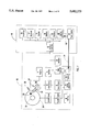
- FIG. 1 is a block diagram of the disk drive and computer system illustrating the power source and the various energy-consuming disk drive components.
- FIG. 2 is a flow chart illustrating the counting of accesses to one or more power-consuming disk drive components within a predetermined time window.
- FIG. 3 is a block diagram illustrating a microprocessor coupled to a ring buffer that accumulates access densities.
- FIG. 4 is a flow chart illustrating the computation of the access frequency and comparison to a threshold frequency for determining when to enter a disk drive power-save mode.
- FIG. 5 a flow chart illustrating the computation of the threshold frequency using prior access frequencies stored in a ring buffer.
- FIG. 6 a flow chart illustrating the computation of the threshold frequency using prior access densities stored in a ring buffer.
- FIG. 7 is a plot illustrating a time sequence for the entry and exit of a power-save mode.
- FIG. 8 is a block diagram like that of FIG. 3 but with the addition of a counter for counting time windows between the entry and exit of a power-save mode.
- FIG. 9 is a plot of cumulative energy/response penalty as a function of time for illustrating adjustment of the gain factors when the trip level is crossed.
- FIG. 10 is a flow chart illustrating the computation of the energy/response and missed opportunity penalties when a power-save mode is exited.
- FIG. 11 is a flow chart illustrating the computation of the cumulative missed opportunity penalty and adjustment of the gain factors when the trip level is crossed.
- FIG. 1 is a block diagram showing the various elements in power management for the disk drive of the present invention.
- the disk drive 40 is typically a hard disk drive contained within the housing of a laptop computer, such as computer 41.
- the disk drive 40 contains one or more disks, such as typical disk 34, attached to and rotated by spindle motor 32.
- a data head 33 is connected to an actuator 31 that is typically operated by a rotary voice coil motor (VCM) 30.
- Spindle motor 32 is driven by spindle driver 1 and spindle control electronics 5.
- Servo control electronics 6 is used to position the head 33 over the various data tracks of disk 33 and is connected to VCM driver 2, which supplies current to the VCM 30. Also shown in FIG.
- a crash stop 37 for actuator 31 and a load/unload (L/UL) ramp 38 are a crash stop 37 for actuator 31 and a load/unload (L/UL) ramp 38.
- the disk drive 40 is the contact start/stop (CSS) type wherein the head 33 resides on disk 34 when the spindle motor is not rotating, then the actuator is driven to the crash stop 37 by current to VCM 30 so that the head 33 can come to rest on a nondata landing zone near the disk inside diameter (ID).
- ID nondata landing zone near the disk inside diameter
- the disk drive 40 is the L/UL type, then at spindle motor shutdown the actuator 31 is driven so that the suspension supporting the head 33 rides up the ramp 38 and unloads the head 33 from contact with the disk.
- the ID landing zone for a CSS disk drive and the ramp for a L/UL disk drive are often referred to as head-parking locations.
- Data head 33 reads and writes user data on disk 34, and is typically a thin film inductive (TFI) read/write head or a TFI write head with a magnetoresistive (MR) read head.
- Data head 33 is connected to preamplifier and write driver 3, data recording channel 4, and disk controller electronics 7.
- Data recording channel 4 may be any type, such as peak detector or partial-response maximum likelihood (PRML), and includes such functions as data detection, encoding and decoding.
- Disk controller 7, in connection with microprocessor 9, handles the processes of reading and writing data, coordinates communications with computer 41, manages buffer memory 10, and directs servo control electronics 6 and spindle control electronics 5.
- Disk drive 40 also includes a microprocessor 9 and associated memory 8, buffer memory 10, interface module 11, and a power control module 12.
- Microprocessor memory 8 is used to store code and data for microprocessor 9.
- Buffer memory 10 is used to store data being transferred from the computer 41 to the disk drive 40, and is typically configured as a cache memory.
- Interface module 11 controls the transmission of information over the interface from computer interface controller 13.
- the integrated drive electronics (IDE) interface and small computer system interface (SCSI) are the most common type of interfaces.
- Power control module 12 controls the power management of the disk drive 40, which receives power from power source 20 via bus 71.
- the power connection to all of the components is not shown in FIG. 1, but each of them receives power either directly off bus 71 or through another component.
- the power control module 12 may be physically contained as logic circuitry within controller 7, and/or be in the form of microcode stored in memory 8 for execution by microprocessor 9.
- the power lines from power source 20 to each of the energy-consuming components can be directly controlled by module 12 or the output of microprocessor 9, or commands can be issued to the components to turn off, turn on and/or otherwise change their power state.
- microprocessor memory 8 may be contained within the microprocessor 9, or combined with buffer memory 10.
- servo control electronics 6 may include a separate servo microprocessor.
- Computer 41 comprises interface controller 13, processor 14, memory 15, display 16, keyboard 17, and/or other input devices, peripherals 18, power source 20, and control electronics 19.
- Interface controller 13 handles communication with disk drive 40.
- Power source 20 is the power source for computer 41 and disk drive 40. For portable applications this is typically a rechargeable battery, although it may be any other type of power source, such as an A/C power supply.
- Power source 20 provides power to the various components in the computer 41 through bus 70 and to the disk drive 40 through bus 71.
- Power source 20 also communicates with control electronics 19.
- the batteries in portable computers contain internal control electronics that monitor the battery status, such as the discharge state.
- the disk drive 40 does not consume energy at a constant rate. More energy is consumed when seeking (i.e., movement of the head 33 across the data tracks of disk 34 by application of current to VCM 30) than when track following (i.e., maintaining of the head 33 on a single data track by intermittent current pulses to VCM 30). Also, additional energy is consumed during write operations because write current is applied to the coil of the TFI head.
- the seek/read/write power mode is typically an estimate since it is based on an assumption of the user workload.
- the idle power mode is the normal track-following operation when data is not being read or written, and no seek is occurring.
- the term active state is used to refer to the disk drive when it is in either the seek/read/write or the idle power modes.
- the two common power-save modes are referred to as idle2 and standby.
- the idle2 mode the actuator 31 is parked (i.e., moved to crash stop 30 or unloaded onto ramp 37), and the servo control electronics 6 and read/write electronics, including preamplifier 3 and channel 4, are turned off.
- the idle2 mode thus substantially reduces or removes power to VCM driver 2, servo control electronics 6, preamplifier 3 and channel 4.
- the idle2 power-save mode it is also possible to reduce power to disk controller 7 and microprocessor 9 because the servo and read/write tasks are not active.
- the standby mode the actuator 31 is moved to its parking location and the spindle motor 32 is turned off.
- the standby power-save mode has all the power savings of idle2, plus the additional reduction in power to spindle control electronics 5 and spindle driver 1.
- buffer 10 may also be turned off in one or both of the idle2 and standby modes. Additional power-save modes are also possible.
- the sleep mode includes the power-save features of standby and also has almost all remaining electronics turned off, leaving powered on only a portion of the interface controller 11 and whatever else is necessary to respond to a sleep recovery command from computer interface controller 13.
- Table 1 shows the power values for a typical 2.5-inch disk drive for the two active modes and the two power-save modes described above. From this table, it is clear that the power-save modes, idle2 and standby, provide substantial reductions in energy consumption.
- Table 1 also lists the recovery times (T Rec ) for the two power-save modes. This is the amount of time it takes the disk drive to return from the power-save mode to the active state.
- the average recovery power (P Rec ) is also listed.
- the energy break-even time (T BE ) can be computed from this information. This is the time the drive needs to remain in the particular power-save mode so that the extra energy consumed during recovery from that mode balances the reduced energy consumption while in that mode.
- T BE may be estimated, assuming the normal active mode is idle and the recovery time (T Rec ) is applied only to the power-save mode, as follows:
- Table 2 lists the energy break-even times (T BE ) for the example of Table 1.
- the actual user workload is used to determine which power-save mode is the most appropriate and when to enter it.
- the entry of a power-save mode is thus demand-driven by the user's workload, rather than predetermined by a fixed time selected by the user.
- an access is defined as an operation that requires a recovery from a power-save mode. For example, if the power-save mode is idle2, where the disk 34 is spinning but the servo control electronics 6 is off and the VCM driver 2 is off, but the buffer 10 containing the disk cache is active, then a disk drive access that requires moving the actuator 31 to read or write data is counted as an access. Cache hits are not accesses for this power-save mode, nor are certain other interface commands, such as status queries from the computer 41, since they do not require reading or writing of data to the disk 34.
- a decision to enter a specific power-save mode is influenced by the recent access pattern.
- the access pattern contains information about the software process which is driving it.
- Access patterns may be characterized in terms of frequencies, i.e., the rate at which disk drive accesses occur, and a distribution of frequencies may be determined from the access history. It is possible to determine when an access frequency being observed does not belong to the distribution of frequencies from the recent access history. This determination is made statistically by estimating the probability that a low access frequency is not part of the recent access pattern, and thus indicates that the access pattern and therefore the associated software process responsible for it has ceased. There are many factors in such a determination. In the present invention, these factors may also be adjusted dynamically based on the performance of the disk drive to provide for adaptive power management.
- a periodic access is the timed saving of a word processing document, e.g., where the software user allows the word processing software to automatically write the file to disk every 5 minutes.
- the ability to exit a power-save mode just prior to the beginning of a periodic access will improve the performance as the user will not see the response latency.
- the ability to enter a power-save mode immediately after a periodic access ends increases the energy savings since the power-save mode can be entered with a shorter delay.
- disk access patterns are assumed to fall into two categories: uniform access patterns and sporadic access patterns.
- a uniform access pattern is defined as one for which the set of access frequencies is well defined statistically. For example, the mean and standard deviation of access frequencies may be computed. The access frequencies can be considered well defined if the standard deviation is some fraction of the mean. Otherwise, the access pattern is considered sporadic, i.e., not well defined by a mean and standard deviation.
- the access pattern is considered to have ended if the observed access frequency drops below the mean minus some multiple of the standard deviation. This is equivalent to choosing a probability that an observed access frequency belongs in the observed access pattern. It is also possible to use a fraction of the minimum observed access frequency as an estimate of the end of the access pattern.
- the underlying principle is the use of the recent access frequencies to characterize then determining from this a threshold frequency. It is then assumed to be highly probable that the access pattern has ceased when the access frequency crosses this threshold frequency.
- the access frequency is measured by choosing a time window, counting the number of accesses that occur within the window, and converting the member to frequency.
- a different time window may be chosen for each power-save mode.
- the number of accesses that occur within a time window is called the access density.
- FIG. 2 is a flow chart detailing the measurement of access density.
- a timer is examined at step 403 to determine if the window time has elapsed. This timer may be in hardware or software. If the window has not ended, then at step 401 the occurrence of an access is checked. If an access has occurred, then the density counter is incremented at step 402.
- FIG. 2 shows the behavior when all the timing windows are multiples of the shortest window. In such a case, at step 402 the densities for all the power-save modes are incremented. The resetting of the density counters is not shown explicitly, but they are reset after the density value for the current window has been moved to other storage, such as a ring buffer, and prior to accumulating accesses for the next window.
- FIG. 2 illustrates the behavior for a polling loop design.
- An equivalent interrupt-based design may be easily derived from FIG. 2.
- FIG. 2 is part of the function of power module 12 (FIG. 1) and may be implemented in hardware and/or software.
- FIG. 3 shows a suitable hardware configuration for implementation of the process of FIG. 2.
- a timer 201, counter 202 and ring buffer 203 are depicted as part of controller 7.
- the ring buffer 203 is addressable by microprocessor 9.
- the set of program instructions for performing steps of the process of FIG. 2 (as well as the process of FIGS. 4-6) are stored as microcode in memory 8 which is also addressable by microprocessor 9.
- An access signal 220 is received by density counter 202 from disk controller 7. For example, signal 220 may be generated by controller 7 in response to a read request across the interface 11 and interface controller 13, or simultaneously when controller 7 transmits a read command to channel 4.
- An access signal 220 is sent to counter 202 each time there is a disk drive access.
- Counter 202 counts the accesses 220.
- Timer 201 operates continuously and outputs signal 221 at the end of each timing window.
- the density value in the counter is output as signal 222, which is connected to a density storage buffer 203, here shown as a ring buffer.
- An end-of-window signal 221 from timer 201 causes ring buffer 203 to write the density value 222 to the next memory location and advances the buffer write pointer.
- Signal 221 then resets counter 202.
- Density values are read from ring buffer 203 by microprocessor 9.
- Microprocessor 9 sends clear 223 and read 225 signals to read buffer 203 and receives output signals 224 that represent the density values.
- the microprocessor 9 uses the density values during execution of the microcode stored in memory 8 to generate commands to the disk drive components to change their power states, i.e., to either enter or exit an appropriate power-save mode
- the time window for a given power-save mode is selected to allow for good response to the range of access frequencies the disk drive will encounter which are appropriate to the mode.
- Frequencies of interest are those whose periods are close to the power-save mode latencies and energy break-even times. Therefore, a time window close to the energy break-even time will be suitable.
- the timing window value may be further optimized by testing the behavior of the disk drive, or through simulation. Other factors may be considered in the time window selection, such as performance targets. For the disk drive example of Table 1, good choices for the timing windows are 400 ms for idle2 and 1.6 s for standby.
- the access density values obtained as described above are the number of accesses occurring in a specified time window. Therefore, the density values may be converted to frequency values by scaling.
- the dynamic range in frequency may be extended by realizing that a density of 0 is not equivalent to a frequency of 0. When the density is 0, the frequency is computed from the number of consecutive densities of 0.
- One such conversion equation is:
- Number -- zero -- density is the number of consecutive time windows where the density is 0.
- Scale is a scaling factor for converting density to frequency. Eqs. 2-3 provide a good approximation of access frequency when the access frequency drops below 1/time -- window. For ease of processing, it is natural to use integer frequency units defined by the scale factor. That is, a density of 1 corresponds to a frequency of scale. The scale factor is selected for ease of computation and to provide the desired dynamic range in frequency. Typically, a value of 256 for scale is appropriate for 16-bit processing as it simplifies the scaling when the density is nonzero, thereby reducing the multiplication to a bit-shift operation.
- Table 3 below is an example of the density-to-frequency conversion using Eqs. 2-3 and a timing window of 400 ms, e.g., the timing window for the idle2 mode.
- the top row lists the starting time for each timing window.
- the second row lists the example access density values for each window.
- the density approach has the benefit that it requires little computation when accesses of the disk drive are occurring. It may be desirable to skip the density measurement or the density-to-frequency conversion when the disk drive is being accessed heavily. This speeds up the response time, and the access density for such intervals may be set to a fixed value representative of heavy accessing. The access density or frequency values for these intervals may be updated once the disk drive is less busy. For example, a density of 256 may be assigned to the busy intervals which corresponds to a frequency of 65,536 with a scale factor of 256.
- the density-to-frequency conversion described above provides estimates of the access frequencies since the exact timing of the accesses is not available from the densities. However, if the window times are chosen accordingly, the estimates will be of sufficient accuracy in the frequency ranges of interest. There are other techniques for measuring or estimating the access frequency which may be applied instead, such as Fourier transform techniques.
- the microprocessor 9 determines that a power-save mode should be entered when the current access frequency drops below a threshold frequency, which is determined from the access history.
- FIG. 4 is a flow chart detailing the entry of power-save modes.
- the various power-save modes are assumed to be numbered from 1 to maxmode, in order of increasing power savings.
- the term tf mode! refers to the threshold frequency for the specified power-save mode.
- If mode! refers to a low-frequency flag for the specified mode. This flag aids in controlling the computation of threshold frequencies.
- step 302 the process waits until the shortest window time has elapsed, the details of which are shown and described with respect to FIG. 2. Again, in FIG. 4 it is assumed that when more than one window time is used (e.g., each power-save mode has a unique time window) the longer window times are integer multiples of the shortest window time.
- step 303 is reached.
- the power-save mode to be tested is set to maxmode, i.e., the mode with the greatest energy saving.
- step 304 the process tests to see if the current time is the window time for the mode being tested. If not, step 308 is entered.
- step 308 if the current mode is lastmode, then step 302 is entered and the density is measured for the next time window. At this point, it has been determined that it is not time to examine any active power-save mode.
- step 309 is entered and the next lower mode (mode-1) is selected (in order of decreasing power savings).
- step 306 the access frequency freq computed in step 305 is compared against the threshold frequency for this mode, tf mode!. If the access frequency is greater than the threshold frequency, then step 307 is entered. At step 307, the threshold frequency for the current mode, tf mode!, is obtained. The threshold frequency may or may not change, depending on the conditions. (The details of adjusting the threshold frequency will be described with respect to FIG. 5.) Step 308 is then entered and the flow proceeds as described above. At step 306, if the access frequency is less than or equal to the threshold frequency, then step 310 is entered and this power-save mode is entered. This means that microprocessor 9 would then signal the appropriate disk drive components to reduce power.
- Step 311 breaks the flow by entering step 313 if the current mode is maxmode since there are no further power-save modes available. If there are power-save modes still available for testing, step 312 is entered. At step 312, lastmode is updated to mode+1 to reflect that all the power-save modes less than or equal to the mode entered are no longer under consideration. Step 302 is then entered again.
- the testing of power-save modes at step 304 is done in the order of the most energy savings to the least energy savings in order to save the most energy. This results in the disk drive entering the most favorable power-save mode at step 310. It is thus possible for intermediate power-save modes to be skipped. For example, by use of the present invention a disk drive in the idle mode may enter the standby mode without first entering the idle2 mode. If a particular power-save mode other than the maximum mode is entered, then the disk drive will operate in that mode until either it is appropriate to go to a greater mode or until that mode is exited.
- FIG. 5 is a flow chart showing the details of the preferred embodiment for computing and adjusting the threshold frequency for a power-save mode.
- the most recent access frequencies are stored in a ring buffer (not shown) addressable by microprocessor 9. This buffer may be different for each power-save mode.
- the ring buffer is a set of registers (or memory locations) into which each frequency measurement is loaded.
- the ring buffer can hold a number of frequencies equal to the number of registers (or memory locations) in the set. Once this number of frequencies has been loaded, adding additional frequency values will result in the loss of the oldest value. This has the effect of providing a sliding view of the recent access history.
- step 501 a test is performed to see if there are sufficient values in the ring buffer for this power-save mode to compute the threshold frequency.
- the minimum number of frequency values is typically 2. Larger numbers ensure greater statistical accuracy, but the values must be collected prior to computing a threshold frequency.
- step 503 is entered.
- Step 503 tests the current frequency freq to see if it is greater than scale/2, where scale is defined as in Eqs. 2-3. If this test is true, then step 504 is entered and the current frequency value is pushed to the ring buffer. If false, then the last frequency value in the ring buffer must be modified since the number of consecutive time windows with zero density is still increasing. This is performed at step 509. Note that this is not a push operation, thus it does not change the count of values in the ring buffer.
- Step 510 is entered from both steps 504 and 509 and returns the process to step 501.
- step 502 is entered.
- the current access frequency freq is compared against a value freq -- act, the active frequency threshold. This value is used to speed up processing and to provide a safety threshold. A value of scale/2 is a typical initial choice for freq -- act. If the test at step 502 is true, then the disk drive access frequency is above the active threshold and there is no need for further computations of the frequency threshold. Step 505 is entered and the low-frequency flag If mode! is cleared. Step 503 is then entered and flow proceeds as described above.
- step 506 the low-frequency flag lf mode! is tested. If it is set, step 503 is entered again and the current low-frequency threshold value is maintained. The assumption is that once the low-frequency flag is set, the termination of the access pattern is being tested. Therefore, the current frequency is assumed to not be a part of this pattern and should not be used to modify the threshold frequency. However, this frequency is still placed in the ring buffer since the low-frequency flag may be cleared by an increase in the access frequency above the active threshold freq -- act. In such a case, the assumption that the access pattern had ceased was incorrect. Therefore, the frequencies occurring during the test are now considered part of the access pattern. If the low-frequency flag is cleared at step 506, then step 507 is entered since a new threshold frequency will be computed. This computation occurs in step 507. At step 508, the low-frequency mode flag is set and step 503 is entered again.
- the process shown in FIG. 5 uses a history of the most recent accesses to compute threshold frequencies for each power-save mode. The computation is performed only when the access frequency is below an activity threshold. This has the benefit of only performing the threshold frequency computation when the disk drive is inactive, thereby reducing the impact on performance.
- the threshold frequency is computed for the power-save mode based on the access history in the associated ring buffer for that mode.
- the mean and standard deviation can be computed for the values in the ring buffer; however, they involve complex calculations. Instead, for uniform access patterns, the mean frequency meanf may be approximated from the maximum and minimum frequencies in the ring buffer maxf and minf by the following expression:
- the standard deviation sdevf can be estimated from the range of frequencies as
- the value t1 mode! corresponds to uniform access patterns, while the value t2 mode!corresponds to sporadic access patterns. The larger of these two values is used for the threshold frequency for the given mode.
- the gain factors There are two gain factors: g1 mode! and g2 mode!. For uniform and sporadic access patterns, respectively.
- the gain factors may be different for each mode.
- increasing the value of the gain factors has the effect of decreasing the threshold frequency and decreasing the value of the gain factors has the effect of increasing the threshold frequency. Therefore, the power-save mode entry behavior may be tuned through choice and adjustment of these gain factors.
- the gain factors can be selected and adjusted by the user through suitable system or application software.
- Separate ring buffers may be used for each power-save mode, and the sizes of the buffers may be selected independently. Increasing the size of a buffer will increase the time over which the access history is collected, while decreasing the size will decrease the time.
- the selection of a buffer size is also influenced by the desire to limit the history length, which improves responsiveness to the more recent events, and to limit the amount of memory required. For the disk drive of Table 1, a size of 16 is suitable for the buffers for the two modes. More elaborate methods for maintaining the access history are possible.
- the frequencies in the ring buffer can have weighting factors associated with the length of time in the buffer.
- An access frequency histogram can be used in place of the ring buffer with a mechanism for removing old data, such as renormalizing.
- the ring buffer has the advantage of simplicity of design.
- the ring buffers may also be configured to hold densities instead of frequencies, as shown in FIG. 3. In this case, the densities are converted to frequencies during the threshold frequency computation.
- the process of computing the threshold frequency using a density buffer is shown in FIG. 6. The flow corresponds closely with that in FIG. 5, with a few exceptions.
- Step 601 corresponds to step 501.
- step 603 where density is converted to freq using Eqs. 2-3.
- Steps 604, 605, and 606 correspond to steps 502, 505, and 506, respectively.
- Steps 608 and 609 correspond to steps 507 and 508, respectively.
- step 602 pushes the current density value to the ring buffer for the selected power-save mode.
- the frequency buffer has the advantage of having a history length that increases in time when there are low frequencies present.
- the density buffer has the advantage of having a fixed history length, and has reduced computational overhead during intervals with disk access activity since it delays the conversion of density to frequency until the active frequency threshold is crossed.
- a power-save mode may be exited either by entering another power-save mode or by returning the drive to the active state.
- the former occurs when the estimated access frequency continues to drop, crossing the threshold frequencies of other modes.
- the latter occurs when either a disk drive access occurs or when a periodic access pattern has been detected that results in a drive-initiated entering of the active state.
- the disk drive returns to the active state, it may be desirable to clear the ring buffers since it is assumed that a new access pattern is being measured. This adds a further limit to the influence of old patterns on the ring buffers. In some configurations, it may be desirable to retain the ring buffer data, perhaps altering the weighting factor for the data from the prior pattern.
- the desirability of entering a power-save mode where the head is unable to immediately read or write data can be weighted by the current cache hit ratio.
- a high cache hit ratio may be used to adjust the threshold frequency upward, for example, by decreasing the gain factors. Even if an access occurs shortly after the threshold frequency is crossed, it is likely to hit the cache. Therefore, the probability of using extra energy is still reduced. Similarly, a low cache hit ratio would result in a lower threshold frequency being desirable since probability of a subsequent access requiring reading or writing from the disk would be high.
- an additional power-save mode for controlling the power to the cache may be desirable. This allows the cache buffer to remain active even in standby mode.
- the gain factors for this mode are influenced by the cache hit ratio as well. For high hit ratios, it may be desirable to decrease the threshold frequency for performance, allowing more cache hits to be captured. It is also possible to look at specifics of the cache accesses, such as treating reads and writes separately, or using the locality of accesses. All of these may be used to adjust the gain factors and thereby the threshold frequency.
- adjustable parameters include the gain factors g1 and g2, the timing window size, the ring buffer size, the density-to-frequency scale factor scale, and the active threshold frequency.
- the most appropriate parameters for adjusting the behavior of the power-save mode entry behavior are the gain factors in Eqs. 6 and 7.
- the adjustable parameters may be fixed at the time of disk drive manufacture, or they may be adjustable, either by the user to suit a specific application, or dynamically based on power management past performance penalties.
- Energy management with power saving modes in a disk drive typically involves a tradeoff between access performance and energy savings. This is a direct result of the recovery latencies of the power-save modes discussed above.
- a single weighting performance factor that describes the importance of the energy vs. performance tradeoff is highly desirable. At one extreme, the factor would favor maximizing the energy savings without regard to performance. At the other extreme, the factor would favor performance without regard to energy savings. This is quite different from conventional disk drive power management techniques, where the energy management commands adjust the fixed times to enter the power-save modes. These commands do not relate directly to performance or energy savings. Further, different drives will produce different energy savings and performance impacts, even with the same fixed time settings. However, the scale of the energy vs. performance factor can be fixed, allowing all drives to behave similarly.
- the performance factor interface command is as defined as in Table 4 below.
- a value of 0 corresponds to maximum energy savings and a value of 255 to maximum performance (no energy management).
- This user-selected performance factor command can also be emulated using the standard fixed time commands available on the common disk drive interfaces, such as SCSI or IDE.
- 0 would be maximum performance, and the linear scale from Table 4 would range from values of 1 to 255 instead of 0 to 254.
- the input from the performance factor command is translated to the behavior of the energy management system by adjusting the gain factors, g1 and g2.
- This will result in the gain factors varying between two limits which represent the energy and performance extremes.
- g1 corresponds to a multiplier on an estimate of the standard deviation, sdev. This suggests some practical limits on g1: 0.5 ⁇ g1 ⁇ 5.
- g2 is a fraction of the minimum frequency, minf, there are practical limits on it as well: 1 ⁇ g2 ⁇ 10.
- the lower limit on g1 corresponds to about a 20% probability for normally distributed data that the threshold frequency is actually part of the distribution.
- Eqs. 9 and 10 are designed for ease of implementation with integer arithmetic, since the divisions may be replaced by shift operations. It is desirable to perform the scaling by the factor of 16 as the last step of evaluating Eqs. 6 and 7.
- Timing window size may also be adjusted using the performance factor.
- larger values result in improved performance at the expense of power consumption.
- a subset of the available power-save modes may be chosen. For example, there may be some power-save modes that affect performance more than others, and it may be desirable to not use them when performance is important.
- the advantage of the performance factor pf described above is that it allows the disk drive designer to determine which parameters to adjust to meet the performance goal, without the end user or systems integrator knowing the details of the specific implementation.
- the power-save modes are entered based on the frequency of disk drive accesses. Satisfactory power management behavior is obtained using Eqs. 6 and 7, where the parameters are fixed until new values are selected.
- the suitability of a set of selected parameters e.g. gain factors, may depend on the actual access pattern. New parameters must be selected if changes in the access pattern affect the power-save mode entry behavior. However, the parameters may be dynamically adjusted to follow changes in the access pattern. This is done using an adaptive system, which measures how the performance goal is being met, and dynamically adjusts the gain factors accordingly.
- Achieving dynamic adaptability requires the ability to measure the actual behavior, for comparison with the desired behavior. The best performance will be obtained when both the magnitude and direction of the deviation from the performance target are measured. These measurements may be treated as penalties, which are then used to adjust the gain factors.
- penalties For power management, it is convenient to define two classes of penalties: energy/response penalties (erp) and missed opportunity penalties (mop).
- erp energy/response penalties
- misp missed opportunity penalties
- the former occur when the disk drive is either using excess energy or impacting performance. This implies that the threshold frequency tf was set too high.
- the latter occur when the disk drive has not entered power-save modes when it would have been appropriate. This implies that the threshold frequency was set too low. Since the two types of penalties have opposite effects on the threshold frequency determination, they can be used to balance the behavior of the system.
- the penalties are used to adjust parameters in the threshold frequency equations, they may be computed in any convenient units.
- Computing the penalties in time units has the advantage of simple computations.
- Computing the penalties in frequency units has the advantage of having some input values available from the demand driven computations.
- FIG. 7 is a plot illustrating a time sequence for the entry and exit of a power-save mode. Time is plotted on the horizontal axis, and power on the vertical axis (in arbitrary units). Each short tick mark on the horizontal axis represents a timing window for the power-save mode. Three power levels are indicated: the seek/read/write power P0, the idle power P1, and the mode power P2. For clarity, disk drive accesses are all shown as a brief interval at power level P0. The disk drive starts in the idle state, at power level P1. Time T0 is the beginning of a timing window where an access occurs.
- the power-save mode is entered at a later time T1, and lasts until time T2, when the next disk access occurs, and the drive returns to the active state. A further disk access occurs in the timing window beginning at T4.
- the power-save mode is entered again at T5, and is exited at T6, when another disk access occurs.
- FIG. 8 shows the addition of a counter 204 to the hardware configuration previously described and illustrated in FIG. 3.
- Counter 204 counts the number of time windows 221 between the mode entry 226 and the mode exit, shown as access 220.
- Output 227 is the duration of the mode, in time window units. This output is available after the mode is exited. This value may be used directly for time traits, or converted to frequency units via Eqs. 2 and 3.
- Energy penalties ep are a measure of how much extra energy is used when a power-save mode is entered inappropriately.
- Response time penalties rp are a measure of how much impact there is on the actual data throughput when a power-save mode is entered inappropriately.
- two example mode entries are shown, one at times T1 to T2 and one at times T5 to T6. An energy/response penalty might occur for the mode entered at T5, but not for the mode entered at T1. This is indicated by the ERP label in FIG. 7.
- T BE For energy penalties, there is a time to energy break-even, T BE , for the power-save mode, where the energy saved during the duration of the mode is balanced by the recovery energy.
- T0 refers to the last timing window with an access density >0
- T1 refers to the time at which the mode is entered
- T2 the time at which the mode is exited.
- the value T2-T1 is the mode duration from counter 204 in the hardware implementation.
- An energy penalty ep occurs if T2-T1 ⁇ T BE .
- the energy penalty ep is computed as a function of T2-T1 and T BE .
- T0 refers to the last timing window with an access density >0
- T1 refers to the time at which the mode is entered
- T2 the time at which the mode is exited.
- T2-T1 is the mode duration from counter 204 in the hardware implementation.
- An energy penalty ep occurs if T2-T1 ⁇ T BE .
- the energy penalty ep
- Eq. 11 the energy penalty ep is computed to range linearly from a value of 16 when the duration of the power-save mode is essentially zero (an access occurred immediately following entry of the mode) to a value of 0 when the energy break-even time is exceeded.
- Other energy penalty equations are possible, which provide different weightings of the penalties.
- Eq. 11 is fairly simple, and provides a good estimate of the energy impact. In practice, the values of the parameters in Eq. 11 need not be precise, and the computation may be performed in integer arithmetic. In integer arithmetic, there will be 16 penalty levels, which provides sufficient resolution.
- the response time impact of a power-save mode can be computed based on the additional latency incurred due to recovery, rl. This is an estimate of the impact on the throughput (a measure of the disk drive performance). Therefore, an upper bound on the throughput impact tub can be derived from the performance factor.
- a response penalty occurs whenever T2-T0 ⁇ trl.
- the value T2-T0 may be computed from the threshold frequency and the mode duration T2-T1, since
- the response penalty rp is computed as a function of T2-T0 and trl.
- the response penalty rp is computed to range linearly from a value of 16 when the duration of the power-save mode is essentially zero to a value of 0 when the response limit time is exceeded.
- Other response penalty equations are possible, which provide different weightings of the penalties.
- Eq. 14 is fairly simple, and provides a good estimate of the throughput impact.
- the values of the parameters in Eq. 14 may be performed in integer arithmetic. In integer arithmetic, there will be 16 penalty levels, which provides sufficient resolution.
- the energy penalty ep and the response penalty rp are combined to produce the energy/response penalty erp.
- only the larger of the two penalties is used as the energy/response penalty. This simplifies the computation, since only the penalty with the larger time limit
- the energy and response penalties can also be computed in frequency units.
- the time values T BE and trl are computed as the corresponding frequencies according to Eqs. 2 and 3.
- the mode duration is converted to frequency value fmd using Eqs. 2 and 3.
- the penalty equations are
- the energy and response penalties are computed when the mode is exited to return to the active state. No penalty occurs if a deeper mode is entered, since the recovery penalties will be associated with that mode.
- the usage of the power-save modes is compared against ideal behavior, where no energy or response penalties occur.
- a missed opportunity occurs either when a power-save mode was not used (type 1), or when the threshold frequency for entering a mode was too low (type 2). Both types of opportunities are considered only if it is possible to use the intervals without incurring energy or response penalties.
- the interval T3 to T4 is an example of a type 1 opportunity (labeled MOP1), while the intervals T0 to T1 and T4 to T5 are examples of type 2 opportunities.
- the interval T0 to T1 might result in a type 2 penalty (labeled MOP2), while the interval T4 to T5 might not.
- the missed opportunity penalty may be computed in any convenient units, with frequency and time being the most convenient.
- the missed opportunity penalty may be computed in time units. For a power-save mode, a missed opportunity occurs when an interval is missed. Considering FIG. 7 as a reference, the values T0, T1 and T2 are defined as in the prior section. For type 1 opportunities, the relevant times are T3, the last timing window with an access density greater than zero, and T4, the time of the next disk access when no power-save mode was entered in the interval.
- T4-T3 represents the length of the interval, and may be computed from the access frequency using the following equation:
- Eq. 20 results in a penalty of 0 if the opportunity (T4-T3) would result in a penalty when implemented in integer arithmetic.
- the magnitude of the penalty is dependent on how much larger the opportunity is than the larger of the energy break-even time or the response limit. Thus larger penalties are incurred for larger opportunities, and smaller penalties for smaller opportunities.
- the value T1-T0 may be computed from the threshold frequency using the following equation:
- the missed opportunity penalty may also be computed in frequency units. For type 1 opportunities, the penalty occurs when the measured frequency freq drops below the low frequency penalty limit mfl. In this case,
- time units may be preferred for ease of implementing in hardware with counters, or when time units are used for the energy and response penalties (for consistency).
- penalty equations are possible. The above description assumes that missed opportunity penalties would not be taken if energy or response penalties would result. In some cases, it may be desirable to have missed opportunity penalties occur in these instances. The penalty might then have an additional weighting factor depending on the magnitude of the energy or response penalty.
- the penalty values are preferably determined for each mode. This is highly desirable when the modes have different timing windows, since they would be responding to different portions of the access frequency spectrum. For a given mode, the entries of other modes may be used in the penalty determinations, but this is not necessary. For example, penalties may be examined for all modes in all intervals, or only for the most optimum modes. Further, it is advantageous to keep multiple penalties for each power-save mode. For example, Eqs. 6-8 represent the cases of uniform and sporadic access patterns. A set of penalties is kept for both of these categories, allowing the independent dynamic adaptability for these two cases. This is accomplished by noting which category is active during a given interval, and computing the penalties for that particular category.
- the time histories of the penalties are used to adjust the parameters, preferably the gain factors g1 and g2, in the threshold frequency computations of Eqs. 6 and 7.
- the parameters preferably the gain factors g1 and g2, in the threshold frequency computations of Eqs. 6 and 7.
- they are added to a corresponding cumulative penalty value: cerp for cumulative energy/response penalties and cmop for cumulative missed opportunity penalties.
- cerp for cumulative energy/response penalties
- cmop for cumulative missed opportunity penalties.
- the horizontal axis is labeled mode interval, where each tick corresponds to a mode entry (or an opportunity).
- the vertical axis is the cumulative penalty magnitude, cerp.
- a penalty occurs and the cumulative penalty value is increased. No penalty occurs at interval 1, so the cumulative penalty value decreases. This behavior continues, with the cumulative penalty increasing with each new penalty, and decreasing at a fixed rate when no penalty occurs.
- the magnitude of the new penalty combined with the cumulative penalty is sufficient to cross the penalty trip level shown.
- the gain factors in Eqs. 6 and 7 are modified, and the cumulative penalty value reduced to zero.
- the cumulative penalty is cleared on the assumption that the parameter adjustment has changed the behavior, so a new measurement is required. This effect is shown in the time intervals after interval 8, where there are fewer penalties, and the penalties are smiler than in the earlier time intervals.
- the energy/response penalty (the larger of ep and rp) is added to the cumulative penalty cerp when such a penalty occurs.
- the cumulative penalty is then compared against a predetermined trip level erpt, and the gain factors g1 and g2 in the threshold frequency computation changed.
- the penalties are tracked separately for uniform and sporadic accesses, and the appropriate gain factor, g1 or g2, is incremented.
- a good value for erpt is 16. As described above, there are practical limits on the gain factors, and these may be used to restrict the upper bounds on the gains.
- the cumulative penalty cerp is decreased by a predetermined amount (cerd) at each mode exit, to a lower limit of zero.
- cerd acts as the decay rate for the cumulative penalty. Typically, a value of 2 is suitable for cerd. A larger value will decrease the effect of penalties at a faster rate, and a smaller value will do so at a slower rate.
- the missed opportunity cumulative penalty cmop is computed similarly to the energy/response cumulative penalty. It is possible to treat the type 1 and type 2 penalties distinctly (separate cumulative penalties), or to apply them to the same cumulative penalty, which is simpler.
- the appropriate value (mop1 or mop2) is added to the cumulative penalty cmop.
- the appropriate gain factor g1 or g2 is decremented when the cumulative penalty exceeds a trip level mopt.
- a good value for mopt is 16. As described above, there are practical limits on the gain factors, and these may be used to restrict the lower bounds on the gains. If there is no penalty, then cmop is decreased by a predetermined amount cmod, to a lower limit of zero. Again, a value of 2 is suitable for cmod.
- Step 350 is entered either from step 313 of FIG. 4, when the deepest mode has been entered.
- Step 352 is entered from step 401 of FIG. 2, when an access occurs and the drive is currently in a power-save mode.
- Step 351 waits for an access when entered from step 350.
- the mode duration is obtained as described above.
- the energy penalty ep and response penalty rp are computed as described above.
- Step 354 tests to see if either is a penalty. If there is no penalty, step 356 is entered. If there is a penalty, step 355 is entered.
- step 355 the penalty is added to the cumulative penalty, cerp.
- step 358 the cumulative penalty is tested against the penalty trip level, erpt. If the trip level is not exceeded, step 367 is entered, which returns control to step 300 of FIG. 4. If the trip level is exceeded, then at step 359 the appropriate gain factor is modified. At step 360 the cumulative penalty is set to 0, and step 367 is entered. At step 356, there was no penalty, therefore the cumulative penalty value is decreased.
- step 357 the type 2 missed opportunity penalty is computed, using Eq. 24.
- Step 361 tests to see whether a penalty occurred. If there was no penalty, at step 362 the cumulative penalty is decreased, and step 367 is entered. If there was a penalty, then step 363 adds the penalty to the cumulative penalty. Step 364 tests whether the cumulative penalty exceeds the trip level. If not, then step 367 is entered. If exceeded, then at step 365 the appropriate gain is modified, and at step 366 the cumulative penalty is set to 0, and step 367 is entered.
- the type 1 missed opportunity penalty mop1 is computed when the access frequency drops below the frequency penalty limit. With reference to FIG. 4, the comparison and calculation would occur as part of step 307. This is shown in more detail in FIG. 11.
- Step 325 is entered from step 307 of FIG. 4.
- the penalty value mop1 is computed as in Eq. 23.
- Step 327 tests to see if there was no penalty. If no penalty, step 328 returns back to step 307. If a penalty occurred, step 329 adds this to the cumulative penalty, cmop.
- the cumulative penalty is compared against the missed opportunity trip level mopt. If the trip level is not exceeded, then step 328 is entered. If the trip level is exceeded, step 311 is entered, wherein the appropriate gain factor is modified. At step 332 the cumulative penalty is cleared, and step 328 is entered.
- the frequency of occurrence of energy/response penalties can be used as a substitute. This works based on the assumption that optimum behavior occurs when there are some occurrences of energy/response penalties. Too low a rate of occurrence indicates the system is not saving enough energy. Therefore, if the rate of occurrence falls below some level, then the gain factors can be modified as if a missed opportunity penalty had occurred.
- the described embodiment has the advantage of being a very simple design, and providing responsiveness to actual behavior of the system.
- Other designs include keeping penalty statistics, such as by a histogram, and providing for a time-weighting of the penalties, such as by renormalizing.
- the disk drive may also be desirable for the disk drive to inform the computer of how well it is meeting the specified energy/performance target. Such information can be transferred in a status command, for example. This will allow for the computer to modify the energy/performance target, or inform the user that the target has not been met.
- Periodic accesses are quite common. For example, most word processing applications have an "autosave" feature, which stores the current document on the disk drive at a regular interval specified by the user, such as every 10 minutes. If such an access pattern can be detected, then a power-save mode may be entered more quickly, and exited prior to the anticipated access. This will have the effect of hiding the power-save mode recovery time from the user, and saving more energy by entering, the mode sooner than would otherwise be, practical.
- the access frequency method lends itself naturally to detecting periodic accesses. In this case, the very low frequency (vlf) access behavior is of interest.
- the vlf activity can be measured from the access density, but with the target frequency range in mind. This would be a range of times longer than the mode recovery times. For detection of autosave activity, a timing window size of a few seconds or more would be appropriate.
- a history buffer is kept of the vlf activity, for example the last 3 vlf occurrences. If a pattern is detected in the history buffer, then periodic mode is entered. One very simple pattern is that the last 3 vlf values be within some tolerance of each other, perhaps 5%. Once periodic mode is entered, then the gain factors are decreased to enter the power-save modes more quickly, since the assumption is that there would be no performance penalty. The previous values are be saved, as they would be restored when periodic mode is exited.
- the disk drive returns to the active state when the measured vlf is within some tolerance of the expected vlf. This tolerance is based on the statistical confidence in the vlfvalue, and includes the power-save mode recovery time as well, to insure that the disk drive is ready when the vlf access occurs. Periodic mode is exited when the pattern has not recurred. A simple detection mechanism for exiting periodic mode is when an access does not occur within some tolerance of the predicted vlf, either early or late.
- the gain factors and other adjustable parameters may be saved in non-volatile storage, which allows the disk drive to retain its behavior when powered off. This is achieved through the use of semiconductor storage, such as Flash RAM, or by writing the values to the disk. The latter may be done prior to the entry of a power-save mode, for example.
Abstract
Description
              TABLE 1
______________________________________
Power Values for a 2.5-inch Disk Drive
          Power    Recovery Time (sec)
                                 Recovery Power
Mode      (W)      (T.sub.Rec)   (W) (P.sub.Rec)
______________________________________
Seek/Read/Write
          2.30
(active)
Idle      1.35
(active)
Idle2     0.80     0.04          2.30
(power-save)
Standby   0.26     1.37          3.00
(power-save)
______________________________________
T.sub.BE =P.sub.Rec (T.sub.Rec /P.sub.Idle) (1)
              TABLE 2
______________________________________
Energy Break-even Times
       Mode  T.sub.BE (sec)
______________________________________
       Idle2 0.167
       Standby
             3.77
______________________________________
freq=density*scale:density>0 (2)
freq=scale/(number.sub.-- zero.sub.-- density+1):density<=0(3)
              TABLE 3
______________________________________
Example of Density Timing Window's
______________________________________
Time   . . .  0      0.4  0.8  1.2  1.6 2.0  2.4  . . .
Density
       . . .  1      19   20   0    0   25   21   . . .
Frequency
       . . .  256    4864 5120      85  6400 5376 . . .
______________________________________
meanf=(maxf+minf)/2 (4)
sdevf=(maxf-minf)/4 (5)
t1 mode!=(maxf+minf)/2-g1 mode!*(maxf-minf) (6)
t2 mode!=minf/g2 mode! (7)
tf mode!=max(t1,t2) (8)
              TABLE 4
______________________________________
Performance Factor Command
Performance factor pf value
                  Result
______________________________________
0 . . . 254       Linear scale between
                  maximum energy savings and
                  maximum performance
255               Energy management off
______________________________________
g1=(12+pf/4)/16 (9)
g2=(24+pf/2)/16 (10)
if(T2-T1<T.sub.BE)ep=16-16*(T2-T1)/T.sub.BE ;
else ep=0; (11)
tf=scale/(T1-T0+1), (12)
T2-T0=T2-T1-1+scale/tf (13)
if(T2-T0<trl)rp=16-16*(T2-T0 )/trl;
else rp=0; (14)
mtl=max(T.sub.BE, trl) (15)
if(fmd>feb)ep=16-16*feb/fmd;
else ep=0; (16)
if(1/fmd-1/tf>1/frl)rp=16-16*frl*tf*fmd/(tf-fmd);
else rp=0; (17)
mfl=min(fbe,frl) (18)
T4-T3=scale/freq-1 (19)
mop1=(T4-T3)/mtl (20)
T1-T0=scale/tf-1 (21)
mop2=(T1-T0)/mtl (22)
mop1=mfl/freq (23)
mop2=mfl/tf (24)
cerp=cerp+max(ep,rp) (25)
cerp=cerp-cerd (26)
Claims (28)
Priority Applications (6)
| Application Number | Priority Date | Filing Date | Title |
|---|---|---|---|
| US08/532,956 US5682273A (en) | 1995-06-30 | 1995-09-22 | Disk drive for portable computer with adaptive demand-driven power management |
| SG1996009792A SG47139A1 (en) | 1995-09-22 | 1996-05-13 | Disk drive of portable computer with adaptive demand-driven power management |
| CN 96102266 CN1128422C (en) | 1995-09-22 | 1996-06-06 | Disk drive for portable computer with adaptive demand-driven power management |
| JP14536096A JP4132105B2 (en) | 1995-06-30 | 1996-06-07 | Method for managing power consumption in a data recording disk drive mechanism |
| DE69617110T DE69617110T2 (en) | 1995-06-30 | 1996-06-27 | Disk drive with adaptive, demand-driven power management |
| EP96304748A EP0751512B1 (en) | 1995-06-30 | 1996-06-27 | Disk drive with adaptive demand-driven power management |
Applications Claiming Priority (2)
| Application Number | Priority Date | Filing Date | Title |
|---|---|---|---|
| US49709995A | 1995-06-30 | 1995-06-30 | |
| US08/532,956 US5682273A (en) | 1995-06-30 | 1995-09-22 | Disk drive for portable computer with adaptive demand-driven power management |
Related Parent Applications (1)
| Application Number | Title | Priority Date | Filing Date |
|---|---|---|---|
| US49709995A Continuation-In-Part | 1995-06-30 | 1995-06-30 |
Publications (1)
| Publication Number | Publication Date |
|---|---|
| US5682273A true US5682273A (en) | 1997-10-28 |
Family
ID=27052398
Family Applications (1)
| Application Number | Title | Priority Date | Filing Date |
|---|---|---|---|
| US08/532,956 Expired - Lifetime US5682273A (en) | 1995-06-30 | 1995-09-22 | Disk drive for portable computer with adaptive demand-driven power management |
Country Status (4)
| Country | Link |
|---|---|
| US (1) | US5682273A (en) |
| EP (1) | EP0751512B1 (en) |
| JP (1) | JP4132105B2 (en) |
| DE (1) | DE69617110T2 (en) |
Cited By (114)
| Publication number | Priority date | Publication date | Assignee | Title |
|---|---|---|---|---|
| US5819100A (en) * | 1996-11-19 | 1998-10-06 | Dell Usa, L.P. | Operating system independent method and system for preserving hard disk drive life span in power managed computers |
| US5854942A (en) * | 1996-09-06 | 1998-12-29 | International Business Machines Corporation | Method and system for automatic storage subsystem configuration |
| US5905901A (en) * | 1996-10-29 | 1999-05-18 | Micron Electronics | Method for adaptive power management of a computer system |
| US5954820A (en) * | 1997-09-26 | 1999-09-21 | International Business Machines Corporation | Portable computer with adaptive demand-driven power management |
| US5964878A (en) * | 1996-08-14 | 1999-10-12 | Samsung Electronics Co., Ltd. | Method for controlling operation of optical disk drive in power saving mode |
| US6065124A (en) * | 1997-03-15 | 2000-05-16 | Samsung Electronics Co., Ltd. | Computer system having power saving and management function and method of controlling the same |
| US6192480B1 (en) * | 1997-07-18 | 2001-02-20 | Micron Electronics, Inc. | Method of managing power for a computer system and generating application threshold warnings |
| US6215609B1 (en) * | 1996-11-29 | 2001-04-10 | Sony Corporation | Recording/reproducing method and recording/reproducing apparatus |
| US20010043537A1 (en) * | 2000-05-10 | 2001-11-22 | Yutaka Kashihara | Method for estimating the quality of an information recording medium |
| US6415359B1 (en) * | 1999-09-30 | 2002-07-02 | Kabushiki Kaisha Toshiba | Portable information processing terminal device with low power consumption and large memory capacity |
| US6441987B1 (en) * | 1997-12-31 | 2002-08-27 | Samsung Electronics Co., Ltd. | Method of parking hard disk drive head |
| GB2373887A (en) * | 2001-03-28 | 2002-10-02 | Hewlett Packard Co | Context dependent operation, including power management, of a mobile computer |
| US20020144057A1 (en) * | 2001-01-30 | 2002-10-03 | Data Domain | Archival data storage system and method |
| US6493100B1 (en) * | 1997-06-16 | 2002-12-10 | Brother Kogyo Kabushiki Kaisha | Printing system |
| US6574062B1 (en) * | 2000-04-19 | 2003-06-03 | Western Digital Technologies, Inc. | Disk drive comprising a demand limit circuit for enhancing power management during spin down |
| US20030110423A1 (en) * | 2001-12-11 | 2003-06-12 | Advanced Micro Devices, Inc. | Variable maximum die temperature based on performance state |
| US20030117916A1 (en) * | 2001-12-07 | 2003-06-26 | Nokia Corporation | Method and system for optimizing power consumption during data read/Write operation in disk-based memory |
| US20030135769A1 (en) * | 2001-03-28 | 2003-07-17 | Loughran Stephen A. | Power management in computing applications |
| US20030156345A1 (en) * | 2002-02-20 | 2003-08-21 | Fayeulle Serge J. | Data storage device and method for spindle power control |
| US20030174428A1 (en) * | 2002-03-12 | 2003-09-18 | Kabushiki Kaisha Toshiba | Method of and apparatus for driving a spindle motor and a voice coil motor in a disk drive |
| US6624962B1 (en) * | 1999-04-12 | 2003-09-23 | Fujitsu Limited | Storage device and method in which write/read fault errors are not generated when mode is switched from power save mode or migration mode to ordinary mode |
| US6639750B1 (en) * | 1999-11-24 | 2003-10-28 | Fujitsu Limited | Head loading/unloading control method and storage device |
| US6657811B1 (en) * | 2001-05-25 | 2003-12-02 | Western Digital Technologies, Inc. | Mobile device and disk drive having a seek current profile responsive to an environment signal |
| US20040014440A1 (en) * | 2002-07-18 | 2004-01-22 | Jakke Makela | Method and system for arranging frequently accessed data to optimize power consumption |
| US6691098B1 (en) | 2000-02-08 | 2004-02-10 | International Business Machines Corporation | System and method for explaining exceptions in data |
| US6704879B1 (en) | 1999-08-26 | 2004-03-09 | Micron Technology, Inc. | Dynamically controlling a power state of a graphics adapter |
| US6725385B1 (en) | 2000-09-11 | 2004-04-20 | International Business Machines Corporation | Intelligent electronic power controller |
| US6735037B1 (en) | 2000-03-03 | 2004-05-11 | Hitachi, Ltd. | High reliability storage drive and data write method |
| US6742130B1 (en) * | 1998-11-09 | 2004-05-25 | Seiko Epson Corporation | Interface apparatus, control method therefor, and information recording medium |
| US20040109255A1 (en) * | 2002-12-10 | 2004-06-10 | Walz Michael C. | Method and apparatus for providing multiple power and performance status for a spinning media |
| US6845456B1 (en) | 2001-05-01 | 2005-01-18 | Advanced Micro Devices, Inc. | CPU utilization measurement techniques for use in power management |
| US6892313B1 (en) * | 2001-06-21 | 2005-05-10 | Western Digital Technologies, Inc. | Method for predictive power management for operating a disk drive in a mobile device to optimize power usage |
| US20050125704A1 (en) * | 2003-12-09 | 2005-06-09 | Brauer James B. | System and method for reducing power usage |
| US20050144491A1 (en) * | 2003-12-24 | 2005-06-30 | Matsushita Electric Industrial Co., Ltd. | Variable power consumption levels in a hard disk drive |
| US20050154962A1 (en) * | 2003-12-30 | 2005-07-14 | Grover Andrew S. | Method and system to spin up a hard disk prior to a hard disk data exchange request |
| US20050160189A1 (en) * | 2004-01-21 | 2005-07-21 | International Business Machines Corporation | Reliable use of desktop class disk drives in enterprise storage applications |
| EP1594038A1 (en) * | 2003-02-10 | 2005-11-09 | Sony Corporation | Information processing device and consumption power control method |
| US20050251696A1 (en) * | 2002-09-09 | 2005-11-10 | Koninklijke Philips Electronics, N.V. | Method and apparatus for managing power consumption of a disk drive |
| US20050265140A1 (en) * | 2004-06-01 | 2005-12-01 | Atkinson Lee W | Power and thermal management for a hard drive |
| US20050273638A1 (en) * | 2002-11-25 | 2005-12-08 | Fujitsu Limited | Power saving control system and power saving control method |
| US20050289368A1 (en) * | 2004-06-29 | 2005-12-29 | Lai Kein Chang | Power management device and method |
| US6986064B2 (en) * | 2000-05-19 | 2006-01-10 | Fujitsu Limited | Method, recording medium and apparatus for power saving control via detection of usage pattern based on stored history and accounting of a spin down cost |
| US20060015653A1 (en) * | 2004-07-19 | 2006-01-19 | Seagate Technology Llc | Expedited and low power command sequence servicing |
| US7111179B1 (en) | 2001-10-11 | 2006-09-19 | In-Hand Electronics, Inc. | Method and apparatus for optimizing performance and battery life of electronic devices based on system and application parameters |
| US7120806B1 (en) * | 2001-10-31 | 2006-10-10 | Western Digital Technologies, Inc. | Method for setting a power operating mode transition interval of a disk drive in a mobile device based on application category |
| US20060245095A1 (en) * | 2003-01-06 | 2006-11-02 | Koninklijke Philips Electronics N.V. Groenewoudseweg 1 | Energy efficient disk scheduling for mobile applications: adaptively extending the disk standby time |
| US20060265617A1 (en) * | 2005-05-18 | 2006-11-23 | Priborsky Anthony L | Power management in a system having multiple power modes |
| US20060280073A1 (en) * | 2005-05-24 | 2006-12-14 | Funai Electric Co., Ltd. | Optical disc apparatus |
| US20070002485A1 (en) * | 2005-06-29 | 2007-01-04 | Samsung Electronics Co., Ltd. | Method and apparatus for controlling unload standby time of hard disk drive |
| US20070041122A1 (en) * | 2003-05-22 | 2007-02-22 | Helwegen Ivon F | Communication method and system |
| US7190646B1 (en) * | 1999-11-18 | 2007-03-13 | Pioneer Corporation | Apparatus for and method of recording and reproducing information |
| US7254721B1 (en) * | 2001-05-01 | 2007-08-07 | Advanced Micro Devices, Inc. | System and method for controlling an intergrated circuit to enter a predetermined performance state by skipping all intermediate states based on the determined utilization of the intergrated circuit |
| US20070255967A1 (en) * | 2006-04-26 | 2007-11-01 | Samsung Electronics Co., Ltd | Method of controlling operating clock frequency of hard disk drive, recording medium, and hard disk drive |
| US20070288777A1 (en) * | 2006-06-13 | 2007-12-13 | Scientific-Atlanta, Inc. | Adaptive power management of a disk drive based on user activity |
| US20070288770A1 (en) * | 2006-06-13 | 2007-12-13 | Scientific-Atlanta, Inc. | Adaptive power management of a disk drive based on temperature |
| US20080001562A1 (en) * | 2006-06-30 | 2008-01-03 | Lenovo (Singapore) Pte. Ltd. | Disk drive management |
| US7380147B1 (en) | 2005-10-24 | 2008-05-27 | Western Digital Technologies, Inc. | Computer device employing a sliding window to set an idle mode timeout interval |
| US20080209151A1 (en) * | 2007-02-22 | 2008-08-28 | Fujitsu Limited | Storage device and control method of the storage device |
| US20090027799A1 (en) * | 2007-07-27 | 2009-01-29 | Western Digital Technologies, Inc. | Disk drive refreshing zones in segments to sustain target throughput of host commands |
| US20090089603A1 (en) * | 2007-09-28 | 2009-04-02 | Seagate Technology Llc | Storage device maintenance in a portable device based on a power event |
| US7518819B1 (en) | 2007-08-31 | 2009-04-14 | Western Digital Technologies, Inc. | Disk drive rewriting servo sectors by writing and servoing off of temporary servo data written in data sectors |
| US7542225B1 (en) * | 2006-11-17 | 2009-06-02 | Western Digital Technologies, Inc. | Disk drive idle mode responsive to flex circuit cable bias changes |
| US20090164822A1 (en) * | 2007-12-25 | 2009-06-25 | Takashi Yasui | Method for managing storage, program and system for the same |
| US7599139B1 (en) * | 2007-06-22 | 2009-10-06 | Western Digital Technologies, Inc. | Disk drive having a high performance access mode and a lower performance archive mode |
| US20090276648A1 (en) * | 2008-04-30 | 2009-11-05 | International Business Machines Corporation | Quad-state power-saving virtual storage controller |
| US7649704B1 (en) | 2007-06-27 | 2010-01-19 | Western Digital Technologies, Inc. | Disk drive deferring refresh based on environmental conditions |
| US20100019837A1 (en) * | 2008-07-25 | 2010-01-28 | Anton Rozen | System and method for power management |
| US20100050008A1 (en) * | 2008-08-25 | 2010-02-25 | Miriam Allalouf | Estimating Power Consumption in a Computing Environment |
| US7672072B1 (en) | 2007-06-27 | 2010-03-02 | Western Digital Technologies, Inc. | Disk drive modifying an update function for a refresh monitor in response to a measured duration |
| US20100083017A1 (en) * | 2008-09-30 | 2010-04-01 | Seagate Technology Llc | Energy-efficient transitioning among device operating modes |
| US20100151918A1 (en) * | 2008-12-12 | 2010-06-17 | Srinivas Annambhotla | Intelligent battery warning system |
| US20100157463A1 (en) * | 2008-12-18 | 2010-06-24 | Arizono Yukiko | Disk drive spin control |
| US7856563B1 (en) * | 2007-06-29 | 2010-12-21 | Emc Corporation | Managing disk drive power states |
| US20110010573A1 (en) * | 2003-09-02 | 2011-01-13 | Kabushiki Kaisha Toshiba | Electronic device with serial ata interface and power saving method for serial ata buses |
| US7872822B1 (en) | 2007-06-26 | 2011-01-18 | Western Digital Technologies, Inc. | Disk drive refreshing zones based on serpentine access of disk surfaces |
| US20110026159A1 (en) * | 2009-07-31 | 2011-02-03 | Western Digital Technologies, Inc. | Disk drive biasing refresh zone counters based on write commands |
| US20110040994A1 (en) * | 2009-08-12 | 2011-02-17 | International Business Machines Corporation | Two-Level Guarded Predictive Power Gating |
| US20110040995A1 (en) * | 2009-08-12 | 2011-02-17 | International Business Machines Corporation | Predictive Power Gating with Optional Guard Mechanism |
| US20110179295A1 (en) * | 2005-12-30 | 2011-07-21 | Intel Corporation | Method, apparatus and system to dynamically choose an optimum power state |
| US20110283128A1 (en) * | 2010-05-17 | 2011-11-17 | Munif Farhan | System and Method for Information Handling System Storage Device Power Consumption Management |
| US8078901B1 (en) | 2008-06-16 | 2011-12-13 | Western Digital Technologies, Inc. | Method for increasing a processor operating frequency when other subsystem demands are low |
| US8174780B1 (en) | 2007-06-27 | 2012-05-08 | Western Digital Technologies, Inc. | Disk drive biasing a refresh monitor with write parameter of a write operation |
| US8181046B2 (en) | 2008-10-29 | 2012-05-15 | Sandisk Il Ltd. | Transparent self-hibernation of non-volatile memory system |
| US8209503B1 (en) | 2007-04-25 | 2012-06-26 | Marvell International Ltd. | Digital locked loop on channel tagged memory requests for memory optimization |
| US20130007488A1 (en) * | 2011-06-28 | 2013-01-03 | Jo Myung-Hyun | Power management of a storage device including multiple processing cores |
| US8364918B1 (en) * | 2007-04-06 | 2013-01-29 | Marvell International Ltd. | Sensed opportunistic garbage collection in memory components |
| US8417979B2 (en) | 2010-12-23 | 2013-04-09 | Western Digital Technologies, Inc. | Method and system for progressive power reduction of inactive device while maintaining ready status with host |
| US8433937B1 (en) | 2010-06-30 | 2013-04-30 | Western Digital Technologies, Inc. | Automated transitions power modes while continuously powering a power controller and powering down a media controller for at least one of the power modes |
| WO2013062578A1 (en) * | 2011-10-28 | 2013-05-02 | Hewlett-Packard Development Company | Report updated threshold level based on parameter |
| US8527994B2 (en) | 2011-02-10 | 2013-09-03 | International Business Machines Corporation | Guarded, multi-metric resource control for safe and efficient microprocessor management |
| US20140101469A1 (en) * | 2012-05-18 | 2014-04-10 | Huawei Technologies Co., Ltd. | Hard drive energy-saving control method and apparatus, and central processing unit |
| US8775720B1 (en) | 2010-08-31 | 2014-07-08 | Western Digital Technologies, Inc. | Hybrid drive balancing execution times for non-volatile semiconductor memory and disk |
| US8782334B1 (en) | 2010-09-10 | 2014-07-15 | Western Digital Technologies, Inc. | Hybrid drive copying disk cache to non-volatile semiconductor memory |
| US20140258745A1 (en) * | 2013-03-07 | 2014-09-11 | Kabushiki Kaisha Toshiba | Power state change in disk drive based on disk access history |
| US8917471B1 (en) | 2013-10-29 | 2014-12-23 | Western Digital Technologies, Inc. | Power management for data storage device |
| US8959284B1 (en) | 2010-06-28 | 2015-02-17 | Western Digital Technologies, Inc. | Disk drive steering write data to write cache based on workload |
| US8959281B1 (en) | 2012-11-09 | 2015-02-17 | Western Digital Technologies, Inc. | Data management for a storage device |
| US8982488B2 (en) * | 2012-12-28 | 2015-03-17 | Intel Corporation | Power conservation based on hard disk rotational inertia |
| US8982499B1 (en) * | 2013-08-23 | 2015-03-17 | Kabushiki Kaisha Toshiba | Timing of power state change in a disk drive based on disk access history |
| US9058280B1 (en) | 2010-08-13 | 2015-06-16 | Western Digital Technologies, Inc. | Hybrid drive migrating data from disk to non-volatile semiconductor memory based on accumulated access time |
| US9070379B2 (en) | 2013-08-28 | 2015-06-30 | Western Digital Technologies, Inc. | Data migration for data storage device |
| US9082419B1 (en) | 2009-06-08 | 2015-07-14 | Western Digitial Technologies, Inc. | Disk drive configuring power mode of disk drive relative to servo gate |
| US9141176B1 (en) | 2013-07-29 | 2015-09-22 | Western Digital Technologies, Inc. | Power management for data storage device |
| US9195293B1 (en) | 2013-05-03 | 2015-11-24 | Western Digital Technologies, Inc. | User controlled data storage device power and performance settings |
| US9268499B1 (en) | 2010-08-13 | 2016-02-23 | Western Digital Technologies, Inc. | Hybrid drive migrating high workload data from disk to non-volatile semiconductor memory |
| WO2016077491A1 (en) * | 2014-11-12 | 2016-05-19 | Alibaba Group Holding Limited | Method and apparatus for controlling hard drive power consumption and controlling a management service of hard drive power consumption |
| US9442668B1 (en) | 2013-08-29 | 2016-09-13 | Western Digital Technologies, Inc. | Adaptive power management control with performance feedback |
| US9524015B2 (en) | 2014-02-19 | 2016-12-20 | Western Digital Technologies, Inc. | Device optimized power management |
| US20160378170A1 (en) * | 2008-12-31 | 2016-12-29 | Intel Corporation | Platform and processor power management |
| US9886209B2 (en) * | 2016-02-16 | 2018-02-06 | Lenovo Enterprise Solutions (Singapore) Pte. Ltd. | Controlling file placement on a disk drive to improve file access |
| US20190355390A1 (en) * | 2018-05-18 | 2019-11-21 | Canon Kabushiki Kaisha | Information processing apparatus and method for controlling information processing apparatus |
| US10884861B2 (en) | 2018-11-29 | 2021-01-05 | International Business Machines Corporation | Write-balanced parity assignment within a cluster |
| US11335376B1 (en) * | 2021-01-28 | 2022-05-17 | Seagate Technology Llc | Drive controller-override mechanism |
| US20230266889A1 (en) * | 2022-02-21 | 2023-08-24 | Dell Products L.P. | Adaptive memory device power saving setting in an information handling system |
Families Citing this family (11)
| Publication number | Priority date | Publication date | Assignee | Title |
|---|---|---|---|---|
| EP1029324A1 (en) * | 1998-03-27 | 2000-08-23 | Koninklijke Philips Electronics N.V. | Recording and/or reproducing apparatus having an active mode activable by means of a drive motor |
| JP3819166B2 (en) * | 1998-11-27 | 2006-09-06 | ヒタチグローバルストレージテクノロジーズネザーランドビーブイ | Energy consumption reduction method |
| WO2000077785A1 (en) * | 1999-06-15 | 2000-12-21 | Hitachi, Ltd. | Reproduction system and integrated circuit |
| WO2001015161A1 (en) * | 1999-08-25 | 2001-03-01 | Seagate Technology Llc | Intelligent power management of disc drives |
| JP2004206775A (en) * | 2002-12-25 | 2004-07-22 | Sony Corp | Disk device, method for controlling the same, program of the method for controlling the same |
| US7137038B2 (en) * | 2003-07-29 | 2006-11-14 | Hitachi Global Storage Technologies Netherlands, B.V. | System and method for autonomous data scrubbing in a hard disk drive |
| EP1617315A1 (en) | 2004-07-13 | 2006-01-18 | Harman Becker Automotive Systems GmbH | Adaptive time-out system |
| WO2007090431A1 (en) * | 2006-02-09 | 2007-08-16 | Freescale Semiconductor, Inc. | Electronic apparatus and method of conserving energy |
| CN103848694A (en) * | 2014-03-23 | 2014-06-11 | 四川金堂海纳生物医药技术研究所 | Preparation method of toadstool culture medium |
| CN104098373A (en) * | 2014-03-25 | 2014-10-15 | 四川金堂海纳生物医药技术研究所 | Preparation method of morchella vulgaris special-use nutrition package |
| JP7102198B2 (en) * | 2018-04-05 | 2022-07-19 | キヤノン株式会社 | Image forming apparatus having a storage means, control method of image forming apparatus |
Citations (33)
| Publication number | Priority date | Publication date | Assignee | Title |
|---|---|---|---|---|
| US4146923A (en) * | 1977-04-26 | 1979-03-27 | Borkan William N | Energy monitor and control system |
| US4161002A (en) * | 1977-01-08 | 1979-07-10 | Sony Corporation | Power conserving motor control circuit for a video tape recorder |
| US4250413A (en) * | 1977-10-04 | 1981-02-10 | Asahi Kogaku Kogyo Kabushiki Kaisha | Camera power supply maintaining circuit |
| US4269496A (en) * | 1978-05-31 | 1981-05-26 | Nippon Kogaku K.K. | Power supply circuit for camera |
| US4376293A (en) * | 1979-12-27 | 1983-03-08 | Matsushita Electric Industrial Co., Ltd. | Magnetic disk recording and/or reproducing device |
| US4635145A (en) * | 1984-02-22 | 1987-01-06 | Sharp Kabushiki Kaisha | Floppy disk drive with stand-by mode |
| US4649373A (en) * | 1983-08-10 | 1987-03-10 | International Business Machines Corporation | Powered conservation system in battery powered keyboard device including a microprocessor |
| US4684864A (en) * | 1985-03-25 | 1987-08-04 | Citizen Watch Co., Ltd. | Driving circuit of stepping motor for floppy disk drive |
| US4700243A (en) * | 1983-07-29 | 1987-10-13 | Teac Corporation | Power saving circuit arrangement for an apparatus for data transfer with flexible magnetic disk or the like |
| JPS62262265A (en) * | 1986-05-08 | 1987-11-14 | Toshiba Corp | Floppy disk control system |
| US4717968A (en) * | 1985-09-16 | 1988-01-05 | Eastman Kodak Company | Video player with power-down capability |
| JPS63224078A (en) * | 1987-03-13 | 1988-09-19 | Nec Corp | Magnetic disk device |
| US4783706A (en) * | 1984-02-10 | 1988-11-08 | Teac Corporation | Circuit arrangement and method for saving power in magnetic disk apparatus without head displacement |
| JPS6413253A (en) * | 1987-07-07 | 1989-01-18 | Mitsubishi Electric Corp | Floppy disk driving device |
| US4933785A (en) * | 1988-03-01 | 1990-06-12 | Prairietek Corporation | Disk drive apparatus using dynamic loading/unloading |
| JPH02306483A (en) * | 1989-05-19 | 1990-12-19 | Fujitsu Ltd | Magnetic disk device |
| US4980836A (en) * | 1988-10-14 | 1990-12-25 | Compaq Computer Corporation | Apparatus for reducing computer system power consumption |
| US4991129A (en) * | 1989-07-25 | 1991-02-05 | Areal Technology, Inc. | Dual mode actuator for disk drive useful with a portable computer |
| US5005088A (en) * | 1986-05-21 | 1991-04-02 | Canon Kabushiki Kaisha | Recording and/or reproducing apparatus adapted to minimize electrical energy consumption |
| JPH03186073A (en) * | 1989-12-15 | 1991-08-14 | Olympus Optical Co Ltd | Information recording and reproducing device |
| JPH03201261A (en) * | 1989-12-27 | 1991-09-03 | Fuji Electric Co Ltd | Power saving operation system for disk storage device |
| JPH04102261A (en) * | 1990-08-20 | 1992-04-03 | Fujitsu Ltd | Motor controlling method for disk device |
| US5153837A (en) * | 1990-10-09 | 1992-10-06 | Sleuth Inc. | Utility consumption monitoring and control system |
| US5185734A (en) * | 1990-07-20 | 1993-02-09 | International Business Machines Corporation | Calibrating and power-protecting laser drive circuits |
| US5345347A (en) * | 1992-02-18 | 1994-09-06 | Western Digital Corporation | Disk drive with reduced power modes |
| US5402200A (en) * | 1988-02-04 | 1995-03-28 | Conner Peripherals, Inc. | Low-power hard disk drive system architecture |
| US5412809A (en) * | 1992-11-12 | 1995-05-02 | Mitsumi Electric Co., Ltd. | Disk drive power control circuit and method |
| US5442608A (en) * | 1990-07-19 | 1995-08-15 | Mitsubishi Electric Corp | Disk apparatus having a power consumption reducing mechanism |
| US5452277A (en) * | 1993-12-30 | 1995-09-19 | International Business Machines Corporation | Adaptive system for optimizing disk drive power consumption |
| US5469553A (en) * | 1992-04-16 | 1995-11-21 | Quantum Corporation | Event driven power reducing software state machine |
| US5471353A (en) * | 1992-12-18 | 1995-11-28 | Western Digital (Sea), Pte., Ltd. | Disk drive employing multi-mode spindle drive system |
| US5481733A (en) * | 1994-06-15 | 1996-01-02 | Panasonic Technologies, Inc. | Method for managing the power distributed to a disk drive in a laptop computer |
| US5517649A (en) * | 1994-04-19 | 1996-05-14 | Maxtor Corporation | Adaptive power management for hard disk drives |
Family Cites Families (3)
| Publication number | Priority date | Publication date | Assignee | Title |
|---|---|---|---|---|
| JPH0362374A (en) * | 1989-07-31 | 1991-03-18 | Toshiba Corp | Hard disk controller |
| DE69319938T2 (en) * | 1992-01-30 | 1999-01-14 | Hitachi Ltd | Optical disk device |
| JP2858542B2 (en) * | 1994-06-03 | 1999-02-17 | インターナショナル・ビジネス・マシーンズ・コーポレイション | Method and apparatus for reducing power consumption of a computer disk drive |
-
1995
- 1995-09-22 US US08/532,956 patent/US5682273A/en not_active Expired - Lifetime
-
1996
- 1996-06-07 JP JP14536096A patent/JP4132105B2/en not_active Expired - Fee Related
- 1996-06-27 EP EP96304748A patent/EP0751512B1/en not_active Expired - Lifetime
- 1996-06-27 DE DE69617110T patent/DE69617110T2/en not_active Expired - Fee Related
Patent Citations (34)
| Publication number | Priority date | Publication date | Assignee | Title |
|---|---|---|---|---|
| US4161002A (en) * | 1977-01-08 | 1979-07-10 | Sony Corporation | Power conserving motor control circuit for a video tape recorder |
| US4146923A (en) * | 1977-04-26 | 1979-03-27 | Borkan William N | Energy monitor and control system |
| US4250413A (en) * | 1977-10-04 | 1981-02-10 | Asahi Kogaku Kogyo Kabushiki Kaisha | Camera power supply maintaining circuit |
| US4269496A (en) * | 1978-05-31 | 1981-05-26 | Nippon Kogaku K.K. | Power supply circuit for camera |
| US4376293A (en) * | 1979-12-27 | 1983-03-08 | Matsushita Electric Industrial Co., Ltd. | Magnetic disk recording and/or reproducing device |
| US4700243A (en) * | 1983-07-29 | 1987-10-13 | Teac Corporation | Power saving circuit arrangement for an apparatus for data transfer with flexible magnetic disk or the like |
| US4649373A (en) * | 1983-08-10 | 1987-03-10 | International Business Machines Corporation | Powered conservation system in battery powered keyboard device including a microprocessor |
| US4783706A (en) * | 1984-02-10 | 1988-11-08 | Teac Corporation | Circuit arrangement and method for saving power in magnetic disk apparatus without head displacement |
| US4635145A (en) * | 1984-02-22 | 1987-01-06 | Sharp Kabushiki Kaisha | Floppy disk drive with stand-by mode |
| US4684864A (en) * | 1985-03-25 | 1987-08-04 | Citizen Watch Co., Ltd. | Driving circuit of stepping motor for floppy disk drive |
| US4717968A (en) * | 1985-09-16 | 1988-01-05 | Eastman Kodak Company | Video player with power-down capability |
| JPS62262265A (en) * | 1986-05-08 | 1987-11-14 | Toshiba Corp | Floppy disk control system |
| US5005088A (en) * | 1986-05-21 | 1991-04-02 | Canon Kabushiki Kaisha | Recording and/or reproducing apparatus adapted to minimize electrical energy consumption |
| JPS63224078A (en) * | 1987-03-13 | 1988-09-19 | Nec Corp | Magnetic disk device |
| JPS6413253A (en) * | 1987-07-07 | 1989-01-18 | Mitsubishi Electric Corp | Floppy disk driving device |
| US5402200A (en) * | 1988-02-04 | 1995-03-28 | Conner Peripherals, Inc. | Low-power hard disk drive system architecture |
| US4933785A (en) * | 1988-03-01 | 1990-06-12 | Prairietek Corporation | Disk drive apparatus using dynamic loading/unloading |
| US4980836A (en) * | 1988-10-14 | 1990-12-25 | Compaq Computer Corporation | Apparatus for reducing computer system power consumption |
| JPH02306483A (en) * | 1989-05-19 | 1990-12-19 | Fujitsu Ltd | Magnetic disk device |
| US4991129A (en) * | 1989-07-25 | 1991-02-05 | Areal Technology, Inc. | Dual mode actuator for disk drive useful with a portable computer |
| JPH03186073A (en) * | 1989-12-15 | 1991-08-14 | Olympus Optical Co Ltd | Information recording and reproducing device |
| JPH03201261A (en) * | 1989-12-27 | 1991-09-03 | Fuji Electric Co Ltd | Power saving operation system for disk storage device |
| US5442608A (en) * | 1990-07-19 | 1995-08-15 | Mitsubishi Electric Corp | Disk apparatus having a power consumption reducing mechanism |
| US5185734A (en) * | 1990-07-20 | 1993-02-09 | International Business Machines Corporation | Calibrating and power-protecting laser drive circuits |
| JPH04102261A (en) * | 1990-08-20 | 1992-04-03 | Fujitsu Ltd | Motor controlling method for disk device |
| US5153837A (en) * | 1990-10-09 | 1992-10-06 | Sleuth Inc. | Utility consumption monitoring and control system |
| US5345347A (en) * | 1992-02-18 | 1994-09-06 | Western Digital Corporation | Disk drive with reduced power modes |
| US5469553A (en) * | 1992-04-16 | 1995-11-21 | Quantum Corporation | Event driven power reducing software state machine |
| US5412809A (en) * | 1992-11-12 | 1995-05-02 | Mitsumi Electric Co., Ltd. | Disk drive power control circuit and method |
| US5471353A (en) * | 1992-12-18 | 1995-11-28 | Western Digital (Sea), Pte., Ltd. | Disk drive employing multi-mode spindle drive system |
| US5452277A (en) * | 1993-12-30 | 1995-09-19 | International Business Machines Corporation | Adaptive system for optimizing disk drive power consumption |
| US5517649A (en) * | 1994-04-19 | 1996-05-14 | Maxtor Corporation | Adaptive power management for hard disk drives |
| US5481733A (en) * | 1994-06-15 | 1996-01-02 | Panasonic Technologies, Inc. | Method for managing the power distributed to a disk drive in a laptop computer |
| US5493670A (en) * | 1994-06-15 | 1996-02-20 | Panasonic Technologies, Inc. | Adaptive disk spin-down method for managing the power distributed to a disk drive in a laptop computer |
Non-Patent Citations (22)
| Title |
|---|
| E. P. Harris et al., "Technology Directions for Portable Computers", Proc. of the IEEE, vol. 83, No. 4, Apr. 1995, pp. 636-658. |
| E. P. Harris et al., Technology Directions for Portable Computers , Proc. of the IEEE, vol. 83, No. 4, Apr. 1995, pp. 636 658. * |
| F. Douglis et al., "Adaptive Disk Spin-down Policies for Mobile Computers", 2nd USENIX Symposium on Mobile and Location-independent Computing Proceedings, Apr. 10-11, 1995, pp. 1-19. |
| F. Douglis et al., "Thwarting the Power-hungry Disk", Proc. of the Winter 1994 USENIX Conference, Jan. 17-21, 1994, pp. 293-306. |
| F. Douglis et al., Adaptive Disk Spin down Policies for Mobile Computers , 2nd USENIX Symposium on Mobile and Location independent Computing Proceedings, Apr. 10 11, 1995, pp. 1 19. * |
| F. Douglis et al., Thwarting the Power hungry Disk , Proc. of the Winter 1994 USENIX Conference, Jan. 17 21, 1994, pp. 293 306. * |
| IBM Announcement, "IBM TravelStar Disk Drives Extend Battery Life for Mobile Computer Users", Aug. 15, 1995. |
| IBM Announcement, IBM TravelStar Disk Drives Extend Battery Life for Mobile Computer Users , Aug. 15, 1995. * |
| K. Li et al., "A Quantitative Analysis of Disk Drive Power Management in Portable Computers", Proc. of the Winter 1994 USENIX Conference, Jan. 17-21, 1994, pp. 279-291. |
| K. Li et al., A Quantitative Analysis of Disk Drive Power Management in Portable Computers , Proc. of the Winter 1994 USENIX Conference, Jan. 17 21, 1994, pp. 279 291. * |
| M. Druffin et al., "Hard and Soft Disk/Diskette Drives Powering Under Control of Microcode to Reduce Drive Failures", IBM Technical Disclosure Bulletin, vol. 31, No. 1, Jun. 1988, pp. 485-486. |
| M. Druffin et al., Hard and Soft Disk/Diskette Drives Powering Under Control of Microcode to Reduce Drive Failures , IBM Technical Disclosure Bulletin, vol. 31, No. 1, Jun. 1988, pp. 485 486. * |
| N. Georgas, "LiteDrive", PC Magazine, vol. 6, No. 16, Sep. 29, 1987, p. 244. |
| N. Georgas, LiteDrive , PC Magazine, vol. 6, No. 16, Sep. 29, 1987, p. 244. * |
| P. M. Greenwalt, "Modeling Power Management for Hard Disks", MASCOTS '94, Proc. of the 2nd International Workshop on Modeling, Anslysis, and Simulation of Computer and Telecommunication Systems, 1994, pp. 62-66. |
| P. M. Greenwalt, Modeling Power Management for Hard Disks , MASCOTS 94, Proc. of the 2nd International Workshop on Modeling, Anslysis, and Simulation of Computer and Telecommunication Systems, 1994, pp. 62 66. * |
| R. C. Schwartz, "Method to Provide Low Power Standby Mode for Online Devices", IBM Technical Disclosure Bulletin, vol. 29, No. 11, Apr. 1987, p. 4763. |
| R. C. Schwartz, Method to Provide Low Power Standby Mode for Online Devices , IBM Technical Disclosure Bulletin, vol. 29, No. 11, Apr. 1987, p. 4763. * |
| S. Boxer, "Hitting the High Note", PC User, No. 204, Feb. 10-23, 1993, p. 63. |
| S. Boxer, Hitting the High Note , PC User, No. 204, Feb. 10 23, 1993, p. 63. * |
| W. F. Klostermeyer et al., "Reducing Disk Power Consumption in a Portable Computer", Operating Systems Review, vol. 29, No. 2, Apr. 1995, pp. 27-32. |
| W. F. Klostermeyer et al., Reducing Disk Power Consumption in a Portable Computer , Operating Systems Review, vol. 29, No. 2, Apr. 1995, pp. 27 32. * |
Cited By (188)
| Publication number | Priority date | Publication date | Assignee | Title |
|---|---|---|---|---|
| US5964878A (en) * | 1996-08-14 | 1999-10-12 | Samsung Electronics Co., Ltd. | Method for controlling operation of optical disk drive in power saving mode |
| US5854942A (en) * | 1996-09-06 | 1998-12-29 | International Business Machines Corporation | Method and system for automatic storage subsystem configuration |
| US5905901A (en) * | 1996-10-29 | 1999-05-18 | Micron Electronics | Method for adaptive power management of a computer system |
| US5913067A (en) * | 1996-10-29 | 1999-06-15 | Micron Electronics, Inc. | Apparatus for adaptive power management of a computer system |
| US5819100A (en) * | 1996-11-19 | 1998-10-06 | Dell Usa, L.P. | Operating system independent method and system for preserving hard disk drive life span in power managed computers |
| US6411457B2 (en) | 1996-11-29 | 2002-06-25 | Sony Corporation | Recording/reproducing method and recording/reproducing apparatus |
| US6215609B1 (en) * | 1996-11-29 | 2001-04-10 | Sony Corporation | Recording/reproducing method and recording/reproducing apparatus |
| US6065124A (en) * | 1997-03-15 | 2000-05-16 | Samsung Electronics Co., Ltd. | Computer system having power saving and management function and method of controlling the same |
| US6493100B1 (en) * | 1997-06-16 | 2002-12-10 | Brother Kogyo Kabushiki Kaisha | Printing system |
| US6192480B1 (en) * | 1997-07-18 | 2001-02-20 | Micron Electronics, Inc. | Method of managing power for a computer system and generating application threshold warnings |
| US5954820A (en) * | 1997-09-26 | 1999-09-21 | International Business Machines Corporation | Portable computer with adaptive demand-driven power management |
| US6441987B1 (en) * | 1997-12-31 | 2002-08-27 | Samsung Electronics Co., Ltd. | Method of parking hard disk drive head |
| US6742130B1 (en) * | 1998-11-09 | 2004-05-25 | Seiko Epson Corporation | Interface apparatus, control method therefor, and information recording medium |
| US6624962B1 (en) * | 1999-04-12 | 2003-09-23 | Fujitsu Limited | Storage device and method in which write/read fault errors are not generated when mode is switched from power save mode or migration mode to ordinary mode |
| US6704879B1 (en) | 1999-08-26 | 2004-03-09 | Micron Technology, Inc. | Dynamically controlling a power state of a graphics adapter |
| US6415359B1 (en) * | 1999-09-30 | 2002-07-02 | Kabushiki Kaisha Toshiba | Portable information processing terminal device with low power consumption and large memory capacity |
| US7616540B2 (en) | 1999-11-18 | 2009-11-10 | Pioneer Corporation | Apparatus for and method of recording and reproducing information |
| US7190646B1 (en) * | 1999-11-18 | 2007-03-13 | Pioneer Corporation | Apparatus for and method of recording and reproducing information |
| US20070140080A1 (en) * | 1999-11-18 | 2007-06-21 | Pioneer Corporation | Apparatus for and method of recording and reproducing information |
| US6639750B1 (en) * | 1999-11-24 | 2003-10-28 | Fujitsu Limited | Head loading/unloading control method and storage device |
| US6691098B1 (en) | 2000-02-08 | 2004-02-10 | International Business Machines Corporation | System and method for explaining exceptions in data |
| US6735037B1 (en) | 2000-03-03 | 2004-05-11 | Hitachi, Ltd. | High reliability storage drive and data write method |
| US20040174631A1 (en) * | 2000-03-03 | 2004-09-09 | Hideaki Tanaka | High reliability storage drive and data write method |
| US7031092B2 (en) | 2000-03-03 | 2006-04-18 | Hitachi Global Storage Technologies Japan, Ltd. | High reliability storage drive and data write method |
| US6574062B1 (en) * | 2000-04-19 | 2003-06-03 | Western Digital Technologies, Inc. | Disk drive comprising a demand limit circuit for enhancing power management during spin down |
| US20010043537A1 (en) * | 2000-05-10 | 2001-11-22 | Yutaka Kashihara | Method for estimating the quality of an information recording medium |
| US6847600B2 (en) * | 2000-05-10 | 2005-01-25 | Kabushiki Kaisha Toshiba | Method for estimating the quality of an information recording medium utilizing equalization signals |
| US6986064B2 (en) * | 2000-05-19 | 2006-01-10 | Fujitsu Limited | Method, recording medium and apparatus for power saving control via detection of usage pattern based on stored history and accounting of a spin down cost |
| US6725385B1 (en) | 2000-09-11 | 2004-04-20 | International Business Machines Corporation | Intelligent electronic power controller |
| US7007141B2 (en) | 2001-01-30 | 2006-02-28 | Data Domain, Inc. | Archival data storage system and method |
| US20020144057A1 (en) * | 2001-01-30 | 2002-10-03 | Data Domain | Archival data storage system and method |
| US7231198B2 (en) | 2001-03-28 | 2007-06-12 | Hewlett-Packard Development Company, L.P. | Context-dependent operation of computer devices |
| GB2373887A (en) * | 2001-03-28 | 2002-10-02 | Hewlett Packard Co | Context dependent operation, including power management, of a mobile computer |
| US7185211B2 (en) | 2001-03-28 | 2007-02-27 | Hewlett-Packard Development Company, L.P. | Power management in computing applications |
| US20030134632A1 (en) * | 2001-03-28 | 2003-07-17 | Loughran Stephen A. | Context-dependent operation of computer devices |
| US20030135769A1 (en) * | 2001-03-28 | 2003-07-17 | Loughran Stephen A. | Power management in computing applications |
| US7254721B1 (en) * | 2001-05-01 | 2007-08-07 | Advanced Micro Devices, Inc. | System and method for controlling an intergrated circuit to enter a predetermined performance state by skipping all intermediate states based on the determined utilization of the intergrated circuit |
| US6845456B1 (en) | 2001-05-01 | 2005-01-18 | Advanced Micro Devices, Inc. | CPU utilization measurement techniques for use in power management |
| US20070283176A1 (en) * | 2001-05-01 | 2007-12-06 | Advanced Micro Devices, Inc. | Method and apparatus for improving responsiveness of a power management system in a computing device |
| US7647513B2 (en) | 2001-05-01 | 2010-01-12 | Advanced Micro Devices, Inc. | Method and apparatus for improving responsiveness of a power management system in a computing device |
| US6657811B1 (en) * | 2001-05-25 | 2003-12-02 | Western Digital Technologies, Inc. | Mobile device and disk drive having a seek current profile responsive to an environment signal |
| US6892313B1 (en) * | 2001-06-21 | 2005-05-10 | Western Digital Technologies, Inc. | Method for predictive power management for operating a disk drive in a mobile device to optimize power usage |
| US7111179B1 (en) | 2001-10-11 | 2006-09-19 | In-Hand Electronics, Inc. | Method and apparatus for optimizing performance and battery life of electronic devices based on system and application parameters |
| US7120806B1 (en) * | 2001-10-31 | 2006-10-10 | Western Digital Technologies, Inc. | Method for setting a power operating mode transition interval of a disk drive in a mobile device based on application category |
| US20030117916A1 (en) * | 2001-12-07 | 2003-06-26 | Nokia Corporation | Method and system for optimizing power consumption during data read/Write operation in disk-based memory |
| US6961860B2 (en) * | 2001-12-07 | 2005-11-01 | Nokia Corporation | Method and system for optimizing power consumption during data read/write operation in disk-based memory |
| US20030110423A1 (en) * | 2001-12-11 | 2003-06-12 | Advanced Micro Devices, Inc. | Variable maximum die temperature based on performance state |
| US6889332B2 (en) | 2001-12-11 | 2005-05-03 | Advanced Micro Devices, Inc. | Variable maximum die temperature based on performance state |
| US20030156345A1 (en) * | 2002-02-20 | 2003-08-21 | Fayeulle Serge J. | Data storage device and method for spindle power control |
| US6922299B2 (en) * | 2002-03-12 | 2005-07-26 | Kabushiki Kaisha Toshiba | Power saving method and apparatus for driving a spindle motor and voice coil motor in a disk drive |
| US20030174428A1 (en) * | 2002-03-12 | 2003-09-18 | Kabushiki Kaisha Toshiba | Method of and apparatus for driving a spindle motor and a voice coil motor in a disk drive |
| US20040014440A1 (en) * | 2002-07-18 | 2004-01-22 | Jakke Makela | Method and system for arranging frequently accessed data to optimize power consumption |
| US20050143147A1 (en) * | 2002-07-18 | 2005-06-30 | Nokia Corporation | Method and system for arranging frequently accessed data to optimize power consumption |
| US7596392B2 (en) | 2002-07-18 | 2009-09-29 | Nokia Corporation | Method and system for arranging frequently accessed data to optimize power consumption |
| US7072637B2 (en) | 2002-07-18 | 2006-07-04 | Nokia Corporation | Method and system for arranging frequently accessed data to optimize power consumption |
| US20050251696A1 (en) * | 2002-09-09 | 2005-11-10 | Koninklijke Philips Electronics, N.V. | Method and apparatus for managing power consumption of a disk drive |
| US7075744B2 (en) | 2002-09-09 | 2006-07-11 | Koninklijke Philips Electronics N.V. | Method and apparatus for managing power consumption of a disk drive |
| US20050273638A1 (en) * | 2002-11-25 | 2005-12-08 | Fujitsu Limited | Power saving control system and power saving control method |
| US7275166B2 (en) * | 2002-11-25 | 2007-09-25 | Fujitsu Limited | Power saving control system and power saving control method |
| US7068456B2 (en) * | 2002-12-10 | 2006-06-27 | Intel Corporation | Method and apparatus for providing multiple power and performance status for a spinning media |
| US20040109255A1 (en) * | 2002-12-10 | 2004-06-10 | Walz Michael C. | Method and apparatus for providing multiple power and performance status for a spinning media |
| US7564639B2 (en) * | 2003-01-06 | 2009-07-21 | Koninklijke Philips Electronics N.V. | Energy efficient disk scheduling for mobile applications: adaptively extending the disk standby time |
| US20060245095A1 (en) * | 2003-01-06 | 2006-11-02 | Koninklijke Philips Electronics N.V. Groenewoudseweg 1 | Energy efficient disk scheduling for mobile applications: adaptively extending the disk standby time |
| EP1594038A4 (en) * | 2003-02-10 | 2011-11-02 | Sony Corp | Information processing device and consumption power control method |
| EP1594038A1 (en) * | 2003-02-10 | 2005-11-09 | Sony Corporation | Information processing device and consumption power control method |
| US20070041122A1 (en) * | 2003-05-22 | 2007-02-22 | Helwegen Ivon F | Communication method and system |
| US20110010573A1 (en) * | 2003-09-02 | 2011-01-13 | Kabushiki Kaisha Toshiba | Electronic device with serial ata interface and power saving method for serial ata buses |
| US8732502B2 (en) * | 2003-09-02 | 2014-05-20 | Kabushiki Kaisha Toshiba | Electronic device with serial ATA interface and power saving method for serial ATA buses |
| USRE47050E1 (en) * | 2003-09-02 | 2018-09-18 | Kabushiki Kaisha Toshiba | Electronic device with serial ATA interference and power saving method for serial ATA buses |
| USRE48190E1 (en) * | 2003-09-02 | 2020-09-01 | Kabushiki Kaisha Toshiba | Electronic device with serial ATA interface and power saving method for serial ATA buses |
| US20050125704A1 (en) * | 2003-12-09 | 2005-06-09 | Brauer James B. | System and method for reducing power usage |
| US7206948B2 (en) | 2003-12-09 | 2007-04-17 | Seagate Technology Llc | System and method for reducing power usage |
| US20050144491A1 (en) * | 2003-12-24 | 2005-06-30 | Matsushita Electric Industrial Co., Ltd. | Variable power consumption levels in a hard disk drive |
| US20050154962A1 (en) * | 2003-12-30 | 2005-07-14 | Grover Andrew S. | Method and system to spin up a hard disk prior to a hard disk data exchange request |
| US7185118B2 (en) * | 2004-01-21 | 2007-02-27 | International Business Machines Corporation | Reliable use of desktop class disk drives in enterprise storage applications |
| US20050160189A1 (en) * | 2004-01-21 | 2005-07-21 | International Business Machines Corporation | Reliable use of desktop class disk drives in enterprise storage applications |
| US7609472B2 (en) * | 2004-06-01 | 2009-10-27 | Hewlett-Packard Development Company, L.P. | Power and thermal management for a hard drive |
| US20050265140A1 (en) * | 2004-06-01 | 2005-12-01 | Atkinson Lee W | Power and thermal management for a hard drive |
| US8286018B2 (en) * | 2004-06-29 | 2012-10-09 | Seagate Technology Llc | Power management in data storage device determining utilization of a control circuit by its rate of command processing |
| US20050289368A1 (en) * | 2004-06-29 | 2005-12-29 | Lai Kein Chang | Power management device and method |
| US20060015653A1 (en) * | 2004-07-19 | 2006-01-19 | Seagate Technology Llc | Expedited and low power command sequence servicing |
| US7904604B2 (en) | 2004-07-19 | 2011-03-08 | Seagate Technology Llc | Expedited and low power command sequence servicing |
| US20060265617A1 (en) * | 2005-05-18 | 2006-11-23 | Priborsky Anthony L | Power management in a system having multiple power modes |
| US20060280073A1 (en) * | 2005-05-24 | 2006-12-14 | Funai Electric Co., Ltd. | Optical disc apparatus |
| US7330329B2 (en) * | 2005-06-29 | 2008-02-12 | Samsung Electronics Co., Ltd. | Method and apparatus for controlling unload standby time of hard disk drive |
| US20070002485A1 (en) * | 2005-06-29 | 2007-01-04 | Samsung Electronics Co., Ltd. | Method and apparatus for controlling unload standby time of hard disk drive |
| US7380147B1 (en) | 2005-10-24 | 2008-05-27 | Western Digital Technologies, Inc. | Computer device employing a sliding window to set an idle mode timeout interval |
| US8516285B2 (en) * | 2005-12-30 | 2013-08-20 | Intel Corporation | Method, apparatus and system to dynamically choose an optimum power state |
| US20110179295A1 (en) * | 2005-12-30 | 2011-07-21 | Intel Corporation | Method, apparatus and system to dynamically choose an optimum power state |
| US8046595B2 (en) * | 2006-04-26 | 2011-10-25 | Samsung Electronics Co., Ltd. | Method of controlling operating clock frequency of hard disk drive, recording medium, and hard disk drive |
| US20070255967A1 (en) * | 2006-04-26 | 2007-11-01 | Samsung Electronics Co., Ltd | Method of controlling operating clock frequency of hard disk drive, recording medium, and hard disk drive |
| US20070288770A1 (en) * | 2006-06-13 | 2007-12-13 | Scientific-Atlanta, Inc. | Adaptive power management of a disk drive based on temperature |
| US20070288777A1 (en) * | 2006-06-13 | 2007-12-13 | Scientific-Atlanta, Inc. | Adaptive power management of a disk drive based on user activity |
| WO2007146600A3 (en) * | 2006-06-13 | 2008-04-03 | Scientific Atlanta | Adaptive power management of a disk drive based on user activity |
| WO2007146600A2 (en) * | 2006-06-13 | 2007-12-21 | Scientific-Atlanta, Inc. | Adaptive power management of a disk drive based on user activity |
| US7549065B2 (en) | 2006-06-13 | 2009-06-16 | Cisco Technology, Inc. | Adaptive power management of a disk drive based on temperature |
| US7552347B2 (en) | 2006-06-13 | 2009-06-23 | Scientific-Atlanta, Inc. | Adaptive power management of a disk drive based on user activity |
| US20080001562A1 (en) * | 2006-06-30 | 2008-01-03 | Lenovo (Singapore) Pte. Ltd. | Disk drive management |
| US7425810B2 (en) | 2006-06-30 | 2008-09-16 | Lenovo (Singapore) Pte., Ltd. | Disk drive management |
| US7542225B1 (en) * | 2006-11-17 | 2009-06-02 | Western Digital Technologies, Inc. | Disk drive idle mode responsive to flex circuit cable bias changes |
| US20080209151A1 (en) * | 2007-02-22 | 2008-08-28 | Fujitsu Limited | Storage device and control method of the storage device |
| US7818494B2 (en) * | 2007-02-22 | 2010-10-19 | Toshiba Storage Device Corporation | Storage device and control method of the storage device |
| US8843712B1 (en) | 2007-04-06 | 2014-09-23 | Marvell International Ltd. | Sensed opportunistic garbage collection in memory components |
| US8364918B1 (en) * | 2007-04-06 | 2013-01-29 | Marvell International Ltd. | Sensed opportunistic garbage collection in memory components |
| US8335896B1 (en) | 2007-04-25 | 2012-12-18 | Marvell International Ltd. | Digital locked loop on channel tagged memory requests for memory optimization |
| US8209503B1 (en) | 2007-04-25 | 2012-06-26 | Marvell International Ltd. | Digital locked loop on channel tagged memory requests for memory optimization |
| US7599139B1 (en) * | 2007-06-22 | 2009-10-06 | Western Digital Technologies, Inc. | Disk drive having a high performance access mode and a lower performance archive mode |
| US7872822B1 (en) | 2007-06-26 | 2011-01-18 | Western Digital Technologies, Inc. | Disk drive refreshing zones based on serpentine access of disk surfaces |
| US7672072B1 (en) | 2007-06-27 | 2010-03-02 | Western Digital Technologies, Inc. | Disk drive modifying an update function for a refresh monitor in response to a measured duration |
| US8174780B1 (en) | 2007-06-27 | 2012-05-08 | Western Digital Technologies, Inc. | Disk drive biasing a refresh monitor with write parameter of a write operation |
| US7649704B1 (en) | 2007-06-27 | 2010-01-19 | Western Digital Technologies, Inc. | Disk drive deferring refresh based on environmental conditions |
| US7856563B1 (en) * | 2007-06-29 | 2010-12-21 | Emc Corporation | Managing disk drive power states |
| US7945727B2 (en) | 2007-07-27 | 2011-05-17 | Western Digital Technologies, Inc. | Disk drive refreshing zones in segments to sustain target throughput of host commands |
| US20090027799A1 (en) * | 2007-07-27 | 2009-01-29 | Western Digital Technologies, Inc. | Disk drive refreshing zones in segments to sustain target throughput of host commands |
| US7518819B1 (en) | 2007-08-31 | 2009-04-14 | Western Digital Technologies, Inc. | Disk drive rewriting servo sectors by writing and servoing off of temporary servo data written in data sectors |
| US8635491B2 (en) | 2007-09-28 | 2014-01-21 | Seagate Technology Llc | Storage device maintenance in a portable device based on a power event |
| US20090089603A1 (en) * | 2007-09-28 | 2009-04-02 | Seagate Technology Llc | Storage device maintenance in a portable device based on a power event |
| US8024585B2 (en) | 2007-12-25 | 2011-09-20 | Hitachi, Ltd. | Method for managing storage, program and system for the same |
| EP2077483A3 (en) * | 2007-12-25 | 2010-03-03 | Hitachi Ltd. | Method for managing storage and system for the same |
| US20090164822A1 (en) * | 2007-12-25 | 2009-06-25 | Takashi Yasui | Method for managing storage, program and system for the same |
| US8447997B2 (en) | 2007-12-25 | 2013-05-21 | Hitachi, Ltd. | Method for managing storage, program and system for the same |
| US8037332B2 (en) | 2008-04-30 | 2011-10-11 | International Business Machines Corporation | Quad-state power-saving virtual storage controller |
| US20090276648A1 (en) * | 2008-04-30 | 2009-11-05 | International Business Machines Corporation | Quad-state power-saving virtual storage controller |
| US8078901B1 (en) | 2008-06-16 | 2011-12-13 | Western Digital Technologies, Inc. | Method for increasing a processor operating frequency when other subsystem demands are low |
| US8112645B2 (en) * | 2008-07-25 | 2012-02-07 | Freescale Semiconductor, Inc. | System and method for power management |
| US20100019837A1 (en) * | 2008-07-25 | 2010-01-28 | Anton Rozen | System and method for power management |
| US8230238B2 (en) | 2008-08-25 | 2012-07-24 | International Business Machines Corporation | Estimating power consumption in a computing environment |
| US20100050008A1 (en) * | 2008-08-25 | 2010-02-25 | Miriam Allalouf | Estimating Power Consumption in a Computing Environment |
| US8495400B2 (en) * | 2008-09-30 | 2013-07-23 | Seagate Technology Llc | Energy-efficient transitioning among device operating modes |
| US20100083017A1 (en) * | 2008-09-30 | 2010-04-01 | Seagate Technology Llc | Energy-efficient transitioning among device operating modes |
| US8181046B2 (en) | 2008-10-29 | 2012-05-15 | Sandisk Il Ltd. | Transparent self-hibernation of non-volatile memory system |
| WO2010068313A1 (en) * | 2008-12-12 | 2010-06-17 | Sony Ericsson Mobile Communications Ab | Intelligent battery warning system |
| US8090415B2 (en) | 2008-12-12 | 2012-01-03 | Sony Ericsson Mobile Communications Ab | Intelligent battery warning system |
| US20100151918A1 (en) * | 2008-12-12 | 2010-06-17 | Srinivas Annambhotla | Intelligent battery warning system |
| US8111476B2 (en) * | 2008-12-18 | 2012-02-07 | Hitachi Global Storage Technologies, Netherlands B.V. | Disk drive spin control |
| US20100157463A1 (en) * | 2008-12-18 | 2010-06-24 | Arizono Yukiko | Disk drive spin control |
| US11740686B2 (en) | 2008-12-31 | 2023-08-29 | Tahoe Research, Ltd. | Platform and processor power management |
| US20160378170A1 (en) * | 2008-12-31 | 2016-12-29 | Intel Corporation | Platform and processor power management |
| US10983585B2 (en) * | 2008-12-31 | 2021-04-20 | Intel Corporation | Platform and processor power management |
| US9082419B1 (en) | 2009-06-08 | 2015-07-14 | Western Digitial Technologies, Inc. | Disk drive configuring power mode of disk drive relative to servo gate |
| US7974029B2 (en) | 2009-07-31 | 2011-07-05 | Western Digital Technologies, Inc. | Disk drive biasing refresh zone counters based on write commands |
| US20110026159A1 (en) * | 2009-07-31 | 2011-02-03 | Western Digital Technologies, Inc. | Disk drive biasing refresh zone counters based on write commands |
| US20110040995A1 (en) * | 2009-08-12 | 2011-02-17 | International Business Machines Corporation | Predictive Power Gating with Optional Guard Mechanism |
| US8219834B2 (en) | 2009-08-12 | 2012-07-10 | International Business Machines Corporation | Predictive power gating with optional guard mechanism |
| US20110040994A1 (en) * | 2009-08-12 | 2011-02-17 | International Business Machines Corporation | Two-Level Guarded Predictive Power Gating |
| US8219833B2 (en) * | 2009-08-12 | 2012-07-10 | International Business Machines Corporation | Two-level guarded predictive power gating |
| US8327177B2 (en) * | 2010-05-17 | 2012-12-04 | Dell Products L.P. | System and method for information handling system storage device power consumption management |
| US20110283128A1 (en) * | 2010-05-17 | 2011-11-17 | Munif Farhan | System and Method for Information Handling System Storage Device Power Consumption Management |
| US8959284B1 (en) | 2010-06-28 | 2015-02-17 | Western Digital Technologies, Inc. | Disk drive steering write data to write cache based on workload |
| US8433937B1 (en) | 2010-06-30 | 2013-04-30 | Western Digital Technologies, Inc. | Automated transitions power modes while continuously powering a power controller and powering down a media controller for at least one of the power modes |
| US9268499B1 (en) | 2010-08-13 | 2016-02-23 | Western Digital Technologies, Inc. | Hybrid drive migrating high workload data from disk to non-volatile semiconductor memory |
| US9058280B1 (en) | 2010-08-13 | 2015-06-16 | Western Digital Technologies, Inc. | Hybrid drive migrating data from disk to non-volatile semiconductor memory based on accumulated access time |
| US8775720B1 (en) | 2010-08-31 | 2014-07-08 | Western Digital Technologies, Inc. | Hybrid drive balancing execution times for non-volatile semiconductor memory and disk |
| US8782334B1 (en) | 2010-09-10 | 2014-07-15 | Western Digital Technologies, Inc. | Hybrid drive copying disk cache to non-volatile semiconductor memory |
| US8417979B2 (en) | 2010-12-23 | 2013-04-09 | Western Digital Technologies, Inc. | Method and system for progressive power reduction of inactive device while maintaining ready status with host |
| US8527994B2 (en) | 2011-02-10 | 2013-09-03 | International Business Machines Corporation | Guarded, multi-metric resource control for safe and efficient microprocessor management |
| US9110669B2 (en) * | 2011-06-28 | 2015-08-18 | Samsung Electronics Co., Ltd. | Power management of a storage device including multiple processing cores |
| US20130007488A1 (en) * | 2011-06-28 | 2013-01-03 | Jo Myung-Hyun | Power management of a storage device including multiple processing cores |
| WO2013062578A1 (en) * | 2011-10-28 | 2013-05-02 | Hewlett-Packard Development Company | Report updated threshold level based on parameter |
| US9360917B2 (en) | 2011-10-28 | 2016-06-07 | Hewlett-Packard Development Company, L.P. | Report updated threshold level based on parameter |
| US10521006B2 (en) | 2011-10-28 | 2019-12-31 | Hewlett-Packard Development Company, L.P. | Report updated threshold level based on parameter |
| US10061380B2 (en) | 2011-10-28 | 2018-08-28 | Hewlett-Packard Development Company, L.P. | Report updated threshold level based on parameter |
| GB2510282A (en) * | 2011-10-28 | 2014-07-30 | Hewlett Packard Development Co | Report updated threshold level based on parameter |
| US9740272B2 (en) * | 2012-05-18 | 2017-08-22 | Huawei Technologies Co., Ltd. | Hard drive energy-saving control method and apparatus, and central processing unit |
| US20140101469A1 (en) * | 2012-05-18 | 2014-04-10 | Huawei Technologies Co., Ltd. | Hard drive energy-saving control method and apparatus, and central processing unit |
| US8959281B1 (en) | 2012-11-09 | 2015-02-17 | Western Digital Technologies, Inc. | Data management for a storage device |
| US8982488B2 (en) * | 2012-12-28 | 2015-03-17 | Intel Corporation | Power conservation based on hard disk rotational inertia |
| CN104798135A (en) * | 2012-12-28 | 2015-07-22 | 英特尔公司 | Power conservation based on hard disk rotational inertia |
| CN104798135B (en) * | 2012-12-28 | 2018-05-15 | 英特尔公司 | Method and apparatus for the power conservation based on hard disk rotator inertia |
| TWI556228B (en) * | 2012-12-28 | 2016-11-01 | 英特爾公司 | Controller, computer-implemented method and storage apparatus |
| US9940051B2 (en) | 2013-03-07 | 2018-04-10 | Kabushiki Kaisha Toshiba | Power state change in disk drive based on disk access history |
| US20140258745A1 (en) * | 2013-03-07 | 2014-09-11 | Kabushiki Kaisha Toshiba | Power state change in disk drive based on disk access history |
| US9195293B1 (en) | 2013-05-03 | 2015-11-24 | Western Digital Technologies, Inc. | User controlled data storage device power and performance settings |
| US9141176B1 (en) | 2013-07-29 | 2015-09-22 | Western Digital Technologies, Inc. | Power management for data storage device |
| US8982499B1 (en) * | 2013-08-23 | 2015-03-17 | Kabushiki Kaisha Toshiba | Timing of power state change in a disk drive based on disk access history |
| US9070379B2 (en) | 2013-08-28 | 2015-06-30 | Western Digital Technologies, Inc. | Data migration for data storage device |
| US9442668B1 (en) | 2013-08-29 | 2016-09-13 | Western Digital Technologies, Inc. | Adaptive power management control with performance feedback |
| US8917471B1 (en) | 2013-10-29 | 2014-12-23 | Western Digital Technologies, Inc. | Power management for data storage device |
| US9524015B2 (en) | 2014-02-19 | 2016-12-20 | Western Digital Technologies, Inc. | Device optimized power management |
| US10055000B2 (en) | 2014-11-12 | 2018-08-21 | Alibaba Group Holding Limited | Method and apparatus for controlling hard drive power consumption and controlling a management service of hard drive power consumption |
| WO2016077491A1 (en) * | 2014-11-12 | 2016-05-19 | Alibaba Group Holding Limited | Method and apparatus for controlling hard drive power consumption and controlling a management service of hard drive power consumption |
| US9886209B2 (en) * | 2016-02-16 | 2018-02-06 | Lenovo Enterprise Solutions (Singapore) Pte. Ltd. | Controlling file placement on a disk drive to improve file access |
| US20190355390A1 (en) * | 2018-05-18 | 2019-11-21 | Canon Kabushiki Kaisha | Information processing apparatus and method for controlling information processing apparatus |
| US10748574B2 (en) * | 2018-05-18 | 2020-08-18 | Canon Kabushiki Kaisha | Apparatus and method for retracting the magnetic head to a home position after a predetermined time period |
| US10884861B2 (en) | 2018-11-29 | 2021-01-05 | International Business Machines Corporation | Write-balanced parity assignment within a cluster |
| US11335376B1 (en) * | 2021-01-28 | 2022-05-17 | Seagate Technology Llc | Drive controller-override mechanism |
| US20230266889A1 (en) * | 2022-02-21 | 2023-08-24 | Dell Products L.P. | Adaptive memory device power saving setting in an information handling system |
| US11880575B2 (en) * | 2022-02-21 | 2024-01-23 | Dell Products L.P. | Adaptive memory device power saving setting in an information handling system |
Also Published As
| Publication number | Publication date |
|---|---|
| DE69617110D1 (en) | 2002-01-03 |
| JP4132105B2 (en) | 2008-08-13 |
| EP0751512B1 (en) | 2001-11-21 |
| EP0751512A3 (en) | 1998-04-29 |
| DE69617110T2 (en) | 2002-08-01 |
| EP0751512A2 (en) | 1997-01-02 |
| JPH0917099A (en) | 1997-01-17 |
Similar Documents
| Publication | Publication Date | Title |
|---|---|---|
| US5682273A (en) | Disk drive for portable computer with adaptive demand-driven power management | |
| US5954820A (en) | Portable computer with adaptive demand-driven power management | |
| US6892313B1 (en) | Method for predictive power management for operating a disk drive in a mobile device to optimize power usage | |
| US6608729B1 (en) | Intelligent power management of disc drives | |
| US5544138A (en) | Adaptive system for optimizing disk drive power consumption | |
| KR100237141B1 (en) | Disk drive power management system and method | |
| JP3819166B2 (en) | Energy consumption reduction method | |
| US5481733A (en) | Method for managing the power distributed to a disk drive in a laptop computer | |
| EP1130590B1 (en) | High reliability storage drive and data write method | |
| US5396635A (en) | Power conservation apparatus having multiple power reduction levels dependent upon the activity of the computer system | |
| US8078901B1 (en) | Method for increasing a processor operating frequency when other subsystem demands are low | |
| Greenawalt | Modeling power management for hard disks | |
| US7539885B2 (en) | Method and apparatus for adaptive CPU power management | |
| US6161187A (en) | Skipping clock interrupts during system inactivity to reduce power consumption | |
| US8176347B1 (en) | Microprocessor that performs adaptive power throttling | |
| US7197652B2 (en) | Method and system for energy management in a simultaneous multi-threaded (SMT) processing system including per-thread device usage monitoring | |
| US5691948A (en) | Memory apparatus | |
| US4876662A (en) | Optimizing volume mounts in a multidrive environment | |
| JP2001331243A (en) | Information processor, power saving control method and recording medium having power saving control program stored thereon | |
| US20050060533A1 (en) | Method, device, software and apparatus for adjusting a system parameter value, such as a page closing time | |
| KR100211789B1 (en) | Disk drive for portable computer with adaptive demand-driven power management | |
| KR20210060639A (en) | Speculative termination from power-down mode of dynamic random access memory rank | |
| CN1128422C (en) | Disk drive for portable computer with adaptive demand-driven power management | |
| JPH04316115A (en) | Data processor | |
| US11221765B2 (en) | Apparatus and method for executing background operations using rotational position sorting |
Legal Events
| Date | Code | Title | Description |
|---|---|---|---|
| AS | Assignment |
Owner name: INTERNATIONAL BUSINESS MACHINES CORPORATION, NEW Y Free format text: ASSIGNMENT OF ASSIGNORS INTEREST;ASSIGNOR:HETZLER, STEVEN R.;REEL/FRAME:007796/0686 Effective date: 19950922 |
|
| STCF | Information on status: patent grant |
Free format text: PATENTED CASE |
|
| FPAY | Fee payment |
Year of fee payment: 4 |
|
| AS | Assignment |
Owner name: HITACHI GLOBAL STORAGE TECHNOLOGIES NETHERLANDS B. Free format text: CHANGE OF NAME;ASSIGNOR:MARIANA HDD B.V.;REEL/FRAME:014871/0450 Effective date: 20021231 Owner name: MARIANA HDD B.V., NETHERLANDS Free format text: ASSIGNMENT OF ASSIGNORS INTEREST;ASSIGNOR:INTERNATIONAL BUSINESS MACHINES CORPORATION;REEL/FRAME:014871/0746 Effective date: 20021231 |
|
| FEPP | Fee payment procedure |
Free format text: PAYOR NUMBER ASSIGNED (ORIGINAL EVENT CODE: ASPN); ENTITY STATUS OF PATENT OWNER: LARGE ENTITY |
|
| FPAY | Fee payment |
Year of fee payment: 8 |
|
| FPAY | Fee payment |
Year of fee payment: 12 |
|
| AS | Assignment |
Owner name: HGST, NETHERLANDS B.V., NETHERLANDS Free format text: CHANGE OF NAME;ASSIGNOR:HGST, NETHERLANDS B.V.;REEL/FRAME:029341/0777 Effective date: 20120723 Owner name: HGST NETHERLANDS B.V., NETHERLANDS Free format text: CHANGE OF NAME;ASSIGNOR:HITACHI GLOBAL STORAGE TECHNOLOGIES NETHERLANDS B.V.;REEL/FRAME:029341/0777 Effective date: 20120723 |
|
| AS | Assignment |
Owner name: WESTERN DIGITAL TECHNOLOGIES, INC., CALIFORNIA Free format text: ASSIGNMENT OF ASSIGNORS INTEREST;ASSIGNOR:HGST NETHERLANDS B.V.;REEL/FRAME:040818/0551 Effective date: 20160831 |