US5668647A - Method and apparatus and for processing ultrafast optical signals - Google Patents

Method and apparatus and for processing ultrafast optical signals Download PDF

Info

Publication number
US5668647A
US5668647A US08/608,972 US60897296A US5668647A US 5668647 A US5668647 A US 5668647A US 60897296 A US60897296 A US 60897296A US 5668647 A US5668647 A US 5668647A
Authority
US
United States
Prior art keywords
patterns
spatial
optical
temporal
holographic
Prior art date
Legal status (The legal status is an assumption and is not a legal conclusion. Google has not performed a legal analysis and makes no representation as to the accuracy of the status listed.)
Expired - Fee Related
Application number
US08/608,972
Inventor
Martin C. Nuss
Current Assignee (The listed assignees may be inaccurate. Google has not performed a legal analysis and makes no representation or warranty as to the accuracy of the list.)
Nokia of America Corp
Original Assignee
Lucent Technologies Inc
Priority date (The priority date is an assumption and is not a legal conclusion. Google has not performed a legal analysis and makes no representation as to the accuracy of the date listed.)
Filing date
Publication date
Application filed by Lucent Technologies Inc filed Critical Lucent Technologies Inc
Priority to US08/608,972 priority Critical patent/US5668647A/en
Application granted granted Critical
Publication of US5668647A publication Critical patent/US5668647A/en
Assigned to THE CHASE MANHATTAN BANK, AS COLLATERAL AGENT reassignment THE CHASE MANHATTAN BANK, AS COLLATERAL AGENT CONDITIONAL ASSIGNMENT OF AND SECURITY INTEREST IN PATENT RIGHTS Assignors: LUCENT TECHNOLOGIES INC. (DE CORPORATION)
Assigned to LUCENT TECHNOLOGIES INC. reassignment LUCENT TECHNOLOGIES INC. TERMINATION AND RELEASE OF SECURITY INTEREST IN PATENT RIGHTS Assignors: JPMORGAN CHASE BANK, N.A. (FORMERLY KNOWN AS THE CHASE MANHATTAN BANK), AS ADMINISTRATIVE AGENT
Anticipated expiration legal-status Critical
Expired - Fee Related legal-status Critical Current

Links

Images

Classifications

    • GPHYSICS
    • G02OPTICS
    • G02BOPTICAL ELEMENTS, SYSTEMS OR APPARATUS
    • G02B5/00Optical elements other than lenses
    • G02B5/32Holograms used as optical elements
    • GPHYSICS
    • G06COMPUTING; CALCULATING OR COUNTING
    • G06EOPTICAL COMPUTING DEVICES; COMPUTING DEVICES USING OTHER RADIATIONS WITH SIMILAR PROPERTIES
    • G06E3/00Devices not provided for in group G06E1/00, e.g. for processing analogue or hybrid data
    • G06E3/001Analogue devices in which mathematical operations are carried out with the aid of optical or electro-optical elements
    • G06E3/003Analogue devices in which mathematical operations are carried out with the aid of optical or electro-optical elements forming integrals of products, e.g. Fourier integrals, Laplace integrals, correlation integrals; for analysis or synthesis of functions using orthogonal functions

Definitions

  • the present invention pertains to high-speed data processing. More specifically, the present invention pertains to the use of spatially-defined holographic matched filters for processing temporal-domain data.
  • FIG. 1 illustrates a prior art technique of generating holograms.
  • a given temporal-domain optical-pulse data pattern 10 and the optical reference pulse 12 are both dispersed by a diffraction grating 14 located at the input focal plane of a lens 16.
  • the two optical beams carrying these pulses then interact with a permanent recording medium 18 located at the spectrum plane of the lens 16.
  • Such holograms may be used as matched filter to store optical data patterns for subsequent comparison with an incident optical signal to generate an optical correlation signal.
  • ultrafast signals that is, signals having bit rates in the Gigabit to Terabit ranges
  • ultrafast optical sources such as CPM dye lasers and other ultrafast coherent optical sources capable of generating pulses in the femtosecond ranges.
  • the present invention facilitates the fabrication of holographic matched filters for application in optical holographic processing of high-speed optical data.
  • the present invention uses the principle that a hologram written by a temporal pattern and a temporal reference pulse is indistinguishable from a hologram written by an appropriately scaled spatial image of the temporal pattern and reference.
  • This invention generates holographic matched filters by spatially mapping temporal optical pulses in a temporal holography setup.
  • the temporal hologram is recorded by use of a beam from a single-mode diode laser.
  • a scaled spatial image of the temporal-domain data is dynamically converted by a spatial light modulator (SLM), which includes a liquid crystal SLM or a multiple quantum well (MQW) p-i-n modulator array and recorded by an erasable MQW photorefractive material or a permanent recording material or other recording media known in the art.
  • SLM spatial light modulator
  • MQW multiple quantum well
  • the scaled spatial image of the temporal data is fixed in an aperture mask, and a permanent recording medium is used.
  • Matched filters recorded in accordance with the present invention reduce the cost of fabrication of such matched filters for multiplexing and demultiplexing of high-speed optical signals, and for decoding optical signal packet headers by using low-maintenance diode laser elements.
  • FIG. 1 is a schematic diagram of matched filter recording in accordance with prior art
  • FIG. 2A is a schematic diagram of matched filter recording in accordance with the present invention.
  • FIG. 2B is a schematic diagram of angle-multiplexed matched filter recording in accordance with the present invention.
  • FIG. 3 is a schematic diagram of a real-time femtosecond optical packet header decoder using the hologram recorded by the apparatus shown in FIG. 2B.
  • the present disclosure describes the recording of a holographic filter for matched filter processing of temporal-domain optical data using an ultrafast optical patterned signal as well as a reference pulse.
  • recording processes as described in A. M. Weiner et al., "Femtosecond Spectral Holography", IEEE J. QUANT. ELECTR. VOL. 28, NO. 10, 1992, pp. 2251-2261; optical pulses are provided by a CPM dye laser and the signal pulses are crafted using a phase-only mask or SLM inside a femtosecond pulse shaper, as described in A. M. Weiner et al., "High-Resolution Femtosecond Pulse Shaping", J. OPT. SOC. AM. B, VOL. 5, 1988, p. 1563-1572.
  • FIGS. 2A-2B provides holographic matched filter recording to record a hologram for matched-filter processing of the temporal-domain data without requiring ultrafast pulsed signal and reference lasers or coherent optical word generators.
  • holographic matched filter recording is proposed in commonly owned U.S. application No. 08/177,018, filed Jan. 4, 1994, now abandoned entitled METHOD AND APPARATUS FOR PROCESSING ULTRAFAST OPTICAL SIGNALS, and U.S. application No. 08/339,055 filed Nov. 14, 1994, now U.S. Pat. No. 5,528,389, entitled AN OPTICAL HOLOGRAPHIC SYSTEM FOR PARALLEL TO SERIAL AND SERIAL TO PARALLEL CONVERSION OF OPTICAL DATA, which are incorporated herein by reference.
  • a temporal-domain optical pulse data pattern is first converted into elements of a spatial, amplitude-modulated "fingerprint" light image.
  • FIG. 2A An example is shown in FIG. 2A in which a holographic matched filter is written for a 7-bit word "1011011", where each bit is 100 femtoseconds (fs) in duration and the temporal spacing between bits is 300 fs.
  • the time-space mapping constant is 1.7 fs/ ⁇ m, so that the spatial "fingerprint" is equivalent to 3 regions of 60 ⁇ m diameter, with a spacing of 180 ⁇ m between the regions. Such regions may be circular or square-shaped spots.
  • This first "fingerprint” image is generated by supplying the spatial pattern 20, scaled from a temporal-domain optical pattern, to a liquid crystal SLM 22 located at the input plane of a Fourier transform lens 24.
  • a Fourier lens 24 is a lens having the distance from an input plane to the lens 24 equal to the distance from the lens 24 to the output plane.
  • the SLM 22 dynamically converts or maps the spatial pattern 20 into scaled images or a "fingerprint".
  • a SLM 22 with 60 ⁇ m pixel size and 200 ⁇ 300 pixels is used. Each 100 fs bit is represented as a single pixel on the SLM 22.
  • a second "fingerprint" image of the reference pulse signal is provided by an analogous reference pixel 26 and is applied to the liquid crystal SLM 22, as shown in FIG. 2A, at the input plane of the Fourier transform lens 24.
  • the spacing between the reference pixel 26 and spatial pattern 20 on the SLM 22 determines the fringe spacing on the resulting holographic material. For example, if a 10 ⁇ m fringe spacing is desired, the spacing between the reference pixel 26 and the spatial pattern 20 is approximately 3 mm, using a Fourier lens having a 200 mm focal length.
  • first and second "fingerprint” images are continuously backlit by a monochromatic plane wave beam of light, indicated by the arrowhead 28, from a collimated single-mode diode laser 30 providing 100 mW at 830 nm to produce interference fringe patterns at a recording medium 32 which becomes a hologram.
  • the hologram 32 in FIG. 2A is recorded in a GaAs/AlGaAs MQW material with dimensions 0.5 cm ⁇ 0.5 cm ⁇ 1 ⁇ m, such as described by A. Partovi et al., "Cr-Doped GaAs/AlGaAs Semi-Insulating Multiple Quantum Well Photorefractive Devices", APPL. PHYS. LETT. VOL. 62, NO. 5, 1993, pp. 464-466.
  • the hologram 32 has a response time of less than 2 ⁇ s at an energy density of 1 ⁇ J/cm 2 and a diffraction efficiency of 3%.
  • the recording material 32 shown in FIG. 2A may, alternatively, be a thermoplastic or other photorefractive permanent recording medium of similar dimensions; i.e. about 3 mm ⁇ 3 mm ⁇ 3 mm, with the size of the hologram being larger than the size of the spectrum of the optical pulses at the spectrum-plane of the instrument. Matched filter recording for temporal-domain optical data signal processing may thus be achieved without the use of ultrafast pulsed and reference lasers.
  • computer-generated holograms such as binary-phase holograms described in J. Jahns et al., "Dammann Gratings for Laser Beam Shaping", OPT. ENG. VOL. 28, 1989, pp. 1267-1275; may be used. These holograms may be formed by calculating the Fourier-transform of the "image" of the pulses as described above.
  • the wavelength at which the holograms are recorded matches the wavelength used to read out the holograms. This may be particularly advantageous when the response of the hologram is largest at some wavelength other than the readout wavelength, as in the case of Hydrogen-loaded or Germanium-rich glasses, such as described in A. Partovi et al., "Volume Holographic Storage in Hydrogen Treated Germano-Silicate Glass", APPL. PHYS. LETT. VOL. 64, NO. 7, 1994, p. 821-823; or Lithium Niobate photorefractive materials, which are sensitive in the ultraviolet spectral range.
  • the time-space scaling factor has to be modified to: ##EQU2## with ⁇ w , ⁇ r being the write and read wavelengths, respectively, and f the respective focal lengths used for writing and reading the hologram.
  • the holographic recording apparatus illustrated in FIG. 2B records an angle-multiplexed hologram for a packet header recognition of ultrashort optical pulses in accordance with the present invention, for example, optical pulses of 100 fs duration spaced 300 fs apart.
  • a holographic matched filter is recorded from the interaction of the light emerging from an array 34 of spatially-encoded signal-pulse patterns back-illuminated by a beam 36 illuminating all apertures of array 34 simultaneously.
  • the back-illuminating beam 36 and a reference light beam 42 are split off from a laser beam 44 from an optical source by a beam splitter 46.
  • the interference between the light emerging from the array mask 34 and the reference beam 42 produces respective interference fringe patterns at the spectrum plane of the Fourier lens 48.
  • These interactions are stored at respective angular orientations within a hologram 50, determined by their relative placement in the spatially-coded bit array mask 34. Holograms generated from such storage of angular orientations of light interactions are referred to as "angle-multiplexed" holograms in the literature.
  • the array 34 is, for example, a primarily opaque 1" ⁇ 1.5" sheet of glass coated with chromium and etched with openings in the chromium thin film formed, for example, from a lithographic mask.
  • the transparent patches or pixels of the array 34 are illustrated schematically at 52.
  • five such patches are 60 ⁇ m in diameter (1's), and two blanks (0's) are provided at a 180 ⁇ m center-to-center spacing within a 3 mm ⁇ 3 mm portion of the mask 34 and having centers spaced at 3 mm.
  • Images of the bar-shaped transparent patches are Fourier-transformed by the lens 48 and interfere with the reference beam 42 to form the angle-multiplexed hologram 50.
  • the angle-multiplexed hologram 50 thus recorded is positioned at the spectrum plane of a 200 mm focal length Fourier transform lens 48.
  • the sixteen angularly-multiplexed hologram images produced on the hologram 50 by the code patterns in the array 34 may then be used to decode packet headers in pulsed optical communication channels.
  • a decoding configuration is provided to decode the packet header, where the transmitted optical pulse signal 54 with a bit duration of 100 fs and a bit-to-bit spacing of 300 fs is dispersed by a first reflective diffraction grating 56 having 600 lines/mm and positioned at the input plane of a first Fourier transform lens 58 having a 200 mm focal length.
  • the wavelength spectrum of the diffracted optical pulse signal 54 is spectrally filtered by a predetermined angle-multiplexed holographic matched filter 60 which may be computer generated.
  • Such spectral filtering produces a beam 62 having an optical correlation peak at the output plane of a second Fourier lens 64 when the code pattern is sufficiently similar enough to produce a detectable correlation peak optical pulse.
  • the beam 62 is back-Fourier-transformed by the second Fourier transform lens 64 having a 200 mm focal length and by the diffraction grating 66.
  • the second diffraction grating 66 has 600 lines/mm and is positioned at the output plane of the second Fourier transform lens 64.
  • the beam 62 is deflected at an angle determined by the hologram 60 corresponding to the angle between the original pattern and reference beam when the hologram 60 was written.
  • the diffracted beam 68 from the second diffraction grating 66 is detected by an optical detector array 70, which also determines the angular displacement of the optical correlation pulse to identify the packet header.

Abstract

An apparatus and method are disclosed for providing holographic matched filters for application in all-optical holographic processing of ultrahigh-speed optical data. A scaled spatial image of temporal-domain data is provided by a spatial light modulator (SLM). The scaled image of the SLM is read out with a single-mode diode laser and transformed into a wavelength spectrum by a Fourier transform lens. The interference fringe patterns between the spectrum of the scaled spatial data pattern and the reference pattern beam are recorded by a holographic recording medium. Alternatively, the scaled spatial image of the temporal data is fixed in an aperture mask. An apparatus and method are also disclosed for decoding high-speed optical signal packet headers using holographic matched filters.

Description

CROSS REFERENCE TO RELATED APPLICATIONS
This application is a continuation of application No. 08/338,912, filed Nov. 14, 1994, now abandoned, which is a continuation-in-part of application No. 08/177,018, filed Jan. 4, 1994, now abandoned.
BACKGROUND OF THE INVENTION
1. Field of the Invention
The present invention pertains to high-speed data processing. More specifically, the present invention pertains to the use of spatially-defined holographic matched filters for processing temporal-domain data.
2. Background of the Related Art
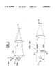
FIG. 1 illustrates a prior art technique of generating holograms. A given temporal-domain optical-pulse data pattern 10 and the optical reference pulse 12 are both dispersed by a diffraction grating 14 located at the input focal plane of a lens 16. The two optical beams carrying these pulses then interact with a permanent recording medium 18 located at the spectrum plane of the lens 16. Such holograms may be used as matched filter to store optical data patterns for subsequent comparison with an incident optical signal to generate an optical correlation signal.
In applying matched filters to signal processing in the time domain, the generation of ultrafast signals, that is, signals having bit rates in the Gigabit to Terabit ranges, require the use of ultrafast optical sources, such as CPM dye lasers and other ultrafast coherent optical sources capable of generating pulses in the femtosecond ranges.
SUMMARY OF THE INVENTION
The present invention facilitates the fabrication of holographic matched filters for application in optical holographic processing of high-speed optical data. The present invention uses the principle that a hologram written by a temporal pattern and a temporal reference pulse is indistinguishable from a hologram written by an appropriately scaled spatial image of the temporal pattern and reference.
By applying time-to-space mappings of such ultrafast signals from the time or temporal domain to the spatial domain, as proposed in M. C. Nuss et al., "Time-to-Space Mapping of Femtosecond Pulses", OPT. LETT, VOL. 19, 1994, pp. 664-666, matched filtering of ultrafast signals may be performed.
This invention generates holographic matched filters by spatially mapping temporal optical pulses in a temporal holography setup. The temporal hologram is recorded by use of a beam from a single-mode diode laser.
In a preferred embodiment, a scaled spatial image of the temporal-domain data is dynamically converted by a spatial light modulator (SLM), which includes a liquid crystal SLM or a multiple quantum well (MQW) p-i-n modulator array and recorded by an erasable MQW photorefractive material or a permanent recording material or other recording media known in the art.
In another preferred embodiment, the scaled spatial image of the temporal data is fixed in an aperture mask, and a permanent recording medium is used.
Matched filters recorded in accordance with the present invention reduce the cost of fabrication of such matched filters for multiplexing and demultiplexing of high-speed optical signals, and for decoding optical signal packet headers by using low-maintenance diode laser elements.
BRIEF DESCRIPTION OF THE DRAWINGS
The features of the disclosed holographic matched filter recording and decoding apparatus and method will become more readily apparent and may be better understood by referring to the following detailed description of an illustrative embodiment of the present invention, taken in conjunction with the accompanying drawings, where:
FIG. 1 is a schematic diagram of matched filter recording in accordance with prior art;
FIG. 2A is a schematic diagram of matched filter recording in accordance with the present invention;
FIG. 2B is a schematic diagram of angle-multiplexed matched filter recording in accordance with the present invention; and
FIG. 3 is a schematic diagram of a real-time femtosecond optical packet header decoder using the hologram recorded by the apparatus shown in FIG. 2B.
DETAILED DESCRIPTION OF THE PREFERRED EMBODIMENT
Referring now in specific detail to the drawings, with like reference numerals identifying similar or identical elements, as shown in FIGS. 2A-2B and 3, the present disclosure describes the recording of a holographic filter for matched filter processing of temporal-domain optical data using an ultrafast optical patterned signal as well as a reference pulse. In recording processes as described in A. M. Weiner et al., "Femtosecond Spectral Holography", IEEE J. QUANT. ELECTR. VOL. 28, NO. 10, 1992, pp. 2251-2261; optical pulses are provided by a CPM dye laser and the signal pulses are crafted using a phase-only mask or SLM inside a femtosecond pulse shaper, as described in A. M. Weiner et al., "High-Resolution Femtosecond Pulse Shaping", J. OPT. SOC. AM. B, VOL. 5, 1988, p. 1563-1572.
FORMATION OF HOLOGRAPHIC MATCHED FILTERS
In contrast to the prior art shown in FIG. 1, the present invention shown in FIGS. 2A-2B provides holographic matched filter recording to record a hologram for matched-filter processing of the temporal-domain data without requiring ultrafast pulsed signal and reference lasers or coherent optical word generators. Such holographic matched filter recording is proposed in commonly owned U.S. application No. 08/177,018, filed Jan. 4, 1994, now abandoned entitled METHOD AND APPARATUS FOR PROCESSING ULTRAFAST OPTICAL SIGNALS, and U.S. application No. 08/339,055 filed Nov. 14, 1994, now U.S. Pat. No. 5,528,389, entitled AN OPTICAL HOLOGRAPHIC SYSTEM FOR PARALLEL TO SERIAL AND SERIAL TO PARALLEL CONVERSION OF OPTICAL DATA, which are incorporated herein by reference.
In the exemplary embodiments disclosed herein, a temporal-domain optical pulse data pattern is first converted into elements of a spatial, amplitude-modulated "fingerprint" light image. This conversion uses the principle that the Fourier spectrum of a spatial pattern is identical to the wavelength spectrum of a temporal pattern when the temporal information is mapped into spatial information by the following scaling law: ##EQU1## where β=λ/d·cos θ is the grating constant, λ is the wavelength of the laser, c is the speed of light, d is the pitch of the grating which is the inverse of the number of lines per millimeter of the grating, and θ is the angle of diffraction as the light emerges from the grating.
An example is shown in FIG. 2A in which a holographic matched filter is written for a 7-bit word "1011011", where each bit is 100 femtoseconds (fs) in duration and the temporal spacing between bits is 300 fs. In the exemplary embodiment, the grating has 600 lines/mm, a diffraction angle θ of 0°, λ=850 nm, and the focal length of the Fourier lens is 200 mm. In the present example, the time-space mapping constant is 1.7 fs/μm, so that the spatial "fingerprint" is equivalent to 3 regions of 60 μm diameter, with a spacing of 180 μm between the regions. Such regions may be circular or square-shaped spots.
This first "fingerprint" image is generated by supplying the spatial pattern 20, scaled from a temporal-domain optical pattern, to a liquid crystal SLM 22 located at the input plane of a Fourier transform lens 24. Such a Fourier lens 24 is a lens having the distance from an input plane to the lens 24 equal to the distance from the lens 24 to the output plane. The SLM 22 dynamically converts or maps the spatial pattern 20 into scaled images or a "fingerprint". In the present example, a SLM 22 with 60 μm pixel size and 200×300 pixels is used. Each 100 fs bit is represented as a single pixel on the SLM 22.
A second "fingerprint" image of the reference pulse signal is provided by an analogous reference pixel 26 and is applied to the liquid crystal SLM 22, as shown in FIG. 2A, at the input plane of the Fourier transform lens 24. The spacing between the reference pixel 26 and spatial pattern 20 on the SLM 22 determines the fringe spacing on the resulting holographic material. For example, if a 10 μm fringe spacing is desired, the spacing between the reference pixel 26 and the spatial pattern 20 is approximately 3 mm, using a Fourier lens having a 200 mm focal length.
These first and second "fingerprint" images are continuously backlit by a monochromatic plane wave beam of light, indicated by the arrowhead 28, from a collimated single-mode diode laser 30 providing 100 mW at 830 nm to produce interference fringe patterns at a recording medium 32 which becomes a hologram.
Preferably, for ultrafast signal processing of femtosecond optical pulses around 850 nm wavelength, the hologram 32 in FIG. 2A is recorded in a GaAs/AlGaAs MQW material with dimensions 0.5 cm×0.5 cm×1 μm, such as described by A. Partovi et al., "Cr-Doped GaAs/AlGaAs Semi-Insulating Multiple Quantum Well Photorefractive Devices", APPL. PHYS. LETT. VOL. 62, NO. 5, 1993, pp. 464-466. The hologram 32 has a response time of less than 2 μs at an energy density of 1 μJ/cm2 and a diffraction efficiency of 3%.
The recording material 32 shown in FIG. 2A may, alternatively, be a thermoplastic or other photorefractive permanent recording medium of similar dimensions; i.e. about 3 mm×3 mm×3 mm, with the size of the hologram being larger than the size of the spectrum of the optical pulses at the spectrum-plane of the instrument. Matched filter recording for temporal-domain optical data signal processing may thus be achieved without the use of ultrafast pulsed and reference lasers. Alternatively, computer-generated holograms, such as binary-phase holograms described in J. Jahns et al., "Dammann Gratings for Laser Beam Shaping", OPT. ENG. VOL. 28, 1989, pp. 1267-1275; may be used. These holograms may be formed by calculating the Fourier-transform of the "image" of the pulses as described above.
It is not a requirement that the wavelength at which the holograms are recorded matches the wavelength used to read out the holograms. This may be particularly advantageous when the response of the hologram is largest at some wavelength other than the readout wavelength, as in the case of Hydrogen-loaded or Germanium-rich glasses, such as described in A. Partovi et al., "Volume Holographic Storage in Hydrogen Treated Germano-Silicate Glass", APPL. PHYS. LETT. VOL. 64, NO. 7, 1994, p. 821-823; or Lithium Niobate photorefractive materials, which are sensitive in the ultraviolet spectral range. In the case of different read and write wavelengths, the time-space scaling factor has to be modified to: ##EQU2## with λw, λr being the write and read wavelengths, respectively, and f the respective focal lengths used for writing and reading the hologram.
AN ALTERNATIVE RECORDING CONFIGURATION
In an alternative exemplary embodiment, the holographic recording apparatus illustrated in FIG. 2B records an angle-multiplexed hologram for a packet header recognition of ultrashort optical pulses in accordance with the present invention, for example, optical pulses of 100 fs duration spaced 300 fs apart. In FIG. 2B, a holographic matched filter is recorded from the interaction of the light emerging from an array 34 of spatially-encoded signal-pulse patterns back-illuminated by a beam 36 illuminating all apertures of array 34 simultaneously.
The back-illuminating beam 36 and a reference light beam 42 are split off from a laser beam 44 from an optical source by a beam splitter 46. The interference between the light emerging from the array mask 34 and the reference beam 42 produces respective interference fringe patterns at the spectrum plane of the Fourier lens 48. These interactions are stored at respective angular orientations within a hologram 50, determined by their relative placement in the spatially-coded bit array mask 34. Holograms generated from such storage of angular orientations of light interactions are referred to as "angle-multiplexed" holograms in the literature.
In the present alternative embodiment, the array 34 is, for example, a primarily opaque 1"×1.5" sheet of glass coated with chromium and etched with openings in the chromium thin film formed, for example, from a lithographic mask. In this example, there are sixteen code blocks set out on 3 mm centers in a square matrix. The "ones" in each code are indicated by circular transparent patches or "pixels" similar to the light apertures provided by the SLM 22 in FIG. 2A. The transparent patches or pixels of the array 34 are illustrated schematically at 52. In the exemplary embodiment, the grating has 600 lines/mm, a diffraction angle θ of 0°, λ=850 nm, and the focal length of the Fourier lens is 200 mm. In this example, five such patches are 60 μm in diameter (1's), and two blanks (0's) are provided at a 180 μm center-to-center spacing within a 3 mm×3 mm portion of the mask 34 and having centers spaced at 3 mm. Images of the bar-shaped transparent patches are Fourier-transformed by the lens 48 and interfere with the reference beam 42 to form the angle-multiplexed hologram 50.
The angle-multiplexed hologram 50 thus recorded is positioned at the spectrum plane of a 200 mm focal length Fourier transform lens 48. In the present alternative embodiment, the sixteen angularly-multiplexed hologram images produced on the hologram 50 by the code patterns in the array 34 may then be used to decode packet headers in pulsed optical communication channels.
DECODING OF PACKET HEADERS
As shown in FIG. 3, a decoding configuration is provided to decode the packet header, where the transmitted optical pulse signal 54 with a bit duration of 100 fs and a bit-to-bit spacing of 300 fs is dispersed by a first reflective diffraction grating 56 having 600 lines/mm and positioned at the input plane of a first Fourier transform lens 58 having a 200 mm focal length. At the spectrum plane of the first Fourier transform lens 58, the wavelength spectrum of the diffracted optical pulse signal 54 is spectrally filtered by a predetermined angle-multiplexed holographic matched filter 60 which may be computer generated. Such spectral filtering produces a beam 62 having an optical correlation peak at the output plane of a second Fourier lens 64 when the code pattern is sufficiently similar enough to produce a detectable correlation peak optical pulse. The beam 62 is back-Fourier-transformed by the second Fourier transform lens 64 having a 200 mm focal length and by the diffraction grating 66. Preferably, the second diffraction grating 66 has 600 lines/mm and is positioned at the output plane of the second Fourier transform lens 64.
In case a match is found, the beam 62 is deflected at an angle determined by the hologram 60 corresponding to the angle between the original pattern and reference beam when the hologram 60 was written.
The diffracted beam 68 from the second diffraction grating 66 is detected by an optical detector array 70, which also determines the angular displacement of the optical correlation pulse to identify the packet header.
While the disclosed holographic matched filter recording and decoding apparatus and method have been particularly shown and described with reference to the preferred embodiments, it will be understood by those skilled in the art that various modifications in form and detail may be made therein without departing from the scope and spirit of the invention. Accordingly, modifications such as those suggested above, but not limited thereto, are to be considered within the scope of the invention.

Claims (26)

What is claimed is:
1. A method for recording a temporal optical pulse pattern in a hologram for time-domain processing of temporal optical data signals, without the need to synthesize the temporal optical signal to be stored, comprising the steps of:
mapping a reference pattern and temporal patterns representing the temporal optical data signals to spatial data patterns using a predetermined time-space scaling law;
providing the spatial data patterns to a spatial light modulator (SLM) to generate scaled spatial signals of the temporal optical data signals;
illuminating the spatial data patterns and pattern with a monochromatic light source;
converting the scaled spatial signals into Fourier transform spectra;
producing interference fringe patterns of the spatial data patterns and reference pattern; and
recording the interference fringe patterns with a holographic recording medium.
2. The method of claim 1 wherein the step of providing includes the step of providing the spatial data patterns to a fixed mask as the SLM.
3. The method of claim 1 wherein the step of providing includes the step of providing the spatial data patterns to a liquid crystal SLM.
4. The method of claim 1 wherein the step of providing includes the step of providing an array of the spatial data patterns to an SLM array.
5. The method of claim 4 wherein the step of providing includes the step of providing the array of spatial data patterns to a fixed mask array.
6. The method of claim 4 wherein the step of providing includes the step of providing the array of spatial data patterns to a liquid crystal SLM array.
7. The method of claim 1 wherein the step of converting includes the step of inputting the scaled spatial signals to a Fourier transform lens.
8. The method of claim 1 wherein the step of producing includes the step of providing the monochromatic light source produced by a collimated single mode diode laser.
9. The method of claim 1 wherein the step of recording the interference fringe patterns includes the step of recording with an erasable multiple quantum well (MQW) structure.
10. The method of claim 1 wherein the step of recording the interference fringe patterns includes the step of recording with a permanent multiple quantum well (MQW) structure.
11. The method of claim 1 wherein the step of mapping includes the step of mapping the temporal optical data signals having a duration of around 100 femtoseconds and spaced at around 300 femtoseconds apart.
12. A method for recording a plurality of temporal optical pulse patterns, without the need to synthesize the temporal optical signals to be stored, comprising the steps of:
mapping a reference pattern and the plurality of temporal optical pulse patterns representing the temporal optical data signal to spatial data patterns using a predetermined time-space scaling law;
providing the spatial data patterns to a spatial light modulator (SLM) to generate scaled spatial signals of the temporal optical data signals, while arranging the plurality of spatial data patterns onto spatially separate regions;
illuminating the plurality of spatial data patterns and the reference pattern with a monochromatic light source;
converting the plurality of scaled spatial signals into Fourier transform spectra having associated angular orientations;
producing a plurality of interference fringe patterns of the spatial data patterns and the reference pattern with distinct spatial carrier frequencies depending on the angular orientations of the respective patterns; and
recording the plurality of interference fringe patterns with a holographic medium.
13. The method of claim 1, wherein the step of illuminating includes the step of providing a back-illuminating beam and a reference light beam split off from a laser beam.
14. A method for recognizing a temporal optical data pattern which was recorded by the steps of mapping a reference pattern and the temporal optical data pattern to spatial data patterns using a predetermined time-space scaling law, providing the spatial data patterns to a spatial light modulator (SLM) to generate scaled spatial signals of the temporal optical data pattern, illuminating the spatial data patterns and reference pattern with a monochromatic light source, converting the scaled spatial signals into Fourier transform spectra, producing interference fringe patterns of the spatial data patterns and reference pattern, and recording the interference fringe patterns with a holographic medium as a recorded temporal optical data pattern, the method comprising the steps of:
dispersing the temporal optical data pattern from the recorded holographic medium;
converting the dispersed temporal optical data pattern to a Fourier transform spectrum;
providing a holographically matched filter storing a plurality of Fourier transform spectra from a plurality of possible data patterns, each one having an associated angular orientation;
comparing the Fourier transform spectrum with the plurality of Fourier transform spectra stored on the holographically matched filter;
outputting an optical correlation signal at an angle determined by the angular orientation of the Fourier transform spectrum stored in the holographic matched filter that most closely matches the Fourier transform spectrum of the temporal optical data pattern; and
recognizing the temporal optical data pattern by detecting the position and the output angle of the optical correlation signal using a detector array that detects the position of the correlation signal.
15. The method of claim 14 wherein the step of converting includes the step of inputting the dispersed temporal optical data pattern to a Fourier transform lens.
16. The method of claim 15 wherein the step of outputting the optical correlation signal includes the steps of:
diffracting the wavelength spectrum signal in response to a match of a code pattern of the wavelength spectrum signal being substantially similar to a holographically stored optical signal of the holographic matched filter to generate a filtered wavelength spectrum signal; and
outputting the filtered wavelength spectrum signal at an angle corresponding to the match as the optical correlation signal.
17. The method of claim 16 wherein the step of comparing includes the step of inputting the filtered wavelength spectrum signal to a Fourier lens and a diffraction grating for back-Fourier-transformation.
18. The method of claim 17 wherein the step of detecting the optical correlation signal includes the step of decoding the optical correlation signal using the optical detector array.
19. The method of claim 18 wherein the step of detecting includes the step of determining an angular displacement of the optical correlation signal to identify a packet header of the input temporal optical data pattern.
20. An apparatus for producing holographic matched filters, comprising:
a spatial-domain modulator for modulating spatial patterns representing temporal optical data signals including a reference signal using a predetermined time-space scaling law;
a holographic recording medium;
a lens for converting the modulated spatial patterns into a Fourier spectrum; and
a monochromatic optical source for optically projecting the converted modulated spatial patterns onto a holographic recording medium to generate a holographic matched filter.
21. The apparatus of claim 20 wherein the holographic recording medium includes a multiple quantum well device.
22. The apparatus of claim 21 wherein the spatial-domain modulator is a liquid crystal spatial light modulator.
23. The apparatus of claim 20 wherein the spatial-domain modulator modulates a plurality of spatial patterns representing a plurality of temporal optical data signals; and
wherein the plurality of converted signals are projected onto the holographic medium to generate the holographic matched filter with multiple signals stored at different angular orientations.
24. An apparatus for producing holographic matched filters for femtosecond optical pulse processing, the apparatus comprising:
a single-mode diode laser emitting a light beam of wavelength λ;
a spatial light, modulator, responsive to input temporal-domain femtosecond optical patterns and input reference patterns, for simultaneous generating corresponding scaled images of the temporal-domain femtosecond optical patterns and reference patterns, respectively, using a predetermined time-space scaling law: ##EQU3## is a time-space scaling factor associated with the spatial light modulator, θ is a diffraction angle associated with the scaled images emitted from the spatial light modulator, c is the speed of light, d is the pitch of the spatial light modulator, λw is a holographic writing wavelength, λr is a holographic reading wavelength, fw is a holographic writing focal length, and fr is a holographic reading focal length;
a Fourier transform lens having the holographic writing focal length fw and positioned at the distance fw from the spatial light modulator with the spatial light modulator being in the input plane of the Fourier transform lens, the Fourier transform lens for converting the scaled images into a Fourier spectrum signal, the Fourier spectrum signal including interference fringe patterns from the simultaneous scaling of both the temporal-domain femtosecond optical patterns and reference patterns; and
a recording medium, composed of GaAs/AlGaAs multiple quantum well material adapted for recording femtosecond optical pulses and disposed at the distance fw from the Fourier transform lens with the recording medium being in the output plane of the Fourier transform lens, the recording medium responsive to the Fourier spectrum signal for recording the interference fringe patterns as a hologram of the temporal-domain femtosecond optical patterns and reference patterns, to generate a holographic matched filter responsive to a monochromatic light source providing a reading light beam having a holographic reading wavelength λr for outputting read-out optical patterns at the holographic reading focal length fr corresponding to the temporal-domain femtosecond optical patterns.
25. An apparatus for producing holographic matched filters, the apparatus comprising:
a light source emitting a light beam of wavelength λ;
scaling means, responsive to input temporal-domain femtosecond optical patterns and input reference patterns, for simultaneous generating corresponding scaled images of the temporal-domain femtosecond optical patterns and reference patterns, respectively, using a predetermined time-space scaling law: ##EQU4## is a time-space scaling factor associated with the scaling means, θ is a diffraction angle associated with the scaled images emitted from the scaling means, c is the speed of light, d is the pitch of the scaling means, λw is a holographic writing wavelength, λr is a holographic reading wavelength, fw is a holographic writing focal length, and fr is a holographic reading focal length;
a Fourier transform lens having the holographic writing focal length fw and positioned at the distance fw from the scaling means, with the scaling means being in the input plane of the Fourier transform lens, the Fourier transform lens for converting the scaled images into a Fourier spectrum signal, the Fourier spectrum signal including interference fringe patterns from the simultaneous scaling of both the temporal-domain femtosecond optical patterns and reference patterns; and
a recording medium adapted for recording femtosecond optical pulses and disposed at the distance fw from the Fourier transform lens with the recording medium being in the output plane of the Fourier transform lens, the recording medium responsive to the Fourier spectrum signal for recording the interference fringe patterns as a hologram of the temporal-domain femtosecond optical patterns and reference patterns, to generate a holographic matched filter responsive to a monochromatic light source providing a reading light beam having a holographic reading wavelength λr for outputting read-out optical patterns at the holographic reading focal length fr corresponding to the temporal-domain femtosecond optical patterns.
26. The apparatus of claim 25 wherein the scaling means is a grating having the pitch d=1/600 mm, which is the inverse of the number of lines per millimeter of the grating, for facilitating femtosecond optical pulse processing.
US08/608,972 1994-01-04 1996-02-28 Method and apparatus and for processing ultrafast optical signals Expired - Fee Related US5668647A (en)

Priority Applications (1)

Application Number Priority Date Filing Date Title
US08/608,972 US5668647A (en) 1994-01-04 1996-02-28 Method and apparatus and for processing ultrafast optical signals

Applications Claiming Priority (3)

Application Number Priority Date Filing Date Title
US17701894A 1994-01-04 1994-01-04
US33891294A 1994-11-14 1994-11-14
US08/608,972 US5668647A (en) 1994-01-04 1996-02-28 Method and apparatus and for processing ultrafast optical signals

Related Parent Applications (1)

Application Number Title Priority Date Filing Date
US33891294A Continuation 1994-01-04 1994-11-14

Publications (1)

Publication Number Publication Date
US5668647A true US5668647A (en) 1997-09-16

Family

ID=26872847

Family Applications (1)

Application Number Title Priority Date Filing Date
US08/608,972 Expired - Fee Related US5668647A (en) 1994-01-04 1996-02-28 Method and apparatus and for processing ultrafast optical signals

Country Status (1)

Country Link
US (1) US5668647A (en)

Cited By (5)

* Cited by examiner, † Cited by third party
Publication number Priority date Publication date Assignee Title
US6025950A (en) * 1997-09-22 2000-02-15 Coretek, Inc. Monolithic all-semiconductor optically addressed spatial light modulator based on low-photoconductive semiconductors
US20040175184A1 (en) * 2002-10-15 2004-09-09 Communications Res. Lab., Ind. Admin. Inst. Method and apparatus for decoding digital signal
US6819460B1 (en) * 1995-03-13 2004-11-16 University Of Washington Apparatus and methods for routing of optical beams via time-domain spatial-spectral filtering
US20080144473A1 (en) * 2005-08-11 2008-06-19 Fujitsu Limited Optical element and optical information recording/reproducing apparatus
CN115268200A (en) * 2022-08-10 2022-11-01 武汉大学 Multi-frame ultrafast phase imaging system and method

Citations (13)

* Cited by examiner, † Cited by third party
Publication number Priority date Publication date Assignee Title
US3608992A (en) * 1970-06-18 1971-09-28 Ncr Co Multiplex holography with tresnel diffraction pattern coded reference beans
US3612641A (en) * 1969-01-23 1971-10-12 Int Standard Electric Corp Holographic data storage with an orthogonally coded reference beam
US3899240A (en) * 1965-08-13 1975-08-12 Ibm Method for distinguishing similar subjects using discriminating holograms
US4339176A (en) * 1980-05-19 1982-07-13 Honeywell Inc. Holographic space-variant system for evaluating the ambiguity integral
US4948212A (en) * 1988-08-22 1990-08-14 California Institute Of Technology Optical processing in III-V and II-VI compound semiconductors
US4971409A (en) * 1989-04-24 1990-11-20 Rockwell International Corporation Real-time optical image subtraction
US5004325A (en) * 1990-01-16 1991-04-02 At&T Bell Laboratories Optical processing using a multilayer heterostructure
US5080464A (en) * 1989-09-05 1992-01-14 Hamamatsu Photonics K.K. Optical neural network apparatus using primary processing
US5103324A (en) * 1990-05-22 1992-04-07 Grumman Aerospace Corporation Method for fabricating holographic filters
US5150229A (en) * 1988-09-07 1992-09-22 Seiko Instruments Inc. Optical correlator
US5150228A (en) * 1991-11-25 1992-09-22 The United States Of America As Represented By The Administrator Of The National Aeronautics And Space Administration Real-time edge-enhanced optical correlator
US5216529A (en) * 1992-01-15 1993-06-01 Bell Communications Research, Inc. Holographic code division multiple access
US5274716A (en) * 1990-09-05 1993-12-28 Seiko Instruments Inc. Optical pattern recognition apparatus

Patent Citations (14)

* Cited by examiner, † Cited by third party
Publication number Priority date Publication date Assignee Title
US3899240A (en) * 1965-08-13 1975-08-12 Ibm Method for distinguishing similar subjects using discriminating holograms
US3612641A (en) * 1969-01-23 1971-10-12 Int Standard Electric Corp Holographic data storage with an orthogonally coded reference beam
US3608992A (en) * 1970-06-18 1971-09-28 Ncr Co Multiplex holography with tresnel diffraction pattern coded reference beans
US4339176A (en) * 1980-05-19 1982-07-13 Honeywell Inc. Holographic space-variant system for evaluating the ambiguity integral
US4948212A (en) * 1988-08-22 1990-08-14 California Institute Of Technology Optical processing in III-V and II-VI compound semiconductors
US5150229A (en) * 1988-09-07 1992-09-22 Seiko Instruments Inc. Optical correlator
US4971409A (en) * 1989-04-24 1990-11-20 Rockwell International Corporation Real-time optical image subtraction
US5080464A (en) * 1989-09-05 1992-01-14 Hamamatsu Photonics K.K. Optical neural network apparatus using primary processing
US5004325A (en) * 1990-01-16 1991-04-02 At&T Bell Laboratories Optical processing using a multilayer heterostructure
US5103324A (en) * 1990-05-22 1992-04-07 Grumman Aerospace Corporation Method for fabricating holographic filters
US5274716A (en) * 1990-09-05 1993-12-28 Seiko Instruments Inc. Optical pattern recognition apparatus
US5150228A (en) * 1991-11-25 1992-09-22 The United States Of America As Represented By The Administrator Of The National Aeronautics And Space Administration Real-time edge-enhanced optical correlator
US5216529A (en) * 1992-01-15 1993-06-01 Bell Communications Research, Inc. Holographic code division multiple access
US5289299A (en) * 1992-01-15 1994-02-22 Bell Communications Research, Inc. Holographic code division multiple access

Non-Patent Citations (18)

* Cited by examiner, † Cited by third party
Title
A. Partovi et al., "Cr-Doped GaAs/AlGaAs Semi-Insulating Multiple Quantum Well Photorefractive Devices", Appl. Phys. Lett. vol. 62, No. 5, 1993, pp. 464-466. No Month.
A. Partovi et al., "Volume Holographic Storage in Hydrogen Treated Germano-Silicate Glass", Appl. Phys. Lett. vol. 64, No. 7, 1994, pp. 821-823. No Month.
A. Partovi et al., Cr Doped GaAs/AlGaAs Semi Insulating Multiple Quantum Well Photorefractive Devices , Appl. Phys. Lett. vol. 62, No. 5, 1993, pp. 464 466. No Month. *
A. Partovi et al., Volume Holographic Storage in Hydrogen Treated Germano Silicate Glass , Appl. Phys. Lett. vol. 64, No. 7, 1994, pp. 821 823. No Month. *
A.M. Weiner et al., "Femtosecond Spectral Holography", IEEE Journal of Quantum Electronics, vol. 28, No. 10, Oct. 1992, pp. 2251-2261.
A.M. Weiner et al., "High-Resolution Femtosecond Pulse Shaping", J. Opt. Soc. Am. B, vol. 5, 1988, pp. 1563-1572. No Month.
A.M. Weiner et al., "Programmable Shaping of Femtosecond Optical Pulses by Use of 128-Element Liquid Crystal Phase Modulator", IEEE J. Quant. Electr. vol. 28, No. 4, 1992, pp. 909-920. No Month.
A.M. Weiner et al., Femtosecond Spectral Holography , IEEE Journal of Quantum Electronics, vol. 28, No. 10, Oct. 1992, pp. 2251 2261. *
A.M. Weiner et al., High Resolution Femtosecond Pulse Shaping , J. Opt. Soc. Am. B, vol. 5, 1988, pp. 1563 1572. No Month. *
A.M. Weiner et al., Programmable Shaping of Femtosecond Optical Pulses by Use of 128 Element Liquid Crystal Phase Modulator , IEEE J. Quant. Electr. vol. 28, No. 4, 1992, pp. 909 920. No Month. *
J. Jahns et al., "Dammann Gratings for Laser Beam Shaping", Opt. Eng. vol. 28, 1989, pp. 1267-1275. No Month.
J. Jahns et al., Dammann Gratings for Laser Beam Shaping , Opt. Eng. vol. 28, 1989, pp. 1267 1275. No Month. *
K. Smith et al., "All-Optical Clock Recovery Using a Mode-Locked Laser", Electronics Lett., vol. 28, No. 19, Sep. 1992, pp. 1814-1816.
K. Smith et al., All Optical Clock Recovery Using a Mode Locked Laser , Electronics Lett., vol. 28, No. 19, Sep. 1992, pp. 1814 1816. *
M.C. Nuss et al., "Time-to-Space Mapping of Femtosecond Pulses", Opt. Lett, vol. 19, 1994, pp. 664-666. No Month.
M.C. Nuss et al., Time to Space Mapping of Femtosecond Pulses , Opt. Lett, vol. 19, 1994, pp. 664 666. No Month. *
T.K. Woodward et al., "GaAs/AlGaAs FET-SEED Receiver/Transmitters", Osa Proc. on Photonics in Switching, vol. 16, 1993, pp. 89-93. No Month.
T.K. Woodward et al., GaAs/AlGaAs FET SEED Receiver/Transmitters , Osa Proc. on Photonics in Switching, vol. 16, 1993, pp. 89 93. No Month. *

Cited By (7)

* Cited by examiner, † Cited by third party
Publication number Priority date Publication date Assignee Title
US6819460B1 (en) * 1995-03-13 2004-11-16 University Of Washington Apparatus and methods for routing of optical beams via time-domain spatial-spectral filtering
US6025950A (en) * 1997-09-22 2000-02-15 Coretek, Inc. Monolithic all-semiconductor optically addressed spatial light modulator based on low-photoconductive semiconductors
US20040175184A1 (en) * 2002-10-15 2004-09-09 Communications Res. Lab., Ind. Admin. Inst. Method and apparatus for decoding digital signal
US7423793B2 (en) * 2002-10-15 2008-09-09 National Institute Of Information And Communication Technology Method and apparatus for decoding digital signal
US20080144473A1 (en) * 2005-08-11 2008-06-19 Fujitsu Limited Optical element and optical information recording/reproducing apparatus
CN115268200A (en) * 2022-08-10 2022-11-01 武汉大学 Multi-frame ultrafast phase imaging system and method
CN115268200B (en) * 2022-08-10 2023-07-21 武汉大学 Multi-frame ultrafast phase imaging system and method

Similar Documents

Publication Publication Date Title
US6154432A (en) Optical storage system
US4988153A (en) Holographic memory read by a laser array
US6710901B2 (en) Method and apparatus for two-photon, volumetric spatially resolved holographic data storage in photosensitive glass
JP2002319285A (en) Self-referenced holographic storage device
US7200097B2 (en) Parallel recording and reading of diffractive memory using multiple object beams
JP2004253121A (en) Self-referenced holography using diffusive element
KR100354798B1 (en) System and method for holographic storage using a holographic optical element
US5668647A (en) Method and apparatus and for processing ultrafast optical signals
EP0713107A2 (en) Method and apparatus for processing ultrafast optical signals
WO2005066724A1 (en) Holographic multiple recording method, holographic recording device using the same, and holographic recording medium
US5528389A (en) Optical holographic system for parallel to serial and serial to parallel conversion of optical data
US7248556B2 (en) Fast duplication of diffractive storage device for mass production
JP3083111B2 (en) Optical data pulse train generation method
KR20000077127A (en) System and method for controlling the selectivity of a holographic memory system
JP3416976B2 (en) Phase mask and phase mask reproducing apparatus
JPH07219415A (en) Method and apparatus for generation of holography-matched filter
JPH05181404A (en) Method and device for hologram recording
AU701056B2 (en) Optical storage system
KR100275277B1 (en) Volume holographic digital data storage system using reflection
Timuçin et al. Holographic optical data storage
KR100275275B1 (en) Volume holographic digital data storage system using total reflection
Lal et al. Laser-diode-based joint transform correlator for fingerprint identification
JPH0659383A (en) Optical memory
KR20000040904A (en) Hologram memory multi coping system
KR100278067B1 (en) Volume holographic digital data storage system

Legal Events

Date Code Title Description
FEPP Fee payment procedure

Free format text: PAYOR NUMBER ASSIGNED (ORIGINAL EVENT CODE: ASPN); ENTITY STATUS OF PATENT OWNER: LARGE ENTITY

FPAY Fee payment

Year of fee payment: 4

AS Assignment

Owner name: THE CHASE MANHATTAN BANK, AS COLLATERAL AGENT, TEX

Free format text: CONDITIONAL ASSIGNMENT OF AND SECURITY INTEREST IN PATENT RIGHTS;ASSIGNOR:LUCENT TECHNOLOGIES INC. (DE CORPORATION);REEL/FRAME:011722/0048

Effective date: 20010222

FPAY Fee payment

Year of fee payment: 8

AS Assignment

Owner name: LUCENT TECHNOLOGIES INC., NEW JERSEY

Free format text: TERMINATION AND RELEASE OF SECURITY INTEREST IN PATENT RIGHTS;ASSIGNOR:JPMORGAN CHASE BANK, N.A. (FORMERLY KNOWN AS THE CHASE MANHATTAN BANK), AS ADMINISTRATIVE AGENT;REEL/FRAME:018584/0446

Effective date: 20061130

REMI Maintenance fee reminder mailed
LAPS Lapse for failure to pay maintenance fees
STCH Information on status: patent discontinuation

Free format text: PATENT EXPIRED DUE TO NONPAYMENT OF MAINTENANCE FEES UNDER 37 CFR 1.362

FP Lapsed due to failure to pay maintenance fee

Effective date: 20090916