US5664213A - Input/output (I/O) holdoff mechanism for use in a system where I/O device inputs are fed through a latency introducing bus - Google Patents
Input/output (I/O) holdoff mechanism for use in a system where I/O device inputs are fed through a latency introducing bus Download PDFInfo
- Publication number
- US5664213A US5664213A US08/504,936 US50493695A US5664213A US 5664213 A US5664213 A US 5664213A US 50493695 A US50493695 A US 50493695A US 5664213 A US5664213 A US 5664213A
- Authority
- US
- United States
- Prior art keywords
- deserializer
- request
- bus
- controller
- signal
- Prior art date
- Legal status (The legal status is an assumption and is not a legal conclusion. Google has not performed a legal analysis and makes no representation as to the accuracy of the status listed.)
- Expired - Lifetime
Links
Images


Classifications
-
- G—PHYSICS
- G06—COMPUTING; CALCULATING OR COUNTING
- G06F—ELECTRIC DIGITAL DATA PROCESSING
- G06F13/00—Interconnection of, or transfer of information or other signals between, memories, input/output devices or central processing units
- G06F13/14—Handling requests for interconnection or transfer
- G06F13/20—Handling requests for interconnection or transfer for access to input/output bus
- G06F13/32—Handling requests for interconnection or transfer for access to input/output bus using combination of interrupt and burst mode transfer
-
- G—PHYSICS
- G06—COMPUTING; CALCULATING OR COUNTING
- G06F—ELECTRIC DIGITAL DATA PROCESSING
- G06F13/00—Interconnection of, or transfer of information or other signals between, memories, input/output devices or central processing units
- G06F13/38—Information transfer, e.g. on bus
- G06F13/382—Information transfer, e.g. on bus using universal interface adapter
- G06F13/385—Information transfer, e.g. on bus using universal interface adapter for adaptation of a particular data processing system to different peripheral devices
-
- G—PHYSICS
- G06—COMPUTING; CALCULATING OR COUNTING
- G06F—ELECTRIC DIGITAL DATA PROCESSING
- G06F13/00—Interconnection of, or transfer of information or other signals between, memories, input/output devices or central processing units
- G06F13/38—Information transfer, e.g. on bus
- G06F13/42—Bus transfer protocol, e.g. handshake; Synchronisation
- G06F13/4204—Bus transfer protocol, e.g. handshake; Synchronisation on a parallel bus
- G06F13/4221—Bus transfer protocol, e.g. handshake; Synchronisation on a parallel bus being an input/output bus, e.g. ISA bus, EISA bus, PCI bus, SCSI bus
- G06F13/423—Bus transfer protocol, e.g. handshake; Synchronisation on a parallel bus being an input/output bus, e.g. ISA bus, EISA bus, PCI bus, SCSI bus with synchronous protocol
Definitions
- the present invention generally relates to electronic input/output (I/O) systems and methods, and, more specifically, relates to an I/O holdoff mechanism for use in a system where I/O device inputs are fed through a latency introducing bus.
- I/O electronic input/output
- VL82C480 chipset by VLSI Technology, Inc.
- ISA Industry Standard Architecture
- the VL82C480 put the direct memory access (DMA) Request (DRQ) and Interrupt Request (IRQ) inputs that service the ISA bus into a parallel to serial converter, and used the resulting serial stream to determine the state of the DRQ and IRQ inputs.
- DMA direct memory access
- DRQ direct memory access
- IRQ Interrupt Request
- This serial stream had a dedicated bit for each DRQ and IRQ input, making for a large serial packet. In essence, the serial stream provides a series of snapshot of the state of all the pins in the system.
- This method of serialization of DRQs and IRQs introduces latency to these signals due to the time required to serialize the data, the time required to shift out this large serial packet, and the time required to convert this serial data back to parallel format.
- a DMA Request excessive latency could result in the DRQ input being asserted after the service of the DMA is no longer required, resulting in overflowing or underflowing the DMA data transfer.
- an Interrupt Request excessive latency could cause the IRQ input to be asserted when an interrupt is no longer present, resulting in the CPU serving the Interrupt Request needlessly. For these reasons the latency of the serial stream is critical and must be minimized.
- a system in which an I/O holdoff mechanism is used to compensate for I/O device inputs being fed through a latency introducing bus.
- the system includes one or more I/O devices connected through a serial bus to a controller device.
- Each I/O device includes at least one request pin which is connected to a peripheral device.
- the I/O device responds to a voltage transition occurring on any request pin of the I/O device by forwarding, in a packet over the serial bus, an indicator.
- the indicator indicates a current voltage value on the request pin of the I/O device on which the voltage transition occurred.
- the controller device includes a deserializer and a bus controller.
- the deserializer receives the first packet and outputs a signal which indicates a current value for a voltage on the indicated request pin.
- the deserializer includes a busy output which indicates when the deserializer is busy and when the deserializer is idle.
- the bus controller responds to a request from a host system for the current value on a first request pin of the I/O device by forwarding to the host system a current value for a voltage on the indicated request pin, as indicated by the deserializer, when the deserializer is not busy.
- the bus controller When the deserializer is busy, the bus controller responds to the request from the host system for the current value on the first request pin of the I/O device by waiting for the deserializer to become idle. Upon the deserializer becoming idle, the bus controller forwards to the host system the current value for the voltage on the indicated request pin.
- the controller device includes wait state assertion logic.
- the wait state assertion logic prevents the bus controller from forwarding to the host system the current value for the voltage on the indicated request pin when the deserializer when the deserializer is busy.
- this embodiment is used when an I/O bus connected between the controller device and the host system operates in accordance with the ISA bus standard.
- the controller device includes a latency counter which is, for example, located inside the deserializer.
- the bus controller responds to the request from the host system for the current value on the first request pin of the I/O device, by starting the counter.
- the counter when started, issues a finished signal when the counter has counted a sufficient mount of dock cycles to allow any voltage transition occurring on any request pin of the I/O device to result in a signal being generated by the deserializer.
- the counter is started, upon the counter issuing the finished signal or upon the deserializer becoming idle, whichever first occurs, the current value for the voltage on the indicated request pin is forwarded to the host system.
- this embodiment is used when an I/O bus connected between the controller device and the host system operates in accordance with the Peripheral Component Interconnect (PCI) bus standard as described in the PCI 2.1 specification.
- PCI Peripheral Component Interconnect
- the controller device operates in two modes. In a first mode, the deserializer periodically is in an idle state. In a second mode, the deserializer never enters the idle state. When the controller device is operating in the second mode, the bus controller forwards the current value for the voltage on the indicated request pin to the host system upon the counter issuing the finished signal.
- PCI Peripheral Component Interconnect
- the present invention is useful in systems in which an I/O device interrupts or other information are passed to a controlling device by a serial bus/link.
- the present invention prevents system errors which could arise from latency of packet transfers affecting programs which depend on seeing real-time signal values at an IJO controller and/or a DMA controller.
- FIG. 1 shows a simplified block diagram of a system in which the rising and falling edges of signals on request pins are detected and serialized in accordance with a preferred embodiment of the present invention.
- FIG. 2 shows a block diagram of a personal computer I/O system in which the rising and falling edges of interrupt and DMA request signals are detected and serialized, in accordance with a preferred embodiment of the present invention.
- FIG. 3 is a timing diagram showing the timing sequence for serializing a DMA request for the system of FIG. 2.
- FIG. 4 is a timing diagram showing the timing sequence for serializing an interrupt request for the system of FIG. 2.
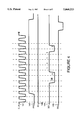
- FIG. 5 is a timing diagram showing the timing sequence for serializing an interrupt request for the system of FIG. 2 when the serial bus is busy with a DMA request.
- FIG. 6 shows a simplified block diagram of a system in which the rising and falling edges of signals on request pins are detected and serialized in accordance with an alternate preferred embodiment of the present invention.
- FIG. 7 shows a logic diagram for wait state assertion logic in accordance with a preferred embodiment of the present invention.
- FIG. 1 shows a simplified block diagram of a system in which the rising and falling edges of interrupt signals are detected and serialized in accordance with a preferred embodiment of the present invention.
- a device 34 is connected through a serial bus connection 52 to a device 32.
- Device 32 is likewise connected to a device 30 through a serial bus connection 51.
- the signal placed on a request pin 55 by a peripheral device 58 is encoded by a pin encode control 50 within a serializer 49.
- the signal on request pin 55 is an interrupt request or a DMA request.
- serializer 49 sends a packet with the edge infomarion through serial bus connection 52 to device 32.
- Device 32 sends the packet through 51 on to device 30.
- Device 34 may have other request pins, the signals on which are encoded by additional pin encode controls.
- the signal placed on a request pin 54 by a peripheral device 57 is encoded by a pin encode control 47 within a serializer 46.
- the signal on request pin 54 is an interrupt request or a DMA request.
- serializer 46 sends a packet with the edge information through serial bus connection 51 to device 30.
- the signal placed on a request pin 53 by a peripheral device 58 is encoded by a pin encode control 48 within serializer 46.
- the signal on request pin 53 is an interrupt request or a DMA request.
- serializer 46 sends a packet with the edge information through serial bus connection 51 to device 30.
- Device 34 may have other request pins, the signals on which are encoded by additional pin encode controls.
- Device 30 includes various controllers.
- FIG. 1 shows device 30 to include an interrupt controller 41 and a DMA controller 42.
- Deserializer 43 deserializes packet information received by device 30 over serial bus connection 51. For example, packets indicating a transition of an interrupt request signal are received by pin emulate control 44. Pin emulate control 44 produces an emulated interrupt request signal and forwards the emulated interrupt request signal to interrupt controller 41. Edge transitions of the emulated interrupt request signal are based on the packets device 30 receives over serial bus connection 51.
- Pin emulate control 45 produces an emulated DMA request signal and forwards the emulated interrupt request signal to DMA controller 42. Edge transitions of the emulated DMA request signal are based on the packets device 30 receives over serial bus connection 51.
- a bus controller 22 is used by a host system to control a read of the IRQ signals received by interrupt controller 41 and DRQ signals received by DMA controller 42 onto bus data lines 25 of an I/O bus.
- the data bus operates in accordance with the ISA bus standard and bus controller 22 is an ISA sequencer. Alternately, other types of data buses may be utilized.
- the data bus may operate in accordance with the Peripheral Component Interconnect (PCI) bus standard as described in the PCI 2.1 specification.
- PCI Peripheral Component Interconnect
- Bus controller 22 controls a read from interrupt controller 41 using I/O read lines 27.
- Bus controller 22 controls a read from DMA controller 42 using I/O read lines 28.
- Bus controller 22 is directed by the host system to perform reads to interrupt controller 41 and DMA controller 42 by control information placed on control lines 24 of the I/O bus.
- bus controller 22 When directed by the control information placed on control lines 24, bus controller 22 will initiate a read from interrupt controller 41 by asserting a chip select for interrupt controller 41 and asserting an I/O read line. Using two address lines, bus controller 22 will indicate to interrupt controller 41 which register is to be read. Bus controller 22 will not complete the I/O read until it receives an I/O channel ready signal on line 23 of the I/O bus.
- the I/O channel ready signal on line 23 of the I/O bus is intercepted by wait state assertion logic 21.
- wait state assertion logic 21 will keep the I/O channel ready signal on a line 26 de-asserted to bus controller 22 as long as a busy signal on line 29 from deserializer 43 is asserted.
- Deserializer 43 asserts the busy signal on line 29 as long as deserializer 43 is receiving packets from serial bus 51.
- serial bus 51 goes idle, deserializer 43 de-asserts the busy signal on line 29.
- wait state assertion logic 21 asserts the I/0 channel ready signal to bus controller 22 on a line 26. Bus controller 22 then completes the data transaction over the I/O bus.
- bus controller 22 when directed by control information placed on control lines 24, bus controller 22 will initiate a read from DMA controller 42 by asserting a chip select for DMA controller 42 and asserting an I/O read line. Using two address lines, bus controller 22 will indicate to DMA controller 42 which register is to be read. Bus controller 22 will not complete the I/O read until it receives the I/O channel ready signal on line 23 of the I/O bus. The I/O channel ready signal on line 23 of the//0 bus is intercepted by wait state assertion logic 21.
- wait state assertion logic 21 will keep the I/O channel ready signal on line 26 de-asserted to bus controller 22 as long as a busy signal on line 29 from deserializer 43 is asserted.
- Deserializer 43 asserts the busy signal on line 29 as long deserializer 43 is receiving packets from serial bus 51.
- serial bus 51 goes idle, deserializer 43 de-asserts the busy signal on line 29.
- wait state assertion logic 21 will assert the I/O channel ready signal to bus controller 22 on line 26. Bus controller 22 then completes the data transaction over the I/O bus.
- Wait state assertion logic 21 is utilized to compensate for any latency in transfer of IRQ/DRQ pin values through serial bus 51 to deserializer 43.
- This latency is caused, for example, by the simultaneous transition of several IRQ signals or DRQ signals.
- the latency could result in system failure in the case where a program running on the host system is utilizing real-time values of IRQ signals and/or DRQ signals. For example, if the host system requires a real-time value and because of latency the host system accesses the information before the latest value arrives via the serial bus, the host system will have accessed a stale value.
- IRQ/DRQ signals can be obtained by the host system from interrupt controller 41 or DMA controller 42 utilizing bus controller 22.
- bus controller 22 By holding up any read of IRQ values or DRQ values over the IYO bus until serial bus 51 goes idle, the real-time the IRQ values and DRQ values are obtained by the read over the I/O bus.
- FIG. 7 shows logic which implements wait state assertion logic 21.
- the logic includes, for example, a logic AND gate 161, a logic AND gate 162 and a logic NOR gate 163 connected as shown.
- FIG. 2 provides an example of a specific system which utilizes the present invention.
- a system controller 60 a peripheral controller 62, and four identical I/O devices 64, 66, 68 and 70 known as EXCA controllers are shown.
- Each of devices 60, 62, 64, 66, 68, and 70 has a clock input (CLK) which is connected to a common clock source 71.
- CLK clock input
- Each of devices 62, 64, 66, 68, and 70 has at least one dedicated acknowledgment signal (DAK) line connected to system controller 60.
- DAK lines are collectively labeled as lines 73 on FIG. 2.
- System controller 60 makes an acknowledgment to a particular device by asserting an acknowledgment signal (DAK) on the DAK line from DAK lines 73 which is connected to the particular device.
- DAK acknowledgment signal
- each of devices 60, 62, 64, 66, 68, and 70 has a reset input (RST) which is connected to a common system reset signal 72.
- RST reset input
- System controller 60 corresponds to a CPU chipset, which includes an internal interrupt controller (not shown) and an internal DMA controller (not shown).
- EXCA controllers 64, 66, 68 and 70 are expansion slots for peripherals such as random access memory (RAM), a modem, serial and parallel communication ports, etc.
- EXCA controller 64 receives DMA requests from a first peripheral on a DRQ pin 91 and receives IRQ interrupt requests from the first peripheral on an IRQ pin 92.
- EXCA controller 66 receives DMA requests from a second peripheral on a DRQ pin 93 and receives IRQ interrupt requests from the second peripheral on an IRQ pin 94.
- EXCA controller 68 receives DMA requests from a third peripheral on a DRQ pin 95 and receives IRQ interrupt requests from the third peripheral on an IRQ pin 96.
- EXCA controller 70 receives DMA requests from a fourth peripheral on a DRQ pin 97 and receives IRQ interrupt requests from the fourth peripheral on an IRQ pin 98.
- Peripheral controller 62 is used to encode interrupt request (IRQ) information on IRQ pins 100 and DMA request (DRQ) information on DRQ pins 101 relating to an ISA bus 101, and to pass along serial data from EXCA controllers 64, 66, 68 and 70 to system controller 60.
- IRQ interrupt request
- DRQ DMA request
- the serial in port (SI) to EXCA controller 64 is connected to a ground 80, and thus held to a constant low logic state.
- the serial out port (SO) of EXCA controller 64 is connected through a serial bus connection 81 to the serial in port of EXCA controller 66.
- the serial out port of EXCA controller 66 is connected through a serial bus connection 82 to the serial in port of EXCA controller 68, and the serial out port of EXCA controller 68 is connected through a serial bus connection 83 to the serial in port of EXCA controller 70.
- serial out port of EXCA controller 70 is connected through a serial bus connection 84 to the serial in port of peripheral controller 62, and the serial out port of peripheral controller 62 is connected through a serial bus connection 85 to the serial in port of system controller 60.
- serial bus connections 81 through 85 provide daisy-chain connections from one device to the next and together form a serial bus.
- the serial bus interconnects the devices of FIG. 2 as shown, providing a data path for EXCA controllers 64, 66, 68 and 70, and peripheral controller 62, to communicate with system controller 60.
- this serial bus provides a low pin count solution for providing programmable interrupt requests (IRQ) and DMA requests (DRQ) for the peripherals coupled to EXCA controllers 64, 66, 68 and 70.
- IRQ programmable interrupt requests
- DRQ DMA requests
- the serial bus also allows the interrupts and DMA requests from other ISA bus peripherals to be located remotely from the DMA controller and interrupt controller within system controller 60, by coupling the IRQ and DRQ lines from the ISA Bus to peripheral controller 62 as shown.
- the serial bus encodes system management interrupt (SMI), IRQ, and DRQ information in a six bit packet and transmits this information serially to peripheral controller 62.
- the serial bus protocol provides for daisy chaining multiple interrupt request and DMA request sources together on a single serial stream, further minimizing the pin overhead for IRQ and DRQ support. This scheme allows multiple I/O devices to use the same IRQ level or DRQ level without these sources directly driving the same IRQ or DRQ signals.
- the serial bus uses defined packets to transfer data. Each packet contains six bits of information that is equivalent to one signal in a typical ISA bus implementation.
- the packet can be either an interrupt request (IRQ), a DMA request (DRQ), an SMI request, or an EXCA controller number, as shown in Table 1 below.
- the first bit is a start bit.
- the next two bits are a packet type field which identifies the type of data being sent.
- the four remaining bits are packet identification (ID), identifying the packet. Note that an optional stop bit is also included if the serial data bus is idle following the packet.
- the serial bus is a synchronous serial bus, with all packets transmitted synchronously to the dock from common dock source 71. Data changes on the rising edge of the dock from common dock source 71.
- Each device 62, 64, 66, 68 and 70 on the serial bus samples data presented to its serial in port on the falling edge of the clock from common dock source 71, and resynchronizes the incoming data stream before passing it on. This introduces one clock cycle of latency for each I/O device on the serial bus, but guarantees that the data stream will always be synchronous to the clock from common clock source 71, regardless of the number of devices on the serial bus.
- Common dock source 71 can be provided from an external source as shown in FIG. 2, or may be generated in one of the serial bus devices and connected to the remaining devices.
- the dock from common clock source 71 is typically a 25 MHz square wave in this particular example, but there is no minimum clock frequency requirement.
- the clock from common clock source 71 can be any frequency providing the latency on the serial bus is not so great that reliable system operation is impaired.
- a packet with a Packet type 11 is used to indicate the edge information for the DMA requests or the interrupt requests.
- the first three bits [5:3] of the packet ID are used to indicate the DMA level. This is possible because in the preferred embodiment there are only eight DMA request levels which may be identified using bits [5:3].
- the sixth bit of the Packet ID contains the edge information. A positive edge is indicated by a 0 and a negative edge is indicated by a 1.
- IRQ interrupt requests
- All of bits [6:3] of the Packet ID are used to identify the interrupt level, therefore, a packet with a packet type 00 is used to indicate a negative edge in the interrupt request.
- a packet with a Packet type 10 is used to indicate a positive edge or a pulse in the interrupt request.
- a pulse is indicated when a second packet with packet type 10 is received without an intervening negative edge IRQ packet (Packet Type 00) being received.
- the arbitration algorithm is as follows. The position of an I/O device in the daisy chain determines the priority of the I/O device. The higher an I/O device is on the daisy chain (i.e., the farther away from system controller 60), the higher the priority.
- Start bits for each I/O device are always a modulo 7 number of clock cycles apart. This allows each device on the serial bus to determine when it is allowed to start transmission of a packet. Since the higher priority devices are placed higher in the chain, they will keep the serial bus busy when they require service, effectively locking out lower priority devices which are lower down the chain until the serial bus goes inactive. Since a stop bit only occurs if there is no packet immediately following the current packet, a stop bit signals the I/O device receiving it that the serial bus is available for it to transmit a packet, if needed. Given the one clock cycle latency for each I/O device caused by resynchronizing incoming data to the clock from common clock source 71, an I/O device can sense a stop bit, and begin transmitting its packet on the very next clock cycle.
- each I/O device counts the number of successive ones received on its serial in port. When the count of ones exceeds six, the I/O device knows than an empty packet has just occurred, and the I/O device will synchronize itself to the next zero bit since it is, by definition, a start bit.
- the serial bus can be used to transfer information regarding interrupt requests (including IRQ and SMI requests) and DMA requests from each EXCA controller, as well as configuring the EXCA controllers 64, 66, 68 and 70 to their respective assigned address spaces.
- the present invention relates to the serialization of IRQ, SMI and DRQ signals.
- An EXCA controller transmits Packet Type 01 when it requires SMI service from system controller 60, transmits Packet Type 60 when it requires Interrupt Request service from system controller 60, and transmits a Packet Type 11 when it requires service from the DMA controller within system controller 60.
- Packet type 00 is used to configure the EXCA controllers 64, 66, 68 and 70 upon system reset or power-up. After start-up, the Packet type 00 is used to indicate an IRQ negative edge.
- the operation of the system as shown in FIGS. 3 through 5 assumes that the system has been reset, and that the EXCA controllers 64, 66, 68 and 70 have all been configured to their unique address spaces.
- FIG. 3 The timing of the serialization of a typical DMA Request for the system of FIG. 2 is shown in FIG. 3.
- This particular example assures that the first peripheral, which is connected to EXCA controller 64 (see FIG. 2), desires to assert a level five DRQ signal within the system controller when the first peripheral asserts the DRQ input pin 91 of EXCA controller 64.
- the DRQ signal on input pin 91 is represented by waveform 132 in FIG. 3.
- the level five DRQ signal within the system controller is represented by waveform 134 in FIG. 3.
- Common dock source 71 is represented by waveform 131.
- EXCA controller 64 When the first peripheral asserts the DRQ signal to EXCA controller 64, EXCA controller 64 outputs a serial packet on its serial out port that has a Packet Type of 11 (indicating a DMA Request Packet) and a Packet ID of 0601 (indicating that level five DRQ requires service).
- the signal on the serial out port of EXCA controller 64 is represented by waveform 133. After this packet travels through EXCA controllers 66, 68 and 70, and through peripheral controller 62, it reaches system controller 60, which decodes the packet and asserts the level five DRQ signal to its internal DMA controller.
- the DMA controller within system controller 60 acknowledges the assertion of the DRQ signal within the system controller by asserting a level five DAK signal.
- the level 5 DAK is represented by waveform 135.
- the DAK input to each EXCA controller 64, 66, 68 and 70 are internally ANDed with the DRQ input for each EXCA controller, and the EXCA controller 64 will thus generate a DMA Request Packet each time it sees a low to high transition on the output of this AND gate. In this manner, if level five DAK is high as shown in FIG.
- the timing of the serialization of an Interrupt Request is shown in FIG. 4.
- the second peripheral is selected for this specific example, and it is assumed that the second peripheral, which is coupled to EXCA controller 66, requires service from level seven IRQ when the second peripheral asserts the IRQ input of EXCA controller 66.
- the IRQ signal on input pin 94 is represented by waveform 142 in FIG. 4.
- the level seven IRQ signal within the system controller is represented by waveform 145 in FIG. 4.
- Common clock source 71 is represented by waveform 141.
- EXCA controller 66 When the second peripheral asserts the IRQ signal to EXCA controller 66, EXCA controller 66 outputs a serial packet on its serial out port that has a Packet Type of 60 (indicating an IRQ Request Packet) and a Packet ID of 0111 (indicating that level seven IRQ requires service). Note that EXCA controller 66 can only transmit this IRQ Request Packet when its serial in port is idle.
- the signal on the serial out port of EXCA controller 66 is represented by waveform 144.
- the signal on the serial in port of EXCA controller 66 is represented by waveform 143.
- EXCA controller 66 knows the serial in port is idle when this input shows a stop bit (is high) during one of the modulo 7 start times for EXCA controller 66. In FIG. 4, the serial in port of EXCA controller 66 is always high, so EXCA controller 66 can transmit the IRQ Request Packet immediately on the next packet, as soon as the modulo 7 start bit
- IRQ Request Packet travels through EXCA controllers 68 and 70, and through peripheral controller 62, it reaches system controller 60, which decodes the packet and asserts the level seven IRQ signal to its internal Interrupt controller.
- An SMI Request Packet is handled in the exact same way as the Interrupt Request Packet just described, since an SMI is, in fact, a special type of interrupt. If FIG. 4 were modified so the IRQ label was replaced by an SMI label instead, this would accurately reflect the operation of the serial bus during an SMI Request Packet, as described above in relation to the IRQ Request Packet.
- the operation of the data bus of FIG. 2 includes inherent latency in serializing and shifting the required data packets to system controller 60. This latency can increase when different EXCA controllers require use of the serial bus at the same time, as shown in FIG. 5.
- the second peripheral asserts the IRQ input on input pin 94 of EXCA controller 66, which corresponds to level seven IRQ.
- the IRQ signal on input pin 94 is represented by waveform 152 in FIG. 4.
- Common dock source 71 is represented by waveform 151.
- EXCA controller 66 would like to send an IRQ Request Packet on the next modulo 7 start bit, but during the next start bit the serial in port is active with a level five DRQ request from the first peripheral.
- the signal on the serial out port of EXCA controller 66 is represented by waveform 154.
- the signal on the serial in port of EXCA controller 66 is represented by waveform 153.
- An 11 in the Packet Type field identifies this packet as a DMA Request Packet, and 0601 in the Packet ID field identifies this DMA Request as a level five DRQ.
- EXCA controller 66 must therefore wait until its serial in port goes inactive by showing a stop bit. Once the stop bit is seen, EXCA controller 66 can output the Interrupt Request Packet on the very next packet, thereby minimizing latency.
- the latency of the serial bus can impair system performance if it becomes too long. For this reason the IRQ and DRQ information is binary encoded in the Packet Type field and the Packet ID field to reduce the number of bits required to communicate all the needed IRQ and DRQ signals.
- the maximum latency for a single packet in the system of FIG. 2 occurs for EXCA controller 64, and is as follows:
- FIG. 6 shows a simplified block diagram of a system in accordance with an alternate preferred embodiment of the present invention.
- a device 234 is connected to a device 230 through a serial bus consisting of a serial data line 251 and a serial dock line 252.
- a number of devices may all be connected to serial data line 251. This is in contrast to the embodiment shown in FIG. 1 where only two devices are connected to each serial bus connection.
- IRQ request signals are placed on IRQ request lines 261, 262, 263, 264, 265, 266 and 267.
- the signals placed on IRQ request lines 261, 262, 263, 264, 265, 266 and 267 are encoded by a serializer 246.
- serializer 246 sends, in a packet, an indicator which indicates the current voltage value of the request line on which the transition occurred.
- Device 234 may have other request pins, the signals on which are encoded by serializer 246.
- the packet may be generated by device 234. Alternately, if there are other devices connected to serial data line 251, the packet may be generated by another device. Depending upon the implementation chosen, this indicator can be either edge information or the current value on the request line.
- the packet is sent through serial bus data line 251 to device 230.
- each device connected to the serial bus indicates in a specific location in the packet the current value on each of the IRQ/DRQ request lines connected to the device.
- Device 230 includes various controllers.
- FIG. 6 shows device 230 to include an interrupt controller 241 and an interrupt controller 42.
- Deserializer 243 deserializes packet information received by device 230 over serial bus line 251. For example, packets indicating a transition of an interrupt request signals are received by deserializer 243. For each transition packet which indicates a transition on one of request lines 261, 262 or 263, deserializer 243 produces an emulated interrupt request signal and forwards the emulated interrupt request signal to interrupt controller 241 on one of lines 211, 212 or 213, respectively.
- deserializer 243 For each transition packet which indicates a transition on one of request lines 264, 265 or 266, deserializer 243 produces an emulated interrupt request signal and forwards the emulated interrupt request signal to interrupt controller 242 on one of lines 214, 215 or 216, respectively.
- a bus controller 222 is used by a host system to control a read of the IRQ signals received by interrupt controller 241 and IRQ signals received by interrupt controller 242 onto bus data lines 225 of an I/O bus.
- the data bus operates in accordance with the PCI bus standard and bus controller 222 is a PCI slave controller.
- bus controller 222 is a PCI slave controller.
- an I/O bus operating in accordance with another stand may be utilized.
- Bus controller 222 controls a read from interrupt controller 241 using I/O read lines 227.
- Bus controller 222 controls a read from interrupt controller 242 using I/O read lines 228.
- Bus controller 222 is directed by the host system to perform reads from interrupt controller 241 and interrupt controller 242 by control information placed on control lines 224 of the I/O bus.
- Bus controller 222 has two modes of operation. In a "demand" mode, whenever a device connected to serial data line 251 detects a value change on any of its DRQ/IRQ request lines, a DRQ/IRQ packet is initiated. Once a DRQ/IRQ packet is initiated, each device connected to serial data line 251 will indicate in the IRQ/DRQ packet a current state for all of its IRQ/DRQ request lines.
- bus controller 222 In "demand" mode, when directed by control information placed on control lines 224 to perform a read, bus controller 222 will check a busy signal on line 229 to determine whether deserializer 243 is busy. If deserializer 243 is not busy, bus controller 222 will perform the read. If the busy signal on line 229 is asserted, bus controller 222 will assert a latency counter start signal on a line 272 and issue a retry signal to the bus.
- latency counter 247 Once a latency counter 247 within deserializer 243 receives the latency counter start signal on line 272, latency counter 247 will count to a latency count which is equal to a maximum member of clocks it could take for an IRQ state transition at a pin in device 234 (or other device on the serial bus) to result in a change in an output of deserializer 243. Bus controller 222 will continue to issue retry signals to the bus until either deserializer 243 de-asserts the busy signal on line 229 or until latency counter 247 has finished counting the latency count and asserted a latency counter done signal on a line 271, whichever first occurs. In the preferred embodiment, when deserializer 243 de-asserts the busy signal on line 229 before latency counter 247 has finished counting the latency count, latency counter 247 is stopped from counting and the value in latency counter 247 is cleared to zero.
- deserializer 243 will continue to assert the busy signal on line 229 for two clock cycles after it has received a package over the serial bus. Deserializer 243 will de-assert the busy signal on line 229 only when the two clock cycles have elapsed and deserializer 243 has not begun reception of a new packet from the serial bus.
- bus controller 222 will continue to issue retry signals to the bus until deserializer 243 de-asserts the busy signal on line 229.
- deserializer 243 In a "polled" mode, deserializer 243 will always be busy. This is because IRQ/DRQ packets will be continually sent over serial data line 251. Each device connected to serial data line will indicate in each IRQ/DRQ packet a current state for all of its IRQ/DRQ request lines.
- bus controller 222 when directed by control information placed on control lines 224 to perform a read, bus controller 222 will assert the latency counter start signal on a line 272 and issue a retry signal to the I/O bus. Once latency counter 247 within deserializer 243 receives the latency counter start signal on line 272, latency counter 247 will count the latency count. Bus controller 222 will continue to issue retry signals to the bus until latency counter 247 has finished counting the latency count and asserted the latency counter done signal on line 271.
- latency counter 247 is shown in deserializer 243.
- latency counter 247 could have been placed elsewhere in device 230, for example, in bus controller 222. Accordingly, the disclosure of the present invention is intended to be illustrative, but not limiting, of the scope of the invention, which is set forth in the following claims.
Abstract
Description
              TABLE 1
______________________________________
Bit # Bit Name  Description
______________________________________
0     Start Bit Serial Data Output is driven low to signify
                the beginning of packet transmission
2-1   Packet    00: First Packet after Reset: EXCA
      Type      controller ID packet
                00: After ID packet: INT Negative Edge
                packet
                01: SMI Request Packet
                10: INT Positive Edge or Pulse Request
                Packet
                11: DMA Request Packet
6-3   Packet ID Packet    Packet ID
                Type
                [2:1]     [6:3]
                00 (first)
                          First Packet after reset=EXCA
                          ID # (0-15)
                00 (not   After EXCA ID packet =
                first)    Negative Edge IRQ#(0-15)
                01        SMI Request Number (0-15)
                10        Positive Edge/Pulse IRQ#(0-15)
                11        bits [5:3]=DRQ#(0-7)
                          bit[6]=Positive Edge(0)/Negative
                          Edge(1)
7     Stop Bit  If no more packets are queued to be
      (optional)
                transmitted, the serial out port will be
                driven to a logic 1. Otherwise, this bit will
                be replaced by the start bit of the next
                packet.
______________________________________
Claims (21)
Priority Applications (1)
| Application Number | Priority Date | Filing Date | Title |
|---|---|---|---|
| US08/504,936 US5664213A (en) | 1994-01-28 | 1995-07-20 | Input/output (I/O) holdoff mechanism for use in a system where I/O device inputs are fed through a latency introducing bus |
Applications Claiming Priority (2)
| Application Number | Priority Date | Filing Date | Title |
|---|---|---|---|
| US08/187,960 US5475854A (en) | 1994-01-28 | 1994-01-28 | Serial bus I/O system and method for serializing interrupt requests and DMA requests in a computer system |
| US08/504,936 US5664213A (en) | 1994-01-28 | 1995-07-20 | Input/output (I/O) holdoff mechanism for use in a system where I/O device inputs are fed through a latency introducing bus |
Related Parent Applications (1)
| Application Number | Title | Priority Date | Filing Date |
|---|---|---|---|
| US08/187,960 Continuation-In-Part US5475854A (en) | 1994-01-28 | 1994-01-28 | Serial bus I/O system and method for serializing interrupt requests and DMA requests in a computer system |
Publications (1)
| Publication Number | Publication Date |
|---|---|
| US5664213A true US5664213A (en) | 1997-09-02 |
Family
ID=46250664
Family Applications (1)
| Application Number | Title | Priority Date | Filing Date |
|---|---|---|---|
| US08/504,936 Expired - Lifetime US5664213A (en) | 1994-01-28 | 1995-07-20 | Input/output (I/O) holdoff mechanism for use in a system where I/O device inputs are fed through a latency introducing bus |
Country Status (1)
| Country | Link |
|---|---|
| US (1) | US5664213A (en) |
Cited By (4)
| Publication number | Priority date | Publication date | Assignee | Title |
|---|---|---|---|---|
| US6339800B1 (en) | 1997-12-30 | 2002-01-15 | Hyundai Electronics Industries | Method for transmitting data between a microprocessor and an external memory module by using combined serial/parallel process |
| US20040006661A1 (en) * | 2002-07-05 | 2004-01-08 | Chih-Wei Hu | Method and device of minimizing the number of LDRQ signal pin of LPC host and LPC host employing the same |
| CN100363915C (en) * | 2006-03-20 | 2008-01-23 | 哈尔滨工业大学 | Parallel and serial comprehensive bus system and data transmitting method |
| GB2521121A (en) * | 2013-11-07 | 2015-06-17 | St Microelectronics Res & Dev | A method and apparatus use with interrupts |
Citations (5)
| Publication number | Priority date | Publication date | Assignee | Title |
|---|---|---|---|---|
| US4358825A (en) * | 1978-06-30 | 1982-11-09 | Motorola, Inc. | Control circuitry for data transfer in an advanced data link controller |
| US5142628A (en) * | 1986-12-26 | 1992-08-25 | Hitachi, Ltd. | Microcomputer system for communication |
| US5390350A (en) * | 1991-04-22 | 1995-02-14 | Western Digital Corporation | Integrated circuit chip core logic system controller with power saving features for a microcomputer system |
| US5404460A (en) * | 1994-01-28 | 1995-04-04 | Vlsi Technology, Inc. | Method for configuring multiple identical serial I/O devices to unique addresses through a serial bus |
| US5475854A (en) * | 1994-01-28 | 1995-12-12 | Vlsi Technology, Inc. | Serial bus I/O system and method for serializing interrupt requests and DMA requests in a computer system |
-
1995
- 1995-07-20 US US08/504,936 patent/US5664213A/en not_active Expired - Lifetime
Patent Citations (6)
| Publication number | Priority date | Publication date | Assignee | Title |
|---|---|---|---|---|
| US4358825A (en) * | 1978-06-30 | 1982-11-09 | Motorola, Inc. | Control circuitry for data transfer in an advanced data link controller |
| US5142628A (en) * | 1986-12-26 | 1992-08-25 | Hitachi, Ltd. | Microcomputer system for communication |
| US5305441A (en) * | 1986-12-26 | 1994-04-19 | Hitachi,Ltd. | Data communication system prioritizing data transfer over microcomputer data interrupt processing |
| US5390350A (en) * | 1991-04-22 | 1995-02-14 | Western Digital Corporation | Integrated circuit chip core logic system controller with power saving features for a microcomputer system |
| US5404460A (en) * | 1994-01-28 | 1995-04-04 | Vlsi Technology, Inc. | Method for configuring multiple identical serial I/O devices to unique addresses through a serial bus |
| US5475854A (en) * | 1994-01-28 | 1995-12-12 | Vlsi Technology, Inc. | Serial bus I/O system and method for serializing interrupt requests and DMA requests in a computer system |
Non-Patent Citations (4)
| Title |
|---|
| Specification for Serialized IRQ/Data for PCI Systems , Version 4.0, Feb. 27, 1995. * |
| Specification for Serialized IRQ/Data for PCI Systems , Version 5.3, May 9, 1995. * |
| Specification for Serialized IRQ/Data for PCI Systems, Version 4.0, Feb. 27, 1995. |
| Specification for Serialized IRQ/Data for PCI Systems, Version 5.3, May 9, 1995. |
Cited By (5)
| Publication number | Priority date | Publication date | Assignee | Title |
|---|---|---|---|---|
| US6339800B1 (en) | 1997-12-30 | 2002-01-15 | Hyundai Electronics Industries | Method for transmitting data between a microprocessor and an external memory module by using combined serial/parallel process |
| US20040006661A1 (en) * | 2002-07-05 | 2004-01-08 | Chih-Wei Hu | Method and device of minimizing the number of LDRQ signal pin of LPC host and LPC host employing the same |
| CN100363915C (en) * | 2006-03-20 | 2008-01-23 | 哈尔滨工业大学 | Parallel and serial comprehensive bus system and data transmitting method |
| GB2521121A (en) * | 2013-11-07 | 2015-06-17 | St Microelectronics Res & Dev | A method and apparatus use with interrupts |
| US10255207B2 (en) | 2013-11-07 | 2019-04-09 | Stmicroelectronics (Research & Development) Limited | Method and apparatus use with interrupts |
Similar Documents
| Publication | Publication Date | Title |
|---|---|---|
| US5475854A (en) | Serial bus I/O system and method for serializing interrupt requests and DMA requests in a computer system | |
| US5404460A (en) | Method for configuring multiple identical serial I/O devices to unique addresses through a serial bus | |
| US5634069A (en) | Encoding assertion and de-assertion of interrupt requests and DMA requests in a serial bus I/O system | |
| EP1002275B1 (en) | A universal serial bus device controller | |
| US5634138A (en) | Burst broadcasting on a peripheral component interconnect bus | |
| EP1428131B1 (en) | Multiple channel interface for communications between devices | |
| US6742076B2 (en) | USB host controller for systems employing batched data transfer | |
| JP2757055B2 (en) | Data transfer method for digital computer | |
| US5416909A (en) | Input/output controller circuit using a single transceiver to serve multiple input/output ports and method therefor | |
| EP1021756B1 (en) | Direct memory access (dma) transactions on a low pin count bus | |
| KR20010071327A (en) | System bus with serially connected pci interfaces | |
| WO1994014121A1 (en) | Scalable tree structured high speed i/o subsystem architecture | |
| US5159684A (en) | Data communication interface integrated circuit with data-echoing and non-echoing communication modes | |
| US5687388A (en) | Scalable tree structured high speed input/output subsystem architecture | |
| KR930002787B1 (en) | Universal peripheral controller self-configuring bootloadable ramware | |
| US6463494B1 (en) | Method and system for implementing control signals on a low pin count bus | |
| US7610415B2 (en) | System and method for processing data streams | |
| US6721833B2 (en) | Arbitration of control chipsets in bus transaction | |
| US5664213A (en) | Input/output (I/O) holdoff mechanism for use in a system where I/O device inputs are fed through a latency introducing bus | |
| US6032204A (en) | Microcontroller with a synchronous serial interface and a two-channel DMA unit configured together for providing DMA requests to the first and second DMA channel | |
| US5706444A (en) | Method and apparatus for transmission of signals over a shared line | |
| US5517624A (en) | Multiplexed communication protocol between central and distributed peripherals in multiprocessor computer systems | |
| US6684284B1 (en) | Control chipset, and data transaction method and signal transmission devices therefor | |
| KR100288036B1 (en) | Processor for information processing apparatus | |
| EP0588030A2 (en) | Master microchannel apparatus for converting to switch architecture |
Legal Events
| Date | Code | Title | Description |
|---|---|---|---|
| AS | Assignment |
Owner name: VLSI TECHNOLOGY, INC., CALIFORNIA Free format text: ASSIGNMENT OF ASSIGNORS INTEREST;ASSIGNORS:STEELE, JAMES C;HICOK, GARY D.;EVOY, DAVID R.;AND OTHERS;REEL/FRAME:007632/0386;SIGNING DATES FROM 19950717 TO 19950718 |
|
| STCF | Information on status: patent grant |
Free format text: PATENTED CASE |
|
| FEPP | Fee payment procedure |
Free format text: PAYOR NUMBER ASSIGNED (ORIGINAL EVENT CODE: ASPN); ENTITY STATUS OF PATENT OWNER: LARGE ENTITY |
|
| FPAY | Fee payment |
Year of fee payment: 4 |
|
| FPAY | Fee payment |
Year of fee payment: 8 |
|
| AS | Assignment |
Owner name: NXP B.V., NETHERLANDS Free format text: ASSIGNMENT OF ASSIGNORS INTEREST;ASSIGNOR:PHILIPS SEMICONDUCTORS INC.;REEL/FRAME:018645/0779 Effective date: 20061130 Owner name: PHILIPS SEMICONDUCTORS VLSI INC., NEW YORK Free format text: CHANGE OF NAME;ASSIGNOR:VLSI TECHNOLOGY, INC.;REEL/FRAME:018635/0570 Effective date: 19990702 |
|
| AS | Assignment |
Owner name: PHILIPS SEMICONDUCTORS INC., NEW YORK Free format text: CHANGE OF NAME;ASSIGNOR:PHILIPS SEMICONDUCTORS VLSI INC.;REEL/FRAME:018668/0255 Effective date: 19991220 |
|
| AS | Assignment |
Owner name: MORGAN STANLEY SENIOR FUNDING, INC., ENGLAND Free format text: SECURITY AGREEMENT;ASSIGNOR:NXP B.V.;REEL/FRAME:018806/0201 Effective date: 20061201 |
|
| FPAY | Fee payment |
Year of fee payment: 12 |
|
| AS | Assignment |
Owner name: PARTNERS FOR CORPORATE RESEARCH INTERNATIONAL, CAY Free format text: ASSIGNMENT OF ASSIGNORS INTEREST;ASSIGNOR:NXP B. V.;REEL/FRAME:031334/0449 Effective date: 20120907 |
|
| AS | Assignment |
Owner name: FUTURE LINK SYSTEMS, CALIFORNIA Free format text: ASSIGNMENT OF ASSIGNORS INTEREST;ASSIGNOR:PARTNERS FOR CORPORATE RESEARCH INTERNATIONAL;REEL/FRAME:032399/0965 Effective date: 20130808 |
|
| AS | Assignment |
Owner name: NXP B.V., NETHERLANDS Free format text: RELEASE BY SECURED PARTY;ASSIGNOR:MORGAN STANLEY SENIOR FUNDING, INC;REEL/FRAME:050315/0443 Effective date: 20190903 |