US5604635A - Microlenses and other optical elements fabricated by laser heating of semiconductor doped and other absorbing glasses - Google Patents
Microlenses and other optical elements fabricated by laser heating of semiconductor doped and other absorbing glasses Download PDFInfo
- Publication number
- US5604635A US5604635A US08/400,835 US40083595A US5604635A US 5604635 A US5604635 A US 5604635A US 40083595 A US40083595 A US 40083595A US 5604635 A US5604635 A US 5604635A
- Authority
- US
- United States
- Prior art keywords
- microlens
- substrate
- wavelengths
- interest
- comprised
- Prior art date
- Legal status (The legal status is an assumption and is not a legal conclusion. Google has not performed a legal analysis and makes no representation as to the accuracy of the status listed.)
- Expired - Fee Related
Links
Images


Classifications
-
- C—CHEMISTRY; METALLURGY
- C03—GLASS; MINERAL OR SLAG WOOL
- C03B—MANUFACTURE, SHAPING, OR SUPPLEMENTARY PROCESSES
- C03B29/00—Reheating glass products for softening or fusing their surfaces; Fire-polishing; Fusing of margins
- C03B29/02—Reheating glass products for softening or fusing their surfaces; Fire-polishing; Fusing of margins in a discontinuous way
- C03B29/025—Glass sheets
-
- C—CHEMISTRY; METALLURGY
- C03—GLASS; MINERAL OR SLAG WOOL
- C03B—MANUFACTURE, SHAPING, OR SUPPLEMENTARY PROCESSES
- C03B23/00—Re-forming shaped glass
- C03B23/006—Re-forming shaped glass by fusing, e.g. for flame sealing
-
- C—CHEMISTRY; METALLURGY
- C03—GLASS; MINERAL OR SLAG WOOL
- C03B—MANUFACTURE, SHAPING, OR SUPPLEMENTARY PROCESSES
- C03B23/00—Re-forming shaped glass
- C03B23/02—Re-forming glass sheets
-
- C—CHEMISTRY; METALLURGY
- C03—GLASS; MINERAL OR SLAG WOOL
- C03B—MANUFACTURE, SHAPING, OR SUPPLEMENTARY PROCESSES
- C03B29/00—Reheating glass products for softening or fusing their surfaces; Fire-polishing; Fusing of margins
-
- G—PHYSICS
- G02—OPTICS
- G02B—OPTICAL ELEMENTS, SYSTEMS OR APPARATUS
- G02B3/00—Simple or compound lenses
- G02B3/0006—Arrays
- G02B3/0012—Arrays characterised by the manufacturing method
-
- G—PHYSICS
- G02—OPTICS
- G02B—OPTICAL ELEMENTS, SYSTEMS OR APPARATUS
- G02B3/00—Simple or compound lenses
- G02B3/0006—Arrays
- G02B3/0012—Arrays characterised by the manufacturing method
- G02B3/0018—Reflow, i.e. characterized by the step of melting microstructures to form curved surfaces, e.g. manufacturing of moulds and surfaces for transfer etching
-
- C—CHEMISTRY; METALLURGY
- C03—GLASS; MINERAL OR SLAG WOOL
- C03B—MANUFACTURE, SHAPING, OR SUPPLEMENTARY PROCESSES
- C03B2201/00—Type of glass produced
- C03B2201/06—Doped silica-based glasses
- C03B2201/30—Doped silica-based glasses doped with metals, e.g. Ga, Sn, Sb, Pb or Bi
- C03B2201/58—Doped silica-based glasses doped with metals, e.g. Ga, Sn, Sb, Pb or Bi doped with metals in non-oxide form, e.g. CdSe
Definitions
- This invention relates generally to optical elements and to methods for fabricating same and, in particular, relates to microlenses and to arrays of microlenses.
- So called microlenses can be classified as being refractive or diffractive. Examples of the latter include Fresnel zone plates which are comprised of a series of concentric light-blocking rings separated by slits.
- Binary optics is one technology that is suitable for fabricating Fresnel zone plate analogs and other diffractive optical elements using techniques that were originally developed for fabricating integrated circuits (i.e., photolithographic techniques). Reference in this regard can be made to the article "Binary Optics" by W. B. Veldkamp et al., Scientific American, May 1992, pps. 92-97.
- Portney et al. disclose the fabrication of an ophthalmic lens with an excimer laser. In this approach the laser is used ablate a surface of a plastic or glass blank.
- SDG semiconductor doped glass
- SDGs semiconductor doped glasses
- lenses on an approximately 5-500 ⁇ m diameter scale are fabricated individually or in arrays by laser irradiation of absorbing glasses.
- Semiconductor nanocrystallite or microcrystallite doped glasses such as those that are commercially available, are particularly attractive since they are transparent at wavelengths longer than the bandgap of the semiconductors (e.g., CdSe x S 1-x ).
- focused cw laser light at 5145 Angstroms can be used with a predetermined type of commercially available SDG to produce lenses which can be used at all wavelengths longer than 5500 Angstroms, i.e., the bandgap of the constituent semiconductor material.
- the lenses have controllable characteristics and can be fabricated to have focal lengths as short as tens of microns.
- the lenses are generally parabolic or spherical in shape and are highly reproducible.
- the lenses fabricated in accordance with this invention also do not require that the substrate be disposed with any specific orientation to the gravitational force during lens formation.
- Microlenses and arrays of microlenses that are fabricated in accordance with the teaching of this invention can be employed, by example, to collimate the output of diode lasers and optical fibers.
- Other uses include, but are not limited to, free space interconnects between optical computer backplanes.
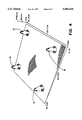
- FIG. 1 is simplified block diagram of a system suitable for practicing this invention
- FIG. 2 is a graph, generated from data obtained with a surface profilometer, that illustrates a lens profile with a 130 ⁇ m focal length;
- FIG. 3 is an enlarged elevational view of a single refractive microlens having a diameter of approximately 9 ⁇ m;
- FIG. 4 is an enlarged elevational view of a plurality of microlenses that form a portion of a two-dimensional array of microlenses
- FIG. 5 is a graph, generated from data obtained with an atomic force microscope, showing the profiles of a plurality of the microlenses of FIG. 4;
- FIG. 6 is an enlarged planar view of the array of FIG. 4;
- FIGS. 7A and 7B illustrate a far field pattern of a single-mode fiber output taken through the SDG substrate before the fabrication of a microlens shown in FIG. 3;
- FIGS. 8A and 8B illustrate a far field pattern of the single-mode fiber output taken through the SDG substrate after propagation through the microlens shown in FIG. 3;
- FIG. 9 is an enlarged cross-sectional view, not scale, of a plurality of microlenses fabricated in accordance with this invention.
- a microlens is intended to encompass an optical structure that is suitable for redirecting (e.g., focussing, concentrating, diverging, or collimating) electromagnetic radiation, that is formed upon a surface of a substrate, that is integral with and comprised of a material that is substantially the same as a material of the substrate (except as is detailed below), and that has a diameter that is equal to or less than approximately one millimeter (i.e., less than approximately 10 3 micrometers).
- FIG. 1 illustrates a system 10 suitable for practicing a microlens fabrication method of this invention.
- a laser 12 has an output coupled to a suitable beam delivery system 13, such as an articulated arm, mirrors and the like, which is positioned for directing the laser energy (indicated as a focussed beam A) to a surface 16a of a substrate 16.
- the laser light is preferably focussed by one or more optical elements 14.
- the surface 16a is the surface upon which at least one refractive microlens 18 is to be formed, and the substrate 16 is comprised of a wavelength-selective optical absorber.
- the wavelength-selective optical absorber is comprised of semiconductor particles (referred to herein interchangeably as semiconductor nanocrystallites and semiconductor microcrystallites) that are embedded within a transparent (at wavelengths of interest) glass matrix.
- the focussed laser light when generated with a wavelength that is equal to or greater than the bandgap wavelength of the semiconductor microcrystallites within the substrate 16, is absorbed and causes a localized heating and melting of the glass matrix adjacent to the surface 16a.
- the bandgap wavelength of a semiconductor material is intended to mean a wavelength that corresponds to a photon having an energy sufficient to generate electron-hole pairs in the semiconductor material (i.e., an energy sufficient to raise an electron from the valence band to the conduction band).
- the localized melting of the glass matrix results in the formation of a raised ⁇ bump ⁇ of SDG material on the surface 16a.
- the molten material of the substrate 16 exhibits a relatively large density change (e.g., 10-20% ), which then wells up above the surface 16a before solidifying into a generally parabolic lens-like shape that forms, when re-solidified, the microlens 18.
- the raised ⁇ bump ⁇ has been found to function as a refractive lens for light.
- the bump or lens is typically absorbing for light whose energy is above the bandgap of the semiconductor material. For some applications this absorption may be desirable (e.g., a filtering lens).
- the substrate 16 is preferably mounted to a multi-degree of freedom positioning mechanism, such as an X-Y stage 20, so that the surface 16a of the substrate 16 can be located at a desired position relative to the focussed beam A.
- a multi-degree of freedom positioning mechanism such as an X-Y stage 20
- the use of the X-Y stage 20 is particularly advantageous when a plurality of microlenses 18 are to be fabricated as a one-dimensional or a two-dimensional array.
- a Z-axis stage 22 can also be employed for controlling the size of the focussed spot of laser light on the surface 16 and, hence, the diameter and profile of the microlens 18.
- a suitable controller 24 is provided for operating the positioning mechanisms 20 and 22 and, optionally, also the laser 12.
- the substrate 16 is preferably comprised of a volume of silica-based glass host material having a plurality of semiconductor nanocrystallites embedded therein.
- the substrate 16 is comprised of a borosilicate glass host material containing CdS.sub.(1-x) Se X nanocrystallites.
- the nanocrystallites are typically uniformly distributed throughout the glass host material and have a nominal spacing between them that is a function of the concentration (typically in a range of approximately 0.3 mole percent to approximately 50 mole percent or greater) of the nanocrystallites.
- the concentration of the microcrystallites should be adequate to cause enough of a localized heating effect, at a selected laser intensity, to induce the localized melting of the glass host.
- the glass host may include, by example, PbS, CuCl, GaAs, InP, ZnSe, or ZnSeS semiconductor nanocrystallites.
- a semiconductor nanocrystallite or microcrystallite is considered to be a single crystal or a polycrystalline aggregate of a semiconductor material having an energy band structure and an associated bandgap energy.
- the nanocrystallites are randomly oriented and have typical dimensions on the order of approximately 100 Angstroms to approximately 200 Angstroms.
- Commercially available glasses containing such semiconductor nanocrystallites are used as optical filters.
- a series of such filters is available from Schott Glass, the filters being identified with a nomenclature that includes a number, such as 495, which gives the approximate semiconductor bandgap in nanometers.
- the teaching of this invention is, of course, not limited to use with only commercially available SDG substrate materials.
- the light When exposed to light having wavelengths equal to or shorter than a wavelength associated with the bandgap energy, the light is absorbed by the semiconductor nanocrystallites, thereby creating the localized heating of the surrounding glass host or matrix. Light having wavelengths longer than the wavelength associated with the bandgap energy is not appreciably absorbed, and is transmitted through the glass host.
- FIG. 2 illustrates a surface profilometer scan of the surface 16a of the SDG substrate 16 after exposure to the focused beam A of laser light.
- the data shows that the laser 12 has produced a small bump on the surface 16a.
- This bump forms the refractive microlens 18 which transmits light having wavelengths longer than the bandgap wavelength.
- an index of refraction change in the affected SDG material of the microlens 18, as well as for a migration of the semiconductor nanocrystallites away from molten glass that forms the microlens 18 (as is illustrated in FIG. 9). Both of these effects are believed to contribute to the phase shift of light passing through the microlens 18.
- the reduction in the index of refraction within the microlens 18 is proportional to the reduction in the (final) density of the glass host material within the microlens 18, as compared to the density in the bulk of the substrate 16.
- a 1% reduction in the final density of the material of the microlens 18 results in an approximate 1% reduction in the index of refraction.
- Threshold laser powers for microlens formation are on the order of hundreds of mW at room temperature, and decrease nearly linearly to tens of mW at temperatures near 300° C. This decrease in power requirements is due to an observed sharp rise in the SDG absorption with temperature. At or slightly above threshold intensities a microlens may take in excess of ten seconds to form, while at intensities significantly above threshold less than one second is required for microlens formation.
- the diameter of the microlens 18 is a function of the size of the incident laser beam A, the wavelength of the beam, and the total exposure time to the beam. Lens diameters from approximately 8 ⁇ m to 170 ⁇ m have been demonstrated, with no observed impediment to increasing the diameter to greater than 170 ⁇ m (to, by example, at least 500 ⁇ m).
- the profile of the microlenses 18 fabricated in accordance with the method of this invention has been found to be generally well fitted by parabolic as well as spherical functions.
- FIG. 3 is an enlarged elevational view of a single refractive microlens 18 having a diameter of approximately 9 ⁇ m.
- FIG. 4 is an enlarged elevational view of a plurality of microlenses 18 that form a portion of a two-dimensional array.
- FIG. 5 is a graph, generated from data obtained with an atomic force microscope, which shows the profiles of a plurality of the microlenses 18 of FIG. 4.
- FIG. 6 is an enlarged planar view of the array of FIG. 4.
- the points labeled 1-4 correspond to the dimensions shown in Table 1.
- FIGS. 7A and 7B illustrate a far field pattern of a single-mode fiber output taken through the SDG substrate 16 before the fabrication of the microlens 18 shown in FIG. 3.
- FIGS. 8A and 8B illustrate a far field pattern of the single-mode fiber output taken through the SDG substrate 16 after propagation through the microlens 18 shown in FIG. 3.
- FIGS. 8A and 8B illustrate the focusing of the output of the single mode fiber at a distance of 16 mm, with the microlens 18 being located 430 ⁇ m from the tip of the fiber. This degree of focusing was produced with the microlens 18 of FIG. 3 which had a diameter of 130 ⁇ m and a height of 60 ⁇ m.
- the selection of a suitable laser is a function of the bandgap wavelength of the selected SDG substrate 16, which in turn is a function of the desired band of wavelengths which are desired to be transmitted through the microlens 18.
- focused cw laser light at 5145 Angstroms can be used with OG550 SDG to produce microlenses which can be used at all wavelengths longer than 5500 Angstroms.
- a SDG substrate containing CuCl nanocrystallites can be selected (CuCl has a bandgap wavelength in the ultra-violet (UV) range).
- An Argon-ion UV laser or a frequency tripled cw mode locked Nd:YAG laser having an output wavelength in the UV (above the bandgap wavelength of CuCl) can then be employed as the laser 12 in FIG. 1.
- Other suitable laser types include, but are not limited to, frequency doubled Nd:YAG lasers, Argon lasers, and dye lasers.
- a relatively large diameter microlens 18a can be fabricated first, followed by one or more smaller diameter microlenses 18b that are formed on the larger microlens 18a.
- the substrate 16 can be positioned along the z-axis so as to form a first focal spot size on the surface to fabricate the larger microlens 18a, after which the substrate 16 can be translated along the z-axis to reduce the diameter of the focal spot (and optionally also along the x and y axes) to fabricate the smaller microlens 18a.
- a single microlens (or an array of microlenses) can be fabricated to have complex optical profiles and characteristics.
- FIG. 9 also illustrates the depletion of the semiconductor nanocrystallites (indicated as 17) within the microlenses 18, 18a and 18b, as compared to the concentration within the glass host that does not experience the localized melting.
- FIG. 9 also illustrates the focussing to a focal point (FP) of below bandgap wavelength ( ⁇ ) light by the microlens 18. Illumination of the substrate 16 can also be accomplished through the surface opposite the surface 16a upon which the microlens 18 is formed.
- FP focal point
- ⁇ bandgap wavelength
- the thickness of the substrate 16 can be adjusted as desired either before or after microlens fabrication.
- a suitable anti-reflection coating can be applied to a radiation-receiving surface of the substrate 16.
- the completed structure can be integrated as desired with other optical components, such as electromagnetic radiation emitters (e.g., an array of laser diodes) or electromagnetic radiation receivers (e.g., an array of photodetectors) so as to focus or collimate electromagnetic radiation having wavelengths longer than the bandgap wavelength of the semiconductor nanocrystallites that are embedded within the substrate 16.
- electromagnetic radiation emitters e.g., an array of laser diodes
- electromagnetic radiation receivers e.g., an array of photodetectors
- Free space optical interconnects can also be constructed using the microlenses of this invention.
- wavelength-selective materials other than semiconductor microcrystallites
- glasses doped with ions such as Cerium, Neodymium and Europium
- matrix materials other than glass
- the matrix material may be employed without a dopant, and a suitable laser, such as an IR CO 2 laser, is employed for forming the microlenses.
- phase plates phase plates
- phase masks phase masks
- anamorphic optics for diode laser collimation can also be fabricated by the method of this invention, such as phase plates, phase masks, and anamorphic optics for diode laser collimation. It should further be realized that the microlens formation can occur in a vacuum or in an atmosphere selected for influencing the cooling rate and/or other parameters of the molten substrate material.
Abstract
Description
TABLE 1
______________________________________
Distance
Height
______________________________________
#1 9.44 μm
10.17 nm
# 2 4.72 μm
1758.18 nm
# 3 9.10 μm
15.98 nm
# 4 5.06 μm
1634.56 nm
______________________________________
Claims (19)
Priority Applications (5)
| Application Number | Priority Date | Filing Date | Title |
|---|---|---|---|
| US08/400,835 US5604635A (en) | 1995-03-08 | 1995-03-08 | Microlenses and other optical elements fabricated by laser heating of semiconductor doped and other absorbing glasses |
| US08/586,437 US5768022A (en) | 1995-03-08 | 1996-01-16 | Laser diode having in-situ fabricated lens element |
| EP96906550A EP0826162A4 (en) | 1995-03-08 | 1996-02-28 | Fabrication of microlenses and devices that include microlenses |
| PCT/US1996/002268 WO1996027815A1 (en) | 1995-03-08 | 1996-02-28 | Fabrication of microlenses and devices that include microlenses |
| US08/796,083 US5737126A (en) | 1995-03-08 | 1997-02-05 | Microlenses and other optical elements fabricated by laser heating of semiconductor doped and other absorbing glasses |
Applications Claiming Priority (1)
| Application Number | Priority Date | Filing Date | Title |
|---|---|---|---|
| US08/400,835 US5604635A (en) | 1995-03-08 | 1995-03-08 | Microlenses and other optical elements fabricated by laser heating of semiconductor doped and other absorbing glasses |
Related Child Applications (2)
| Application Number | Title | Priority Date | Filing Date |
|---|---|---|---|
| US08/586,437 Continuation-In-Part US5768022A (en) | 1995-03-08 | 1996-01-16 | Laser diode having in-situ fabricated lens element |
| US08/796,083 Division US5737126A (en) | 1995-03-08 | 1997-02-05 | Microlenses and other optical elements fabricated by laser heating of semiconductor doped and other absorbing glasses |
Publications (1)
| Publication Number | Publication Date |
|---|---|
| US5604635A true US5604635A (en) | 1997-02-18 |
Family
ID=23585223
Family Applications (2)
| Application Number | Title | Priority Date | Filing Date |
|---|---|---|---|
| US08/400,835 Expired - Fee Related US5604635A (en) | 1995-03-08 | 1995-03-08 | Microlenses and other optical elements fabricated by laser heating of semiconductor doped and other absorbing glasses |
| US08/796,083 Expired - Lifetime US5737126A (en) | 1995-03-08 | 1997-02-05 | Microlenses and other optical elements fabricated by laser heating of semiconductor doped and other absorbing glasses |
Family Applications After (1)
| Application Number | Title | Priority Date | Filing Date |
|---|---|---|---|
| US08/796,083 Expired - Lifetime US5737126A (en) | 1995-03-08 | 1997-02-05 | Microlenses and other optical elements fabricated by laser heating of semiconductor doped and other absorbing glasses |
Country Status (1)
| Country | Link |
|---|---|
| US (2) | US5604635A (en) |
Cited By (33)
| Publication number | Priority date | Publication date | Assignee | Title |
|---|---|---|---|---|
| US5801884A (en) * | 1995-10-09 | 1998-09-01 | Mitsubishi Chemical Corporation | Optical device and process for producing the same |
| WO1999050052A1 (en) * | 1998-03-31 | 1999-10-07 | Intel Corporation | Microlens formation through focal plane control of an aerial image |
| US6038060A (en) * | 1997-01-16 | 2000-03-14 | Crowley; Robert Joseph | Optical antenna array for harmonic generation, mixing and signal amplification |
| US6122109A (en) * | 1998-04-16 | 2000-09-19 | The University Of New Mexico | Non-planar micro-optical structures |
| EP1045449A2 (en) * | 1999-04-12 | 2000-10-18 | Matsushita Electric Industrial Co., Ltd. | Solid-state imaging device |
| US6593067B2 (en) * | 2001-07-10 | 2003-07-15 | Postech Foundation | Method for manufacturing a microstructure by using a high energy light source |
| US20030143337A1 (en) * | 2001-11-16 | 2003-07-31 | Semiconductor Energy Laboratory Co., Ltd. | Method of irradiating a laser beam, apparatus for irradiating a laser beam and method of fabricating semiconductor devices |
| US20030209040A1 (en) * | 2002-04-18 | 2003-11-13 | Takahiro Hashimoto | Method for producing planar lens and planar lens array |
| US6700550B2 (en) | 1997-01-16 | 2004-03-02 | Ambit Corporation | Optical antenna array for harmonic generation, mixing and signal amplification |
| US6864972B1 (en) * | 2001-07-26 | 2005-03-08 | Advanced Micro Devices, Inc. | IC die analysis via back side lens |
| US20050200961A1 (en) * | 2002-06-17 | 2005-09-15 | Michael Rosenbluh | Microlens and method of marking same |
| US20070047056A1 (en) * | 2005-08-24 | 2007-03-01 | The Trustees Of Boston College | Apparatus and methods for solar energy conversion using nanocoax structures |
| US20070081242A1 (en) * | 2005-08-24 | 2007-04-12 | The Trustees Of Boston College | Apparatus and methods for optical switching using nanoscale optics |
| US20070099401A1 (en) * | 2001-08-03 | 2007-05-03 | Semiconductor Energy Laboratory Co., Ltd. | Laser irradiating device, laser irradiating method and manufacturing method of semiconductor device |
| US20070105240A1 (en) * | 2005-08-24 | 2007-05-10 | The Trustees Of Boston College | Apparatus and methods for nanolithography using nanoscale optics |
| US20070107103A1 (en) * | 2005-08-24 | 2007-05-10 | The Trustees Of Boston College | Apparatus and methods for manipulating light using nanoscale cometal structures |
| US20070137697A1 (en) * | 2005-08-24 | 2007-06-21 | The Trustees Of Boston College | Apparatus and methods for solar energy conversion using nanoscale cometal structures |
| US20070240757A1 (en) * | 2004-10-15 | 2007-10-18 | The Trustees Of Boston College | Solar cells using arrays of optical rectennas |
| US20080178924A1 (en) * | 2007-01-30 | 2008-07-31 | Solasta, Inc. | Photovoltaic cell and method of making thereof |
| US20080202581A1 (en) * | 2007-02-12 | 2008-08-28 | Solasta, Inc. | Photovoltaic cell with reduced hot-carrier cooling |
| US20080213542A1 (en) * | 2006-07-07 | 2008-09-04 | Qun Huo | Laser processing of metal nanoparticle/polymer composites |
| US20080250665A1 (en) * | 2007-01-25 | 2008-10-16 | Mitutoyo Corporation | Digital displacement measuring instrument |
| US20090007956A1 (en) * | 2007-07-03 | 2009-01-08 | Solasta, Inc. | Distributed coax photovoltaic device |
| US7505650B1 (en) | 2008-03-28 | 2009-03-17 | Corning Incorporated | Microlenses for optical assemblies and related methods |
| US7531104B1 (en) | 2002-03-20 | 2009-05-12 | Ruey-Jen Hwu | Micro-optic elements and method for making the same |
| US20090175050A1 (en) * | 2006-05-18 | 2009-07-09 | Marttila Charles A | Process for making light guides with extraction structures and light guides produced thereby |
| US7583444B1 (en) * | 2005-12-21 | 2009-09-01 | 3M Innovative Properties Company | Process for making microlens arrays and masterforms |
| US20090295188A1 (en) * | 2008-05-29 | 2009-12-03 | Plasan Sasa Ltd. | Interchangeable door |
| US7630609B1 (en) | 2005-07-07 | 2009-12-08 | Megladon Manufacturing Group, Ltd. | Arrayed multi-fiber connector |
| DE102008056136A1 (en) * | 2008-10-29 | 2010-05-20 | 3D-Micromac Ag | Laser marking method, laser marking device and optical element |
| US20100183846A1 (en) * | 2007-07-16 | 2010-07-22 | Grzybowski Richard R | Method for local reversible glass swelling |
| US20130321903A1 (en) * | 2012-05-29 | 2013-12-05 | Richard Robert Grzybowski | Sheet glass product fabrication with growth-limited glass bump spacers |
| US20140123703A1 (en) * | 2012-11-06 | 2014-05-08 | Philip Robert LeBlanc | Thickness control of substrates |
Families Citing this family (24)
| Publication number | Priority date | Publication date | Assignee | Title |
|---|---|---|---|---|
| JP5067684B2 (en) * | 2001-06-14 | 2012-11-07 | Nltテクノロジー株式会社 | Liquid crystal display device and manufacturing method thereof |
| US20040016718A1 (en) * | 2002-03-20 | 2004-01-29 | Ruey-Jen Hwu | Micro-optic elements and method for making the same |
| RU2602397C2 (en) * | 2003-11-21 | 2016-11-20 | Визуал Физикс, Ллс | Micro-optical safety and image display system |
| US8867134B2 (en) * | 2003-11-21 | 2014-10-21 | Visual Physics, Llc | Optical system demonstrating improved resistance to optically degrading external effects |
| US8550985B2 (en) * | 2004-12-14 | 2013-10-08 | Boston Scientific Scimed, Inc. | Applications of LIPSS in polymer medical devices |
| US8202245B2 (en) * | 2005-01-26 | 2012-06-19 | Boston Scientific Scimed, Inc. | Medical devices and methods of making the same |
| BRPI0610706B8 (en) * | 2005-05-18 | 2021-06-22 | Nanoventions Holdings Llc | synthetic optical imaging system, document security device, image presentation system and security device or authentication system |
| ES2299335B2 (en) * | 2006-03-09 | 2010-10-13 | Universidad De Cadiz | METHOD FOR THE MANUFACTURE OF OPTICAL STRUCTURES WITH PURELY REFRACTIVE FUNCTIONALITY. |
| KR20090028523A (en) * | 2006-05-12 | 2009-03-18 | 크레인 앤드 캄파니 인코퍼레이티드 | A micro-optic film structure that alone or together with a security document or label projects images spatially coordinated with static images and/or other projected images |
| DE102008018042B4 (en) * | 2008-04-09 | 2011-04-21 | Zwiesel Kristallglas Aktiengesellschaft | Method for producing raised and / or drawn structures on hollow bodies, preferably of glass |
| EP2108625B1 (en) * | 2008-04-09 | 2013-03-27 | Zwiesel Kristallglas AG | Method for generating embossed/retracted structures on hollow ware, preferably made of glass |
| CN102497994B (en) * | 2009-08-12 | 2015-11-25 | 光学物理有限责任公司 | tamper indicating optical security device |
| KR102012526B1 (en) | 2011-01-28 | 2019-08-20 | 크레인 앤 코, 인크 | A laser marked device |
| JP2014524600A (en) | 2011-08-19 | 2014-09-22 | ビジュアル フィジクス エルエルシー | Optical system capable of transfer on demand with reduced thickness |
| ES2959465T3 (en) | 2012-08-17 | 2024-02-26 | Visual Physics Llc | A procedure for transferring microstructures to a final substrate |
| AU2014228012B2 (en) | 2013-03-15 | 2018-07-26 | Visual Physics, Llc | Optical security device |
| US9429769B2 (en) * | 2013-05-09 | 2016-08-30 | Johnson & Johnson Vision Care, Inc. | Ophthalmic device with thin film nanocrystal integrated circuits |
| US9873281B2 (en) | 2013-06-13 | 2018-01-23 | Visual Physics, Llc | Single layer image projection film |
| US10766292B2 (en) | 2014-03-27 | 2020-09-08 | Crane & Co., Inc. | Optical device that provides flicker-like optical effects |
| BR112016021736A2 (en) | 2014-03-27 | 2017-08-15 | Visual Physics Llc | OPTICAL DEVICE PRODUCING SPARKLING-TYPE OPTICAL EFFECTS |
| EP3287295A1 (en) | 2014-07-17 | 2018-02-28 | Visual Physics, LLC | An improved polymeric sheet material for use in making polymeric security documents such as bank notes |
| US10195890B2 (en) | 2014-09-16 | 2019-02-05 | Crane Security Technologies, Inc. | Secure lens layer |
| JP6947358B2 (en) | 2015-02-11 | 2021-10-13 | クレイン アンド カンパニー、 インコーポレイテッド | How to attach the surface of the security device to the board |
| US11590791B2 (en) | 2017-02-10 | 2023-02-28 | Crane & Co., Inc. | Machine-readable optical security device |
Citations (19)
| Publication number | Priority date | Publication date | Assignee | Title |
|---|---|---|---|---|
| US3586816A (en) * | 1968-07-25 | 1971-06-22 | American Optical Corp | Spot welding system and method |
| US3689264A (en) * | 1970-03-19 | 1972-09-05 | Bell Telephone Labor Inc | Method for increasing index of refraction in transparent bodies and its application to light guides and the like |
| US3948660A (en) * | 1972-08-05 | 1976-04-06 | Agfa-Gevaert, A.G. | Method for the manufacture of fresnel lenses using light-sensitive materials |
| US4439245A (en) * | 1982-01-25 | 1984-03-27 | Rca Corporation | Electromagnetic radiation annealing of semiconductor material |
| US4478768A (en) * | 1982-03-15 | 1984-10-23 | Tokyo Shibaura Denki Kabushiki Kaisha | Method for manufacturing optical type recording medium |
| SU1252306A1 (en) * | 1985-03-11 | 1986-08-23 | Ленинградский Ордена Октябрьской Революции И Ордена Трудового Красного Знамени Технологический Институт Им.Ленсовета | Method of manufacturing optical components |
| US4729641A (en) * | 1983-06-10 | 1988-03-08 | Canon Kabushiki Kaisha | Functional optical element having a non-flat planar interface with variable-index medium |
| US4734729A (en) * | 1985-08-06 | 1988-03-29 | Eastman Kodak Company | Studded squeegee roller |
| US4775967A (en) * | 1984-10-11 | 1988-10-04 | Hitachi, Ltd. | Beam spot control device using a thin micro lens with an actuator |
| US4842782A (en) * | 1986-10-14 | 1989-06-27 | Allergan, Inc. | Manufacture of ophthalmic lenses by excimer laser |
| US4899048A (en) * | 1987-04-27 | 1990-02-06 | Printware, Inc. | Focused optical beam encoder of position |
| GB2233334A (en) * | 1989-06-29 | 1991-01-09 | Exitech Ltd | Surface treatment of polymer materials by the action of pulses of UV radiation |
| US5053171A (en) * | 1986-10-14 | 1991-10-01 | Allergan, Inc. | Manufacture of ophthalmic lenses by excimer laser |
| US5148322A (en) * | 1989-11-09 | 1992-09-15 | Omron Tateisi Electronics Co. | Micro aspherical lens and fabricating method therefor and optical device |
| US5208698A (en) * | 1990-12-19 | 1993-05-04 | The Mitre Corporation | Optically-neutral laser shield |
| US5260826A (en) * | 1992-01-21 | 1993-11-09 | Physical Optics Corporation | Nonscanning sectioning microscope |
| US5294518A (en) * | 1992-05-01 | 1994-03-15 | International Business Machines Corporation | Amorphous write-read optical storage memory |
| US5491762A (en) * | 1994-09-09 | 1996-02-13 | Deacon Research | ATM switch with electrically-controlled waveguide-routing |
| US5500869A (en) * | 1993-03-23 | 1996-03-19 | Mitsubishi Denki Kabushiki Kaisha | Semiconductor laser array device, semiconductor laser device, and production methods therefor |
Family Cites Families (11)
| Publication number | Priority date | Publication date | Assignee | Title |
|---|---|---|---|---|
| SU451155A1 (en) * | 1972-11-13 | 1974-11-25 | Предприятие П/Я А-3904 | Device for protecting discharge tube windows |
| FR2398318A1 (en) * | 1977-07-21 | 1979-02-16 | Quantel Sa | OPTICAL FILTER ELEMENT AND SPECTRAL REFINING DEVICE WITH APPLICATION |
| US4229710A (en) * | 1977-10-21 | 1980-10-21 | Itamar Shoshan | Wavelength selector for tunable laser |
| NL178465C (en) * | 1980-09-05 | 1986-03-17 | Stichting Res & Tech | LASER DEVICE. |
| US4561086A (en) * | 1983-05-12 | 1985-12-24 | Eastman Kodak Company | Optical write/read unit with selective-transparency cover |
| DE3326092A1 (en) * | 1983-07-20 | 1985-01-31 | Honeywell Gmbh, 6050 Offenbach | LASER |
| JPS6060791A (en) * | 1983-09-13 | 1985-04-08 | Hitachi Ltd | Window for laser beam |
| JPS6120368A (en) * | 1984-07-09 | 1986-01-29 | Toshiba Corp | Planar semiconductor device |
| US5070509A (en) * | 1990-08-09 | 1991-12-03 | Eastman Kodak Company | Surface emitting, low threshold (SELTH) laser diode |
| GB9020096D0 (en) * | 1990-09-14 | 1990-10-24 | De Beers Ind Diamond | Window |
| CA2110681A1 (en) * | 1991-06-05 | 1992-12-10 | Peter Samuel Atherton | Optical memories incorporating diffraction gratings |
-
1995
- 1995-03-08 US US08/400,835 patent/US5604635A/en not_active Expired - Fee Related
-
1997
- 1997-02-05 US US08/796,083 patent/US5737126A/en not_active Expired - Lifetime
Patent Citations (19)
| Publication number | Priority date | Publication date | Assignee | Title |
|---|---|---|---|---|
| US3586816A (en) * | 1968-07-25 | 1971-06-22 | American Optical Corp | Spot welding system and method |
| US3689264A (en) * | 1970-03-19 | 1972-09-05 | Bell Telephone Labor Inc | Method for increasing index of refraction in transparent bodies and its application to light guides and the like |
| US3948660A (en) * | 1972-08-05 | 1976-04-06 | Agfa-Gevaert, A.G. | Method for the manufacture of fresnel lenses using light-sensitive materials |
| US4439245A (en) * | 1982-01-25 | 1984-03-27 | Rca Corporation | Electromagnetic radiation annealing of semiconductor material |
| US4478768A (en) * | 1982-03-15 | 1984-10-23 | Tokyo Shibaura Denki Kabushiki Kaisha | Method for manufacturing optical type recording medium |
| US4729641A (en) * | 1983-06-10 | 1988-03-08 | Canon Kabushiki Kaisha | Functional optical element having a non-flat planar interface with variable-index medium |
| US4775967A (en) * | 1984-10-11 | 1988-10-04 | Hitachi, Ltd. | Beam spot control device using a thin micro lens with an actuator |
| SU1252306A1 (en) * | 1985-03-11 | 1986-08-23 | Ленинградский Ордена Октябрьской Революции И Ордена Трудового Красного Знамени Технологический Институт Им.Ленсовета | Method of manufacturing optical components |
| US4734729A (en) * | 1985-08-06 | 1988-03-29 | Eastman Kodak Company | Studded squeegee roller |
| US4842782A (en) * | 1986-10-14 | 1989-06-27 | Allergan, Inc. | Manufacture of ophthalmic lenses by excimer laser |
| US5053171A (en) * | 1986-10-14 | 1991-10-01 | Allergan, Inc. | Manufacture of ophthalmic lenses by excimer laser |
| US4899048A (en) * | 1987-04-27 | 1990-02-06 | Printware, Inc. | Focused optical beam encoder of position |
| GB2233334A (en) * | 1989-06-29 | 1991-01-09 | Exitech Ltd | Surface treatment of polymer materials by the action of pulses of UV radiation |
| US5148322A (en) * | 1989-11-09 | 1992-09-15 | Omron Tateisi Electronics Co. | Micro aspherical lens and fabricating method therefor and optical device |
| US5208698A (en) * | 1990-12-19 | 1993-05-04 | The Mitre Corporation | Optically-neutral laser shield |
| US5260826A (en) * | 1992-01-21 | 1993-11-09 | Physical Optics Corporation | Nonscanning sectioning microscope |
| US5294518A (en) * | 1992-05-01 | 1994-03-15 | International Business Machines Corporation | Amorphous write-read optical storage memory |
| US5500869A (en) * | 1993-03-23 | 1996-03-19 | Mitsubishi Denki Kabushiki Kaisha | Semiconductor laser array device, semiconductor laser device, and production methods therefor |
| US5491762A (en) * | 1994-09-09 | 1996-02-13 | Deacon Research | ATM switch with electrically-controlled waveguide-routing |
Non-Patent Citations (12)
| Title |
|---|
| "Binary Optics", W. Veldkamp and Thomas J. McHugh, Scientific American, May 1992, pp. 92-97. |
| "The topography of laser-irrudiated germanium", D. C. Emmony et al., Journal of Physics D; Applied Physics, vol. 8, 1975, pp. 1472-1480. |
| B. F. Aull et al., "Application Of Smart-Pixel and Microlens Arrays To Early Vision", Leos '94 Conference Proceedings, vol. 1, 1994, pp. 149-150. |
| B. F. Aull et al., Application Of Smart Pixel and Microlens Arrays To Early Vision , Leos 94 Conference Proceedings, vol. 1, 1994, pp. 149 150. * |
| Binary Optics , W. Veldkamp and Thomas J. McHugh, Scientific American, May 1992, pp. 92 97. * |
| S. S. Lee et al., "An 8x1 Micromachined Micro-Fresnel Lens Array For Free-Space Optical Interconnect", Leos '94 Conference Proceedings, vol. 1, 1994, pp. 242-243. |
| S. S. Lee et al., An 8x1 Micromachined Micro Fresnel Lens Array For Free Space Optical Interconnect , Leos 94 Conference Proceedings, vol. 1, 1994, pp. 242 243. * |
| The topography of laser irrudiated germanium , D. C. Emmony et al., Journal of Physics D; Applied Physics, vol. 8, 1975, pp. 1472 1480. * |
| W. R. Cox et al., "Microjet Fabrication of Micro-Optical Components", Leos '94 Conference Proceedings, vol. 1, 1994, pp. 52-53. |
| W. R. Cox et al., Microjet Fabrication of Micro Optical Components , Leos 94 Conference Proceedings, vol. 1, 1994, pp. 52 53. * |
| Z. L. Liau et al., "Mass-Transport Efficient Microlenses In GaAs And GaP For Integration With High Power Diode Lasers", Leos '94 Conference Proceedings, vol. 1, 1994, pp. 67-68. |
| Z. L. Liau et al., Mass Transport Efficient Microlenses In GaAs And GaP For Integration With High Power Diode Lasers , Leos 94 Conference Proceedings, vol. 1, 1994, pp. 67 68. * |
Cited By (68)
| Publication number | Priority date | Publication date | Assignee | Title |
|---|---|---|---|---|
| US5801884A (en) * | 1995-10-09 | 1998-09-01 | Mitsubishi Chemical Corporation | Optical device and process for producing the same |
| US6038060A (en) * | 1997-01-16 | 2000-03-14 | Crowley; Robert Joseph | Optical antenna array for harmonic generation, mixing and signal amplification |
| US6700550B2 (en) | 1997-01-16 | 2004-03-02 | Ambit Corporation | Optical antenna array for harmonic generation, mixing and signal amplification |
| WO1999050052A1 (en) * | 1998-03-31 | 1999-10-07 | Intel Corporation | Microlens formation through focal plane control of an aerial image |
| US6507439B1 (en) | 1998-03-31 | 2003-01-14 | Intel Corporation | Microlens formation through focal plane control of an aerial image |
| US6122109A (en) * | 1998-04-16 | 2000-09-19 | The University Of New Mexico | Non-planar micro-optical structures |
| US6728289B1 (en) | 1998-04-16 | 2004-04-27 | Science & Technology Corporation @ University Of New Mexico | Non-planar micro-optical structures |
| US6365237B1 (en) | 1998-04-16 | 2002-04-02 | University Of New Mexico | Method of making non-planar micro-optical structures |
| EP1045449A3 (en) * | 1999-04-12 | 2002-06-12 | Matsushita Electric Industrial Co., Ltd. | Solid-state imaging device |
| US6583438B1 (en) | 1999-04-12 | 2003-06-24 | Matsushita Electric Industrial Co., Ltd. | Solid-state imaging device |
| US20030197210A1 (en) * | 1999-04-12 | 2003-10-23 | Shinji Uchida | Solid-state imaging device |
| US6831311B2 (en) | 1999-04-12 | 2004-12-14 | Matsushita Electric Industrial Co., Ltd. | Solid-state imaging device |
| EP1045449A2 (en) * | 1999-04-12 | 2000-10-18 | Matsushita Electric Industrial Co., Ltd. | Solid-state imaging device |
| US6593067B2 (en) * | 2001-07-10 | 2003-07-15 | Postech Foundation | Method for manufacturing a microstructure by using a high energy light source |
| US6864972B1 (en) * | 2001-07-26 | 2005-03-08 | Advanced Micro Devices, Inc. | IC die analysis via back side lens |
| US8003499B2 (en) | 2001-08-03 | 2011-08-23 | Semiconductor Energy Laboratory Co., Ltd. | Laser irradiating device, laser irradiating method and manufacturing method of semiconductor device |
| US8767782B2 (en) | 2001-08-03 | 2014-07-01 | Semiconductor Energy Laboratory Co., Ltd. | Laser irradiating device, laser irradiating method and manufacturing method of semiconductor device |
| US7868267B2 (en) | 2001-08-03 | 2011-01-11 | Semiconductor Energy Laboratory Co., Ltd. | Laser irradiating device, laser irradiating method and manufacturing method of semiconductor device |
| US20070099401A1 (en) * | 2001-08-03 | 2007-05-03 | Semiconductor Energy Laboratory Co., Ltd. | Laser irradiating device, laser irradiating method and manufacturing method of semiconductor device |
| US7351647B2 (en) | 2001-11-16 | 2008-04-01 | Semiconductor Energy Laboratory Co., Ltd. | Method of irradiating a laser beam, apparatus for irradiating a laser beam and method of fabricating semiconductor devices |
| US7026227B2 (en) * | 2001-11-16 | 2006-04-11 | Semiconductor Energy Laboratory Co., Ltd. | Method of irradiating a laser beam, and method of fabricating semiconductor devices |
| US20060166470A1 (en) * | 2001-11-16 | 2006-07-27 | Semiconductor Energy Laboratory Co., Ltd. | Method of irradiating a laser beam, apparatus for irradiating a laser beam and method of fabricating semiconductor devices |
| US20030143337A1 (en) * | 2001-11-16 | 2003-07-31 | Semiconductor Energy Laboratory Co., Ltd. | Method of irradiating a laser beam, apparatus for irradiating a laser beam and method of fabricating semiconductor devices |
| US7531104B1 (en) | 2002-03-20 | 2009-05-12 | Ruey-Jen Hwu | Micro-optic elements and method for making the same |
| US7152434B2 (en) * | 2002-04-18 | 2006-12-26 | Nippon Sheet Glass Co., Ltd. | Method for producing planar lens and planar lens array |
| US20030209040A1 (en) * | 2002-04-18 | 2003-11-13 | Takahiro Hashimoto | Method for producing planar lens and planar lens array |
| US20050200961A1 (en) * | 2002-06-17 | 2005-09-15 | Michael Rosenbluh | Microlens and method of marking same |
| US20070240757A1 (en) * | 2004-10-15 | 2007-10-18 | The Trustees Of Boston College | Solar cells using arrays of optical rectennas |
| US7630609B1 (en) | 2005-07-07 | 2009-12-08 | Megladon Manufacturing Group, Ltd. | Arrayed multi-fiber connector |
| US20070107103A1 (en) * | 2005-08-24 | 2007-05-10 | The Trustees Of Boston College | Apparatus and methods for manipulating light using nanoscale cometal structures |
| US20070105240A1 (en) * | 2005-08-24 | 2007-05-10 | The Trustees Of Boston College | Apparatus and methods for nanolithography using nanoscale optics |
| US8431816B2 (en) | 2005-08-24 | 2013-04-30 | The Trustees Of Boston College | Apparatus and methods for solar energy conversion using nanoscale cometal structures |
| US20070047056A1 (en) * | 2005-08-24 | 2007-03-01 | The Trustees Of Boston College | Apparatus and methods for solar energy conversion using nanocoax structures |
| US7634162B2 (en) | 2005-08-24 | 2009-12-15 | The Trustees Of Boston College | Apparatus and methods for nanolithography using nanoscale optics |
| US7943847B2 (en) | 2005-08-24 | 2011-05-17 | The Trustees Of Boston College | Apparatus and methods for solar energy conversion using nanoscale cometal structures |
| US20070138376A1 (en) * | 2005-08-24 | 2007-06-21 | The Trustees Of Boston College | Nanoscale optical microscope |
| US20070137697A1 (en) * | 2005-08-24 | 2007-06-21 | The Trustees Of Boston College | Apparatus and methods for solar energy conversion using nanoscale cometal structures |
| US20070081242A1 (en) * | 2005-08-24 | 2007-04-12 | The Trustees Of Boston College | Apparatus and methods for optical switching using nanoscale optics |
| US7649665B2 (en) | 2005-08-24 | 2010-01-19 | The Trustees Of Boston College | Apparatus and methods for optical switching using nanoscale optics |
| US7589880B2 (en) | 2005-08-24 | 2009-09-15 | The Trustees Of Boston College | Apparatus and methods for manipulating light using nanoscale cometal structures |
| US7754964B2 (en) | 2005-08-24 | 2010-07-13 | The Trustees Of Boston College | Apparatus and methods for solar energy conversion using nanocoax structures |
| US7623746B2 (en) | 2005-08-24 | 2009-11-24 | The Trustees Of Boston College | Nanoscale optical microscope |
| US20090284840A1 (en) * | 2005-12-21 | 2009-11-19 | 3M Innovative Properties Company | Process for making microlens arrays and masterforms |
| US7583444B1 (en) * | 2005-12-21 | 2009-09-01 | 3M Innovative Properties Company | Process for making microlens arrays and masterforms |
| US8004767B2 (en) | 2005-12-21 | 2011-08-23 | 3M Innovative Properties Company | Process for making microlens arrays and masterforms |
| US7936956B2 (en) | 2006-05-18 | 2011-05-03 | 3M Innovative Properties Company | Process for making light guides with extraction structures and light guides produced thereby |
| US20090175050A1 (en) * | 2006-05-18 | 2009-07-09 | Marttila Charles A | Process for making light guides with extraction structures and light guides produced thereby |
| US9329326B2 (en) | 2006-05-18 | 2016-05-03 | 3M Innovative Properties Company | Process for making light guides with extraction structures and light guides produced thereby |
| US7941013B2 (en) | 2006-05-18 | 2011-05-10 | 3M Innovative Properties Company | Process for making light guides with extraction structures and light guides produced thereby |
| US20090279321A1 (en) * | 2006-05-18 | 2009-11-12 | 3M Innovative Properties Company | Process for making light guides with extraction structures and light guides produced thereby |
| US20080213542A1 (en) * | 2006-07-07 | 2008-09-04 | Qun Huo | Laser processing of metal nanoparticle/polymer composites |
| US8226878B2 (en) * | 2006-07-07 | 2012-07-24 | University Of Central Florida Research Foundation, Inc. | Laser processing of metal nanoparticle/polymer composites |
| US20080250665A1 (en) * | 2007-01-25 | 2008-10-16 | Mitutoyo Corporation | Digital displacement measuring instrument |
| US20080178924A1 (en) * | 2007-01-30 | 2008-07-31 | Solasta, Inc. | Photovoltaic cell and method of making thereof |
| US20080202581A1 (en) * | 2007-02-12 | 2008-08-28 | Solasta, Inc. | Photovoltaic cell with reduced hot-carrier cooling |
| US20090007956A1 (en) * | 2007-07-03 | 2009-01-08 | Solasta, Inc. | Distributed coax photovoltaic device |
| US20100183846A1 (en) * | 2007-07-16 | 2010-07-22 | Grzybowski Richard R | Method for local reversible glass swelling |
| US8397537B2 (en) * | 2007-07-16 | 2013-03-19 | Corning Incorporated | Method for local reversible glass swelling |
| US7505650B1 (en) | 2008-03-28 | 2009-03-17 | Corning Incorporated | Microlenses for optical assemblies and related methods |
| US20090295188A1 (en) * | 2008-05-29 | 2009-12-03 | Plasan Sasa Ltd. | Interchangeable door |
| US8115792B2 (en) | 2008-10-29 | 2012-02-14 | 3D-Micromac Ag | Laser marking method, laser marking apparatus and optical element |
| US20100141729A1 (en) * | 2008-10-29 | 2010-06-10 | 3D-Micromac Ag | Laser Marking Method, Laser Marking Apparatus and Optical Element |
| DE102008056136A1 (en) * | 2008-10-29 | 2010-05-20 | 3D-Micromac Ag | Laser marking method, laser marking device and optical element |
| US20130321903A1 (en) * | 2012-05-29 | 2013-12-05 | Richard Robert Grzybowski | Sheet glass product fabrication with growth-limited glass bump spacers |
| US9346710B2 (en) * | 2012-05-29 | 2016-05-24 | Corning Incorporated | Sheet glass product fabrication with growth-limited glass bump spacers |
| US10358386B2 (en) | 2012-05-29 | 2019-07-23 | Corning Incorporated | Sheet glass product fabrication with growth-limited glass bump spacers |
| US20140123703A1 (en) * | 2012-11-06 | 2014-05-08 | Philip Robert LeBlanc | Thickness control of substrates |
| US8904822B2 (en) * | 2012-11-06 | 2014-12-09 | Corning Incorporated | Thickness control of substrates |
Also Published As
| Publication number | Publication date |
|---|---|
| US5737126A (en) | 1998-04-07 |
Similar Documents
| Publication | Publication Date | Title |
|---|---|---|
| US5604635A (en) | Microlenses and other optical elements fabricated by laser heating of semiconductor doped and other absorbing glasses | |
| US7505650B1 (en) | Microlenses for optical assemblies and related methods | |
| JP3589486B2 (en) | Microlens manufacturing method | |
| KR20060038382A (en) | Micro-lens array with precisely aligned aperture mask and methods of producing same | |
| EP2294020B1 (en) | Methods of forming raised features on transparent substrates | |
| US20070091977A1 (en) | Method and system for forming periodic pulse patterns | |
| US5768022A (en) | Laser diode having in-situ fabricated lens element | |
| CN100392514C (en) | Parallel Fs laser double photon photopolymerization micro-nano processing method and apparatus thereof | |
| CN101678507A (en) | The pyrometer that is used for laser annealing system of compatible with amorphous carbon optical absorbing layer | |
| US9606419B2 (en) | Adaptive photothermal lens | |
| US20050167410A1 (en) | Methods for creating optical structures in dielectrics using controlled energy deposition | |
| US7152434B2 (en) | Method for producing planar lens and planar lens array | |
| US20030071269A1 (en) | Apparatus and method for laser selective bonding technique for making sealed or enclosed microchannel structures | |
| CN105051859B (en) | By the hot-working for the mid-infrared laser for being transmitted through substrate | |
| WO2020138357A1 (en) | Production method for light-transmittable component and production system for light-transmittable component | |
| NL1035031C2 (en) | OPTICAL PROCESSING AT SELECTIVE DEPTH. | |
| US20090081085A1 (en) | Apparatus for producing three-dimensional structure | |
| Huang et al. | High-efficiency flat-top beam shaper fabricated by a nonlithographic technique | |
| US5670280A (en) | Optically controlled imaging phase mask element | |
| JP3951020B2 (en) | Glass material processing method and glass material processed by the method | |
| US20030174406A1 (en) | Lens array and method for fabricating the lens array | |
| Fu et al. | Large-area Flat Optics via Immersion Lithography on CMOS Platform for Laser Beam Shaping | |
| Srisanit et al. | Low-loss channel waveguide on high-energy-beam sensitive glass | |
| JPH11109117A (en) | Manufacture of diffraction optical element and manufacturing device therefor | |
| JPH02194580A (en) | Manufacture of light-emitting device |
Legal Events
| Date | Code | Title | Description |
|---|---|---|---|
| AS | Assignment |
Owner name: BROWN UNIVERSITY RESEARCH FOUNDATION, RHODE ISLAND Free format text: ASSIGNMENT OF ASSIGNORS INTEREST;ASSIGNOR:LAWANDY, NABIL M.;REEL/FRAME:007387/0691 Effective date: 19950307 |
|
| AS | Assignment |
Owner name: AIR FORCE, UNITED STATES, VIRGINIA Free format text: CONFIRMATORY LICENSE;ASSIGNOR:BROWN UNIVERSITY RESEARCH FOUNDATION;REEL/FRAME:008843/0303 Effective date: 19960715 |
|
| FEPP | Fee payment procedure |
Free format text: PAYOR NUMBER ASSIGNED (ORIGINAL EVENT CODE: ASPN); ENTITY STATUS OF PATENT OWNER: SMALL ENTITY |
|
| REMI | Maintenance fee reminder mailed | ||
| FPAY | Fee payment |
Year of fee payment: 4 |
|
| SULP | Surcharge for late payment | ||
| AS | Assignment |
Owner name: UNITED STATES AIR FORCE, OHIO Free format text: CONFIRMATORY LICENSE;ASSIGNOR:BROWN UNIVERSITY;REEL/FRAME:011206/0437 Effective date: 19960715 |
|
| FEPP | Fee payment procedure |
Free format text: PETITION RELATED TO MAINTENANCE FEES FILED (ORIGINAL EVENT CODE: PMFP); ENTITY STATUS OF PATENT OWNER: SMALL ENTITY |
|
| FEPP | Fee payment procedure |
Free format text: PETITION RELATED TO MAINTENANCE FEES GRANTED (ORIGINAL EVENT CODE: PMFG); ENTITY STATUS OF PATENT OWNER: SMALL ENTITY |
|
| SULP | Surcharge for late payment | ||
| PRDP | Patent reinstated due to the acceptance of a late maintenance fee |
Effective date: 20020304 |
|
| FPAY | Fee payment |
Year of fee payment: 8 |
|
| REMI | Maintenance fee reminder mailed | ||
| FEPP | Fee payment procedure |
Free format text: PAYER NUMBER DE-ASSIGNED (ORIGINAL EVENT CODE: RMPN); ENTITY STATUS OF PATENT OWNER: SMALL ENTITY Free format text: PAYOR NUMBER ASSIGNED (ORIGINAL EVENT CODE: ASPN); ENTITY STATUS OF PATENT OWNER: SMALL ENTITY |
|
| LAPS | Lapse for failure to pay maintenance fees | ||
| STCH | Information on status: patent discontinuation |
Free format text: PATENT EXPIRED DUE TO NONPAYMENT OF MAINTENANCE FEES UNDER 37 CFR 1.362 |
|
| FP | Lapsed due to failure to pay maintenance fee |
Effective date: 20090218 |