US5579100A - Single positive recharge method and apparatus for color image formation - Google Patents
Single positive recharge method and apparatus for color image formation Download PDFInfo
- Publication number
- US5579100A US5579100A US08/363,081 US36308194A US5579100A US 5579100 A US5579100 A US 5579100A US 36308194 A US36308194 A US 36308194A US 5579100 A US5579100 A US 5579100A
- Authority
- US
- United States
- Prior art keywords
- image
- developed image
- image area
- retentive surface
- developed
- Prior art date
- Legal status (The legal status is an assumption and is not a legal conclusion. Google has not performed a legal analysis and makes no representation as to the accuracy of the status listed.)
- Expired - Lifetime
Links
- 238000000034 method Methods 0.000 title claims description 49
- 230000015572 biosynthetic process Effects 0.000 title description 14
- 230000003472 neutralizing effect Effects 0.000 claims 2
- 238000011161 development Methods 0.000 abstract description 44
- 238000003384 imaging method Methods 0.000 abstract description 16
- 108091008695 photoreceptors Proteins 0.000 description 80
- 230000008569 process Effects 0.000 description 21
- 239000002245 particle Substances 0.000 description 14
- 238000012546 transfer Methods 0.000 description 13
- 239000000463 material Substances 0.000 description 9
- 150000002500 ions Chemical class 0.000 description 7
- 230000002452 interceptive effect Effects 0.000 description 6
- 239000000843 powder Substances 0.000 description 6
- 239000003086 colorant Substances 0.000 description 5
- 230000009467 reduction Effects 0.000 description 5
- 239000007921 spray Substances 0.000 description 4
- 238000004140 cleaning Methods 0.000 description 3
- 230000007547 defect Effects 0.000 description 3
- 238000012163 sequencing technique Methods 0.000 description 3
- 239000000758 substrate Substances 0.000 description 3
- 239000002131 composite material Substances 0.000 description 2
- 238000007599 discharging Methods 0.000 description 2
- 238000006386 neutralization reaction Methods 0.000 description 2
- 230000000694 effects Effects 0.000 description 1
- 230000008030 elimination Effects 0.000 description 1
- 238000003379 elimination reaction Methods 0.000 description 1
- 238000007730 finishing process Methods 0.000 description 1
- 230000003993 interaction Effects 0.000 description 1
- 230000009191 jumping Effects 0.000 description 1
- 239000011159 matrix material Substances 0.000 description 1
- 238000002156 mixing Methods 0.000 description 1
- 238000012986 modification Methods 0.000 description 1
- 230000004048 modification Effects 0.000 description 1
- 238000012545 processing Methods 0.000 description 1
- 230000001105 regulatory effect Effects 0.000 description 1
- 230000035945 sensitivity Effects 0.000 description 1
- 230000007480 spreading Effects 0.000 description 1
Images


Classifications
-
- G—PHYSICS
- G03—PHOTOGRAPHY; CINEMATOGRAPHY; ANALOGOUS TECHNIQUES USING WAVES OTHER THAN OPTICAL WAVES; ELECTROGRAPHY; HOLOGRAPHY
- G03G—ELECTROGRAPHY; ELECTROPHOTOGRAPHY; MAGNETOGRAPHY
- G03G15/00—Apparatus for electrographic processes using a charge pattern
- G03G15/01—Apparatus for electrographic processes using a charge pattern for producing multicoloured copies
- G03G15/0142—Structure of complete machines
- G03G15/0147—Structure of complete machines using a single reusable electrographic recording member
- G03G15/0152—Structure of complete machines using a single reusable electrographic recording member onto which the monocolour toner images are superposed before common transfer from the recording member
- G03G15/0157—Structure of complete machines using a single reusable electrographic recording member onto which the monocolour toner images are superposed before common transfer from the recording member with special treatment between monocolour image formation
-
- G—PHYSICS
- G03—PHOTOGRAPHY; CINEMATOGRAPHY; ANALOGOUS TECHNIQUES USING WAVES OTHER THAN OPTICAL WAVES; ELECTROGRAPHY; HOLOGRAPHY
- G03G—ELECTROGRAPHY; ELECTROPHOTOGRAPHY; MAGNETOGRAPHY
- G03G15/00—Apparatus for electrographic processes using a charge pattern
- G03G15/01—Apparatus for electrographic processes using a charge pattern for producing multicoloured copies
- G03G15/0142—Structure of complete machines
- G03G15/0147—Structure of complete machines using a single reusable electrographic recording member
- G03G15/0152—Structure of complete machines using a single reusable electrographic recording member onto which the monocolour toner images are superposed before common transfer from the recording member
- G03G15/0163—Structure of complete machines using a single reusable electrographic recording member onto which the monocolour toner images are superposed before common transfer from the recording member primary transfer to the final recording medium
-
- G—PHYSICS
- G03—PHOTOGRAPHY; CINEMATOGRAPHY; ANALOGOUS TECHNIQUES USING WAVES OTHER THAN OPTICAL WAVES; ELECTROGRAPHY; HOLOGRAPHY
- G03G—ELECTROGRAPHY; ELECTROPHOTOGRAPHY; MAGNETOGRAPHY
- G03G2215/00—Apparatus for electrophotographic processes
- G03G2215/01—Apparatus for electrophotographic processes for producing multicoloured copies
- G03G2215/0167—Apparatus for electrophotographic processes for producing multicoloured copies single electrographic recording member
- G03G2215/0174—Apparatus for electrophotographic processes for producing multicoloured copies single electrographic recording member plural rotations of recording member to produce multicoloured copy
Definitions
- This invention relates generally to color imaging and more particularly to the use of plural exposure and development steps for such purposes.
- One method of printing in different colors is to uniformly charge a charge retentive surface and then optically expose the surface to information to be reproduced in one color. This information is rendered visible using marking particles followed by the recharging of the charge retentive surface prior to a second exposure and development.
- This recharge/expose/and develop (REaD) process may be repeated to subsequently develop images of different colors in superimposed registration, whereby a full color image is created on the surface before being subsequently transferred to a support substrate.
- the different colors may be developed on the photoreceptor in an image on image development process, or a highlight color image development process (image next-to image).
- the images may be formed by using a single exposure device, e.g.
- each subsequent color image is formed in a subsequent pass of the photoreceptor (multiple pass).
- each different color image may be formed by multiple exposure devices corresponding to each different color image, during a single revolution of the photoreceptor (single pass).
- the residual voltage associated with a toned image can be responsible for color shifts, increased moire, increased color shift sensitivity to image misregistration and motion quality, and loss in latitude affecting many of the photoreceptor subsystems. These problems become increasingly severe as additional color images are subsequently exposed and developed thereon. Thus, it is ideal to reduce or eliminate the residual toner voltage of any previously developed toned images.
- Additional residual problems may occur while attempting to achieve both voltage uniformity and elimination of the residual toner voltage.
- toner spray or spread is likely to occur along the edges of the developed image in areas where the edges of the prior developed image align but do not overlap with the edges of a subsequent image.
- the potential associated with the developed image is brought to a lower level during recharge, whereby some or all of the toner charge is reversed in polarity, a different problem of a serious nature develops.
- the prior toner image is now predominantly of an opposite polarity to both the background bare areas and the incoming color toner to be developed thereon, an interaction occurs among these three separate and distinctly charged regions.
- the reverse polarity toner image is attracted to the background areas and the toner of the incoming color image, causing the positively charged toner of the first image to splatter into neighboring bare background regions at the edges of the prior image.
- This occurrence has been titled the "under color splatter" defect (UCS) and is the cause for the unwanted blending of colors and the spreading of colors from image edges into background areas.
- the UCS defect is apparent where the prior image overlaps with the subsequent image.
- a first corona generating device delivers a direct current to recharge the charge retentive surface to a higher absolute potential than the predetermined potential, which enables more opposite polarity charge to be delivered to the toner image by a second corona generating device during the neutralization process.
- the second corona device subsequently delivers an alternating current to the photoreceptor and toner image, to recharge the charge retentive surface to the predetermined potential and substantially neutralize the electrical charge associated with the developed image.
- the split recharge method disclosed in Ser. No. 08/347,617 thereby successfully enables voltage uniformity between toned and untoned regions, while substantially eliminating the residual voltage associated with the previously toned image.
- the first (non-black) color toner deposited during the image on image process undergoes split recharge, i.e. a negative overcharging step and an AC charging step, from one to three times, a substantial amount of negative charge is driven through this first layer.
- U.S. Pat. No. 4,791,452 relates to a two-color imaging apparatus wherein a first latent image is formed on a uniformly charged imaging surface and developed with toner particles.
- the charge retentive surface containing a first developed or toned image, and undeveloped or untoned background areas is then recharged by a scorotron charging device prior to optically exposing the surface to form a second latent electrostatic image thereon.
- An electrical potential sensor detects the surface potential level of the drum to ensure that a prescribed surface potential level is reached.
- the recharging step is intended to provide a uniformly charged imaging surface prior to effecting a second exposure.
- U.S. Pat. No. 4,819,028 discloses an electrophotographic recording apparatus capable of forming a clear multicolor image including a first visible image of a first color and a second visible image of a second color on a photoconductive drum.
- the electrophotographic recording apparatus is provided with a conventional charger unit and a second corona charger unit for charging the surface of the photoconductive drum after the first visible image is formed thereon so as to increase the surface potential of the photoconductive drum to prevent the first visible image from being mixed with a second color and also from being scratched off from the surface of the photoconductive drum by a second magnetic brush developing unit.
- U.S. Pat. No. 4,761,669 relates to creating two-color images.
- a first image is formed using the conventional xerographic process. Thus, a charge retentive surface is uniformly charged followed by light exposure to form a latent electrostatic image on the surface. The latent image is then developed.
- a corona generator device is utilized to erase the latent electrostatic image and increase the net charge of the first developed image to tack it to the surface electrostatically.
- This patent proposes the use of an erase lamp, if necessary, to help neutralize the first electrostatic image.
- a second electrostatic image is created using an ion projection device. The ion image is developed using a second developer of a different color.
- U.S. Pat. No. 4,033,688 discloses a color copying apparatus which utilizes a light-lens scanning device for creating plural color images. This patent discloses multiple charge/expose/develop steps.
- U.S. Pat. No. 4,833,503 discloses a multi-color printer wherein a a recharging step is employed following the development of a first image. This recharging step, according to the patent is used to enhance uniformity of the photoreceptor potential, i.e. neutralize the potential of the previous image.
- U.S. Pat. No. 4,660,059 discloses an ionographic printer.
- a first ion imaging device forms a first image on the charge retentive surface which is developed using toner particles.
- the charge pattern forming the developed image is neutralized prior to the formation of a second ion image by a corona generating unit and an erase lamp.
- U.S. Pat. No. 5,208,636 discloses a printing system wherein charged area images and discharged area images are created, the former being formed first and the latter being proceeded by a recharging of the imaging surface.
- U.S. Pat. No. 5,241,356 discloses a multi-color printer wherein charged area images and discharged area images are created, the former being formed first, followed by an erase step and a recharge step before the latter is formed.
- An erase lamp is used during the erase step to reduce voltage non-uniformity between toned and untoned areas on a charge retentive surface.
- U.S. Pat. No. 5,258,820 discloses a multi-color printer wherein charged area images and discharged area images are created.
- An erase lamp is used following development of a charged area (CAD)
- a prerecharge corona device is used following development of a discharged area (DAD) and prior to a recharge step, to reduce voltage non-uniformity between toned and untoned images on a charge retentive surface.
- CAD charged area
- DAD discharged area
- a number of commercial printers employ the charge/expose/develop/recharge imaging process.
- the Konica 9028 a multi-pass color printer forms a single color image for each pass. Each such pass utilizes a recharge step following development of each color image.
- the Panasonic FPC1 machine like the Konica machine is a multi-pass color device. In addition to a recharge step the FPC1 machine employs an AC corona discharge device prior to recharge.
- a printing machine for creating multiple images comprising a charge retentive surface having a developed image thereon, the developed image having an electrical potential associated therewith.
- the machine also comprises a corona generating device for recharging the charge retentive surface to a lower electrical potential than the electrical potential associated with the developed image.
- a method for creating an image on a charge retentive surface comprises the steps of recording a latent image on a charge retentive surface, developing the latent image, the developed image having an electrical potential associated therewith, and recharging the charge retentive surface to a lower electrical potential than the electrical potential associated with the developed image.
- FIG. 1 is a schematic illustration of an imaging apparatus incorporating the development system features of the invention
- FIG. 2 is a schematic illustration of another imaging apparatus incorporating the development system features of the invention.
- FIG. 3A shows the photoreceptor voltage profile after uniform charging in the present invention
- FIG. 3B shows the photoreceptor voltage profile after an exposure step in the present invention
- FIG. 3C shows the photoreceptor voltage profile after a development step subsequent to the exposure step of FIG. 3B in the present invention
- FIG. 3D shows the photoreceptor voltage profile after a first recharging step in the present invention
- FIG. 3E shows the photoreceptor voltage profile after a second exposure step in the present invention
- FIG. 3F shows the photoreceptor voltage profile after a second development step of a first non-black color toner in the present invention
- FIG. 3G shows the photoreceptor voltage profile after a single positive recharging step in the present invention
- FIG. 3H shows the photoreceptor voltage profile after a third exposure step in the present invention
- FIG. 3I shows the photoreceptor voltage profile after a third development step of a second non-black color toner in the present invention
- FIG. 3J shows the photoreceptor voltage profile after the first part of a split recharging step in the present invention
- FIG. 3K shows the photoreceptor voltage profile after the second part of a split recharging step in the present invention
- FIG. 3L shows the photoreceptor voltage profile after a fourth exposure step in the present invention.
- FIG. 3M shows the photoreceptor voltage profile after a fourth development step of a third non-black color toner in the present invention.
- This invention relates to an imaging system which is used to produce an image on image color output in a single revolution or pass of a photoreceptor belt. It will be understood, however, that it is not intended to limit the invention to the embodiment disclosed. On the contrary, it is intended to cover all alternatives, modifications and equivalents as may be included within the spirit and scope of the invention as defined by the appended claims, including a multiple pass image on image color process system, and a single or multiple pass highlight color system.
- the electrophotographic printing machine of the present invention uses a charge retentive surface in the form of an Active Matrix (AMAT) photoreceptor belt 10 supported for movement in the direction indicated by arrow 12, for advancing sequentially through the various xerographic process stations.
- the belt is entrained about a drive roller 14 and two tension rollers 16 and 18 and the roller 14 is operatively connected to a drive motor 20 for effecting movement of the belt through the xerographic stations.
- AMAT Active Matrix
- a portion of belt 10 passes through charging station A where a corona generating device, indicated generally by the reference numeral 22, charges the photoconductive surface of belt 10 to a relatively high, substantially uniform potential.
- the photoreceptor is negatively charged, however it is understood that the present invention could be useful with a positively charged photoreceptor, by correspondingly varying the charge levels and polarities of the toners, recharge devices, and other relevant regions or devices involved in the discharged area development process of image on image color image formation, as will be hereinafter described. Accordingly, it is understood that the relative potential levels that are used to describe the steps associated with the single positive recharge step of the present invention (e.g. higher and lower potential) are described in the absolute sense.
- the charged portion of photoconductive surface is advanced through an exposure or imaging station B.
- the uniformly charged belt 10 is exposed to a laser based output scanning device 24 which causes the charge retentive surface to be discharged in accordance with the output from the scanning device.
- the scanning device is a laser Raster Output Scanner (ROS).
- ROS Raster Output Scanner
- the ROS could be replaced by other xerographic exposure devices known in the art.
- the photoreceptor which is initially charged to a voltage V 0 , undergoes dark decay to a level Vddp equal to about -500 volts. When exposed at the exposure station B the image areas are discharged to V DAD equal to about -150 volts. Thus after exposure, the photoreceptor contains a monopolar voltage profile of high and low voltages, the former corresponding to charged areas and the latter corresponding to discharged or image areas.
- a magnetic brush developer structure indicated generally by the reference numeral 26 advances insulative magnetic brush (IMB) material 31 into contact with the electrostatic latent image.
- the developer structure 26 comprises a plurality of magnetic brush roller members. These magnetic brush rollers present, in a preferred embodiment of the present invention, negatively charged black color toner material to the image areas for development thereof.
- Appropriate developer biasing is accomplished via power supply 32. Electrical biasing is such as to effect discharged area development (DAD) of the lower (less negative) of the two voltage levels on the photoreceptor with the material 31.
- DAD discharged area development
- a corona recharge device 36 is employed for adjusting the voltage level of both the black toned and untoned areas of the photoreceptor surface to a substantially uniform level.
- Black color toner is developed first in a preferred embodiment of the image on image multi-color image formation process of the present invention, since subsequent color images are typically not developed over the image areas developed with black color toner, and therefore, the recharge issues normally present when developing over other color toners are not present during recharge of a photoreceptor surface having a black-first toner image.
- only one corona recharge device is needed to recharge the photoreceptor to the desired V ddp level (e.g.
- the voltage profiles associated with this recharge step are described in further detail with reference to FIGS. 3A-3M.
- a second exposure or imaging device 38 which may comprise a laser based output structure is utilized for selectively discharging the photoreceptor on toned areas and/or bare areas to approximately -400 volts, pursuant to the image to be developed with the second color (first non-black) developer.
- the photoreceptor contains toned and untoned areas at relatively high voltage levels (e.g. -600 volts) and toned and untoned areas at lower voltage levels (e.g. -400 volts), representing image areas which are to be developed using discharged area development.
- a negatively charged developer material 40 is employed, comprising in a preferred embodiment of the present invention, a first non-black color toner, for example, yellow.
- the toner is contained in a developer housing structure 42 disposed at a second developer station E and is presented to the latent images on the photoreceptor by a non-interactive developer.
- a power supply (not shown) serves to electrically bias the developer structure to a level effective to develop the DAD image areas with the negatively charged yellow toner particles 40.
- a single voltage sensitive corona recharge device 51 is employed for lowering the voltage level (e.g. to -300 volts), by delivering a positive current to charge both the toned and untoned areas on the photoreceptor to a substantially uniform level.
- the recharge device 51 serves to level the voltages of the bare untoned regions and the toned regions of the photoreceptor, with a voltage sensitive corona recharge device, e.g. a DC scorotron, by delivering a direct positive current to the photoreceptor and developed image.
- a voltage sensitive corona recharge device e.g. a DC scorotron
- a third latent image is created using an imaging or exposure device 53.
- a third DAD image is formed, by discharging to approximately -30 volts, those bare areas of the photoreceptor that will be developed with the third color image.
- Previously toned areas are discharged to a level increased by its associated V t .
- This image is developed using a third color (second non-black color) toner 55 contained in a non-interactive developer housing 57 disposed at a third developer station G.
- An example of a suitable third color toner is magenta.
- Suitable electrical biasing of the housing 57 is provided by a power supply, not shown.
- a pair of corona recharge devices 61 and 62 are employed for raising the voltage level of both the toned and untoned areas on the photoreceptor to a substantially uniform level, and for substantially reducing the residual voltage associated with the previously developed images.
- the recharging devices 61 and 62 serve to substantially eliminate any voltage difference between toned areas and bare untoned areas as well as to reduce the level of residual voltage remaining on the previously toned areas, so as to minimize differential development of subsequent different color toner images.
- the first corona recharge device 61 overcharges the photoreceptor surface containing previously toned and untoned areas, to a level higher than the voltage level ultimately required for V ddp , for example to -600 volts.
- the predominant corona charge generated from corona recharge device 61 is negative.
- the second corona recharge device 62 reduces the photoreceptor voltage to the desired V ddp , -400 volts. Hence, the predominant corona charge delivered from the second corona recharge device 62 is positive.
- the corona recharge device types and the voltage split are selected to ensure that the charge at the top of the toner layer is substantially neutralized.
- a fourth latent image is created using an imaging or exposure device 63.
- a fourth DAD image is formed on both bare areas and previously toned areas of the photoreceptor that are to be developed with the fourth color image.
- This image is developed with a third non-black color toner, for example, a cyan color toner 65 contained in developer housing 67 at a fourth developer station I. Suitable electrical biasing of the housing 67 is provided by a power supply, not shown.
- the developer housing structures 42, 57, and 67 are preferably of the type known in the art which do not interact, or are only marginally interactive with previously developed images.
- a DC jumping development system, a powder cloud development system, and a sparse, non-contacting magnetic brush development system are each suitable for use in an image on image color development system.
- a non-interactive, scavengeless development housing having minimal interactive effects between previously deposited toner and subsequently presented toner is described in U.S. Pat. No. 4,833,503, the relevant portions of which are hereby incorporated by reference herein.
- a negative pre-transfer corotron member 50 discharges negative corona to ensure that all toner particles are of the required negative polarity to ensure proper subsequent transfer.
- a sheet of support material 52 is moved into contact with the toner images at transfer station J.
- the sheet of support material is advanced to transfer station J+ by conventional sheet feeding apparatus, not shown.
- the sheet feeding apparatus includes a feed roll contacting the uppermost sheet of a stack of copy sheets. The feed rolls rotate so as to advance the uppermost sheet from the stack into a chute which directs the advancing sheet of support material into contact with the photoconductive surface of belt 10 in a timed sequence so that the toner powder image developed thereon contacts the advancing sheet of support material at transfer station J.
- Transfer station J includes a transfer corona device 54 which sprays positive ions onto the backside of sheet 52. This attracts the negatively charged toner powder images from the belt 10 to sheet 52.
- a detack corona device 56 is provided for facilitating stripping of the sheets from the belt 10.
- Fusing station K includes a fuser assembly, indicated generally by the reference numeral 60, which permanently affixes the transferred powder image to sheet 52.
- fuser assembly 60 comprises a heated fuser roller 62 and a backup or pressure roller 64.
- Sheet 52 passes between fuser roller 62 and backup roller 64 with the toner powder image contacting fuser roller 62. In this manner, the toner powder images are permanently affixed to sheet 52 after it is allowed to cool.
- a chute guides the advancing sheets 52 to a catch tray, not shown, for subsequent removal from the printing machine by the operator.
- the residual toner particles carried by the non-image areas on the photoconductive surface are removed therefrom. These particles are removed at cleaning station L using a cleaning brush structure contained in a housing 66.
- the various machine functions described hereinabove are generally managed and regulated by a controller (not shown), preferably in the form of a programmable microprocessor.
- the microprocessor controller provides electrical command signals for operating all of the machine subsystems and printing operations described herein, imaging onto the photoreceptor, paper delivery, xerographic processing functions associated with developing and transferring the developed image onto the paper, and various functions associated with copy sheet transport and subsequent finishing processes.
- the recharge devices 36, 51, 61 and 62 have been described generally as corona generating devices, with reference to FIG. 1.
- the corona generating devices for use in the present invention could be in the form of, for example, a corotron, scorotron, dicorotron, pin scorotron, or other voltage sensitive corona charging devices known in the art.
- the single positive recharge step hereinbefore described is accomplished using a voltage sensitive DC scorotron, wherein a direct positive current is delivered to the photoreceptor having the first non-black color toner image developed thereon, so that the negative charge driven through the composite image is reduced, transfer of the image from the photoreceptor is potentially improved, and the quality of the image is improved by accomplishing the stated recharge objectives of: achieving voltage uniformity between previously toned areas and untoned areas of the photoreceptor so that subsequent exposure and development steps are effected across a uniformly charged surface; reducing the residual voltage of the previously developed image areas; and applying less overall negative charge to the toner layer(s).
- corona recharge device during the first and second recharge steps as described in the preferred embodiment of the present invention also has the advantageous features of providing a cost savings and a space savings to the machine, over a system incorporating a full split recharge method for each recharge step, the split recharge method being that previously described with reference to the third recharge step in the preferred embodiment of the present invention.
- FIG. 2 illustrates another example of an electrostatographic printing apparatus which would find advantageous use of the present invention.
- FIG. 2 represents a multiple pass color image formation process, where each successive color image is applied in a subsequent pass or rotation of the photoreceptor.
- Like reference numerals to those in FIG. 1 correspond with identical elements to those represented in FIG. 2, with the exception that a non-interactive development system at Station C replaces the magnetic brush development system used as an example in FIG. 1, for purposes of illustration of alternate and equivalent embodiments for use with the present invention.
- a non-interactive development system at Station C replaces the magnetic brush development system used as an example in FIG. 1, for purposes of illustration of alternate and equivalent embodiments for use with the present invention.
- a single set of recharging devices indicated generally at charging/recharging station A, is needed to recharge the photoreceptor surface photorreceptor 10 prior to each subsequent color image formation.
- a controller 35 controls the operation of recharge devices 36 and 37 so that the use of both devices is effected only when necessary, i.e. only during those recharge steps that require the split recharge process as previously described, and not after a black-first color toner development step, nor during the single positive recharge step of the present invention as hereinbefore described.
- a multipass system as illustrated in FIG. 2, only a single exposure device 24 is needed to expose the photoreceptor subsequent to each color image development.
- the cleaning station L is of the type that is capable of camming away from the surface of the photoreceptor during the image formation process, so that the image is not disturbed prior to image transfer.
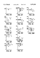
- FIGS. 3A through 3M The voltage profiles on the photoreceptor 10 depicting the multi-color image formation steps of the present invention as described with reference to FIGS. 1 and 2, are illustrated in FIGS. 3A through 3M. It is understood, however, that the voltages depicted with reference to FIGS. 3A through 3M are illustrative only, and that other voltage levels could be used with the single positive recharge step of the present invention.
- FIG. 3A illustrates the voltage profile 68 on photoreceptor belt 10 after the belt surface has been uniformly charged. The photoreceptor is initially charged to a voltage slightly higher than the -500 volts indicated (V o ) but after dark decay the V ddp voltage level is -500 volts. After a first exposure as illustrated in FIG.
- the voltage profile comprises high and low absolute voltage levels 74 and 72, respectively.
- the level 74 at the original -500 volts represents the background area for the first image development step, and the level 72 at -150 volts (FIG. 3B) represents the area discharged by the laser 24 and corresponds to the image area to be developed by a single color toner.
- black colored toner adheres to the DAD image area and causes the photoreceptor in the image area to be increased to approximately -275 volts (FIG. 3C).
- the toner particles 73 have a negative charge 75 associated therewith.
- corona recharge device 36 charges both regions 73 and 74 to a slightly higher level, e.g. -600 volts, than the original V ddp of -500 volts.
- those image areas to be developed with the next color toner are discharged to approximately -400 volts.
- a second development step of a first non-black color toner, e.g. yellow as illustrated in FIG. 3F, the yellow colored toner adheres to the DAD image area and causes the photoreceptor in the image area to be increased to approximately -500 volts (FIG. 3F).
- the yellow toner particles 73 have a negative charge 75 and a residual voltage V t associated therewith.
- corona recharge device 51 delivers a positive current to the image areas 73 and background areas 74 of the photoreceptor, whereby both areas are brought to a uniform and lower absolute level of, for example -300 volts.
- This single positive recharge step of the present invention enables a substantial reduction of the residual voltage V t associated with the toner image 73, without having to apply a negative charge to the toner layer.
- the difference between the potential associated with the developed image 73 before the single positive recharge step (FIG. 3G) and the photoreceptor potential after recharge (-300 volts) should be adequate to ensure that sufficient positive charge is applied to the negatively charged image 73 during recharge, and is preferably in the range of 100 to 350 volts.
- the image areas to be developed with the next color toner are discharged in superimposed registration with either previously toned areas or bare untoned areas, depending on the particular color sequencing of the full color image to be reproduced. Those previously untoned image areas to be developed with the next color toner are discharged to approximately -30 volts. Previously toned areas are discharged to a level increased by its associated V t .
- a third development step of a second non-black color toner, e.g. magenta as illustrated in FIG. 31, the magenta colored toner adheres to the DAD image area and causes the photoreceptor in the image area to be increased to approximately -100 volts.
- the magenta toner particles 73 have a negative charge 75 and a residual voltage V t associated therewith.
- the toned regions 73 and untoned regions 74 of the photoreceptor are then subjected to the first recharging step (FIG. 3J) of the split recharge process described with reference to FIG. 1.
- the first corona recharge device 61 overcharges the toned 73 and background areas 74 of the photoreceptor to a negatively higher level than V o or the ultimately desired V ddp .
- the photoreceptor surface having the developed image thereon is charged to approximately -600 volts and the toner particles 73 still have a negative charge 75 and a residual voltage V t associated therewith.
- the second corona recharge device 62 is a voltage sensitive device that delivers an alternating current to the photoreceptor surface to lower the photoreceptor potential to a uniform level of approximately V ddp of -400 volts (FIG. 3K) and substantially neutralizes the toner particles 73.
- a minimal residual voltage V t is associated with the developed image.
- a voltage sensitive corona recharge device whose graph of the output current (I) to the photoreceptor surface as a function of the voltage to the photoreceptor surface (V) has a high characteristic (I/V) slope, used for recharging a photoreceptor having a toner image developed thereon, is described in copending application for U.S. Patent titled "Method and Apparatus for Reduced Residual Toner Voltage", Ser. No. 08/347,616 having a common assignee as the present application, the relevant portions of which are hereby incorporated by reference herein.
- the photoreceptor After this split recharge step (FIGS. 3J and 3K), the photoreceptor is uniformly charged, the residual toner voltage associated with the previously developed toner layer is substantially reduced, and the toner charge at the top of the toner layer is substantially neutralized.
- the photoreceptor is again ready for image formation thereon.
- those bare areas and image areas 79 to be developed thereon by a fourth color (third non-black color) toner are discharged by an exposure device.
- Those previously untoned image areas to be developed with the next color toner are discharged to approximately -100 volts.
- Previously toned areas are discharged to a level increased by its associated V t .
- Development of those image areas 79 raises the associated voltage to approximately -300 volts.
Landscapes
- Physics & Mathematics (AREA)
- General Physics & Mathematics (AREA)
- Color Electrophotography (AREA)
- Electrostatic Charge, Transfer And Separation In Electrography (AREA)
Abstract
Description
Claims (24)
Priority Applications (2)
| Application Number | Priority Date | Filing Date | Title |
|---|---|---|---|
| US08/363,081 US5579100A (en) | 1994-12-23 | 1994-12-23 | Single positive recharge method and apparatus for color image formation |
| JP7328446A JPH08234523A (en) | 1994-12-23 | 1995-12-18 | Corona generation apparatus for reelectrification |
Applications Claiming Priority (1)
| Application Number | Priority Date | Filing Date | Title |
|---|---|---|---|
| US08/363,081 US5579100A (en) | 1994-12-23 | 1994-12-23 | Single positive recharge method and apparatus for color image formation |
Publications (1)
| Publication Number | Publication Date |
|---|---|
| US5579100A true US5579100A (en) | 1996-11-26 |
Family
ID=23428707
Family Applications (1)
| Application Number | Title | Priority Date | Filing Date |
|---|---|---|---|
| US08/363,081 Expired - Lifetime US5579100A (en) | 1994-12-23 | 1994-12-23 | Single positive recharge method and apparatus for color image formation |
Country Status (2)
| Country | Link |
|---|---|
| US (1) | US5579100A (en) |
| JP (1) | JPH08234523A (en) |
Cited By (11)
| Publication number | Priority date | Publication date | Assignee | Title |
|---|---|---|---|---|
| US5749034A (en) * | 1997-01-21 | 1998-05-05 | Xerox Corporation | Transfer, cleaning and imaging stations spaced within an interdocument zone |
| US5778289A (en) * | 1997-07-14 | 1998-07-07 | Xerox Corporation | D.C. recharge to reduce cross contamination in the read IOI process |
| US5778288A (en) * | 1997-07-14 | 1998-07-07 | Xerox Corporation | Erase before A.C. recharge in color electrographic printing |
| US5781839A (en) * | 1996-03-05 | 1998-07-14 | Ricoh Company, Ltd. | Multicolor image forming apparatus |
| US5794106A (en) * | 1997-07-14 | 1998-08-11 | Xerox Corporation | Erase before D.C. recharge in color electrophotographic printing |
| US5862438A (en) * | 1998-08-06 | 1999-01-19 | Xerox Corporation | Reduced interdocument zone in a printing system having a single developer power supply |
| US5926674A (en) * | 1998-01-08 | 1999-07-20 | Xerox Corporation | Reverse polarity split recharge in recharge-expose-and-develop image on imaging printing |
| US5991579A (en) * | 1998-11-23 | 1999-11-23 | Xerox Corporation | High slope DC/AC combination charging device |
| US20060205506A1 (en) * | 2001-10-26 | 2006-09-14 | Konami Corporation | Game machine, game system, control method for the game machine, control method for the game system and program |
| WO2008101757A2 (en) * | 2007-02-22 | 2008-08-28 | OCé PRINTING SYSTEMS GMBH | Method and assembly for creating printed images lying adjacent to one another on a print material with the aid of an electrophotographic printing device |
| CN105974761A (en) * | 2015-03-10 | 2016-09-28 | 富士施乐株式会社 | Image forming apparatus and method |
Citations (15)
| Publication number | Priority date | Publication date | Assignee | Title |
|---|---|---|---|---|
| US4033688A (en) * | 1975-02-14 | 1977-07-05 | Agfa-Gevaert, Aktiengesellschaft | Color copying apparatus |
| US4141648A (en) * | 1976-12-15 | 1979-02-27 | International Business Machines Corporation | Photoconductor charging technique |
| US4432631A (en) * | 1976-12-15 | 1984-02-21 | International Business Machines Corporation | Photoconductor charging technique |
| JPS6050553A (en) * | 1983-08-30 | 1985-03-20 | Fujitsu Ltd | Multicolor electronic recording method |
| US4660059A (en) * | 1985-11-25 | 1987-04-21 | Xerox Corporation | Color printing machine |
| US4761669A (en) * | 1987-05-21 | 1988-08-02 | Xerox Corporation | Highlight color printing |
| US4791452A (en) * | 1986-10-28 | 1988-12-13 | Kabushiki Kaisha Toshiba | Image forming apparatus having at least two-color image print function and method for controlling the same |
| US4819028A (en) * | 1986-10-08 | 1989-04-04 | Nec Corporation | Electrophotographic recording apparatus for forming a multicolor image |
| US4833503A (en) * | 1987-12-28 | 1989-05-23 | Xerox Corporation | Electronic color printing system with sonic toner release development |
| US4868611A (en) * | 1987-12-10 | 1989-09-19 | Xerox Corporation | Highlight color imaging with first image neutralization using a scorotron |
| US5061969A (en) * | 1990-07-02 | 1991-10-29 | Xerox Corporation | Hybrid development scheme for trilevel xerography |
| US5208636A (en) * | 1992-03-23 | 1993-05-04 | Xerox Corporation | Highlight color printing machine |
| US5241356A (en) * | 1992-07-29 | 1993-08-31 | Xerox Corporation | Method and apparatus for minimizing the voltage difference between a developed electrostatic image area and a latent electrostaic non-developed image |
| US5258820A (en) * | 1992-07-29 | 1993-11-02 | Xerox Corporation | Pre-recharge device for voltage uniformity in read color systems |
| US5438401A (en) * | 1991-12-09 | 1995-08-01 | Ricoh Company, Ltd. | Multicolor image forming method and apparatus therefor |
-
1994
- 1994-12-23 US US08/363,081 patent/US5579100A/en not_active Expired - Lifetime
-
1995
- 1995-12-18 JP JP7328446A patent/JPH08234523A/en not_active Withdrawn
Patent Citations (15)
| Publication number | Priority date | Publication date | Assignee | Title |
|---|---|---|---|---|
| US4033688A (en) * | 1975-02-14 | 1977-07-05 | Agfa-Gevaert, Aktiengesellschaft | Color copying apparatus |
| US4141648A (en) * | 1976-12-15 | 1979-02-27 | International Business Machines Corporation | Photoconductor charging technique |
| US4432631A (en) * | 1976-12-15 | 1984-02-21 | International Business Machines Corporation | Photoconductor charging technique |
| JPS6050553A (en) * | 1983-08-30 | 1985-03-20 | Fujitsu Ltd | Multicolor electronic recording method |
| US4660059A (en) * | 1985-11-25 | 1987-04-21 | Xerox Corporation | Color printing machine |
| US4819028A (en) * | 1986-10-08 | 1989-04-04 | Nec Corporation | Electrophotographic recording apparatus for forming a multicolor image |
| US4791452A (en) * | 1986-10-28 | 1988-12-13 | Kabushiki Kaisha Toshiba | Image forming apparatus having at least two-color image print function and method for controlling the same |
| US4761669A (en) * | 1987-05-21 | 1988-08-02 | Xerox Corporation | Highlight color printing |
| US4868611A (en) * | 1987-12-10 | 1989-09-19 | Xerox Corporation | Highlight color imaging with first image neutralization using a scorotron |
| US4833503A (en) * | 1987-12-28 | 1989-05-23 | Xerox Corporation | Electronic color printing system with sonic toner release development |
| US5061969A (en) * | 1990-07-02 | 1991-10-29 | Xerox Corporation | Hybrid development scheme for trilevel xerography |
| US5438401A (en) * | 1991-12-09 | 1995-08-01 | Ricoh Company, Ltd. | Multicolor image forming method and apparatus therefor |
| US5208636A (en) * | 1992-03-23 | 1993-05-04 | Xerox Corporation | Highlight color printing machine |
| US5241356A (en) * | 1992-07-29 | 1993-08-31 | Xerox Corporation | Method and apparatus for minimizing the voltage difference between a developed electrostatic image area and a latent electrostaic non-developed image |
| US5258820A (en) * | 1992-07-29 | 1993-11-02 | Xerox Corporation | Pre-recharge device for voltage uniformity in read color systems |
Cited By (13)
| Publication number | Priority date | Publication date | Assignee | Title |
|---|---|---|---|---|
| US5781839A (en) * | 1996-03-05 | 1998-07-14 | Ricoh Company, Ltd. | Multicolor image forming apparatus |
| US5749034A (en) * | 1997-01-21 | 1998-05-05 | Xerox Corporation | Transfer, cleaning and imaging stations spaced within an interdocument zone |
| US5778289A (en) * | 1997-07-14 | 1998-07-07 | Xerox Corporation | D.C. recharge to reduce cross contamination in the read IOI process |
| US5778288A (en) * | 1997-07-14 | 1998-07-07 | Xerox Corporation | Erase before A.C. recharge in color electrographic printing |
| US5794106A (en) * | 1997-07-14 | 1998-08-11 | Xerox Corporation | Erase before D.C. recharge in color electrophotographic printing |
| US5926674A (en) * | 1998-01-08 | 1999-07-20 | Xerox Corporation | Reverse polarity split recharge in recharge-expose-and-develop image on imaging printing |
| US5862438A (en) * | 1998-08-06 | 1999-01-19 | Xerox Corporation | Reduced interdocument zone in a printing system having a single developer power supply |
| US5991579A (en) * | 1998-11-23 | 1999-11-23 | Xerox Corporation | High slope DC/AC combination charging device |
| US20060205506A1 (en) * | 2001-10-26 | 2006-09-14 | Konami Corporation | Game machine, game system, control method for the game machine, control method for the game system and program |
| WO2008101757A2 (en) * | 2007-02-22 | 2008-08-28 | OCé PRINTING SYSTEMS GMBH | Method and assembly for creating printed images lying adjacent to one another on a print material with the aid of an electrophotographic printing device |
| WO2008101757A3 (en) * | 2007-02-22 | 2008-10-16 | Oce Printing Systems Gmbh | Method and assembly for creating printed images lying adjacent to one another on a print material with the aid of an electrophotographic printing device |
| CN105974761A (en) * | 2015-03-10 | 2016-09-28 | 富士施乐株式会社 | Image forming apparatus and method |
| US9690225B2 (en) * | 2015-03-10 | 2017-06-27 | Fuji Xerox Co., Ltd. | Image forming apparatus and method |
Also Published As
| Publication number | Publication date |
|---|---|
| JPH08234523A (en) | 1996-09-13 |
Similar Documents
| Publication | Publication Date | Title |
|---|---|---|
| US5258820A (en) | Pre-recharge device for voltage uniformity in read color systems | |
| US5600430A (en) | Split recharge method and apparatus for color image formation | |
| US5241356A (en) | Method and apparatus for minimizing the voltage difference between a developed electrostatic image area and a latent electrostaic non-developed image | |
| US4761672A (en) | Ramped developer biases | |
| US5537198A (en) | Double split recharge method and apparatus for color image formation | |
| US5581330A (en) | Method and apparatus for reducing residual toner voltage | |
| US5579100A (en) | Single positive recharge method and apparatus for color image formation | |
| US5613176A (en) | Image on image process color with two black development steps | |
| JPH0934222A (en) | Corona generator and printing press | |
| US6167224A (en) | Method for applying uniform gloss over the entire print | |
| CA2044319C (en) | Highlight printing apparatus | |
| US5038177A (en) | Selective pre-transfer corona transfer with light treatment for tri-level xerography | |
| EP0747778A2 (en) | Method of producing a color image | |
| US5583629A (en) | Color electrophotographic printing machine | |
| US4959286A (en) | Two-pass highlight color imaging with developer housing bias switching | |
| US5574541A (en) | Corona dual-use for color image formation | |
| US5613172A (en) | Hybrid DC recharge method and apparatus for split recharge imaging | |
| US5579089A (en) | Method and apparatus for reducing transferred background toner | |
| US5515155A (en) | Method and apparatus for establishing exposure and developer set points for color image formation | |
| US5480751A (en) | Tri-level background suppression scheme using an AC scorotron with front erase | |
| US5991579A (en) | High slope DC/AC combination charging device | |
| US6292645B1 (en) | Apparatus and method for minimizing the halo effect in an electrostatographic printing system | |
| US5666612A (en) | Roller to press the image toner on the photoreceptor | |
| US5410395A (en) | Means for controlling trilevel inter housing scorotron charging level | |
| EP0892318B1 (en) | Method of operating a colour printing machine |
Legal Events
| Date | Code | Title | Description |
|---|---|---|---|
| AS | Assignment |
Owner name: XEROX CORPORATION, CONNECTICUT Free format text: ASSIGNMENT OF ASSIGNORS INTEREST;ASSIGNORS:YU, ZHAO-ZHI;TABB, CHARLES H.;O'BRIEN, JOHN F.;AND OTHERS;REEL/FRAME:007296/0126;SIGNING DATES FROM 19941214 TO 19941219 |
|
| STCF | Information on status: patent grant |
Free format text: PATENTED CASE |
|
| FPAY | Fee payment |
Year of fee payment: 4 |
|
| AS | Assignment |
Owner name: BANK ONE, NA, AS ADMINISTRATIVE AGENT, ILLINOIS Free format text: SECURITY INTEREST;ASSIGNOR:XEROX CORPORATION;REEL/FRAME:013153/0001 Effective date: 20020621 |
|
| AS | Assignment |
Owner name: JPMORGAN CHASE BANK, AS COLLATERAL AGENT, TEXAS Free format text: SECURITY AGREEMENT;ASSIGNOR:XEROX CORPORATION;REEL/FRAME:015134/0476 Effective date: 20030625 Owner name: JPMORGAN CHASE BANK, AS COLLATERAL AGENT,TEXAS Free format text: SECURITY AGREEMENT;ASSIGNOR:XEROX CORPORATION;REEL/FRAME:015134/0476 Effective date: 20030625 |
|
| FPAY | Fee payment |
Year of fee payment: 8 |
|
| FPAY | Fee payment |
Year of fee payment: 12 |
|
| AS | Assignment |
Owner name: XEROX CORPORATION, CONNECTICUT Free format text: RELEASE BY SECURED PARTY;ASSIGNOR:JPMORGAN CHASE BANK, N.A. AS SUCCESSOR-IN-INTEREST ADMINISTRATIVE AGENT AND COLLATERAL AGENT TO JPMORGAN CHASE BANK;REEL/FRAME:066728/0193 Effective date: 20220822 |