US5574627A - Apparatus for preventing the formation of condensation on sub-cooled integrated circuit devices - Google Patents
Apparatus for preventing the formation of condensation on sub-cooled integrated circuit devices Download PDFInfo
- Publication number
- US5574627A US5574627A US08/506,155 US50615595A US5574627A US 5574627 A US5574627 A US 5574627A US 50615595 A US50615595 A US 50615595A US 5574627 A US5574627 A US 5574627A
- Authority
- US
- United States
- Prior art keywords
- integrated circuit
- circuit device
- thermal insulator
- printed circuit
- circuit board
- Prior art date
- Legal status (The legal status is an assumption and is not a legal conclusion. Google has not performed a legal analysis and makes no representation as to the accuracy of the status listed.)
- Expired - Lifetime
Links
Images


Classifications
-
- H—ELECTRICITY
- H01—ELECTRIC ELEMENTS
- H01L—SEMICONDUCTOR DEVICES NOT COVERED BY CLASS H10
- H01L23/00—Details of semiconductor or other solid state devices
- H01L23/34—Arrangements for cooling, heating, ventilating or temperature compensation ; Temperature sensing arrangements
- H01L23/46—Arrangements for cooling, heating, ventilating or temperature compensation ; Temperature sensing arrangements involving the transfer of heat by flowing fluids
- H01L23/473—Arrangements for cooling, heating, ventilating or temperature compensation ; Temperature sensing arrangements involving the transfer of heat by flowing fluids by flowing liquids
-
- H—ELECTRICITY
- H01—ELECTRIC ELEMENTS
- H01L—SEMICONDUCTOR DEVICES NOT COVERED BY CLASS H10
- H01L2924/00—Indexing scheme for arrangements or methods for connecting or disconnecting semiconductor or solid-state bodies as covered by H01L24/00
- H01L2924/0001—Technical content checked by a classifier
- H01L2924/0002—Not covered by any one of groups H01L24/00, H01L24/00 and H01L2224/00
Definitions
- the present invention relates to cooling systems for computer systems and, more particularly, to means for preventing the formation of condensation on cooled components within a computer system.
- CMOS complementary metal oxide semiconductor
- CPU central processor unit
- Cooling arrangements must be provided to prevent damage to these integrated circuits from the high temperatures generated by the devices.
- CMOS circuit In addition to cooling to prevent damage resulting from overheating, it is known that a CMOS circuit will operate at higher clock speeds as the circuit temperature is lowered. In some cases the processor frequency of CMOS processor has been improved to near 300% through the cooling of the processor die to a temperature of approximately -200° C.
- Many methods for sub-cooling processors and other computer components are known.
- One such cooling system comprises a plurality of hollow cold plates which are attached to the processors, modules or other components to be cooled. A liquid coolant is circulated from a refrigeration unit through connecting conduits to the cold plates to effectuate cooling of the attached components.
- cooling methods include directing a cooling airflow onto components requiring cooling, sealing the computer cabinetry and refrigerating the interior of the cabinet, immersing components in a coolant such as liquid nitrogen, or interfacing components with a Peltier TEC (thermal electric cooling) device.
- a coolant such as liquid nitrogen
- Peltier TEC thermo electric cooling
- Cooling of components to a temperature less than the local dew point presents certain difficulties in that condensation may form on the cold elements of the cooling system, such as the conduits, cold plates, sub-cooled components and structures to which the elements of the cooling system or the sub-cooled components are attached. This condensation can cause temporary or permanent damage to electrical components within the computer system.
- the need for minimizing signal path lengths and component spacing precludes the use of appropriately thick insulators between printed circuit boards or other sub-cooled components that is required to prevent the formation of condensation.
- frost or condensation within computer cabinetry can cause temporary or permanent damage to electrical components within the computer system.
- insulation around integrated circuit devices, such as processors and other integrated circuit devices, which are cooled to a temperature below the dew point of the ambient environment within the computer cabinetry to prevent the formation of frost or condensation is not practical since it would require increased spacing between components within the cabinetry and possibly larger cabinetry for the computer system.
- insulation packaging for a sub-cooled integrated circuit device.
- This packaging comprising a thermal insulator encasing the integrated circuit device together with cooling system elements affixed to the integrated circuit device.
- the thermal insulation has an inner surface applied to the integrated circuit device and elements of the cooling system in contact with the integrated circuit device, and an outer surface exposed to the ambient environment.
- sections of the insulator are made thinner than required to prevent the outer surface of the insulator from being cooled to a temperature below the dew point of the ambient environment.
- a heating element is provided to portions of the outer surface of the insulator, which portions of said outer surface are cooler than the dew point to prevent the formation of condensation.
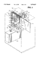
- FIG. 1 is a perspective view of a processor cabinet including a plurality of printed circuit boards and refrigeration system for cooling printed circuit board components.
- FIG. 2 is a printed circuit board subassembly, shown in perspective view, including two CPUs and corresponding CPU heat exchanger components of the cooling system shown in FIG. 1
- FIG. 3 is a perspective view, partially cut away, of a sub-cooled integrated circuit device including structure for insulating and preventing condensation on the sub-cooled integrated circuit device in accordance with the present invention.
- FIG. 1 there is seen a typical processor cabinet 102, shown in outline, which houses the components of a multiple processor computer system and includes a cooling system in accordance with the present invention. However, only those components necessary for an understanding of the present invention are shown and discussed herein.
- the processor cabinetry may additionally house disk drives, power supplies, memory boards and other structures not shown in FIG. 1.
- the computer system includes a plurality of processor boards, four of which are shown. These boards, identified by reference numerals 104, 106, 108 and 110, each include electrical contacts along one edge which are press fitted into mating connectors secured to the surface of a system backpanel 112. The backpanel provides common connections for the transmission of power, control and data signals between the various components of the computer system.
- the processor boards which will be described in greater detail below with reference to FIG. 2, each include two processors 114. Also shown in FIG. 1 is a typical fan panel 122 that generates an air flow directed upward across the processor boards and other components within the cabinet.
- the primary components of the cooling system shown in FIG. 1 include a refrigeration compressor unit 116, a heat exchanger 118 affixed to each processor 114, and refrigeration supply and return conduits 120 and 121, respectively, connecting each heat exchanger 118 with refrigeration compressor unit 116.
- the refrigeration compressor unit may be a single or two compressor compound, or cascade, vapor compression phase system which is located in the bottom of cabinet 102 to facilitate disconnection of the compressor unit from the conduit system for removal and service or replacement.
- the refrigeration compressor system provides pressurized coolant to each of the heat exchangers.
- Processor board 104 is shown in perspective view in FIG. 2.
- the processor board is a printed circuit board to which is attached two CPUs, identified by reference numerals 114A and 114B, respectively, as well as other circuit elements which are not shown. It should be noted that although the processor boards are shown including two CPUs, one, two or more processors can be accommodated on each processor board and the cooling system, described herein, designed accordingly. Attached to each CPU is a heat exchanger, identified by reference numerals 118A and 118B, respectively.
- Refrigerant supply conduits 120A and 120B each terminate into respective heat exchanger assemblies 118A and 118B to provide for the delivery of pressurized liquid coolant from the refrigeration compressor 116 to the heat exchanger assemblies, while refrigerant return conduits 121A and 121B provide for the return of coolant from respective heat exchanger assemblies 118A and 118B to the refrigeration compressor unit 116.
- the outside diameter of the refrigerant supply conduits is about 1/16 of an inch, much smaller than the diameter of the refrigerant return conduits, which have an outside diameter of about 3/8 of an inch.
- Chilled component surfaces susceptible to the formation of condensation or frost within the system shown in FIGS. 1 and 2 include compressor unit 116, refrigerant supply and return conduits 120 and 121, heat exchangers 118, integrated circuit devices (CPUs) 114, and those portions of printed circuit boards 104, 106, 108 and 110 which are in contact with integrated circuit devices 114.
- FIG. 3 is a perspective view, partially cut away, of a sub-cooled integrated circuit device.
- CPU 114 including structure for insulating and preventing condensation on CPU 114 in accordance with the present invention.
- CPU 114 is shown plugged into a socket assembly 116 which is permanently soldered to printed circuit board 106.
- Socket pins 115 extend from socket assembly 116 into and through printed circuit board 106.
- Heat exchanger 118 is secured to the upper surface of CPU 114, a thermal compound 140 provided between the CPU and heat exchanger to improve thermal conductivity between the two components.
- the CPU/heat exchanger assembly is thermally insulated from the ambient environment by insulation which encases the assembly.
- Upper insulator 130 covers CPU 114, socket assembly 116, heat exchanger 118 and all other components mounted to the top surface of printed circuit board 106.
- Lower insulator 132 is provided on the bottom surface of printed circuit board 106 to cover the socket pins 115. Socket pins 115, which protrude through the board, are chilled through thermal contact with the CPU pins.
- the insulators 130 and 132 are each seen to comprise a thin section of insulation above and below the CPU and heat exchanger, while the insulation around the perimeter of the CPU and heat exchanger is substantially thicker than the insulation above and below the CPU and heat exchanger.
- the thin sections of insulation above and below the CPU and heat exchanger are required to permit close spacing of multiple printed circuit boards within the processor cabinetry. However, at significantly low temperatures the thin sections of insulation do not provide thermal isolation adequate enough to prevent the formation of condensation on the cool, outside, surfaces of the thin sections.
- integral surface heaters 150 and 152 are provided on the top surface of upper insulator 130, and the lower surface of insulator 132, respectively.
- An additional surface heater 154 may also be provided between upper insulator 130 and printed circuit board 106 to prevent the formation of condensation on the printed circuit board surfaces adjacent the cooled CPU and heat exchanger assembly.
- These integral surface heaters may be implemented in several ways. The heaters may be commercially available custom etched resistive conductors on an insulative substrate which could be adhesively bonded to the insulator surfaces, or imbedded in the insulation. Alternatively, the integral surface heaters can be small gauge resistive wires arranged in a suitable pattern and secured to the insulator surfaces with double-sided adhesive tape. Semiconductive-elastomeric rubber or other semi-conductive compounds may also be employed within the integral surface heaters.
- Surface heaters 150, 152 and 154 generate heat upon the application of an electrical current thereto to prevent the formation of condensation on the surfaces of the insulators. Electric current may be provided to the integral surface heaters 150, 152 and 154 from already available printed circuit board power supply (not shown). An interlock circuit may optionally be included in the current supply circuitry to the heaters to prevent overheating should the CPU cooling system fails or be disabled.
- Insulators 130 and 132 and surface heating elements 150, 152 and 154 have omitted from FIGS. 1 and 2 for clarity.
Abstract
Description
Claims (6)
Priority Applications (1)
| Application Number | Priority Date | Filing Date | Title |
|---|---|---|---|
| US08/506,155 US5574627A (en) | 1995-07-24 | 1995-07-24 | Apparatus for preventing the formation of condensation on sub-cooled integrated circuit devices |
Applications Claiming Priority (1)
| Application Number | Priority Date | Filing Date | Title |
|---|---|---|---|
| US08/506,155 US5574627A (en) | 1995-07-24 | 1995-07-24 | Apparatus for preventing the formation of condensation on sub-cooled integrated circuit devices |
Publications (1)
| Publication Number | Publication Date |
|---|---|
| US5574627A true US5574627A (en) | 1996-11-12 |
Family
ID=24013427
Family Applications (1)
| Application Number | Title | Priority Date | Filing Date |
|---|---|---|---|
| US08/506,155 Expired - Lifetime US5574627A (en) | 1995-07-24 | 1995-07-24 | Apparatus for preventing the formation of condensation on sub-cooled integrated circuit devices |
Country Status (1)
| Country | Link |
|---|---|
| US (1) | US5574627A (en) |
Cited By (52)
| Publication number | Priority date | Publication date | Assignee | Title |
|---|---|---|---|---|
| US5710733A (en) * | 1996-01-22 | 1998-01-20 | Silicon Graphics, Inc. | Processor-inclusive memory module |
| US5867419A (en) * | 1997-01-27 | 1999-02-02 | Silicon Graphics, Inc. | Processor-inclusive memory module |
| USD416872S (en) * | 1997-11-06 | 1999-11-23 | Zf Microsystems, Inc. | Single component computer |
| US6052284A (en) * | 1996-08-06 | 2000-04-18 | Advantest Corporation | Printed circuit board with electronic devices mounted thereon |
| US6054676A (en) * | 1998-02-09 | 2000-04-25 | Kryotech, Inc. | Method and apparatus for cooling an integrated circuit device |
| US6127663A (en) * | 1998-10-09 | 2000-10-03 | Ericsson Inc. | Electronics cabinet cooling system |
| US6144013A (en) * | 1999-07-01 | 2000-11-07 | International Business Machines Corporation | Local humidity control system for low temperature electronic module |
| US6152213A (en) * | 1997-03-27 | 2000-11-28 | Fujitsu Limited | Cooling system for electronic packages |
| US6192701B1 (en) | 1999-08-23 | 2001-02-27 | International Business Machines Corporation | Sealed multi-chip module cooling system |
| US6196002B1 (en) | 1999-06-24 | 2001-03-06 | Advanced Micro Devices, Inc. | Ball grid array package having thermoelectric cooler |
| WO2001025881A2 (en) | 1999-10-04 | 2001-04-12 | Asetek A/S | Computer system comprising a cooling system |
| US6243268B1 (en) * | 1999-10-12 | 2001-06-05 | International Business Machines Corporation | Cooled IC chip modules with an insulated circuit board |
| US6246581B1 (en) * | 1999-10-12 | 2001-06-12 | International Business Machines Corporation | Heated PCB interconnect for cooled IC chip modules |
| US6253835B1 (en) | 2000-02-11 | 2001-07-03 | International Business Machines Corporation | Isothermal heat sink with converging, diverging channels |
| US6262392B1 (en) * | 1997-10-13 | 2001-07-17 | Telefonaktiebolaget Lm Ericsson (Publ) | Printed circuit boards |
| US6292365B1 (en) * | 1998-09-18 | 2001-09-18 | Hitachi, Ltd. | Electronic apparatus |
| US6301109B1 (en) | 2000-02-11 | 2001-10-09 | International Business Machines Corporation | Isothermal heat sink with cross-flow openings between channels |
| US6337794B1 (en) | 2000-02-11 | 2002-01-08 | International Business Machines Corporation | Isothermal heat sink with tiered cooling channels |
| US6423940B1 (en) * | 2001-03-02 | 2002-07-23 | Agilent Technologies, Inc. | Temperature stabilization scheme for a circuit board |
| WO2002065549A1 (en) * | 2001-02-14 | 2002-08-22 | Chip-Con Aps | A cooling arrangement for an integrated circuit |
| US6483078B2 (en) | 2000-02-09 | 2002-11-19 | Oceanit Laboratories, Inc. | Moisture control system for electrical devices |
| US6486440B1 (en) * | 2001-07-09 | 2002-11-26 | Jds Uniphase Corporation | Redundant package for optical components |
| EP1261027A2 (en) * | 2001-05-24 | 2002-11-27 | Nec Corporation | Electronic device having dewing prevention structure |
| US6536510B2 (en) * | 2001-07-10 | 2003-03-25 | Thermal Corp. | Thermal bus for cabinets housing high power electronics equipment |
| US6543246B2 (en) | 2001-07-24 | 2003-04-08 | Kryotech, Inc. | Integrated circuit cooling apparatus |
| US20030111340A1 (en) * | 2001-12-18 | 2003-06-19 | Dionex Corporation | Disposable working electrode for an electrochemical cell |
| US6664511B2 (en) | 2001-07-09 | 2003-12-16 | Jds Uniphase Corporation | Package for optical components |
| US6668570B2 (en) | 2001-05-31 | 2003-12-30 | Kryotech, Inc. | Apparatus and method for controlling the temperature of an electronic device under test |
| US6697553B2 (en) | 2002-02-15 | 2004-02-24 | Jds Uniphase Corporation | Compact, low insertion loss, high yield arrayed waveguide grating |
| US20040155021A1 (en) * | 2003-02-06 | 2004-08-12 | Norton David G. | Flexible heater for heating electrical components in operator control handle |
| US6815643B2 (en) * | 2000-07-14 | 2004-11-09 | Infineon Technologies Ag | Semiconductor device with temperature regulation |
| US20050083656A1 (en) * | 2003-09-10 | 2005-04-21 | Hamman Brian A. | Liquid cooling system |
| US6975028B1 (en) | 2003-03-19 | 2005-12-13 | Delta Design, Inc. | Thermal apparatus for engaging electronic device |
| US20060067052A1 (en) * | 2004-09-30 | 2006-03-30 | Llapitan David J | Liquid cooling system |
| US20060090494A1 (en) * | 2004-11-01 | 2006-05-04 | Manole Dan M | Compact refrigeration system for providing multiple levels of cooling |
| US20070209379A1 (en) * | 2006-03-07 | 2007-09-13 | Lenhardt Ronald R J | Method and apparatus for cooling semiconductor chips |
| US20080106863A1 (en) * | 2005-01-10 | 2008-05-08 | Cohen Alan M | Heat dissipation assembly for computing devices |
| US20110056240A1 (en) * | 2009-09-08 | 2011-03-10 | Consolidated Edison Company Of New York, Inc. | Freeze plug system and method of operation |
| US20110079033A1 (en) * | 2008-06-12 | 2011-04-07 | Noriyuki Okuda | Air conditioner |
| US20120125586A1 (en) * | 2010-11-19 | 2012-05-24 | Inventec Corporation | Separable liquid-cooling heat-dissipation module |
| CN102478931A (en) * | 2010-11-23 | 2012-05-30 | 英业达股份有限公司 | Detachable liquid cooling heat dissipation module |
| US20140301037A1 (en) * | 2013-04-04 | 2014-10-09 | Green Revolution Cooling, Inc. | Liquid coolant-submersible node |
| US9504190B2 (en) | 2013-05-06 | 2016-11-22 | Green Revolution Cooling, Inc. | System and method of packaging computing resources for space and fire-resistance |
| US9756766B2 (en) | 2014-05-13 | 2017-09-05 | Green Revolution Cooling, Inc. | System and method for air-cooling hard drives in liquid-cooled server rack |
| US20180306204A1 (en) * | 2017-04-25 | 2018-10-25 | Shimadzu Corporation | Power source integrated vacuum pump |
| US10209003B2 (en) | 2012-02-21 | 2019-02-19 | Thermal Corp. | Electronics cabinet and rack cooling system and method |
| US11359865B2 (en) | 2018-07-23 | 2022-06-14 | Green Revolution Cooling, Inc. | Dual Cooling Tower Time Share Water Treatment System |
| US20230086534A1 (en) * | 2021-09-23 | 2023-03-23 | Baidu Usa Llc | Bidirectional connector for server liquid cooling |
| USD982145S1 (en) | 2020-10-19 | 2023-03-28 | Green Revolution Cooling, Inc. | Cooling system enclosure |
| USD998770S1 (en) | 2020-10-19 | 2023-09-12 | Green Revolution Cooling, Inc. | Cooling system enclosure |
| US11805624B2 (en) | 2021-09-17 | 2023-10-31 | Green Revolution Cooling, Inc. | Coolant shroud |
| US11925946B2 (en) | 2022-03-28 | 2024-03-12 | Green Revolution Cooling, Inc. | Fluid delivery wand |
Citations (6)
| Publication number | Priority date | Publication date | Assignee | Title |
|---|---|---|---|---|
| US3289046A (en) * | 1964-05-19 | 1966-11-29 | Gen Electric | Component chip mounted on substrate with heater pads therebetween |
| US4374316A (en) * | 1979-08-29 | 1983-02-15 | Kyoto Ceramic Co., Ltd. | Semiconductor integrated circuit supporter having a heating element |
| US4739382A (en) * | 1985-05-31 | 1988-04-19 | Tektronix, Inc. | Package for a charge-coupled device with temperature dependent cooling |
| US4897762A (en) * | 1987-07-22 | 1990-01-30 | Hitachi, Ltd. | Cooling system and method for electronic circuit devices |
| US5331273A (en) * | 1992-04-10 | 1994-07-19 | The United States Of America As Represented By The Secretary Of The Navy | Thermal fixture for testing an integrated circuit |
| US5365749A (en) * | 1993-12-23 | 1994-11-22 | Ncr Corporation | Computer component cooling system with local evaporation of refrigerant |
-
1995
- 1995-07-24 US US08/506,155 patent/US5574627A/en not_active Expired - Lifetime
Patent Citations (6)
| Publication number | Priority date | Publication date | Assignee | Title |
|---|---|---|---|---|
| US3289046A (en) * | 1964-05-19 | 1966-11-29 | Gen Electric | Component chip mounted on substrate with heater pads therebetween |
| US4374316A (en) * | 1979-08-29 | 1983-02-15 | Kyoto Ceramic Co., Ltd. | Semiconductor integrated circuit supporter having a heating element |
| US4739382A (en) * | 1985-05-31 | 1988-04-19 | Tektronix, Inc. | Package for a charge-coupled device with temperature dependent cooling |
| US4897762A (en) * | 1987-07-22 | 1990-01-30 | Hitachi, Ltd. | Cooling system and method for electronic circuit devices |
| US5331273A (en) * | 1992-04-10 | 1994-07-19 | The United States Of America As Represented By The Secretary Of The Navy | Thermal fixture for testing an integrated circuit |
| US5365749A (en) * | 1993-12-23 | 1994-11-22 | Ncr Corporation | Computer component cooling system with local evaporation of refrigerant |
Cited By (79)
| Publication number | Priority date | Publication date | Assignee | Title |
|---|---|---|---|---|
| US5710733A (en) * | 1996-01-22 | 1998-01-20 | Silicon Graphics, Inc. | Processor-inclusive memory module |
| US6052284A (en) * | 1996-08-06 | 2000-04-18 | Advantest Corporation | Printed circuit board with electronic devices mounted thereon |
| US5867419A (en) * | 1997-01-27 | 1999-02-02 | Silicon Graphics, Inc. | Processor-inclusive memory module |
| US6152213A (en) * | 1997-03-27 | 2000-11-28 | Fujitsu Limited | Cooling system for electronic packages |
| US6262392B1 (en) * | 1997-10-13 | 2001-07-17 | Telefonaktiebolaget Lm Ericsson (Publ) | Printed circuit boards |
| USD416872S (en) * | 1997-11-06 | 1999-11-23 | Zf Microsystems, Inc. | Single component computer |
| US6054676A (en) * | 1998-02-09 | 2000-04-25 | Kryotech, Inc. | Method and apparatus for cooling an integrated circuit device |
| US6292365B1 (en) * | 1998-09-18 | 2001-09-18 | Hitachi, Ltd. | Electronic apparatus |
| US6127663A (en) * | 1998-10-09 | 2000-10-03 | Ericsson Inc. | Electronics cabinet cooling system |
| US6196002B1 (en) | 1999-06-24 | 2001-03-06 | Advanced Micro Devices, Inc. | Ball grid array package having thermoelectric cooler |
| US6144013A (en) * | 1999-07-01 | 2000-11-07 | International Business Machines Corporation | Local humidity control system for low temperature electronic module |
| US6192701B1 (en) | 1999-08-23 | 2001-02-27 | International Business Machines Corporation | Sealed multi-chip module cooling system |
| WO2001025881A2 (en) | 1999-10-04 | 2001-04-12 | Asetek A/S | Computer system comprising a cooling system |
| WO2001025881A3 (en) * | 1999-10-04 | 2001-11-29 | Asetek As | Computer system comprising a cooling system |
| US6246581B1 (en) * | 1999-10-12 | 2001-06-12 | International Business Machines Corporation | Heated PCB interconnect for cooled IC chip modules |
| US6243268B1 (en) * | 1999-10-12 | 2001-06-05 | International Business Machines Corporation | Cooled IC chip modules with an insulated circuit board |
| US6483078B2 (en) | 2000-02-09 | 2002-11-19 | Oceanit Laboratories, Inc. | Moisture control system for electrical devices |
| US6337794B1 (en) | 2000-02-11 | 2002-01-08 | International Business Machines Corporation | Isothermal heat sink with tiered cooling channels |
| US6253835B1 (en) | 2000-02-11 | 2001-07-03 | International Business Machines Corporation | Isothermal heat sink with converging, diverging channels |
| US6301109B1 (en) | 2000-02-11 | 2001-10-09 | International Business Machines Corporation | Isothermal heat sink with cross-flow openings between channels |
| US6815643B2 (en) * | 2000-07-14 | 2004-11-09 | Infineon Technologies Ag | Semiconductor device with temperature regulation |
| US20040070927A1 (en) * | 2001-02-14 | 2004-04-15 | Morten Espersen | Cooling arrangement for an integrated circuit |
| WO2002065549A1 (en) * | 2001-02-14 | 2002-08-22 | Chip-Con Aps | A cooling arrangement for an integrated circuit |
| US7042723B2 (en) | 2001-02-14 | 2006-05-09 | Extreme Cooling Technology Aps | Cooling arrangement for an integrated circuit |
| CN100355062C (en) * | 2001-02-14 | 2007-12-12 | 希普根Aps公司 | A cooling arrangement for an integrated circuit |
| US6423940B1 (en) * | 2001-03-02 | 2002-07-23 | Agilent Technologies, Inc. | Temperature stabilization scheme for a circuit board |
| EP1261027A2 (en) * | 2001-05-24 | 2002-11-27 | Nec Corporation | Electronic device having dewing prevention structure |
| US20020175404A1 (en) * | 2001-05-24 | 2002-11-28 | Nec Corporation | Electronic device having dewing prevention structure and dewing prevention structure of electronic device |
| US6853071B2 (en) * | 2001-05-24 | 2005-02-08 | Nec Corporation | Electronic device having dewing prevention structure and dewing prevention structure of electronic device |
| EP1261027A3 (en) * | 2001-05-24 | 2005-05-11 | Nec Corporation | Electronic device having dewing prevention structure |
| US6668570B2 (en) | 2001-05-31 | 2003-12-30 | Kryotech, Inc. | Apparatus and method for controlling the temperature of an electronic device under test |
| US20040139756A1 (en) * | 2001-05-31 | 2004-07-22 | Wall Charles B. | Apparatus and method for controlling the temperature of an electronic device under test |
| US6993922B2 (en) | 2001-05-31 | 2006-02-07 | Delta Design, Inc. | Apparatus and method for controlling the temperature of an electronic device under test |
| US6664511B2 (en) | 2001-07-09 | 2003-12-16 | Jds Uniphase Corporation | Package for optical components |
| US6486440B1 (en) * | 2001-07-09 | 2002-11-26 | Jds Uniphase Corporation | Redundant package for optical components |
| US6536510B2 (en) * | 2001-07-10 | 2003-03-25 | Thermal Corp. | Thermal bus for cabinets housing high power electronics equipment |
| US6543246B2 (en) | 2001-07-24 | 2003-04-08 | Kryotech, Inc. | Integrated circuit cooling apparatus |
| US20030111340A1 (en) * | 2001-12-18 | 2003-06-19 | Dionex Corporation | Disposable working electrode for an electrochemical cell |
| US6697553B2 (en) | 2002-02-15 | 2004-02-24 | Jds Uniphase Corporation | Compact, low insertion loss, high yield arrayed waveguide grating |
| US6900411B2 (en) * | 2003-02-06 | 2005-05-31 | The Raymond Corporation | Flexible heater for heating electrical components in operator control handle |
| US20040155021A1 (en) * | 2003-02-06 | 2004-08-12 | Norton David G. | Flexible heater for heating electrical components in operator control handle |
| US20050280144A1 (en) * | 2003-03-19 | 2005-12-22 | Wayburn Lewis S | Thermal apparatus for engaging electronic device |
| US6975028B1 (en) | 2003-03-19 | 2005-12-13 | Delta Design, Inc. | Thermal apparatus for engaging electronic device |
| US7508672B2 (en) * | 2003-09-10 | 2009-03-24 | Qnx Cooling Systems Inc. | Cooling system |
| US20050083656A1 (en) * | 2003-09-10 | 2005-04-21 | Hamman Brian A. | Liquid cooling system |
| US7120021B2 (en) * | 2003-10-18 | 2006-10-10 | Qnx Cooling Systems Inc. | Liquid cooling system |
| US20050083657A1 (en) * | 2003-10-18 | 2005-04-21 | Qnx Cooling Systems, Inc. | Liquid cooling system |
| GB2433584A (en) * | 2004-09-30 | 2007-06-27 | Intel Corp | Liquid cooling system for multi-processor |
| GB2433584B (en) * | 2004-09-30 | 2010-03-17 | Intel Corp | Liquid cooling system for multi-processor |
| WO2006039611A1 (en) * | 2004-09-30 | 2006-04-13 | Intel Corporation | Liquid cooling system for multi-processor |
| US20060067052A1 (en) * | 2004-09-30 | 2006-03-30 | Llapitan David J | Liquid cooling system |
| US20060090494A1 (en) * | 2004-11-01 | 2006-05-04 | Manole Dan M | Compact refrigeration system for providing multiple levels of cooling |
| US7478541B2 (en) | 2004-11-01 | 2009-01-20 | Tecumseh Products Company | Compact refrigeration system for providing multiple levels of cooling |
| US20080106863A1 (en) * | 2005-01-10 | 2008-05-08 | Cohen Alan M | Heat dissipation assembly for computing devices |
| US7768782B2 (en) * | 2005-01-10 | 2010-08-03 | H. Christian Gunderson | Heat dissipation assembly for computing devices |
| US7551441B2 (en) * | 2005-01-10 | 2009-06-23 | H Christian Gunderson | Heat dissipation assembly for computing devices |
| US20090213539A1 (en) * | 2005-01-10 | 2009-08-27 | H Christian Gunderson | Heat disssipation assembly for computing devices |
| US20070209379A1 (en) * | 2006-03-07 | 2007-09-13 | Lenhardt Ronald R J | Method and apparatus for cooling semiconductor chips |
| US7412844B2 (en) | 2006-03-07 | 2008-08-19 | Blue Zone 40 Inc. | Method and apparatus for cooling semiconductor chips |
| US20110079033A1 (en) * | 2008-06-12 | 2011-04-07 | Noriyuki Okuda | Air conditioner |
| US8464548B2 (en) * | 2008-06-12 | 2013-06-18 | Daikin Industries, Ltd. | Air conditioner |
| US20110056240A1 (en) * | 2009-09-08 | 2011-03-10 | Consolidated Edison Company Of New York, Inc. | Freeze plug system and method of operation |
| US20120125586A1 (en) * | 2010-11-19 | 2012-05-24 | Inventec Corporation | Separable liquid-cooling heat-dissipation module |
| US8596338B2 (en) * | 2010-11-19 | 2013-12-03 | Inventec Corporation | Separable liquid-cooling heat-dissipation module |
| CN102478931A (en) * | 2010-11-23 | 2012-05-30 | 英业达股份有限公司 | Detachable liquid cooling heat dissipation module |
| US10209003B2 (en) | 2012-02-21 | 2019-02-19 | Thermal Corp. | Electronics cabinet and rack cooling system and method |
| US20140301037A1 (en) * | 2013-04-04 | 2014-10-09 | Green Revolution Cooling, Inc. | Liquid coolant-submersible node |
| US10624242B2 (en) | 2013-05-06 | 2020-04-14 | Green Revolution Cooling, Inc. | System and method of packaging computing resources for space and fire-resistance |
| US9504190B2 (en) | 2013-05-06 | 2016-11-22 | Green Revolution Cooling, Inc. | System and method of packaging computing resources for space and fire-resistance |
| US9756766B2 (en) | 2014-05-13 | 2017-09-05 | Green Revolution Cooling, Inc. | System and method for air-cooling hard drives in liquid-cooled server rack |
| US20180306204A1 (en) * | 2017-04-25 | 2018-10-25 | Shimadzu Corporation | Power source integrated vacuum pump |
| US10941787B2 (en) * | 2017-04-25 | 2021-03-09 | Shimadzu Corporation | Power source integrated vacuum pump having a power source with a substrate in contact with and covering a portion of a cooling surface which is also covered by a heat insulating plate |
| US11359865B2 (en) | 2018-07-23 | 2022-06-14 | Green Revolution Cooling, Inc. | Dual Cooling Tower Time Share Water Treatment System |
| USD982145S1 (en) | 2020-10-19 | 2023-03-28 | Green Revolution Cooling, Inc. | Cooling system enclosure |
| USD998770S1 (en) | 2020-10-19 | 2023-09-12 | Green Revolution Cooling, Inc. | Cooling system enclosure |
| US11805624B2 (en) | 2021-09-17 | 2023-10-31 | Green Revolution Cooling, Inc. | Coolant shroud |
| US20230086534A1 (en) * | 2021-09-23 | 2023-03-23 | Baidu Usa Llc | Bidirectional connector for server liquid cooling |
| US11792959B2 (en) * | 2021-09-23 | 2023-10-17 | Baidu Usa Llc | Bidirectional connector for server liquid cooling |
| US11925946B2 (en) | 2022-03-28 | 2024-03-12 | Green Revolution Cooling, Inc. | Fluid delivery wand |
Similar Documents
| Publication | Publication Date | Title |
|---|---|---|
| US5574627A (en) | Apparatus for preventing the formation of condensation on sub-cooled integrated circuit devices | |
| JP4410466B2 (en) | Electronic equipment | |
| US6581388B2 (en) | Active temperature gradient reducer | |
| US6243268B1 (en) | Cooled IC chip modules with an insulated circuit board | |
| US5918469A (en) | Cooling system and method of cooling electronic devices | |
| US5365749A (en) | Computer component cooling system with local evaporation of refrigerant | |
| CN108207097B (en) | Heat insulation device and electronic product | |
| US6101094A (en) | Printed circuit board with integrated cooling mechanism | |
| US6246581B1 (en) | Heated PCB interconnect for cooled IC chip modules | |
| US5251095A (en) | Low temperature conduction module for a cryogenically-cooled processor | |
| JP2004363308A (en) | Rack-mounted server system | |
| JP4023054B2 (en) | Electronic circuit unit | |
| US6233960B1 (en) | Spot cooling evaporator cooling system for integrated circuit chip modules | |
| US6710691B2 (en) | Transformer with an associated heat-dissipating plastic element | |
| US6853071B2 (en) | Electronic device having dewing prevention structure and dewing prevention structure of electronic device | |
| US6018460A (en) | Flexible thermal conductor with electromagnetic interference shielding capability for electronic components | |
| US6195257B1 (en) | Apparatus and method of adapting a rectifier module to enhance cooling | |
| EP0293435B1 (en) | Infrared detector with improved heat dissipation | |
| US11910572B2 (en) | Sealed communications module with multi-path thermal management system | |
| US6122926A (en) | Low thermal conductance insulated cooling assembly for IC chip modules | |
| KR200285745Y1 (en) | Heat exchanger unit | |
| JPH11145664A (en) | Cooling system for switchboard | |
| US6108204A (en) | CPU heat sink | |
| CN211478771U (en) | Heat abstractor and head-mounted display device | |
| US20240074091A1 (en) | Directed cooling in heat producing systems |
Legal Events
| Date | Code | Title | Description |
|---|---|---|---|
| AS | Assignment |
Owner name: AT&T GLOBAL INFORMATION SOLUTIONS COMPANY, OHIO Free format text: ASSIGNMENT OF ASSIGNORS INTEREST;ASSIGNOR:PORTER, WARREN W.;REEL/FRAME:007590/0538 Effective date: 19950705 |
|
| AS | Assignment |
Owner name: NCR CORPORATION, OHIO Free format text: ASSIGNMENT OF ASSIGNORS INTEREST;ASSIGNOR:AT&T GLOBAL INFORMATION SOLUTIONS COMPANY;REEL/FRAME:008047/0429 Effective date: 19960109 |
|
| STCF | Information on status: patent grant |
Free format text: PATENTED CASE |
|
| FPAY | Fee payment |
Year of fee payment: 4 |
|
| FPAY | Fee payment |
Year of fee payment: 8 |
|
| AS | Assignment |
Owner name: TERADATA US, INC., OHIO Free format text: ASSIGNMENT OF ASSIGNORS INTEREST;ASSIGNOR:NCR CORPORATION;REEL/FRAME:020540/0786 Effective date: 20070924 |
|
| REMI | Maintenance fee reminder mailed | ||
| AS | Assignment |
Owner name: JPMORGAN CHASE BANK, N.A., TEXAS Free format text: SECURITY AGREEMENT;ASSIGNOR:BE AEROSPACE, INC.;REEL/FRAME:021393/0273 Effective date: 20080728 Owner name: JPMORGAN CHASE BANK, N.A.,TEXAS Free format text: SECURITY AGREEMENT;ASSIGNOR:BE AEROSPACE, INC.;REEL/FRAME:021393/0273 Effective date: 20080728 |
|
| FPAY | Fee payment |
Year of fee payment: 12 |
|
| SULP | Surcharge for late payment |
Year of fee payment: 11 |
|
| AS | Assignment |
Owner name: B/E AEROSPACE, INC., FLORIDA Free format text: CHANGE OF NAME;ASSIGNOR:BE AEROSPACE, INC.;REEL/FRAME:031600/0945 Effective date: 20120730 |
|
| AS | Assignment |
Owner name: B/E AEROSPACE, INC., FLORIDA Free format text: RELEASE BY SECURED PARTY;ASSIGNOR:JP MORGAN CHASE BANK, N.A.;REEL/FRAME:034805/0718 Effective date: 20141216 |
|
| AS | Assignment |
Owner name: JPMORGAN CHASE BANK, N.A., NEW YORK Free format text: SECURITY INTEREST;ASSIGNOR:B/E AEROSPACE, INC.;REEL/FRAME:035176/0493 Effective date: 20141216 |
|
| AS | Assignment |
Owner name: B/E AEROSPACE, INC., FLORIDA Free format text: CORRECTIVE ASSIGNMENT TO CORRECT THE INCORRECT APPL. NO. 13/071,416 PREVIOUSLY RECORDED AT REEL: 031600 FRAME: 0945. ASSIGNOR(S) HEREBY CONFIRMS THE CHANGE OF NAME;ASSIGNOR:BE AEROSPACE, INC.;REEL/FRAME:036242/0530 Effective date: 20120730 |
|
| AS | Assignment |
Owner name: B/E AEROSPACE, INC., FLORIDA Free format text: RELEASE BY SECURED PARTY;ASSIGNOR:JP MORGAN CHASE BANK, N.A;REEL/FRAME:049209/0619 Effective date: 20170413 |