US5547176A - Apparatus and method for binding pseudo-signatures into a booklet - Google Patents
Apparatus and method for binding pseudo-signatures into a booklet Download PDFInfo
- Publication number
- US5547176A US5547176A US08/356,614 US35661494A US5547176A US 5547176 A US5547176 A US 5547176A US 35661494 A US35661494 A US 35661494A US 5547176 A US5547176 A US 5547176A
- Authority
- US
- United States
- Prior art keywords
- prints
- folded
- binding
- mode
- Prior art date
- Legal status (The legal status is an assumption and is not a legal conclusion. Google has not performed a legal analysis and makes no representation as to the accuracy of the status listed.)
- Expired - Lifetime
Links
- 238000000034 method Methods 0.000 title claims description 37
- 239000000758 substrate Substances 0.000 claims abstract description 32
- 239000012790 adhesive layer Substances 0.000 claims abstract description 19
- 239000000853 adhesive Substances 0.000 claims description 36
- 230000001070 adhesive effect Effects 0.000 claims description 36
- 239000000463 material Substances 0.000 claims description 11
- 239000000835 fiber Substances 0.000 claims description 7
- 239000011248 coating agent Substances 0.000 claims 1
- 238000000576 coating method Methods 0.000 claims 1
- 230000002401 inhibitory effect Effects 0.000 claims 1
- 230000008569 process Effects 0.000 description 18
- 238000012545 processing Methods 0.000 description 14
- 239000011230 binding agent Substances 0.000 description 7
- 238000003384 imaging method Methods 0.000 description 7
- 238000004513 sizing Methods 0.000 description 6
- 238000010586 diagram Methods 0.000 description 5
- 108091008695 photoreceptors Proteins 0.000 description 4
- 238000007788 roughening Methods 0.000 description 3
- 238000012546 transfer Methods 0.000 description 3
- 238000013459 approach Methods 0.000 description 2
- 230000005540 biological transmission Effects 0.000 description 2
- 230000009977 dual effect Effects 0.000 description 2
- 230000000694 effects Effects 0.000 description 2
- 238000009966 trimming Methods 0.000 description 2
- 230000009471 action Effects 0.000 description 1
- 238000004026 adhesive bonding Methods 0.000 description 1
- 238000003491 array Methods 0.000 description 1
- 230000009286 beneficial effect Effects 0.000 description 1
- 230000015572 biosynthetic process Effects 0.000 description 1
- 239000003086 colorant Substances 0.000 description 1
- 238000004891 communication Methods 0.000 description 1
- 230000006835 compression Effects 0.000 description 1
- 238000007906 compression Methods 0.000 description 1
- 238000010276 construction Methods 0.000 description 1
- 238000005336 cracking Methods 0.000 description 1
- 238000000354 decomposition reaction Methods 0.000 description 1
- 230000003247 decreasing effect Effects 0.000 description 1
- 238000012217 deletion Methods 0.000 description 1
- 230000037430 deletion Effects 0.000 description 1
- 238000001514 detection method Methods 0.000 description 1
- 238000001914 filtration Methods 0.000 description 1
- 230000006870 function Effects 0.000 description 1
- 238000010438 heat treatment Methods 0.000 description 1
- 230000002452 interceptive effect Effects 0.000 description 1
- 238000012986 modification Methods 0.000 description 1
- 230000004048 modification Effects 0.000 description 1
- 230000035515 penetration Effects 0.000 description 1
- 230000003134 recirculating effect Effects 0.000 description 1
- 230000009467 reduction Effects 0.000 description 1
- 238000012216 screening Methods 0.000 description 1
- 230000001360 synchronised effect Effects 0.000 description 1
- 238000012360 testing method Methods 0.000 description 1
Images


Classifications
-
- G—PHYSICS
- G03—PHOTOGRAPHY; CINEMATOGRAPHY; ANALOGOUS TECHNIQUES USING WAVES OTHER THAN OPTICAL WAVES; ELECTROGRAPHY; HOLOGRAPHY
- G03G—ELECTROGRAPHY; ELECTROPHOTOGRAPHY; MAGNETOGRAPHY
- G03G15/00—Apparatus for electrographic processes using a charge pattern
- G03G15/65—Apparatus which relate to the handling of copy material
- G03G15/6538—Devices for collating sheet copy material, e.g. sorters, control, copies in staples form
- G03G15/6541—Binding sets of sheets, e.g. by stapling, glueing
- G03G15/6544—Details about the binding means or procedure
-
- G—PHYSICS
- G03—PHOTOGRAPHY; CINEMATOGRAPHY; ANALOGOUS TECHNIQUES USING WAVES OTHER THAN OPTICAL WAVES; ELECTROGRAPHY; HOLOGRAPHY
- G03G—ELECTROGRAPHY; ELECTROPHOTOGRAPHY; MAGNETOGRAPHY
- G03G2215/00—Apparatus for electrophotographic processes
- G03G2215/00362—Apparatus for electrophotographic processes relating to the copy medium handling
- G03G2215/00789—Adding properties or qualities to the copy medium
- G03G2215/00822—Binder, e.g. glueing device
Definitions
- the present invention relates generally to a technique for binding a set of N-up prints and, more particularly, to an apparatus and method in which each of the N-up prints are folded individually and an adhesive layer is applied to each folded edge for binding the set of N-up prints together securely.
- a document or series of documents comprising at least one print job are successively scanned.
- image signals are obtained and electronically stored as electronic pages.
- the signals are then read out successively and transferred to a printer for the formation of images on substrates.
- a document Once a document is scanned, it can be printed any number of times or processed in any number of ways (e.g., words deleted or added; image magnified or reduced, etc.)
- the processing or manipulation of the scanned document can include deletion of one or more documents, reordering of the documents into a desired order, or addition of a previously or subsequently scanned document or documents.
- the printing or processing can be relatively synchronous with scanning, or asynchronous after scanning.
- the system can then accumulate a number of scan jobs in the system memory for subsequent processing or printing.
- the order of the jobs to be printed may be different from the order of jobs as scanned depending on the priority of the jobs and the desires of the operator for increasing productivity or through-put and decreasing printer or scanner down time.
- the copy sheets with the information permanently affixed thereto are transported to a finishing station. After the requisite number of sheets, corresponding to a set of original documents is compiled in the finishing station, the copies of the set are permanently affixed to one another to form a booklet thereof.
- a stapling apparatus is employed to secure the sheets to one another to form the booklet.
- the sheets are adhesively bound to one another. In order for each set of copy sheets to have a bond finished appearance, it is desirable to adhesively secure the sheets of the set to one another. More particularly, the copy sheets are collected and adhesive is applied to a spine to bind the sheets together into sets of copy sheets. The adhesively bound sets of copy sheets are then stacked for presentation to a machine operator.
- U.S. Pat. No. 4,828,645 discloses an apparatus which adhesively binds a set of sheets by applying a strip, having an adhesive on one surface thereof, to a spine of the set.
- the strip is supported on a heated platen which softens the adhesive.
- the spine of the set of copy sheets is pressed into the adhesive on the strip.
- the depth of penetration of the spine into the adhesive is controlled so as to form an adhesive layer, of predetermined thickness, between the spine and the strip.
- the sheets of a set are folded with an in-line folding apparatus.
- An example of an in-line folding apparatus is disclosed in the following patent:
- U.S. Pat. No. 4,643,705 discloses a knife folder including a blade adapted to collapse a sheet a predetermined amount in order to allow nip rollers to buckle the sheet into a pair of folding cylinders. In this manner, potential for blade damage to the sheet and a critical setup are eliminated while, at the same time insuring positive paper acquisition.
- Other examples of in-line folding apparatuses include the following:
- Patentee Yamamura
- Folding devices have been used with on-line finishing devices to generate booklets.
- an imaging system is coupled with a signature booklet maker (SBM) of the type described in the following patent:
- U.S. Pat. No. 5,184,185 discloses an SBM with stitching, folding and trimming stations.
- a set of N-up prints e.g. 2-up prints
- the stapled set is then delivered to the folding station where it is folded, as a set, with a knife blade type folding device.
- the folded set is then delivered, by way of a chute, to the trimming station where shingled edges are trimmed therefrom.
- U.S. Pat. No. 3,093,396 discloses a bookbinding technique in which a plurality of collated signatures are registered and clamped between the plates of spring clamp pockets.
- a rotary saw removes the folds or backbones of the signatures.
- a rotary sanding disk or notcher is then applied to the truncated signatures for roughening the cut edges of the signature pages and preparing the edges thereof for receiving an adhesive.
- the roughened edges are operated on with a gluing/heating apparatus so that the signatures are bound together with a plurality of adhesive layers.
- the binding system includes: a folding device, operatively coupled with the print engine, for folding each of the N-up prints, each of the N-up prints being folded one at a time, so that each of the N-up prints is individually folded, and each of the folded N-up prints having a folded edge; a stacker operatively coupled with said folding device, said stacker including a stacking area for receiving the set of individually folded N-up prints when delivered thereto, the individually folded N-up prints being disposed in a stacked relationship in said stacker, so that at least one of the individually folded N-up prints is disposed on top of another one of the individually folded N-up prints, and the folded edges of the individually folded N-up prints being disposed along a common axis; and a binding device, operatively coupled with said stacker, for applying an adhesive layer to the set of individually folded N-up prints, the adhesive layer contacting each of the folded edges so as to provide a secure binding relationship between each of the individually folded N-up prints.
- a system for binding a set of regular prints in a first mode and a set of individually folded N-up prints in a second mode is used in conjunction with a printing system having a print engine for producing regular prints in the first mode and N-up prints in the second mode, the regular or N-up prints being produced from a job with at least 4N electronic pages, each of the N-up prints including opposing sides with at least two images being disposed on each of the opposing sides in a side-by-side relationship, the printing system being in the first mode when it is determined that a number of the at least 4N electronic pages is greater than a selected number and the printing system being in the second mode when it is determined that the number of the at least 4N electronic pages is less than the preselected number.
- the binding system includes: a folding device, operatively coupled with the print engine, for folding each of the N-up prints when the printing system is in the second mode, each of the N-up prints, being folded one at a time so that each of the N-up prints is individually folded, and each of the folded N-up prints having a folded edge; a stacker operatively coupled with said folding device, said stacker including a stacking area for receiving the set of regular sheets in the first mode and the set of individually folded N-up prints in the second mode, the individually folded N-up prints being disposed in a stacked relationship in said stacker so that at least one of the individually folded N-up prints is disposed on top of another one of the individually folded N-up prints, and the folded edges of the individually folded N-up prints being disposed along a common axis; and a binding device, operatively coupled with said stacker, for applying an adhesive layer to the set of regular prints in the first mode and to the set of individually folded N-up prints in the second mode, the adhesive layer contacting respective
- FIG. 1 is a perspective view depicting an electronic printing system
- FIG. 2 is a block diagram depicting the major elements of the printing system shown in FIG. 1;
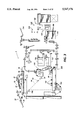
- FIG. 3 is an elevational view illustrating the principal mechanical components of the printing system shown in FIG. 1;
- FIG. 4 is a schematic view showing certain construction details of a document scanner of the printing system shown in FIG. 1;
- FIGS. 5-7 comprise a schematic block diagram showing the major parts of a control section of the printing system shown in FIG. 1;
- FIG. 8 is a block diagram of the Operating System, together with Printed Wiring Boards-and-shared line connections for the printing system shown in FIG. 1;
- FIG. 9 is an elevational view depicting an exemplary job programming ticket and job scorecard displayed on the User Interface(UI) touchscreen of the printing system shown in FIG. 1;
- FIG. 10 is a schematic view depicting a Job File and Print Queue
- FIG. 11 is an elevational view of the User Interface touchscreen display depicting a queue of typical Job Files for jobs in the system
- FIG. 12 is an elevational view of the User Interface touchscreen display depicting a print queue of typical jobs to be printed.
- FIG. 13 is an elevational view of the user interface touch screen display depicting the various finishing options available to an operator.
- FIG. 14 is an expanded, elevational view of the finishing section of the printer shown in FIG. 3;
- FIGS. 15 and 16 comprise a flow diagram depicting various steps of a binding technique embodying the present invention.
- FIG. 17 is a block diagram of a system used to implement the technique depicted in FIGS. 15 and 16;
- FIG. 18 is a schematic representation depicting a manner in which 8 document pages are formed into two 2-up prints
- FIG. 19 is a schematic, elevational view of two 2-up prints folded and stacked in one of the trays of the bindexer of FIG. 17;
- FIG. 20 is a schematic, elevational view of a set of N-up prints bound in conformance with the technique of FIGS. 15 and 16.
- FIGS. 1 and 2 there is shown an exemplary laser-based, printing system 2 for processing printing and finishing jobs in accordance with the teachings of the present invention.
- Printing system 2 for purposes of explanation is divided into a scanner section 6, controller section 7, and printer section 8. While a specific printing system will be shown and described, the present invention may be used with other types of printing systems such as ink jet, ionographic, full frame flash exposure, etc.
- scanner section 6 incorporates a transparent platen 20 on which the document 22 to be scanned is located.
- One or more linear arrays 24 are supported for reciprocating scanning movement below platen 20.
- Lens 26 and mirrors 27, 28, and 29, cooperate to focus on array 24 a line like segment reflected from platen 20 and the document being scanned thereon.
- Array 24 provides image signals or pixels representative of the image scanned which after suitable processing by processor 25, are output to controller section 7.
- Processor 25 converts the analog image signals output by array 24 to digital signals and processes the image signals as required to enable system 2 to store and handle the image data in the form required to carry out the job programmed. Processor 25 also provides enhancements and changes to the image signals such as filtering, thresholding, screening, cropping, reduction/enlarging, etc. Following any changes and adjustments in the job program, the document must be rescanned.
- Documents 22 to be scanned may be located on platen 20 for scanning by automatic document handler (ADF) 35 operable in either a Recirculating Document Handling (RDH) mode or a Semi-Automatic Document Handling (SADH) mode.
- a manual mode including a Book mode and a Computer Forms Feeder (CFF) mode are also provided, the latter to accommodate documents in the form of computer fanfold.
- document handler 35 has a document tray 37 in which documents 22 are arranged in stacks or batches. The documents 22 in tray 37 are advanced by vacuum feed belt 40 and document feed rolls 41 and document feed belt 42 onto platen 20 where the document is scanned by array 24. Following scanning, the document is removed from platen 20 by belt 42 and returned to tray 37 by document feed rolls 44.
- a document entry slot 46 provides access to the document feed belt 42 between tray 37 and platen 20 through which individual documents may be inserted manually for transport to platen 20. Feed rolls 49 behind slot 46 form a nip for engaging and feeding the document to feed belt 42 and onto platen 20. Following scanning, the document is removed from platen 20 and discharged into catch tray 48.
- computer forms material is fed through slot 46 and advanced by feed rolls 49 to document feed belt 42 which in turn advances a page of the fanfold material into position on platen 20.
- printer section 8 comprises a laser type printer and for purposes of explanation is separated into a Raster Output Scanner (ROS) section 87, Print Module Section 95, Paper Supply section 107, and Finisher 120.
- ROS 87 has a laser 90, the beam of which is split into two imaging beams 94.
- Each beam 94 is modulated in accordance with the content of an image signal input by acousto-optic modulator 92 to provide dual imaging beams 94.
- Beams 94 are scanned across a moving photoreceptor 98 of Print Module 95 by the mirrored facets of a rotating polygon 100 to expose two image lines on photoreceptor 98 with each scan and create the latent electrostatic images represented by the image signal input to modulator 92.
- Photoreceptor 98 is uniformly charged by corotrons 102 at a charging station preparatory to exposure by imaging beams 94.
- the latent electrostatic images are developed by developer 104 and transferred at transfer station 106 to a print media 108 delivered by Paper Supply section 107.
- Media 108 may comprise any of a variety of sheet sizes, types, and colors.
- the print media is brought forward in timed registration with the developed image on photoreceptor 98 from either a main paper tray 110 or from auxiliary paper trays 112, or 114.
- the developed image transferred to the print media 108 is permanently fixed or fused by fuser 116 and the resulting prints discharged to either output tray 118, or to output collating trays 119A, B, C in finisher 120.
- Finisher 120 includes a stitcher 122 for stitching (stapling) the prints together to form books, a thermal binder 124 for adhesively binding the prints into books and a stacker 125.
- a finisher of this type is disclosed in U.S. Pat. Nos. 4,828,645 and 4,782,363 whose contents are hereby incorporated by reference.
- controller section 7 is, for explanation purposes, divided into an image input controller 50, User Interface (UI) 52, system controller 54, main memory 56, image manipulation section 58, and image output controller 60.
- UI User Interface
- the scanned image data input from processor 25 of scanner section 6 to controller section 7 is compressed by image compressor/processor 51 of image input controller 50 on PWB 70-3. As the image data passes through compressor/processor 51, it is segmented into slices N scan lines wide, each slice having a slice pointer.
- the compressed image data together with slice pointers and any related image descriptors providing image specific information are placed in an image file.
- the image files, which represent different print jobs, are temporarily stored in system memory 61 which comprises a Random Access Memory or RAM pending transfer to main memory 56 where the data is held pending use.
- UI 52 includes a combined operator controller/CRT display consisting of an interactive touchscreen 62, keyboard 64, and mouse 66.
- UI 52 interfaces the operator with printing system 2, enabling the operator to program print jobs and other instructions, to obtain system operating information, instructions, programming information, diagnostic information, etc.
- Items displayed on touchscreen 62 such as files and icons are actuated by either touching the displayed item on screen 62 with a finger or by using mouse 66 to point cursor 67 to the item selected and keying the mouse.
- Main memory 56 has plural hard disks 90-1, 90-2, 90-3 for storing machine Operating System software, machine operating data, and the scanned image data currently being processed.
- main memory 56 When the compressed image data in main memory 56 requires further processing, or is required for display on touchscreen 62 of UI 52, or is required by printer section 8, the data is accessed in main memory 56. Where further processing other than that provided by processor 25 is required, the data is transferred to image manipulation section 58 on PWB 70-6 where the additional processing steps such as collation, make ready, decomposition, etc are carried out. Following processing, the data may be returned to main memory 56, sent to UI 52 for display on touchscreen 62, or sent to image output controller 60.
- Image data output to image output controller 60 is decompressed and readied for printing by image generating processors 86 of PWBs 70-7, 70-8 (seen in FIG. 5). Following this, the data is output by dispatch processors 88, 89 on PWB 70-9 to printer section 8. Image data sent to printer section 8 for printing is normally purged from memory 56 to make room for new image data.
- control section 7 includes a plurality of Printed Wiring Boards (PWBs) 70, PWBs 70 being coupled with one another and with System Memory 61 by a pair of memory buses 72, 74.
- Memory controller 76 couples System Memory 61 with buses 72, 74.
- PWBs 70 include system processor PWB 70-1 having plural system processors 78; low speed I/O processor PWB 70-2 having UI communication controller 80 for transmitting data to and from UI 52; PWBs 70-3, 70-4, 70-5 having disk drive controller/processors 82 for transmitting data to and from disks 90-1, 90-2, 90-3 respectively of main memory 56 (image compressor/processor 51 for compressing the image data is on PWB 70-3); image manipulation PWB 70-6 with image manipulation processors of image manipulation section 58; image generation processor PWBs 70-7, 70-8 with image generation processors 86 for processing the image data for printing by printer section 8; dispatch processor PWB 70-9 having dispatch processors 88, 89 for controlling transmission of data to and from printer section 8; and boot control-arbitration-scheduler PWB 70-10.
- system processor PWB 70-1 having plural system processors 78
- low speed I/O processor PWB 70-2 having UI communication controller 80 for transmitting data to and from UI
- system control signals are distributed via a plurality of printed wiring boards (PWBs). These include EDN core PWB 130, Marking Imaging core PWB 132, Paper Handling core PWB 134, and Finisher Binder core PWB 136 together with various Input/Output (I/O) PWBs 138.
- a system bus 140 couples the core PWBs 130, 132, 134, 136 with each other and with controller section 7 while local buses 142 serve to couple the I/O PWBs 138 with each other and with their associated core PWB.
- the Operating System software is loaded from memory 56 to EDN core PWB 130 and from there to the remaining core PWBs 132, 134, 136 via bus 140, each core PWB 130, 132, 134, 136 having a boot ROM 147 for controlling down-loading of Operating System software to the PWB, fault detection, etc.
- Boot ROMs 147 also enable transmission of Operating System software and control data to and from PWBs 130, 132, 134, 136 via bus 140 and control data to and from I/O PWBs 138 via local buses 142. Additional ROM, RAM, and NVM memory types are resident at various locations within system 2.
- jobs are programmed in a Job Program mode in which there is displayed on touchscreen 62 a Job Ticket 150 and a Job Scorecard 152 for the job being programmed.
- Job Ticket 150 displays various job selections programmed, while Job Scorecard 152 displays the basic instructions to the system for printing the job.
- the image files are arranged in a job file 155, with the print jobs 156 numbered consecutively in the order in which the print jobs are scanned in.
- a SYSTEM FILE icon 157 (FIG. 9) on touchscreen 62 is actuated.
- This displays an image queue 160 of the jobs 156 currently in the job file on screen 62, an example of which is shown in FIG. 11.
- Each job is identified by a descriptor showing the type of job, job number, number of prints, etc.
- up and down scrolling icons 161, 162 the operator can scroll the list of jobs where the number of jobs in the job file is too large to be simultaneously displayed on touchscreen 62.
- a PRINTER QUEUE icon 167 on touchscreen 62 when actuated, displays the current print queue with a list of the jobs in the queue on touchscreen 62, an example of which is shown in FIG. 12.
- Each job in print queue 165 has a job descriptor identifying the job, job number, quantity to be printed, paper color, finishing type, etc.
- Print queue 165 is ordered by priority and time of arrival of the job in the print queue. Other priority orderings may be envisioned.
- the image queue 160 is displayed (if not already displayed on screen 62) and the particular job identified.
- the parts of the jobs image file required for the processing selected are accessed, the image data decompressed and converted to the resolution required for display on screen 62.
- the image data is compressed and returned to main memory 56.
- a job 156 in print queue 165 may be removed from queue 165 any time before printing has commenced and returned to the job file 155. In that case, the image file removed loses its position in the print queue.
- the image file having compressed image data, image slice pointers, and descriptors of the job is read from disks 90-1, 90-2, 90-3 of main memory 56 into system memory 61.
- the image data is formatted and processed in blocks called bands.
- Band descriptors which provide descriptions of the objects within a page, base addresses for all of the scan lines in the band, the start addresses for each band, and the starting position for each page, are created.
- packets of information referred to as image parameter blocks containing all the information needed for the image generation processors 86 (seen in FIG. 5) to retrieve the image data for processing and printing, are created.
- Processors 86 include a decoder, depredictor, and image generating logic to in effect decompress the image data and provide the binary image data used by printer section 8 to make prints.
- the image file for the job is normally purged from memory 56 to make room for new job.
- FIG. 13 shows the touch screen 62 display and FIG. 14 shows further details of the stitcher 122 and binder 124.
- jobs requiring a finishing activity are programmed in a job program mode in which there is displayed on touch screen 62 a series of icons enabling selection of various finishing options.
- a binding icon 194-1 is selected for jobs to be bound and 3 stitching options are enabled by icon 194-2 (single stitch), 194-3 (dual stitch) and 194-4 (landscape). These selections enable the particular operation to be accomplished in the finisher section 120.
- FIG. 14 shows a more detailed view of the finisher section 120.
- a pair of set clamps 200, 202 are mounted on a set transport charge 204 and pneumatically driven by a compressor. If a binding operation is selected (194-2), set clamp 200 removes printed sets from bin 119 and delivers to a tilt bed in binder 124 which is adapted to receive a set of copy sheets from clamp 200 and position the set of copy sheets for the binding operation.
- Thermal binding requires time to melt the binding adhesive and time to permit the bound set (book) to cool prior to further handling. These operations consume between 27 and 125 pitches-typically one pitch for each sheet in the set.
- the bound sheets are raised for pickup by set clamp 202 which delivers them to stacker 125. Further details of the operation of the binder 124 are to found in U.S. Pat. No. 4,828,645 and U.S. Pat. No. 5,095,369, the pertinent portions of the '369 patent being incorporated herein by reference.
- a pseudo-signature in one example, is a 2-up print, i.e. a duplex printed copy sheet having two page images on each side.
- a pseudo-signature can be folded in half to form a pamphlet, or a plurality of individually folded pseudo-signatures can, as discussed in further detail below, be bound together to form a multi- sheet booklet. It will be appreciated that the technique of the disclosed embodiment could be implemented with N-up prints other than 2-up prints without altering the concept upon which such embodiment is based.
- a user of the printing machine 10 programs the finishing options for a given job, the given job corresponding with a plurality of electronic pages stored in memory 56 or 61 (FIGS. 2 or 5-7).
- the "given job” will be referenced below whenever appropriate.
- an option referred to as "enhanced binding” appears, provided the number of electronic pages associated with the given job is less than a preselected number. If the printing system user desires enhanced binding, the significance of which will appear, then the enhanced binding option is selected by way of a fingertip or a pointer 67.
- thermal adhesive binding varies as a function of various factors. Two of such factors include stock characteristics and number of prints to be bound.
- a relatively large booklet e.g. >60 prints for a wide variety of stock types
- the quality of binding is quite high.
- the number of prints that constitute a "relatively large booklet” will vary according to the stock type of the prints to be bound. It has been found that durability of relatively large booklets is quite good. For example, with relatively large booklets pages are not torn out cleanly by way of a "page tear" test.
- step 302 is optimally provided in an automatic mode.
- the number of pages of a given job is inputted to the printing system 10 by way of the dialog of FIG. 9.
- this information which can be obtained by the controller 7 (FIGS. 2 and 5-7) at a later time, is stored in memory.
- the controller determines whether the given job, due to its associated size is an eligible candidate for the below-described enhanced printing. If the given job is above a given page threshold, which threshold is settable by a printing system operator, then the routine of FIG. 5 exits, by way of a return, so that normal programming for thermal adhesive binding can be followed. If enhanced binding is offered and requested, however, a variety of suitable programming defaults are stored in memory (step 304). The particulars of these suitable programming defaults will appear from the discussion below.
- the controller in facilitating execution of the job, refers to the various stored programming defaults.
- FIG. 17 the structural components employed in implementing the enhanced binding process are shown.
- the structural components include the printing machine of FIGS. 1 and 2 (i.e., the printing machine including subsytems 6-8), a folding device 308 (of the type disclosed above), a bindexing arrangement 310 (i.e., a stacking arrangement of the type shown in FIG. 3) and a binder 312 (of the type shown in FIG. 14).
- the controller 7 enables the folding apparatus (step 316) and assigns one of the trays 110, 112 or 114 (FIG. 3) (step 318) for the given job.
- a selected substrate size e.g., 11 ⁇ 17 paper
- this programming can be provided in the form of automatic or manual programming. If the paper size in the assigned tray corresponds with the paper programmed for the given job (check performed at step 320) then the process proceeds to step 321, otherwise operation is inhibited, by way of loop including step 322, until the operator loads the substrate trays with the properly sized substrates.
- pseudo-signature utility for suitable electronic ordering of the electronic pages into pseudo-signatures (step 324).
- the pseudo-signature utility of the presently disclosed embodiment uses software similar to that used in the DocuTech® printing system except that the software of the present embodiment is modified to electronically order sheets in such a manner that the second set of four pages follows the first set of four pages, the third set of four pages follows the second set of four pages, and so on.
- the concept of the code, upon which the present pseudo-signature utility is based, is discussed further in U.S. Pat. No. 5,271,065.
- the ordering approach of the present software is illustrated, in further detail, by way of example.
- the first four pages are ordered into a first pseudo-signature while the second four pages are ordered into a second pseudo-signature.
- This is in contrast to "true" signaturization, as performed in the DocuTech® printing system, where pages 1, 2, 7 and 8 would be ordered on the first signature and pages 3-6 would be ordered on the second signature.
- true signaturization as performed in the DocuTech® printing system, where pages 1, 2, 7 and 8 would be ordered on the first signature and pages 3-6 would be ordered on the second signature.
- the principles required to perform true signaturization are applicable directly to the implementation of the pseudo-signature utility of the present embodiment. Since, as shown in FIG. 18, four electronic pages are arranged on each pseudo-signature and the number of electronic pages for the job may not be a multiple of four, in some cases the last pseudo-signature of a given job may include up to three blank sides.
- the M pseudo-signatures are marked in accordance with the marking technique of the DocuTech® printing system.
- various image-related components of the given job are retrieved (step 326), by reference to a database, in what is referred to as a post-parsing operation.
- the electronic pages of the given job are streamed through the pseudo-signaturizing software and the postparsing software so as to place the given job in a format suitable for consumption by marking software.
- a sheet counter referencing a list of the electronic pages for the given job is set at the first electronic page of the job (step 330) and a variable J, the significance of which will appear below, is set, at step 332, to a value of one.
- Imaging also referred to herein as "marking”
- the sheet counter is incremented to the next electronic page (step 336).
- a check is then performed at step 338 to determine if the referenced electronic page is either the fourth page in a pseudo-signature or the last page of the given job. If the printer is not finished marking the current pseudo-signature, then the process loops back to step 334 until marking of the current pseudo-signature is completed.
- the current pseudo-signature When the current pseudo-signature is marked, it is, by way of step 342, transported to the folding device 308.
- the current pseudo-signature is then folded (step 344) and then, via step 346, transported to one of the trays in the bindexer 310 (FIGS. 17 and 19). If any existing pseudo-signatures are present in the bindexer tray, the current, individually folded pseudo-signature is stacked on top of the existing pseudo-signatures.
- the registration step 348 is performed when multiple pseudo-signatures are present in the bindexer tray. Referring to FIG. 19, two pseudo-signatures, generated in accordance with the present technique are shown folded and stacked in the bindexer tray. It will be recognized that the registered, folded pseudo-signatures are disposed in such a manner that they can be delivered directly to the binder of FIG. 14 for binding.
- step 348 the sheet counter is checked (step 350) to determine if it is currently referenced to an electronic page exceeding the last electronic page of the given job. If further pages require marking, the variable J is incremented (step 352) and the process loops back to step 334.
- the set is, via step 354, transferred to the thermal adhesive binding apparatus of FIG. 14 where adhesive is applied to each of the folded edges of the set of individually folded pseudo-signatures (step 356) in accordance with the above described thermal binding process.
- all of the folded edges of the set 360 are disposed along a common axis and in contact with adhesive 362. It is contemplated that binding processes other than thermal binding could be used to achieve the present enhanced binding technique, provided an adhesive layer is applied to the folded edges of registered, folded pseudo-signatures.
- Much of the paper used to form books is composed of fibrous and sizing materials, the sizing materials including materials that are well known in the paper-producing arts. Paper formed with sizing materials will be referred to herein as "treated paper".
- a binding for a relatively small book in which an adhesive contacts a treated paper edge has been found to be less than desirable since the bond between each treated edge and the adhesive tends to be relatively weak. Indeed, it has been found that for relatively small books in which treated edges are bound with adhesive, the associated pages can be torn out rather easily.
- each sheet is folded in such a manner that the sheet is creased so that the sizing materials of the sheet are "cracked” and fibers are exposed. This cracking of the sizing materials creates better fiber exposure at each folded edge. Accordingly, as the adhesive is applied to each folded edge, the adhesive intrudes the structure of each folded page. For each folded page, this permits a bond between the adhesive and the fibers of the sheet, which bond has been found to be far superior to a bond between an adhesive and a treated paper edge
- the booklet bound in accordance with the enhanced binding process of FIGS. 15 and 16 is believed to particularly durable, relative to other relatively small booklets bound with regular substrates, for various reasons.
- Second, the surface area of each folded edge is substantially greater than the edge of a single substrate. Therefore, the adhesive contact for the various edges is greater than it would be if only single sheet edges were contacted by the adhesive.
- the folding and creasing action for each pseudo-signature causes the sizing or surface finish on the corresponding sheet to become exposed, allowing improved adhesive grip on the structure of the sheets. Such exposure is particularly beneficial in permitting the binding of coated papers.
- N-up prints are generated with a printing machine, from ordered electronic pages of a job, and delivered, one at a time, to a folding device.
- the folding device folds each of the N-up prints, individually, and passes them along to a stacking area where the individually folded N-up prints are stacked in registered form.
- the set is delivered to an adhesive binding device where the N-up prints are bound securely with one another.
- the binding system decides automatically whether to provide a printing system user with the opportunity to use the enhanced binding process, for a given job, in a manner that is transparent to the user. That is, the printing system decides, based on the number of electronic pages corresponding to the job, whether to permit use of the enhanced binding mode. Preferably, the number can be adjusted readily by a printing machine operator.
- the user is provided with expert guidance as to which type of thermal adhesive binding should be employed. Such guidance is believed necessary in that using folded sheets to create a relatively large booklet could result in an asymmetrical booklet where the bound side is considerably fatter than the unbound side.
Abstract
Description
Claims (10)
Priority Applications (1)
| Application Number | Priority Date | Filing Date | Title |
|---|---|---|---|
| US08/356,614 US5547176A (en) | 1994-12-15 | 1994-12-15 | Apparatus and method for binding pseudo-signatures into a booklet |
Applications Claiming Priority (1)
| Application Number | Priority Date | Filing Date | Title |
|---|---|---|---|
| US08/356,614 US5547176A (en) | 1994-12-15 | 1994-12-15 | Apparatus and method for binding pseudo-signatures into a booklet |
Publications (1)
| Publication Number | Publication Date |
|---|---|
| US5547176A true US5547176A (en) | 1996-08-20 |
Family
ID=23402201
Family Applications (1)
| Application Number | Title | Priority Date | Filing Date |
|---|---|---|---|
| US08/356,614 Expired - Lifetime US5547176A (en) | 1994-12-15 | 1994-12-15 | Apparatus and method for binding pseudo-signatures into a booklet |
Country Status (1)
| Country | Link |
|---|---|
| US (1) | US5547176A (en) |
Cited By (15)
| Publication number | Priority date | Publication date | Assignee | Title |
|---|---|---|---|---|
| US6213703B1 (en) | 1996-10-04 | 2001-04-10 | Instabook Corporation | Electronic bookstore vending machine |
| US20020061238A1 (en) * | 1999-04-29 | 2002-05-23 | Marsh Jeffrey D. | Apparatus and method of on demand printing, binding, and trimming a perfect bound book |
| US20020064436A1 (en) * | 1999-04-29 | 2002-05-30 | Marsh Jeffrey D. | Perfect bound book having a double laminated cover and method of and apparatus for manufacturing same |
| EP1234685A2 (en) | 2001-02-22 | 2002-08-28 | Heidelberger Druckmaschinen Aktiengesellschaft | Binding element and device for digital printing |
| WO2003009065A1 (en) * | 2001-07-19 | 2003-01-30 | Krdc Co., Ltd. | Paper binding system of image forming apparatus and method for controlling the same |
| US20030099526A1 (en) * | 2001-11-26 | 2003-05-29 | Saw Chit Wei | Cover authoring systems and methods and bookbinding systems incorporating the same |
| US20040028505A1 (en) * | 2002-06-07 | 2004-02-12 | Bilbrey Robert A. | Document tape binding system with automatic tape feed, tape indicia sensing, spine printing method and post-bind automation mechanisms |
| US20040220035A1 (en) * | 2003-04-30 | 2004-11-04 | Villanueva Jose Alvaro Barba | Apparatus and method for creasing media to make booklets |
| US6817605B1 (en) | 2003-04-30 | 2004-11-16 | Hewlett-Packard Development Company, L.P. | Method and apparatus for creating a pillowless booklet |
| US6827346B2 (en) | 2003-04-30 | 2004-12-07 | Hewlett-Packard Development Company, L.P. | Method and apparatus for making booklets |
| US20080013973A1 (en) * | 2001-06-25 | 2008-01-17 | Canon Kabushiki Kaisha | Image Forming Apparatus and Image Forming Method |
| US7509671B1 (en) * | 2001-06-20 | 2009-03-24 | Microstrategy Incorporated | Systems and methods for assigning priority to jobs in a reporting system |
| US20110044786A1 (en) * | 2009-08-18 | 2011-02-24 | Perfect Systems, Llc | Apparatus for and method of clamping and trimming a perfect bound book |
| US7963733B2 (en) | 2008-10-01 | 2011-06-21 | Perfect Systems, Llc | Apparatus for and a method of binding of a perfect bound book |
| US20110159170A1 (en) * | 2009-12-17 | 2011-06-30 | Marsh Jeffrey D | Apparatus for and a method of determining condition of hot melt adhesive for binding of a perfect bound book |
Citations (23)
| Publication number | Priority date | Publication date | Assignee | Title |
|---|---|---|---|---|
| US1988208A (en) * | 1934-04-16 | 1935-01-15 | Martin Machinery Corp | Bookbinding machine and method |
| US2185721A (en) * | 1938-04-25 | 1940-01-02 | Carbon Systems Inc | Manifold unit and method of producing the same |
| US3093396A (en) * | 1960-12-22 | 1963-06-11 | Betsy Ross Feld | Bookbinding method and apparatus |
| US4129471A (en) * | 1975-06-05 | 1978-12-12 | Rome Industries, Inc. | Bookbinding technique |
| GB2025328A (en) * | 1978-07-06 | 1980-01-23 | Mitsui Zellerbach Kk | Method of Folding Synthetic Pulp Paper |
| US4194832A (en) * | 1977-12-30 | 1980-03-25 | Toppan Printing Co., Ltd. | Consecutive copying and bookbinding method and its apparatus |
| US4406649A (en) * | 1980-10-01 | 1983-09-27 | Fuji Xerox Co., Ltd. | Sheet folding machine used with copying machine |
| US4518381A (en) * | 1980-10-01 | 1985-05-21 | Fuji Xerox Co., Ltd. | Sheet folding machine |
| US4525116A (en) * | 1982-12-27 | 1985-06-25 | The Holmberg Company | Prefabricated bindable sheet and binding method and apparatus |
| US4643705A (en) * | 1985-07-29 | 1987-02-17 | Xerox Corporation | Positive drive knife folder |
| US4727402A (en) * | 1986-12-18 | 1988-02-23 | Xerox Corporation | Automatic copier signature set production |
| US4782363A (en) * | 1987-09-17 | 1988-11-01 | Xerox Corporation | Copying system for on-line finishing |
| US4797048A (en) * | 1987-09-08 | 1989-01-10 | Xerox Corporation | Binding apparatus |
| US4828645A (en) * | 1987-11-25 | 1989-05-09 | Xerox Corporation | Binding apparatus |
| US4828636A (en) * | 1986-08-29 | 1989-05-09 | Svecia Antiqua S.A. | Method for producing multi-page documents from a material web |
| US4869712A (en) * | 1987-03-31 | 1989-09-26 | Fuji Xerox Co., Ltd. | Paper folding apparatus |
| US4958974A (en) * | 1989-08-07 | 1990-09-25 | Xerox Corporation | Damped binding apparatus |
| US4975011A (en) * | 1989-09-27 | 1990-12-04 | Holmberg Albert E | Solvent activated bindable sheet and method and apparatus for producing bound booklets |
| US5011187A (en) * | 1988-01-14 | 1991-04-30 | Minnesota Mining And Manufacturing Company | Binding system for connected fan folded sheets |
| US5174556A (en) * | 1991-11-20 | 1992-12-29 | Xerox Corporation | Finisher with binder printing |
| US5184185A (en) * | 1991-08-29 | 1993-02-02 | Xerox Corporation | Method for duplex printing scheduling system combining finisher interset skipped pitches with duplex sheet scheduling |
| US5221112A (en) * | 1991-12-11 | 1993-06-22 | Holmberg Albert E | Method and apparatus for binding books |
| US5271065A (en) * | 1990-09-28 | 1993-12-14 | Xerox Corporation | Electronic printing system for printing signatures |
-
1994
- 1994-12-15 US US08/356,614 patent/US5547176A/en not_active Expired - Lifetime
Patent Citations (23)
| Publication number | Priority date | Publication date | Assignee | Title |
|---|---|---|---|---|
| US1988208A (en) * | 1934-04-16 | 1935-01-15 | Martin Machinery Corp | Bookbinding machine and method |
| US2185721A (en) * | 1938-04-25 | 1940-01-02 | Carbon Systems Inc | Manifold unit and method of producing the same |
| US3093396A (en) * | 1960-12-22 | 1963-06-11 | Betsy Ross Feld | Bookbinding method and apparatus |
| US4129471A (en) * | 1975-06-05 | 1978-12-12 | Rome Industries, Inc. | Bookbinding technique |
| US4194832A (en) * | 1977-12-30 | 1980-03-25 | Toppan Printing Co., Ltd. | Consecutive copying and bookbinding method and its apparatus |
| GB2025328A (en) * | 1978-07-06 | 1980-01-23 | Mitsui Zellerbach Kk | Method of Folding Synthetic Pulp Paper |
| US4406649A (en) * | 1980-10-01 | 1983-09-27 | Fuji Xerox Co., Ltd. | Sheet folding machine used with copying machine |
| US4518381A (en) * | 1980-10-01 | 1985-05-21 | Fuji Xerox Co., Ltd. | Sheet folding machine |
| US4525116A (en) * | 1982-12-27 | 1985-06-25 | The Holmberg Company | Prefabricated bindable sheet and binding method and apparatus |
| US4643705A (en) * | 1985-07-29 | 1987-02-17 | Xerox Corporation | Positive drive knife folder |
| US4828636A (en) * | 1986-08-29 | 1989-05-09 | Svecia Antiqua S.A. | Method for producing multi-page documents from a material web |
| US4727402A (en) * | 1986-12-18 | 1988-02-23 | Xerox Corporation | Automatic copier signature set production |
| US4869712A (en) * | 1987-03-31 | 1989-09-26 | Fuji Xerox Co., Ltd. | Paper folding apparatus |
| US4797048A (en) * | 1987-09-08 | 1989-01-10 | Xerox Corporation | Binding apparatus |
| US4782363A (en) * | 1987-09-17 | 1988-11-01 | Xerox Corporation | Copying system for on-line finishing |
| US4828645A (en) * | 1987-11-25 | 1989-05-09 | Xerox Corporation | Binding apparatus |
| US5011187A (en) * | 1988-01-14 | 1991-04-30 | Minnesota Mining And Manufacturing Company | Binding system for connected fan folded sheets |
| US4958974A (en) * | 1989-08-07 | 1990-09-25 | Xerox Corporation | Damped binding apparatus |
| US4975011A (en) * | 1989-09-27 | 1990-12-04 | Holmberg Albert E | Solvent activated bindable sheet and method and apparatus for producing bound booklets |
| US5271065A (en) * | 1990-09-28 | 1993-12-14 | Xerox Corporation | Electronic printing system for printing signatures |
| US5184185A (en) * | 1991-08-29 | 1993-02-02 | Xerox Corporation | Method for duplex printing scheduling system combining finisher interset skipped pitches with duplex sheet scheduling |
| US5174556A (en) * | 1991-11-20 | 1992-12-29 | Xerox Corporation | Finisher with binder printing |
| US5221112A (en) * | 1991-12-11 | 1993-06-22 | Holmberg Albert E | Method and apparatus for binding books |
Non-Patent Citations (2)
| Title |
|---|
| Oagley, Jack R., "In-Line Sheet Folder" Xerox Disclosure Journal, vol. 18, No. 1, Jan./Feb. 1993, pp. 113-122. |
| Oagley, Jack R., In Line Sheet Folder Xerox Disclosure Journal, vol. 18, No. 1, Jan./Feb. 1993, pp. 113 122. * |
Cited By (25)
| Publication number | Priority date | Publication date | Assignee | Title |
|---|---|---|---|---|
| US6213703B1 (en) | 1996-10-04 | 2001-04-10 | Instabook Corporation | Electronic bookstore vending machine |
| US20100266368A1 (en) * | 1999-04-29 | 2010-10-21 | Perfect Systems, Llc | Apparatus and method of on demand printing, binding, and trimming a perfect bound book |
| US7694947B2 (en) | 1999-04-29 | 2010-04-13 | Perfect Systems, Llc | Apparatus and method of on demand printing, binding, and trimming a perfect bound book |
| US6986630B2 (en) | 1999-04-29 | 2006-01-17 | Marsh Jeffrey D | Perfect bound book having a double laminated cover and method of and apparatus for manufacturing same |
| US20020061238A1 (en) * | 1999-04-29 | 2002-05-23 | Marsh Jeffrey D. | Apparatus and method of on demand printing, binding, and trimming a perfect bound book |
| US20020064436A1 (en) * | 1999-04-29 | 2002-05-30 | Marsh Jeffrey D. | Perfect bound book having a double laminated cover and method of and apparatus for manufacturing same |
| US7014182B2 (en) | 1999-04-29 | 2006-03-21 | Marsh Jeffrey D | Apparatus and method of on demand printing, binding, and trimming a perfect bound book |
| US20060140743A1 (en) * | 1999-04-29 | 2006-06-29 | Marsh Jeffrey D | Apparatus and method of on demand printing, binding, and trimming a perfect bound book |
| US8177212B2 (en) | 1999-04-29 | 2012-05-15 | Perfect Systems, Llc | Apparatus and method of on demand printing, binding, and trimming a perfect bound book |
| EP1234685A2 (en) | 2001-02-22 | 2002-08-28 | Heidelberger Druckmaschinen Aktiengesellschaft | Binding element and device for digital printing |
| US7509671B1 (en) * | 2001-06-20 | 2009-03-24 | Microstrategy Incorporated | Systems and methods for assigning priority to jobs in a reporting system |
| US20080013973A1 (en) * | 2001-06-25 | 2008-01-17 | Canon Kabushiki Kaisha | Image Forming Apparatus and Image Forming Method |
| US8259340B2 (en) * | 2001-06-25 | 2012-09-04 | Canon Kabushiki Kaisha | Image forming apparatus and image forming method |
| WO2003009065A1 (en) * | 2001-07-19 | 2003-01-30 | Krdc Co., Ltd. | Paper binding system of image forming apparatus and method for controlling the same |
| US6910843B2 (en) * | 2001-11-26 | 2005-06-28 | Hewlett-Packard Development Company, L.P. | Cover authoring systems and methods and bookbinding systems incorporating the same |
| US20030099526A1 (en) * | 2001-11-26 | 2003-05-29 | Saw Chit Wei | Cover authoring systems and methods and bookbinding systems incorporating the same |
| US20040028505A1 (en) * | 2002-06-07 | 2004-02-12 | Bilbrey Robert A. | Document tape binding system with automatic tape feed, tape indicia sensing, spine printing method and post-bind automation mechanisms |
| US6817605B1 (en) | 2003-04-30 | 2004-11-16 | Hewlett-Packard Development Company, L.P. | Method and apparatus for creating a pillowless booklet |
| US6827679B2 (en) | 2003-04-30 | 2004-12-07 | Hewlett-Packard Development Company, L.P. | Apparatus and method for creasing media to make booklets |
| US6827346B2 (en) | 2003-04-30 | 2004-12-07 | Hewlett-Packard Development Company, L.P. | Method and apparatus for making booklets |
| US20040220035A1 (en) * | 2003-04-30 | 2004-11-04 | Villanueva Jose Alvaro Barba | Apparatus and method for creasing media to make booklets |
| US7963733B2 (en) | 2008-10-01 | 2011-06-21 | Perfect Systems, Llc | Apparatus for and a method of binding of a perfect bound book |
| US20110044786A1 (en) * | 2009-08-18 | 2011-02-24 | Perfect Systems, Llc | Apparatus for and method of clamping and trimming a perfect bound book |
| US20110159170A1 (en) * | 2009-12-17 | 2011-06-30 | Marsh Jeffrey D | Apparatus for and a method of determining condition of hot melt adhesive for binding of a perfect bound book |
| US8739730B2 (en) | 2009-12-17 | 2014-06-03 | Jeffrey D. Marsh | Apparatus for and a method of determining condition of hot melt adhesive for binding of a perfect bound book |
Similar Documents
| Publication | Publication Date | Title |
|---|---|---|
| US5547176A (en) | Apparatus and method for binding pseudo-signatures into a booklet | |
| US5159395A (en) | Method of scheduling copy sheets in a dual mode duplex printing system | |
| JP3181078B2 (en) | Method and apparatus for causing a finishing machine to form an optimum overlap state for each print set, an electronic copying apparatus using the same, and a method for forming an optimum overlap state for each print set in an electronic printer | |
| EP0477569B1 (en) | Electronic printing system for printing signatures | |
| US5489969A (en) | Apparatus and method of controlling interposition of sheet in a stream of imaged substrates | |
| US5206735A (en) | Job interrupt for electronic copying/printing machines | |
| JP2523235B2 (en) | How to operate an electronic copier to make a proof | |
| JP3449568B2 (en) | Electronic image processing apparatus and its operation method | |
| US5596389A (en) | Apparatus and method for scheduling an imagable substrate and a special sheet to be fed in the same pitch | |
| EP1813437B1 (en) | Bookbinding device, bookbinding method, and printing device | |
| US5124731A (en) | Generation of document covers in an electronic reprographic system using memory | |
| US5107299A (en) | Printer job recovery of complete or partially complete jobs in an electronic reprographic printing system | |
| US5697040A (en) | Print job intermixing within marking machine | |
| US5179410A (en) | Printer dynamic job recovery in an electronic reprographic printing system | |
| US5210622A (en) | Automatic variable image shift for precut tabs | |
| US5450541A (en) | Method of applying electronically stored labels to a print job | |
| JPH04313951A (en) | Apparatus for scanning document of section | |
| US5452068A (en) | Apparatus and method for reducing productivity losses in a marking engine | |
| JPH04330851A (en) | Job addition method for electronic printer | |
| US5107339A (en) | Method and apparatus for stream printing in an electronic reprographic device | |
| JPH04252333A (en) | Method for establishing printing sequence | |
| EP0488814B1 (en) | System for scanning signature pages | |
| JPH04230516A (en) | Address specifying method for electronic printer | |
| EP0478351A2 (en) | Page number generation and formatting in electronic reprographic/printing products | |
| US5559595A (en) | Apparatus and method for scheduling inversions of post printing inserts |
Legal Events
| Date | Code | Title | Description |
|---|---|---|---|
| AS | Assignment |
Owner name: XEROX CORPORATION, CONNECTICUT Free format text: ASSIGNMENT OF ASSIGNORS INTEREST;ASSIGNORS:WILLIAMS, GEOFFREY C.;VANBORTEL, DAVID P.;REEL/FRAME:007263/0995 Effective date: 19941212 |
|
| STCF | Information on status: patent grant |
Free format text: PATENTED CASE |
|
| FPAY | Fee payment |
Year of fee payment: 4 |
|
| AS | Assignment |
Owner name: BANK ONE, NA, AS ADMINISTRATIVE AGENT, ILLINOIS Free format text: SECURITY INTEREST;ASSIGNOR:XEROX CORPORATION;REEL/FRAME:013153/0001 Effective date: 20020621 |
|
| AS | Assignment |
Owner name: JPMORGAN CHASE BANK, AS COLLATERAL AGENT, TEXAS Free format text: SECURITY AGREEMENT;ASSIGNOR:XEROX CORPORATION;REEL/FRAME:015134/0476 Effective date: 20030625 Owner name: JPMORGAN CHASE BANK, AS COLLATERAL AGENT,TEXAS Free format text: SECURITY AGREEMENT;ASSIGNOR:XEROX CORPORATION;REEL/FRAME:015134/0476 Effective date: 20030625 |
|
| FPAY | Fee payment |
Year of fee payment: 8 |
|
| REMI | Maintenance fee reminder mailed | ||
| FPAY | Fee payment |
Year of fee payment: 12 |
|
| SULP | Surcharge for late payment |
Year of fee payment: 11 |
|
| AS | Assignment |
Owner name: XEROX CORPORATION, CONNECTICUT Free format text: RELEASE BY SECURED PARTY;ASSIGNOR:JPMORGAN CHASE BANK, N.A. AS SUCCESSOR-IN-INTEREST ADMINISTRATIVE AGENT AND COLLATERAL AGENT TO JPMORGAN CHASE BANK;REEL/FRAME:066728/0193 Effective date: 20220822 |