US5539977A - Apparatus and method for automatically mounting electronic parts - Google Patents
Apparatus and method for automatically mounting electronic parts Download PDFInfo
- Publication number
- US5539977A US5539977A US08/330,749 US33074994A US5539977A US 5539977 A US5539977 A US 5539977A US 33074994 A US33074994 A US 33074994A US 5539977 A US5539977 A US 5539977A
- Authority
- US
- United States
- Prior art keywords
- end position
- electronic parts
- section
- holding
- parts
- Prior art date
- Legal status (The legal status is an assumption and is not a legal conclusion. Google has not performed a legal analysis and makes no representation as to the accuracy of the status listed.)
- Expired - Lifetime
Links
Images


Classifications
-
- H—ELECTRICITY
- H05—ELECTRIC TECHNIQUES NOT OTHERWISE PROVIDED FOR
- H05K—PRINTED CIRCUITS; CASINGS OR CONSTRUCTIONAL DETAILS OF ELECTRIC APPARATUS; MANUFACTURE OF ASSEMBLAGES OF ELECTRICAL COMPONENTS
- H05K13/00—Apparatus or processes specially adapted for manufacturing or adjusting assemblages of electric components
- H05K13/04—Mounting of components, e.g. of leadless components
- H05K13/0404—Pick-and-place heads or apparatus, e.g. with jaws
- H05K13/0408—Incorporating a pick-up tool
- H05K13/041—Incorporating a pick-up tool having multiple pick-up tools
-
- H—ELECTRICITY
- H05—ELECTRIC TECHNIQUES NOT OTHERWISE PROVIDED FOR
- H05K—PRINTED CIRCUITS; CASINGS OR CONSTRUCTIONAL DETAILS OF ELECTRIC APPARATUS; MANUFACTURE OF ASSEMBLAGES OF ELECTRICAL COMPONENTS
- H05K13/00—Apparatus or processes specially adapted for manufacturing or adjusting assemblages of electric components
- H05K13/04—Mounting of components, e.g. of leadless components
-
- H—ELECTRICITY
- H05—ELECTRIC TECHNIQUES NOT OTHERWISE PROVIDED FOR
- H05K—PRINTED CIRCUITS; CASINGS OR CONSTRUCTIONAL DETAILS OF ELECTRIC APPARATUS; MANUFACTURE OF ASSEMBLAGES OF ELECTRICAL COMPONENTS
- H05K13/00—Apparatus or processes specially adapted for manufacturing or adjusting assemblages of electric components
- H05K13/08—Monitoring manufacture of assemblages
- H05K13/081—Integration of optical monitoring devices in assembly lines; Processes using optical monitoring devices specially adapted for controlling devices or machines in assembly lines
- H05K13/0812—Integration of optical monitoring devices in assembly lines; Processes using optical monitoring devices specially adapted for controlling devices or machines in assembly lines the monitoring devices being integrated in the mounting machine, e.g. for monitoring components, leads, component placement
-
- H—ELECTRICITY
- H05—ELECTRIC TECHNIQUES NOT OTHERWISE PROVIDED FOR
- H05K—PRINTED CIRCUITS; CASINGS OR CONSTRUCTIONAL DETAILS OF ELECTRIC APPARATUS; MANUFACTURE OF ASSEMBLAGES OF ELECTRICAL COMPONENTS
- H05K13/00—Apparatus or processes specially adapted for manufacturing or adjusting assemblages of electric components
- H05K13/08—Monitoring manufacture of assemblages
- H05K13/081—Integration of optical monitoring devices in assembly lines; Processes using optical monitoring devices specially adapted for controlling devices or machines in assembly lines
- H05K13/0813—Controlling of single components prior to mounting, e.g. orientation, component geometry
-
- Y—GENERAL TAGGING OF NEW TECHNOLOGICAL DEVELOPMENTS; GENERAL TAGGING OF CROSS-SECTIONAL TECHNOLOGIES SPANNING OVER SEVERAL SECTIONS OF THE IPC; TECHNICAL SUBJECTS COVERED BY FORMER USPC CROSS-REFERENCE ART COLLECTIONS [XRACs] AND DIGESTS
- Y10—TECHNICAL SUBJECTS COVERED BY FORMER USPC
- Y10T—TECHNICAL SUBJECTS COVERED BY FORMER US CLASSIFICATION
- Y10T29/00—Metal working
- Y10T29/49—Method of mechanical manufacture
- Y10T29/49002—Electrical device making
- Y10T29/49117—Conductor or circuit manufacturing
- Y10T29/49124—On flat or curved insulated base, e.g., printed circuit, etc.
- Y10T29/4913—Assembling to base an electrical component, e.g., capacitor, etc.
- Y10T29/49131—Assembling to base an electrical component, e.g., capacitor, etc. by utilizing optical sighting device
-
- Y—GENERAL TAGGING OF NEW TECHNOLOGICAL DEVELOPMENTS; GENERAL TAGGING OF CROSS-SECTIONAL TECHNOLOGIES SPANNING OVER SEVERAL SECTIONS OF THE IPC; TECHNICAL SUBJECTS COVERED BY FORMER USPC CROSS-REFERENCE ART COLLECTIONS [XRACs] AND DIGESTS
- Y10—TECHNICAL SUBJECTS COVERED BY FORMER USPC
- Y10T—TECHNICAL SUBJECTS COVERED BY FORMER US CLASSIFICATION
- Y10T29/00—Metal working
- Y10T29/49—Method of mechanical manufacture
- Y10T29/49002—Electrical device making
- Y10T29/49117—Conductor or circuit manufacturing
- Y10T29/49124—On flat or curved insulated base, e.g., printed circuit, etc.
- Y10T29/4913—Assembling to base an electrical component, e.g., capacitor, etc.
- Y10T29/49144—Assembling to base an electrical component, e.g., capacitor, etc. by metal fusion
-
- Y—GENERAL TAGGING OF NEW TECHNOLOGICAL DEVELOPMENTS; GENERAL TAGGING OF CROSS-SECTIONAL TECHNOLOGIES SPANNING OVER SEVERAL SECTIONS OF THE IPC; TECHNICAL SUBJECTS COVERED BY FORMER USPC CROSS-REFERENCE ART COLLECTIONS [XRACs] AND DIGESTS
- Y10—TECHNICAL SUBJECTS COVERED BY FORMER USPC
- Y10T—TECHNICAL SUBJECTS COVERED BY FORMER US CLASSIFICATION
- Y10T29/00—Metal working
- Y10T29/53—Means to assemble or disassemble
- Y10T29/53039—Means to assemble or disassemble with control means energized in response to activator stimulated by condition sensor
- Y10T29/53061—Responsive to work or work-related machine element
-
- Y—GENERAL TAGGING OF NEW TECHNOLOGICAL DEVELOPMENTS; GENERAL TAGGING OF CROSS-SECTIONAL TECHNOLOGIES SPANNING OVER SEVERAL SECTIONS OF THE IPC; TECHNICAL SUBJECTS COVERED BY FORMER USPC CROSS-REFERENCE ART COLLECTIONS [XRACs] AND DIGESTS
- Y10—TECHNICAL SUBJECTS COVERED BY FORMER USPC
- Y10T—TECHNICAL SUBJECTS COVERED BY FORMER US CLASSIFICATION
- Y10T29/00—Metal working
- Y10T29/53—Means to assemble or disassemble
- Y10T29/5313—Means to assemble electrical device
- Y10T29/53174—Means to fasten electrical component to wiring board, base, or substrate
- Y10T29/53178—Chip component
Definitions
- the present invention relates to an apparatus and a method for automatically mounting electronic parts in which electronic parts are taken out from a parts feeding section by means of an holding nozzle provided in a nozzle head and are then mounted on a printed substrate.
- chip-like electronic parts being fed one by one by a parts feeding device or the like are picked up by a holding nozzle using a vacuum pump or a magnet and are then mounted at predetermined positions on the printed substrate.
- automatic electronic parts mounting apparatuses there is known one having a function of detecting the picked up state of the parts for accurately mounting the parts on the printed substrate.
- Such a type of apparatus for automatically mounting electronic parts is disclosed in Japanese Utility Model Laid Open No. Sho 60-121671, in which an orientation of an electronic part being picked up by a holding nozzle is judged as correct when a light beam from a light-emitting element is detected by a light-receiving element.
- the height of the light-emitting and light-receiving elements is adjusted by rotating a driving lever in accordance with the thickness information of the parts, so as to make correct judgment of the part's orientation and shape.
- the abnormality of orientation can be detected when the picking up is carried out by an unexpected or incorrect surface of an electronic part. For example, if the picking up is done while the part is in a completely upright state, the incorrect orientation can be detected since the light beam from the light-emitting element is interrupted by the electronic part.
- the electronic part 100 is held to the take-out nozzle 101 in an inclined state, as shown in FIG. 1, so that the light beam from the light-emitting element passes a point A in FIG. 1 in the direction perpendicular to the sheet, the light beam cannot be interrupted by the electronic part 100.
- an apparatus for automatically mounting chip-like electronic parts at predetermined positions on a printed substrate comprising: a holding nozzle for picking up electronic parts one by one; a nozzle head having at least one holding nozzle; a movable base for intermittently moving said nozzle head between a plurality of work stations; a lower end position detecting section for detecting a plurality of lower end positions by recognizing lower positions at a plurality of points of the electronic part having been picked up by said holding nozzle during the moving or stopping time of said nozzle head; a lower end position memory section for storing the lower end positions detected by said lower end position detecting section; a selecting section for selecting the lowest end position among the lower end positions detected by said lower end position detecting section; a data memory section for storing shape information including a reference lower end position of each of the sorts of electronic parts; and a judging section for judging if the held state of the electronic parts held by said holding nozzle is correct from an error of the lower end position by comparing the lowest end position selected by said selecting section to
- the apparatus further comprises a position adjusting mechanism for adjusting a position of the holding nozzle relative to the lower end position detecting section.
- a method for mounting electronic parts taken out from a parts feeding section by a holding nozzle provided in a movable base in a printed substrate comprising steps of: picked up the electronic parts by the holding nozzle; detecting lower end positions of the electronic parts at a plurality of positions at the lower end portions of the electronic parts during moving or stopping time of the movable base; judging abnormality of orientation or shape of the electronic parts based on a plurality of lower end positions detected by said lower end position detecting step; and mounting only the electronic parts, which have been judged as normal by said judging step, on the printed substrate.
- a method for mounting electronic parts taken out from a parts feeding section by a holding nozzle provided in a movable base on a printed substrate comprising steps of: picked up the electronic parts by the holding nozzle; detecting lower end positions of the electronic parts at a plurality of positions at the lower end portion of the electronic parts by adjusting a position relative to a lower end position detecting section for detecting lower end position of the electronic parts having been picked up by the adsorptive nozzle; judging abnormality of orientation or shape of the parts on the basis of a plurality of lower end positions detected in said lower end position detecting step, by way of comparison to reference data; and mounting only electronic parts having been judged as normal in said judging step on the printed substrate.
- the lower end position detecting section detects lower end positions at a plurality of points (at the lower end surface of the electronic parts) during the movement between the work stations or intermittent stopping of the electronic parts, having been taken out from the parts feeding device by the holding nozzle.
- the detected lower end positions are stored in the lower end position memory section.
- the selecting section selects the lowest end position among a plurality of detected lower end positions.
- the selected lowest end position is then compared to shape information including a reference lower end position stored in the data memory section for each of the sorts of electronic parts, so that the held state of the electronic part is judged to be normal or abnormal from the error of the lower end positions of both.
- the apparatus of this invention since the held state of the electronic parts are recognized on the basis of the lower end positions detected at a plurality of positions, it is possible to securely identify any abnormal held orientations, such as being held in an inclined manner, which have been erroneously identified hitherto to be normal.
- the lower end positions are detected at a plurality of points, it is possible to efficiently and surely detect abnormalities of orientation of the electronic parts picked up by the holding nozzle or the shape abnormalities thereof, thereby reducing defects of mounting the electronic parts on the printed substrate.
- FIG. 1 is an explanatory view showing a manner for detecting any abnormality in the state of the electronic parts being held by the holding nozzle in a conventional automatic mounting apparatus;
- FIG. 2 is a schematic plan view of an apparatus for automatically mounting electronic parts according to this invention
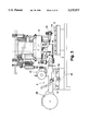
- FIG. 3 is a side view of an apparatus for automatically mounting electronic parts according to this invention.
- FIG. 4 is a schematic view for explanation of the lower end positioned detecting section of an apparatus for automatically mounting electronic parts according to a first embodiment of this invention
- FIG. 5 is a block diagram of a controlling operation of the apparatus for automatically mounting electronic parts according to a first embodiment of this invention
- FIG. 6 is an example of shape data for each of the electronic part stored in a data memory section of an apparatus for automatically mounting electronic parts according to this invention
- FIG. 7 is a flow diagram for explanation of operation of an apparatus for automatically mounting electronic parts according to a first embodiment of this invention.
- FIG. 8 is an explanatory view of a lower end position detecting state by the lower end position detecting section of the apparatus for automatically mounting electronic parts according to a first embodiment of this invention
- FIG. 9 is a partial cross-sectional view for explanation of the lower end position detecting section and the position adjusting mechanism of the apparatus for automatically mounting electronic parts according to a second embodiment of this invention.
- FIG. 10 is a block diagram of an apparatus for automatically mounting electronic parts according to a second embodiment of this invention.
- FIG. 11 is a flow diagram for explanation of operation of the apparatus for automatically mounting electronic parts according to the second embodiment of this invention.
- FIG. 12 is an explanatory plan view of the lower end position detecting state of the lower end position detecting section of the apparatus for automatically mounting electronic parts according to the second embodiment of this invention.
- FIG. 13 is an explanatory side view of the lower end position detecting state of the lower end position detecting section of an apparatus for automatically mounting electronic parts according to the second embodiment of this invention.
- FIG. 14 is an explanatory view of another example of a position adjusting mechanism of the apparatus for automatically mounting electronic parts according to the second embodiment of this invention.
- a Y table 1 moves in the Y direction by rotation of a Y-axis motor 2
- an X table 3 moves in the X direction on the Y table 1 by the rotation of an X-axis motor 4.
- These tables 1 and 3 constitute an XY table for moving a printed substrate 6 mounted on the X table in the XY direction and also compose a parts-mounting station 100.
- the printed substrate 6 carrying a chip-like electronic part (hereinafter referred to as part) 5 is fixed on a not shown fixing means on the X table.
- a plurality of parts feeding devices 8, for feeding parts 5 are provided on a feeding base 7 as a holding station 110 at a position opposed to that of the parts mounting station 100.
- the feeding base 7 is moved in the x direction by a ball screw 10 rotated by a feeding base driving motor 9. Namely, the feeding base 7 moves in the X direction while being guided by the linear guide 12 through the ball screw 10 screwed into the threaded hole 11 fixed to the feeding base 7.
- a rotary table 13 intermittently rotating as a movable base is located between the mounting station 100 and the holding station 110, and a nozzle head (mounting head) 15 having six holding nozzles 14 are provided with a regular interval in accordance with the intermittent pitch of the rotary table 13 at the outer circumference of the rotary table 13.
- the nozzle head 15 stops at the stopping position I indicated by a black dot in the upper middle portion in FIG. 2 such that the holding nozzle 14 picks up and takes out the part 5 from the parts feeding device 8 at the parts collection station 110.
- the holding nozzle 14 picks up the part 5 by the lowering of the mounting head 15 at the stopping position 1.
- the picking up of the part 5 is carried out for example by vacuum sucking.
- the holding nozzle 14 is connected to a vacuum source such as a not shown vacuum pump via a vacuum tube 18 connected to the nozzle head 15.
- a parts identifying station 120 is located between the parts collection station 110 and the parts mounting station 100.
- a camera is provided as the parts identifying device 16.
- the camera images the positional gap of the part 5 picked up by the holding nozzle 14 at the lower surface of the part 5 with a predetermined visual field range and recognizes the imaged part using an identifying processing.
- the stopping position of the nozzle head 15 next to the identifying station 120 is an angle correcting station 130.
- a head rotating device 17 being composed of a robot arm etc. rotates the nozzle head 15 in the 8 direction by an angular amount for correcting the angular positional divergence of the chip part 5 from the identified result of the part identifying device 16 and an angular amount indicated by not shown mounting data.
- the stopping position next but one to the angle correcting station 130 is a mounting station 100 where the part 5 picked up by the holding nozzle 14 is mounted on the printed substrate 6.
- a vertically movable up-down stick 20 engages with a pivot lever 21 of the parts feeding device 8 to pivotally move the pivot lever 21 and intermittently feeds not shown parts storage tape in which the chip parts are inserted with a predetermined interval in accordance with this interval for feeding the chip parts 5 to the parts picking up position of the holding nozzle 14.
- the parts storage tape is wound around a tape reel 22.
- the station next but one to the collection station 110 has a line sensor 27 as a lower end detecting section for detecting the orientation of the part 5 being picked up by the holding nozzle 14.
- the line sensor 27 is composed of a light emitter 28 having a number of vertically arranged light-emitting elements and a light receiver 29 having a number of light-receiving elements (CCD) on the line in the vertical direction.
- the light emitter 28 may be constituted to emit light from an LED which is collected by a lens and projected in parallel, or alternatively a laser can be used.
- the CCD element one being composed of one thousand elements arranged in a vertical width of approximately 10 mm may be used.
- the light amount received by each element can be detected. Therefore, by determining a threshold value of the light receiving amount it can also be used as an ON/OFF sensor. Its ON/OFF output will become height positional data by identifying the portion being interrupted by the part 5 or the holding nozzle 14.
- the line sensor 27 is mounted at a position where the holding nozzle 14 picks up the part 5 by the rotation of the rotary table 13 so that the light projected by the light emitter 28 strikes approximately the center of the holding nozzle 14.
- a controlling block of an automatic electronic parts mounting device will now be described with reference to FIG. 5.
- a CPU 31 controls a variety of operations related to the mounting of the chip parts 5 in accordance with programs stored in a ROM 33, based on a variety of data stored in a RAM 32 and information from sensors such as the line sensor 27.
- the line sensor 27 is coupled to the CPU 31 via the an interface 34.
- An index motor 35 of the rotary table 13 being a control target of the CPU 31 is connected to the CPU 31 via the interface 34 and the driving circuit 36.
- the output of the line sensor 27 is from each CCD element, and a height position at a border between the lowest light-interrupted element and a light-receiving element next to the light-interrupted element is calculated by the CPU as a lower end peak value of the part 5.
- the RAM 32 has an input memory as a latch section for temporarily holding a lower end position detected during the movement and a hold memory 39 as a lower end memory section for holding the lowest end data among the lower end positions being held by the input memory 38.
- the input memory 38 stores data calculated at a regular time interval from the output of the line sensor 27.
- a selecting section 31-1 included in the CPU 31 compares data actually input to the input memory 38 to data previously held in the hold memory 39, and selects the larger one, i.e. the lower one to be stored in the hold memory 39.
- the data memory section of the RAM 32 stores parts data as shown in FIG. 6 for each of the sorts of part.
- This parts data comprises data of parts thickness for comparing with a height position as the lowest end position stored in the hold memory 39 and data of parts thickness tolerance to be used in that comparison.
- a manipulating section not shown is operated to start an automatic operation of the automatic electronic parts mounting apparatus.
- the feeding base 7 then moves in accordance with the data for the mounting order of the parts 5 stored in the RAM 32, to stop the parts supplying device 8 at the collecting position of the holding nozzle 14 of the nozzle head 15, such that the chip part 5 is taken out by the down movement of the nozzle 14.
- the rotary table 13 intermittently rotates via an index mechanism not shown by the rotation of the index motor 35.
- the nozzle head 15 moves to the next station and stops there, and further moves to the parts orientation detecting station 140 having the line sensor 27, by the next rotation.
- the CPU 31 After the nozzle head 15 passes through a position a little bit before stopping at the parts orientation detecting station 140 by the rotation of the rotary table 13, the CPU 31 detects this timing to execute the operations described in the flow diagram of FIG. 7. This timing is detected by the CPU 31 when a not shown sensor for detecting the predetermined rotary angle of the cam shaft which makes one rotation for each intermittent rotation of the rotary table 13 is actuated. As a result, a timing signal is output each time the nozzle head 15 advances a certain distance. This timing signal should preferably be output with the alignment divergence of the parts 5 picked up by the holding nozzle 14 in the moving direction being taken account.
- the size of the part and the alignment divergence are taken into consideration to enable the output of the timing signal to start the detection even though the distal end of the part 5 has not yet, arrived at the light beam position, being the detection point of the line sensor 27.
- the light beam from the light emitter 28 of the line sensor 27 is continuously emitted and is continuously received by the light receiver 29, and the output is continuous. It is also possible to constract it such that at the detection starting timing, the light emitter 28 emits light to start the output of the line sensor 27.
- the input memory 38 and the hold memory 39 are firstly cleared (S1), and the CPU 31 calculates the lowest transit position from the light-interrupted state to the light-receiving state as the lower end peak value which is then stored in the input memory 38 (S2).
- the origin of this value is set to be above the height position of the lower end surface of the holding nozzle 14 in order to make the upper side positive.
- the selecting section 31-1 of the CPU 31 compares this value to the value of the hold memory 39 and stores the larger value in the hold memory 39 (S3-S4). But since there is no part 5 for the initial period, the value remains "0". During this process the nozzle 14 moves, but the CPU 31 executes the same process since it is different from the end timing (S5).
- the CPU 31 receives the output when the position indicated by a second dotted line from the left end in FIG. 8 becomes the position of the light beam of the light emitter 28, a lower end position indicated by the black dots on the dotted lines in FIG. 8 is calculated. The value at this position is stored in the input memory 38.
- That value is then compared to the value of the hold memory 39 and turns out to be larger so as to be input to the hold memory 39. During this process the nozzle 14 moves, and at the time of the next input to the CPU 31, this value will become larger than that of the hold memory 39. As a result, the value of the hold memory 39 is renewed.
- the output from the line sensor 27 is read out at the position of the vertical dotted line in FIG. 8 where the predetermined amount of rotation of the nozzle head is completed.
- the CPU 31 stops reading and the judging section 31-2 compares the value stored in the hold memory i.e. the value of the lowest end position, to a value of corresponding to the parts thickness of the parts data stored in the RAM 32 added to the data at the nozzle level at the lower end position of the holding nozzle 14 (S6). If the difference is out of the parts thickness tolerance and the value in the hold memory is larger, it is judged as abnormal holding (abnormal orientation), and the following processing is executed to correct the abnormality (S7).
- the line sensor 27 In the case of the chip part 5 being normally held, when the part 5 arrives at the station provided with the line sensor 27 by the moving of the mounting head 15, the height level of the lower end surface of the part 5 is detected by the line sensor 27 as aforementioned. Each time the CPU 31 reads the data, the data is stored in the input memory 38 while the lowest end position is stored in the hold memory 39. When the holding is completed normally, the value of the input memory 38 will be approximately constant and the CPU 31 judges if the part orientation is abnormal or not after the detection end timing. Also, in the same manner as aforementioned, the CPU judges as normal since the value is within the parts tolerance in comparison with the nozzle data of the parts data and the lower end position of the parts thickness data(S8), so as to control the following normal processing operations.
- the identifying device 16 executes the identifying process at the identifying station, and the head 15 rotates to cause angular movement of the chip part 5, so as to make fine adjustment, and the chip part 5 is mounted on the printed substrate 6 positioned by the movement of the XY table 3, 1 at the mounting station.
- the down moving distance of the holding nozzle is adjusted in accordance with the lower end position so that the part 5 is mounted on the printed substrate 6 with a proper pressure.
- the value of the hold memory 39 due to the output from the line sensor 27 corresponds to the lower end height position of the holding nozzle 14. As a result, it is judged that there is no part 5. Also in this case, no parts mounting operation is executed, similarly to the processing for an abnormality.
- the CPU 31 judges it abnormal to stop the mounting operation of the part 5 which will then be evacuated at the predetermined evacuating station.
- the line sensor 27 detects the lower end position for the moving part 5 at a time before or after stopping at the stopping station of the rotary table 13, and it is also possible to make the detection for a moving part 5 by providing the line sensor between the stations.
- the lower end position is detected during the rotary movement of the rotary table 13, so that the detecting interval of the lower end position is affected by the rotating speed of the rotary table 13.
- the rotating speed of the rotary table 13 is too large, the reliability of the lower end position detection may be reduced due to excessively expand the detection interval.
- a method for detecting the lower end position which is not affected by the rotation of the rotary table 13.
- the composition of the mounting station 100, the collection station 110, and the parts identifying station 120 are the same as in the previous embodiment so as to be omitted from description.
- the parts posture detecting station 140 is newly provided, and so will be explained in detail.
- the line sensor 27 is composed of the light emitter 28 and the light receiver 29 arranged on a virtual line connecting the center of the mounting head 15 to the rotary center of the rotary table 13, and the light emitter 28 and the light receiver 29 are located at a position with the head 15 therebetween.
- the light beam of the light emitter 28 can be arranged such that the light beam from the light emitter 28 becomes parallel to the virtual line.
- the sensor 27 can be located at a position rotated to a certain extent so long as the moving nozzle 14 does not hit it.
- the mounting head 15 will now be described in detail with reference to FIG. 9
- a mounting plate 51 made of aluminum is provided at the lower end of the shaft 50, and has a pulse motor 52 mounted.
- the rotor 53 of the pulse motor 52 is rotatable in the ⁇ direction within the stator 54 integrally formed with the mounting plate 51.
- the holding nozzles 14 (six, for example) are provided, each of which is movable and passes vertically through the rotor 53.
- the holding nozzle 14 for picking up the part 5 by the rotation of the rotor 53 can be positioned regardless of the movement or stopping of the rotary table 13 at a desired angular position.
- the driving of the pulse motor 52 is carried out under the control of the driving circuit, described hereinafter mentioned, and the driving power source is connected via a cord 19 (see FIG. 3).
- a CPU 60 controls a variety of operations related to the mounting of the chip parts 5 in accordance with the program stored in the ROM 62 on the basis of a variety of data stored in the RAM 61 and information received from the sensors and the like, such as the line sensor 27.
- the line sensor 27 is connected to the CPU 60 via the interface 63.
- the index motor 39 and the pulse motor 52 of the rotary table 13, being the control target of the CPU 60, are connected to the CPU 60 via the interface 63 and the driving circuit 64.
- the output of the line sensor 27 is made from each of the CCDs likewise in the first embodiment, but the height position at the border between the element being light-interrupted at the lowest position and the element receiving light next thereto is calculated as the lower peak value being the lower end position, by the CPU 60.
- the operations of the input memory 65, and the hold memory 66 included in the RAM 61, are the same as in the first embodiment, in which the data at the lowest end position of the part 5 is stored in the hold memory 66.
- the RAM 61 in the same manner as in the first embodiment, contains data for each part as shown in FIG. 6 to be used for the comparison with the lowest end position.
- a manipulating section not shown is operated to start the automatic driving of the automatic electronic parts mounting apparatus.
- the part 5 is picked up.
- the rotary table 13 is then intermittently rotated via an index mechanism not shown by the rotation of the index motor 35.
- the nozzle head 15 moves to and stops at the next station, and further moves to the parts orientation detecting station IV provided with the line sensor 27 by the next rotation.
- the CPU 60 detects the parts orientation as described in the flow diagram of FIG. 11.
- the input memory 65 and the hold memory 66 are cleared (S11), and the pulse motor 52 starts rotating in response to the command from the CPU 60 (S12).
- the light emitter 28 of the line sensor 27 continuously emits a light beam, which is continuously received by the light receiver 29 which continuously generates an output. It is also possible to construct the detection part so that the light emitter 28 emits lights and the output of the line sensor 27 starts when the motor 52 starts rotating or the rotary table 13 stops rotating.
- the CPU 60 then calculates the lowest position of border from light-interrupted to light-received state as the lower end peak value, which is then stored in the input memory 65 (S13). This value is set such that the origin becomes higher than the height position of the lower end surface of the holding nozzle 14 with the lower side positive.
- the selecting section 60-1 of the CPU 60 compares the lower end peak value to the value of the hold memory 66 as in the first embodiment (S14), the stores the larger one in the hold memory 66 (S15). While the CPU 60 performs this process, the nozzle 14 continues rotating. The CPU 60 repeats the same process until the detection end timing (S16).
- the position where the lower end peak value of the chip part 5 is firstly detected is the position of the two-dot chain line connecting between the light emitter 28 and the light receiver 29 in FIG. 12. If the rotating direction of the holding nozzle 14 is in the clockwise direction in FIG. 12, the next detecting position will become the next two-dot chain line in the counterclockwise direction in FIG. 12.
- the peak value of the input memory 65 secondly detected and the value in the hold memory 66 are mutually compared, and if the value of the input memory 65 is larger, the value of the hold memory 66 is renewed to the value of the input memory.
- the lower end peak values of the chip part 5 will be detected with a predetermined interval as shown by way of a two-chain dot line in FIG. 12 as the nozzle 14 rotates by the driving of the pulse motor 52.
- the lower end position can be stored in the hold memory 66 by setting the rotating speed of the motor 52 such that the detecting interval becomes smaller than the lateral thickness T of the lead 67.
- the CPU 60 judges that it is the detection end timing.
- the judging section 60-2 of the CPU 60 compares the value in the hold memory 66 to the part data to be compared and stored in the RAM 61.
- the data to be compared are, in the case a part having the lead 67, the value yielded by adding the thickness value including the lead 67, to the nozzle level data, being the lower end position of the holding nozzle.
- This detection end timing is used because the lower end peak value can be detected for all the parts regardless of their size, just by rotating the pulse motor 52 by 180 degrees. Alternatively, however, it is also possible to set it as the end timing when the motor 52 is rotated by 360 degrees. Further, as shown in FIG. 12, if the size of the part 5 is small, there will be no rotary center of the holding nozzle in the part 5, so that the lower end peak value for all the part 5 can be detected without the need to rotate 180 degrees. In this case, the rotating angle as the detection end timing can be previously set in accordance with the size of the part 5, but alternatively it is also possible to set the holding nozzle 14 at a position where the light from the line sensor 28 is not interrupted by the part 5, by rotating it counter-clockwise in FIG. 12 by the motor 52 before the mounting head 15 stops at the part orientation detecting station IV, so as to detect the lower end peak value by rotating it in accordance with the size of the part 5.
- the pulse motor 52 rotates and the height level of the lower end surface of the part 5 is calculated and supplied to the input memory 65 each time the CPU 60 reads the output of the line sensor 27, and the lowest end position data are stored in the hold memory 66.
- the value in the input memory 65 does not exceed a predetermined value, so that the CPU 60 judges that there is no part orientation abnormality after the detection end timing.
- the CPU 60 compares the lowest end position to the lower end position from the nozzle data of the parts data and the part thickness data, and judges as correct when it is within the tolerance, and controls the following normal processing operations (S19).
- the identifying device 16 executes identifying process at the identifying station 120.
- the head rotating device 17 adjusted the angle of the part 5 on the basis of the identified result in the identifying device 16, but in this second embodiment, instead of using the head rotating device 17, the pulse motor 52 rotates to control the angle of the part 5 on the basis of the identified result.
- the chip part 5 is mounted on the printed substrate 6 positioned by the movement of the XY table 3, 1.
- the descending distance of the holding nozzle 14 is adjusted to accord to the lower end position, and the part 5 is then mounted on the printed substrate 6 by a proper pressure.
- the processing to correct the abnormality such as non-collection of the part 5, entoneous picking up of a different part etc. will be executed in the same manner as in the first embodiment.
- the orientation abnormality of the part 5 is judged each time when the part 5 moves to the part orientation detecting station 140 of the line sensor 27, for suitable treatment.
- the reading of the output from the next line sensor 27, by the CPU has been made immediately after the processing of calculation of the lower end position and the comparison of the data in the input memory to that of the hold memory etc., but it is alternatively possible to set the reading interval to be longer and to perform other processes during this interval, or to provide the functions shown in FIGS. 7 and 11 as a processing unit composed of an input memory and a hold memory which is connected to the CPU of the automatic electronic parts mounting apparatus via an interface, while the other side is coupled to the line sensor.
- the CPU of the mounting apparatus it is also possible for the CPU of the mounting apparatus to supply the detection starting timing and the detection end timing synchronously with the rotation of the adsorptive nozzle 14, and for the contents of the hold memory, after the detection end, to be read by the CPU of the mounting apparatus to judge the abnormality.
- the lower end peak value for the entire surface of the part 5 is detected by rotating the pulse motor 52 at the parts detecting station, but it is also possible to carry out the similar detection by rotating the line sensor 27 by the pulse motor 68 as shown in FIG. 14, such that the light axis passes across the entire surface of the part.
- the stopping time of the rotary table 13 may be extended.
- the lower end position has been calculated by adding the part thickness data and the nozzle level data stored in the RAM 36 in the aforementioned embodiments, it is also possible to directly store the lower end position data therein.
- the lowest end position has been decided by comparing the actually input lower end position to the previously input lower end position, but it is also possible to select the lowest end position after a plurality of such positions are input.
- the rotor 53 having a plurality of nozzle heads 15 has been rotated by the holding nozzle 14, but it is also possible for the adsorptive nozzle itself provided in the mounting head to be able to rotate to be capable of being detected by the line sensor.
Abstract
Description
Claims (14)
Applications Claiming Priority (4)
| Application Number | Priority Date | Filing Date | Title |
|---|---|---|---|
| JP27237793A JP3223009B2 (en) | 1993-10-29 | 1993-10-29 | Electronic component automatic mounting device |
| JP5-272377 | 1993-10-29 | ||
| JP5-288251 | 1993-11-17 | ||
| JP05288251A JP3128409B2 (en) | 1993-11-17 | 1993-11-17 | Electronic component automatic mounting device and electronic component mounting method |
Publications (1)
| Publication Number | Publication Date |
|---|---|
| US5539977A true US5539977A (en) | 1996-07-30 |
Family
ID=26550168
Family Applications (1)
| Application Number | Title | Priority Date | Filing Date |
|---|---|---|---|
| US08/330,749 Expired - Lifetime US5539977A (en) | 1993-10-29 | 1994-10-28 | Apparatus and method for automatically mounting electronic parts |
Country Status (4)
| Country | Link |
|---|---|
| US (1) | US5539977A (en) |
| EP (1) | EP0652699B1 (en) |
| KR (1) | KR100329586B1 (en) |
| DE (1) | DE69404015T2 (en) |
Cited By (25)
| Publication number | Priority date | Publication date | Assignee | Title |
|---|---|---|---|---|
| US5727300A (en) * | 1995-02-07 | 1998-03-17 | The Boeing Company | Fastener verification system |
| US5864944A (en) * | 1996-01-08 | 1999-02-02 | Matsushita Electric Industrial Co., Ltd. | Mounting apparatus of electronic components and mounting methods of the same |
| US5889675A (en) * | 1995-07-13 | 1999-03-30 | Mitsubishi Denki Kabushiki Kaisha | Pickup device |
| US5926950A (en) * | 1995-12-28 | 1999-07-27 | Fuji Machine Mfg. Co., Ltd. | Electronic component transferring device and method, and electronic component mounting system and method |
| US5953812A (en) * | 1997-07-03 | 1999-09-21 | Schlumberger Technologies, Inc. | Misinsert sensing in pick and place tooling |
| US6061900A (en) * | 1997-01-31 | 2000-05-16 | Sanyo Electric Co., Ltd. | Lift cam mechanism for electronic parts-mounting apparatus |
| WO2000045230A1 (en) * | 1999-01-29 | 2000-08-03 | Bp Microsystems, Inc. | Pick and place teaching method and apparatus |
| US6178620B1 (en) * | 1996-07-19 | 2001-01-30 | Matsushita Electric Industrial Co., Ltd. | Electronic component feeding apparatus |
| US6336548B1 (en) | 1995-12-28 | 2002-01-08 | Fuji Machine Mfg. Co., Ltd. | Apparatus for positioning electronic component holder head and apparatus for transferring electronic component |
| US20020035781A1 (en) * | 2000-09-25 | 2002-03-28 | Matsushita Electric Industrial Co., Ltd. | Automatic electronic parts mounting apparatus |
| US20020178578A1 (en) * | 2000-09-19 | 2002-12-05 | Kenji Okamoto | Component suction device, component mounting apparatus and component mounting method |
| US6550134B2 (en) * | 1998-01-29 | 2003-04-22 | Fuji Machine Mfg. Co., Ltd. | Electric-component transferring apparatus, method of taking images of electric components, and electric-component mounting system |
| US6681468B1 (en) * | 1999-11-05 | 2004-01-27 | Matsushita Electric Industrial Co., Ltd. | Device and method for mounting parts |
| US6862803B2 (en) * | 2000-08-29 | 2005-03-08 | Matsushita Electric Industrial Co., Ltd. | Method for mounting electronic component |
| US20050166392A1 (en) * | 2002-12-10 | 2005-08-04 | Hitachi High-Tech Instruments Co., Ltd. | Electronic component mounting apparatus |
| US20050172770A1 (en) * | 2000-09-28 | 2005-08-11 | Sanyo Electric Co., Ltd. | Linear motor and electronic component feeding apparatus |
| US20050250223A1 (en) * | 2004-04-27 | 2005-11-10 | Hitachi High-Tech Instruments Co., Ltd. | Electronic component mounting method and electronic component mounting apparatus |
| US20060021215A1 (en) * | 2004-07-30 | 2006-02-02 | Hitachi High-Tech Instruments Co., Ltd. | Electronic component mounting apparatus |
| US20070011869A1 (en) * | 2005-06-30 | 2007-01-18 | Hitachi High-Tech Instruments Co., Ltd. | Electronic component mounting apparatus |
| US20070130756A1 (en) * | 2005-11-30 | 2007-06-14 | Hitachi High-Tech Instruments Co., Ltd. | Electronic component mounting apparatus |
| US20100018165A1 (en) * | 2008-07-23 | 2010-01-28 | Stephen Francis Kudia | Stretch Wrapping System and Process |
| USRE44384E1 (en) * | 1997-07-07 | 2013-07-23 | Panasonic Corporation | Method and device for mounting electronic component |
| JP2018006417A (en) * | 2016-06-28 | 2018-01-11 | 富士機械製造株式会社 | Determination device |
| US20180352691A1 (en) * | 2015-07-28 | 2018-12-06 | Fuji Machine Mfg.Co., Ltd. | Component mounting machine |
| US10448551B2 (en) | 2015-05-25 | 2019-10-15 | Fuji Corporation | Component mounter |
Families Citing this family (3)
| Publication number | Priority date | Publication date | Assignee | Title |
|---|---|---|---|---|
| JP4681174B2 (en) | 2001-09-28 | 2011-05-11 | 株式会社日立ハイテクインスツルメンツ | Electronic component automatic mounting device |
| KR100742314B1 (en) * | 2005-11-23 | 2007-07-24 | 서울전력주식회사 | Illumination Apparatus For Lotus Lamp Using Internal Power Supply |
| CN107498307B (en) * | 2017-10-23 | 2023-05-16 | 浙江盛越电子科技有限公司 | Full-automatic motor assembly machine and assembly method thereof |
Citations (12)
| Publication number | Priority date | Publication date | Assignee | Title |
|---|---|---|---|---|
| JPS60121671A (en) * | 1983-12-02 | 1985-06-29 | Yuasa Battery Co Ltd | Manufacture of alkaline battery |
| DE3532500A1 (en) * | 1984-09-17 | 1986-03-27 | TDK Corporation, Tokio/Tokyo | METHOD AND ARRANGEMENT FOR ASSEMBLING CIRCUIT BOARDS |
| US4706379A (en) * | 1984-08-31 | 1987-11-17 | Matsushita Electric Industrial Co., Ltd. | Parts mounting apparatus |
| EP0293175A2 (en) * | 1987-05-28 | 1988-11-30 | Sanyo Electric Co., Ltd. | Parts mounting apparatus |
| US4868973A (en) * | 1987-08-12 | 1989-09-26 | Hitachi, Ltd. | Apparatus for mounting electric parts |
| US4905370A (en) * | 1987-01-14 | 1990-03-06 | Sanyo Electric Co., Ltd. | Electronic parts automatic mounting apparatus |
| US5003692A (en) * | 1989-05-17 | 1991-04-02 | Matsushita Electric Industrial Co., Ltd. | Electric component mounting method |
| US5031309A (en) * | 1988-07-26 | 1991-07-16 | Samsung Electronics Co., Ltd. | Component assembling machine driving method |
| US5212881A (en) * | 1990-09-20 | 1993-05-25 | Tokico Ltd. | Electronic component mounting apparatus |
| US5224262A (en) * | 1991-03-28 | 1993-07-06 | Matsushita Electric Industrial Co., Ltd. | Parts mounting machine |
| US5377405A (en) * | 1992-07-01 | 1995-01-03 | Yamaha Hatsudoki Kabushiki Kaisha | Method for mounting components and an apparatus therefor |
| US5384956A (en) * | 1992-07-01 | 1995-01-31 | Yamaha Hatsudoki Kabushiki Kaisha | Method for mounting components |
-
1994
- 1994-10-28 US US08/330,749 patent/US5539977A/en not_active Expired - Lifetime
- 1994-10-28 DE DE69404015T patent/DE69404015T2/en not_active Expired - Lifetime
- 1994-10-28 EP EP94117101A patent/EP0652699B1/en not_active Expired - Lifetime
- 1994-10-28 KR KR1019940027849A patent/KR100329586B1/en not_active IP Right Cessation
Patent Citations (13)
| Publication number | Priority date | Publication date | Assignee | Title |
|---|---|---|---|---|
| JPS60121671A (en) * | 1983-12-02 | 1985-06-29 | Yuasa Battery Co Ltd | Manufacture of alkaline battery |
| US4706379A (en) * | 1984-08-31 | 1987-11-17 | Matsushita Electric Industrial Co., Ltd. | Parts mounting apparatus |
| US4881319A (en) * | 1984-09-17 | 1989-11-21 | Tdk Corporation | Process for mounting chip type circuit elements on printed circuit boards and apparatus therefor |
| DE3532500A1 (en) * | 1984-09-17 | 1986-03-27 | TDK Corporation, Tokio/Tokyo | METHOD AND ARRANGEMENT FOR ASSEMBLING CIRCUIT BOARDS |
| US4905370A (en) * | 1987-01-14 | 1990-03-06 | Sanyo Electric Co., Ltd. | Electronic parts automatic mounting apparatus |
| EP0293175A2 (en) * | 1987-05-28 | 1988-11-30 | Sanyo Electric Co., Ltd. | Parts mounting apparatus |
| US4868973A (en) * | 1987-08-12 | 1989-09-26 | Hitachi, Ltd. | Apparatus for mounting electric parts |
| US5031309A (en) * | 1988-07-26 | 1991-07-16 | Samsung Electronics Co., Ltd. | Component assembling machine driving method |
| US5003692A (en) * | 1989-05-17 | 1991-04-02 | Matsushita Electric Industrial Co., Ltd. | Electric component mounting method |
| US5212881A (en) * | 1990-09-20 | 1993-05-25 | Tokico Ltd. | Electronic component mounting apparatus |
| US5224262A (en) * | 1991-03-28 | 1993-07-06 | Matsushita Electric Industrial Co., Ltd. | Parts mounting machine |
| US5377405A (en) * | 1992-07-01 | 1995-01-03 | Yamaha Hatsudoki Kabushiki Kaisha | Method for mounting components and an apparatus therefor |
| US5384956A (en) * | 1992-07-01 | 1995-01-31 | Yamaha Hatsudoki Kabushiki Kaisha | Method for mounting components |
Non-Patent Citations (1)
| Title |
|---|
| European Search Report, dated Feb. 2, 1995, Appl. No. 94117101.9. * |
Cited By (35)
| Publication number | Priority date | Publication date | Assignee | Title |
|---|---|---|---|---|
| US5727300A (en) * | 1995-02-07 | 1998-03-17 | The Boeing Company | Fastener verification system |
| US5889675A (en) * | 1995-07-13 | 1999-03-30 | Mitsubishi Denki Kabushiki Kaisha | Pickup device |
| US5926950A (en) * | 1995-12-28 | 1999-07-27 | Fuji Machine Mfg. Co., Ltd. | Electronic component transferring device and method, and electronic component mounting system and method |
| US6336548B1 (en) | 1995-12-28 | 2002-01-08 | Fuji Machine Mfg. Co., Ltd. | Apparatus for positioning electronic component holder head and apparatus for transferring electronic component |
| US5864944A (en) * | 1996-01-08 | 1999-02-02 | Matsushita Electric Industrial Co., Ltd. | Mounting apparatus of electronic components and mounting methods of the same |
| US6178620B1 (en) * | 1996-07-19 | 2001-01-30 | Matsushita Electric Industrial Co., Ltd. | Electronic component feeding apparatus |
| US6061900A (en) * | 1997-01-31 | 2000-05-16 | Sanyo Electric Co., Ltd. | Lift cam mechanism for electronic parts-mounting apparatus |
| US5953812A (en) * | 1997-07-03 | 1999-09-21 | Schlumberger Technologies, Inc. | Misinsert sensing in pick and place tooling |
| USRE44384E1 (en) * | 1997-07-07 | 2013-07-23 | Panasonic Corporation | Method and device for mounting electronic component |
| US6550134B2 (en) * | 1998-01-29 | 2003-04-22 | Fuji Machine Mfg. Co., Ltd. | Electric-component transferring apparatus, method of taking images of electric components, and electric-component mounting system |
| WO2000045230A1 (en) * | 1999-01-29 | 2000-08-03 | Bp Microsystems, Inc. | Pick and place teaching method and apparatus |
| US6587743B1 (en) | 1999-01-29 | 2003-07-01 | B P Microsystems, Inc. | Pick and place teaching method and apparatus for implementing the same |
| US6681468B1 (en) * | 1999-11-05 | 2004-01-27 | Matsushita Electric Industrial Co., Ltd. | Device and method for mounting parts |
| US6862803B2 (en) * | 2000-08-29 | 2005-03-08 | Matsushita Electric Industrial Co., Ltd. | Method for mounting electronic component |
| US20020178578A1 (en) * | 2000-09-19 | 2002-12-05 | Kenji Okamoto | Component suction device, component mounting apparatus and component mounting method |
| US7017261B2 (en) * | 2000-09-19 | 2006-03-28 | Matsushita Electric Industrial Co., Ltd. | Component suction device, component mounting apparatus and component mounting method |
| US20020035781A1 (en) * | 2000-09-25 | 2002-03-28 | Matsushita Electric Industrial Co., Ltd. | Automatic electronic parts mounting apparatus |
| US20050172770A1 (en) * | 2000-09-28 | 2005-08-11 | Sanyo Electric Co., Ltd. | Linear motor and electronic component feeding apparatus |
| US20050166392A1 (en) * | 2002-12-10 | 2005-08-04 | Hitachi High-Tech Instruments Co., Ltd. | Electronic component mounting apparatus |
| US20050250223A1 (en) * | 2004-04-27 | 2005-11-10 | Hitachi High-Tech Instruments Co., Ltd. | Electronic component mounting method and electronic component mounting apparatus |
| US7533459B2 (en) * | 2004-04-27 | 2009-05-19 | Hitachi High-Tech Instruments, Co., Ltd. | Electronic component mounting method and electronic component mounting apparatus |
| US20060021215A1 (en) * | 2004-07-30 | 2006-02-02 | Hitachi High-Tech Instruments Co., Ltd. | Electronic component mounting apparatus |
| US20070011869A1 (en) * | 2005-06-30 | 2007-01-18 | Hitachi High-Tech Instruments Co., Ltd. | Electronic component mounting apparatus |
| US20090119912A1 (en) * | 2005-06-30 | 2009-05-14 | Hitachi High-Tech Instruments Co., Ltd. | Electronic component mounting apparatus |
| US8181337B2 (en) | 2005-06-30 | 2012-05-22 | Hitachi High-Tech Instruments Co., Ltd. | Electronic component mounting method |
| US20100186223A1 (en) * | 2005-11-30 | 2010-07-29 | Hitachi High-Tech Instruments Co., Ltd. | Electronic component mounting apparatus |
| US7712208B2 (en) | 2005-11-30 | 2010-05-11 | Hitachi High-Tech Instruments Co., Ltd. | Electronic component mounting apparatus |
| US8336195B2 (en) | 2005-11-30 | 2012-12-25 | Hitachi High-Tech Instruments Co., Ltd. | Electronic component mounting apparatus |
| US20070130756A1 (en) * | 2005-11-30 | 2007-06-14 | Hitachi High-Tech Instruments Co., Ltd. | Electronic component mounting apparatus |
| US20100018165A1 (en) * | 2008-07-23 | 2010-01-28 | Stephen Francis Kudia | Stretch Wrapping System and Process |
| US9676507B2 (en) * | 2008-07-23 | 2017-06-13 | Best Packaging, Inc. | Stretch wrapping system and process |
| US10448551B2 (en) | 2015-05-25 | 2019-10-15 | Fuji Corporation | Component mounter |
| US20180352691A1 (en) * | 2015-07-28 | 2018-12-06 | Fuji Machine Mfg.Co., Ltd. | Component mounting machine |
| US10716249B2 (en) * | 2015-07-28 | 2020-07-14 | Fuji Corporation | Component mounting machine |
| JP2018006417A (en) * | 2016-06-28 | 2018-01-11 | 富士機械製造株式会社 | Determination device |
Also Published As
| Publication number | Publication date |
|---|---|
| EP0652699B1 (en) | 1997-07-02 |
| DE69404015T2 (en) | 1998-02-12 |
| DE69404015D1 (en) | 1997-08-07 |
| EP0652699A1 (en) | 1995-05-10 |
| KR100329586B1 (en) | 2002-09-19 |
| KR950013343A (en) | 1995-05-17 |
Similar Documents
| Publication | Publication Date | Title |
|---|---|---|
| US5539977A (en) | Apparatus and method for automatically mounting electronic parts | |
| EP0725560B1 (en) | Mounting device for mounting electric and/or electronic parts | |
| EP0578136B1 (en) | Method for mounting components and an apparatus therefor | |
| US5003692A (en) | Electric component mounting method | |
| EP0715493B1 (en) | Method for mounting chip components and apparatus therefor | |
| US5619328A (en) | Component mounter and recognition method | |
| US7155817B2 (en) | Apparatus and method for mounting components on substrate | |
| US6463653B1 (en) | Component alignment apparatuses | |
| US5467186A (en) | Attracting nozzle control apparatus for a chip component mounting machine | |
| EP0660657A1 (en) | Method and mounting device for mounting a component at a specific position | |
| EP0582086B2 (en) | Method for mounting components and an apparatus therefor | |
| US7367117B2 (en) | Electronic component mounting apparatus and electronic component mounting method | |
| US6634091B1 (en) | Part mounter | |
| US20090135251A1 (en) | Method and apparatus for evaluating a component pick action in an electronics assembly machine | |
| KR19980026672A (en) | Compensator for Electronic Component Mounter and Method | |
| JP4715009B2 (en) | How to recognize workpiece reference marks | |
| JP3223009B2 (en) | Electronic component automatic mounting device | |
| JP2872092B2 (en) | Component mounting method and device | |
| JP2000013097A (en) | Part mounting system | |
| JP3133588B2 (en) | Electronic component automatic mounting device and electronic component mounting method | |
| JP2001156498A (en) | Method of detecting brought-back electronic component in surface-mounting machine | |
| JPH07142895A (en) | Automatic mounting apparatus for electronic component and method for mounting electronic component | |
| EP0833555B1 (en) | Method and mounting device for mounting a component at a specific position | |
| KR100515446B1 (en) | Electronic component mounting device and mounting control method | |
| JP3354272B2 (en) | Electronic component automatic mounting device and electronic component mounting method |
Legal Events
| Date | Code | Title | Description |
|---|---|---|---|
| AS | Assignment |
Owner name: SANYO ELECTRIC CO., LTD., JAPAN Free format text: ASSIGNMENT OF ASSIGNORS INTEREST;ASSIGNORS:KANO, YOSHINORI;TAKATA, KAZUNORI;REEL/FRAME:007202/0540 Effective date: 19941020 |
|
| STCF | Information on status: patent grant |
Free format text: PATENTED CASE |
|
| FEPP | Fee payment procedure |
Free format text: PAYOR NUMBER ASSIGNED (ORIGINAL EVENT CODE: ASPN); ENTITY STATUS OF PATENT OWNER: LARGE ENTITY |
|
| FPAY | Fee payment |
Year of fee payment: 4 |
|
| AS | Assignment |
Owner name: HITACHI HIGH-TECH INSTRUMENTS CO., LTD., JAPAN Free format text: ASSIGNMENT OF ASSIGNORS INTEREST;ASSIGNOR:SANYO ELECTRIC CO., LTD.;REEL/FRAME:014409/0469 Effective date: 20030530 |
|
| FPAY | Fee payment |
Year of fee payment: 8 |
|
| FPAY | Fee payment |
Year of fee payment: 12 |
|
| AS | Assignment |
Owner name: YAMAHA HATSUDOKI KABUSHIKI KAISHA, JAPAN Free format text: ASSIGNMENT OF ASSIGNORS INTEREST;ASSIGNOR:HITACHI HIGH-TECH INSTRUMENTS CO., LTD.;REEL/FRAME:035199/0642 Effective date: 20150201 |