US5539159A - Handwriting capture device - Google Patents
Handwriting capture device Download PDFInfo
- Publication number
- US5539159A US5539159A US08/356,802 US35680294A US5539159A US 5539159 A US5539159 A US 5539159A US 35680294 A US35680294 A US 35680294A US 5539159 A US5539159 A US 5539159A
- Authority
- US
- United States
- Prior art keywords
- digitizer
- receipt
- capture device
- signature
- clamp
- Prior art date
- Legal status (The legal status is an assumption and is not a legal conclusion. Google has not performed a legal analysis and makes no representation as to the accuracy of the status listed.)
- Expired - Lifetime
Links
Images

Classifications
-
- G—PHYSICS
- G06—COMPUTING; CALCULATING OR COUNTING
- G06F—ELECTRIC DIGITAL DATA PROCESSING
- G06F3/00—Input arrangements for transferring data to be processed into a form capable of being handled by the computer; Output arrangements for transferring data from processing unit to output unit, e.g. interface arrangements
- G06F3/01—Input arrangements or combined input and output arrangements for interaction between user and computer
- G06F3/03—Arrangements for converting the position or the displacement of a member into a coded form
- G06F3/033—Pointing devices displaced or positioned by the user, e.g. mice, trackballs, pens or joysticks; Accessories therefor
- G06F3/039—Accessories therefor, e.g. mouse pads
- G06F3/0393—Accessories for touch pads or touch screens, e.g. mechanical guides added to touch screens for drawing straight lines, hard keys overlaying touch screens or touch pads
-
- G—PHYSICS
- G06—COMPUTING; CALCULATING OR COUNTING
- G06F—ELECTRIC DIGITAL DATA PROCESSING
- G06F3/00—Input arrangements for transferring data to be processed into a form capable of being handled by the computer; Output arrangements for transferring data from processing unit to output unit, e.g. interface arrangements
- G06F3/01—Input arrangements or combined input and output arrangements for interaction between user and computer
- G06F3/03—Arrangements for converting the position or the displacement of a member into a coded form
- G06F3/041—Digitisers, e.g. for touch screens or touch pads, characterised by the transducing means
Definitions
- the present invention relates to signature capture devices and more specifically to a handwriting capture device.
- Allgeier et al. discloses a write input device employing a display underneath a transparent digitizer to capture signature information. The display gives a customer feedback for stylus input.
- pressure-sensitive resistive membrane digitizers is subject to false actuations, including those caused by finger contact. If the digitizer is shorted by finger contact during signing, the digitized points representing the signature will be obscured by the finger points, resulting in random scribbling in place of the signature.
- the sensitivity of a pressure-sensitive digitizer is determined by the density of the spacer dot pattern, which maintains separation between the top and bottom sheets of the digitizer.
- a high pattern density requires more writing force to capture a signature. In systems without displays or other sources of immediate feedback, it is essential that the digitizer be sensitive to writing force.
- a handwriting capture device in accordance with the teachings of the present invention, includes a housing having a top surface, a pressure-sensitive digitizer having a low pattern density and mounted in the top surface, circuitry for sensing the presence of a receipt and activating the digitizer, circuitry for processing signature information from the digitizer, and a clamp for retaining the receipt in place over the digitizer.
- the clamp also serves to minimize finger contact with the digitizer.
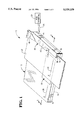
- FIG. 1 is a perspective view of a first embodiment of the handwriting capture device of the present invention
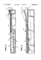
- FIG. 2 is a sectional view of the handwriting capture device taken along line 2--2 of FIG. 1.
- FIG. 3 is a sectional view of the handwriting capture device of the present invention taken along lines 3--3 of FIG. 1;
- FIG. 4 is a perspective view of a second embodiment of the handwriting capture device of the present invention.
- FIG. 5 is a sectional view of the handwriting capture device of the present invention taken along line 5--5 of FIG. 4.
- the handwriting capture device 10 includes a housing 12 having a bottom supporting surface 14 and a top surface 16.
- the housing 12 is generally rectangular in shape.
- the handwriting capture device 10 is lightweight and portable.
- the left end of the housing 12 is sufficient in width and depth to facilitate grasping of the housing 12.
- a pressure-sensitive digitizer 18 Within the top surface 16 is a pressure-sensitive digitizer 18, although other types of digitizers are also envisioned.
- the digitizer 18 is sensitive to signing forces greater than or equal to a predetermined minimum signing force, which is no more than about 10 to 15 grams. When a pen is used, the digitizer has a sensitivity sufficient to capture a handwriting that produces a legible ink impression on the receipt.
- a digitizer manufactured by W. H. Brady & Co. and having a part number 2500044089 is used. This digitizer has a near separation between dots of 0.2 inches. Dot separations higher than 0.2 are not recommended because spurious digitizer readings are more likely to occur. Digitizers having dot separations as low as 0.16 inches may be used in the present invention to achieve valid handwriting capture.
- a thin layer of urethane rubber 19 is affixed to the top surface of the digitizer 18.
- the urethane rubber 19 provides a high friction surface for keeping the receipt 22 in place.
- a signature line 20 on the upper surface 16 and to the left of the digitizer acts as a guide for lining up a receipt 22 having a signature line 21.
- the electronic processing circuitry 24 for operating the digitizer 18 and for controlling information flow from the digitizer 18 to a point-of-service (POS) terminal.
- the digitizer 18 is coupled to the electronic circuitry 24 by a wire connector 27 and the electronic circuitry 24 is coupled to the POS terminal by a wire cable 26.
- the housing may also include circuitry 25 for sensing the presence of the receipt 22 and activating the digitizer 18.
- circuitry 25 includes a commercially available optical switch having an emitting side and a receiving side, both on opposite sides of the receipt. The sensing circuit 25 activates data capture by the digitizer 18 when the receipt 22 is in position under a clamp 30 so as to minimize acceptance of false actuations.
- the paper receipt 22 from the POS terminal is properly aligned and held in place during movement of the device 10 by the clamp 30 which is integrally located on the top surface 16 at the right end of the housing 12.
- the clamp 30 includes an inverted, generally L-shaped member 32 having an inner surface 34.
- a vertical portion 36 of the inner surface 34 provides a stop against which the receipt 22 is aligned.
- a horizontal portion 38 of the inner surface 34 holds the receipt 22 in contact with the top surface 16 of the housing 12. The distance from the horizontal surface 38 to the top surface 16 is sufficient to allow a receipt 22 to pass between the two surfaces.
- the clamp 30 also includes an upwardly flared portion 40 at one end to facilitate insertion of the receipt 22 into the clamp 30.
- the horizontal portion 38 of the inner surface 34 includes downwardly facing protrusions 42 which are generally hemispherical in shape in order to fixedly retain the receipt 22 in place.
- Correspondingly shaped receptacles or dimples 44 are located in the top surface 16 below the protrusions 42. In combination, the dimples 44 and protrusions 42 act to increase the frictional force between the top surface 16 and the receipt 22, thereby effectively retarding movement of the receipt 22 out of the clamp 30.
- a POS operator inserts the right edge of the receipt into the clamp 30, starting at the upwardly flared portion 40.
- the receipt 22 is further inserted until the signature line 21 is properly aligned with the signature line 20 on the top surface 16 of the housing 12. In this position, the receipt 22 will also be properly aligned with the vertical surface 36 of the clamp 30 and properly engaged between the dimples 44 and the protrusions 42.
- the sensing circuitry 25 activates data capture by the digitizer 18.
- a customer signs his name with a writing device, such as a pen, on the signature line 21.
- the handwriting capture device 10 is lightweight and can be easily transferred from person to person without dropping the receipt 22.
- the preferred embodiment 50 includes a housing 52 having a top surface 54, electronic processing circuitry 56 within the housing 52, sensing circuitry 57 within the clamp 30, and a digitizer 18 within the top surface 54.
- a thin layer of urethane rubber 19 is affixed to the top surface of the digitizer 18 to provide a high friction surface for keeping the receipt 22 in place.
- the electronic processing circuitry 56 is coupled to the digitizer 18 through a wire connector 60 and to a POS terminal through a wire cable 62.
- the housing 52 includes a top member 63 and a base member 64 which is inclined to facilitate writing.
- the housing 52 includes a guide member 66 on the top surface 54 at one end of the housing 52.
- the guide member 66 has a vertical guide surface 68 against which the receipt 22 is aligned.
- the housing 52 is sufficient in width and depth to facilitate grasping of the housing 52.
- the preferred embodiment also includes a clamp 70 for retaining the receipt 22 in place during movement of the device 50.
- the clamp 70 includes a frame member 72 which is generally rectangular in shape and which is made of transparent plastic to allow a customer to view the itemized information on the receipt 22 while signing.
- the clamp 70 is anchored at its left end and its right end is biased against the top surface 54 of the housing 52.
- Centrally located within the clamp 70 is a rectangular window 76 exposing the digitizer 18 below.
- the window 76 facilitates proper installation of the receipt 22 over the digitizer 18 and serves to quickly orient a customer with the correct location 78 for signing.
- the clamp 70 may also include an upwardly flared portion 74 for facilitating insertion of the receipt 22 under the clamp.
- the clamp 70 also serves to minimize finger contact with the digitizer 18.
- the clamp 70 includes a vertical rib 80 extending across the clamp 70 for guarding the digitizer 18 from the thumb of the left hand of a customer writing with his right hand and also restricts access to the digitizer 18 by a customer writing with his left hand.
- the frame member 72 blocks contact with the digitizer 18 by the right hand.
- the window 76 provides insufficient room for finger placement, forcing finger placement on the pen to be a predetermined distance upwards from the pen tip for both right and left-handed customers.
- a POS operator holds the device 50 in one hand and inserts the receipt using the other hand by slipping the receipt 22 under the upwardly flared portion 74 until the receipt 22 rests against the vertical guide surface 68 and the signature line 78 or box 79 is within the window 76.
- a customer signs his name with a writing device, such as a pen, on the signature line 78.
- the clamp design facilitates one-handed insertion of the receipt 22.
- the handwriting capture device 50 is lightweight and can be easily transferred from person to person without dropping the receipt 22.
Abstract
A handwriting capture device which employs a highly sensitive digitizer to accurately capture signature information entered using a writing force greater than or equal to a predetermined writing force. The handwriting capture device includes a housing having a top surface, a resistive membrane digitizer mounted in the top surface and having a low pattern density, a layer of urethane rubber for frictionally holding the receipt in place, circuitry for processing digitizer information, a clamp for retaining a receipt in place over the digitizer during movement of the device, and circuitry for sensing the presence of the receipt and for activating data capture by the digitizer when the receipt is positioned under the clamp. In the preferred embodiment, the clamp also serves to minimize finger contact with the digitizer.
Description
This application is a continuation of application Ser. No. 08/033,690 filed Aug. 12, 1993 and issued as U.S. Pat. No. 5,380,958; which is a continuation of application Ser. No. 07/878,671 filed May 5, 1992 and issued as U.S. Pat. No. 5,227,590; which is a continuation of application Ser. No. 07/703,430 filed May 17, 1991 and issued as U.S. Pat. No. 5,120,906.
The present invention relates to signature capture devices and more specifically to a handwriting capture device.
Today, retailers are burdened with having to store and retrieve large amounts of paper records from credit and check transactions. Normally, these records are produced at a retail terminal as master copies of sales receipts, and which are removed from the terminal at the end of the business day for balancing and entry into accounting journals and shipment to processing and storage facilities. Allgeier et al. discloses a write input device employing a display underneath a transparent digitizer to capture signature information. The display gives a customer feedback for stylus input.
While the Allgeier et al. device works well, having a liquid crystal display makes it expensive. Therefore, it would be desirable to eliminate the display and reduce the cost by using a low-cost resistive membrane digitizer. The low-cost resistive membrane must function in response to minimal signing force applied by an ordinary writing instrument such as a pen.
The use of pressure-sensitive resistive membrane digitizers is subject to false actuations, including those caused by finger contact. If the digitizer is shorted by finger contact during signing, the digitized points representing the signature will be obscured by the finger points, resulting in random scribbling in place of the signature.
The sensitivity of a pressure-sensitive digitizer is determined by the density of the spacer dot pattern, which maintains separation between the top and bottom sheets of the digitizer. The more dense the pattern is, the more resistant the digitizer is to finger actuation. However, a high pattern density requires more writing force to capture a signature. In systems without displays or other sources of immediate feedback, it is essential that the digitizer be sensitive to writing force.
Therefore, it would be desirable to provide a handwriting capture device without a display, but having a digitizer sensitive to minimal writing force.
In accordance with the teachings of the present invention, a handwriting capture device is provided. The handwriting capture device includes a housing having a top surface, a pressure-sensitive digitizer having a low pattern density and mounted in the top surface, circuitry for sensing the presence of a receipt and activating the digitizer, circuitry for processing signature information from the digitizer, and a clamp for retaining the receipt in place over the digitizer. In the preferred embodiment, the clamp also serves to minimize finger contact with the digitizer.
It is accordingly an object of the present invention to provide a handwriting capture device.
It is another object of the present invention to provide a handwriting capture device, which is less expensive than a handwriting capture device employing a liquid crystal display mounted beneath a transparent digitizer.
It is another object of the present invention to provide a handwriting capture device which employs a highly sensitive low-cost digitizer which can capture signatures entered using minimal force from an ordinary writing instrument, such as a ballpoint pen.
It is another object of the present invention to provide a handwriting capture device which employs a clamp for holding a pre-printed receipt in place over the digitizer for signature.
It is another object of the present invention to provide a handwriting capture device which employs a clamp for holding a pre-printed receipt in place over the digitizer for signature and which minimizes finger contact with the digitizer.
It is another object of the present invention to provide a handwriting capture device which is lightweight, hand-held, and portable.
Additional benefits and advantages of the present invention will become apparent to those skilled in the art to which this invention relates from the subsequent description of the preferred embodiments and the appended claims, taken in conjunction with the accompanying drawings, in which:
FIG. 1 is a perspective view of a first embodiment of the handwriting capture device of the present invention;
FIG. 2 is a sectional view of the handwriting capture device taken along line 2--2 of FIG. 1.
FIG. 3 is a sectional view of the handwriting capture device of the present invention taken along lines 3--3 of FIG. 1;
FIG. 4 is a perspective view of a second embodiment of the handwriting capture device of the present invention; and
FIG. 5 is a sectional view of the handwriting capture device of the present invention taken along line 5--5 of FIG. 4.
Turning now to FIGS. 1 and 2, a first embodiment of the handwriting capture device 10 of the present invention is shown. The handwriting capture device 10 includes a housing 12 having a bottom supporting surface 14 and a top surface 16. In this embodiment, the housing 12 is generally rectangular in shape. The handwriting capture device 10 is lightweight and portable. The left end of the housing 12 is sufficient in width and depth to facilitate grasping of the housing 12.
Within the top surface 16 is a pressure-sensitive digitizer 18, although other types of digitizers are also envisioned. The digitizer 18 is sensitive to signing forces greater than or equal to a predetermined minimum signing force, which is no more than about 10 to 15 grams. When a pen is used, the digitizer has a sensitivity sufficient to capture a handwriting that produces a legible ink impression on the receipt. In this embodiment, a digitizer manufactured by W. H. Brady & Co. and having a part number 2500044089 is used. This digitizer has a near separation between dots of 0.2 inches. Dot separations higher than 0.2 are not recommended because spurious digitizer readings are more likely to occur. Digitizers having dot separations as low as 0.16 inches may be used in the present invention to achieve valid handwriting capture.
A thin layer of urethane rubber 19 is affixed to the top surface of the digitizer 18. The urethane rubber 19 provides a high friction surface for keeping the receipt 22 in place. A signature line 20 on the upper surface 16 and to the left of the digitizer acts as a guide for lining up a receipt 22 having a signature line 21.
Also within the housing 12 is the electronic processing circuitry 24 for operating the digitizer 18 and for controlling information flow from the digitizer 18 to a point-of-service (POS) terminal. The digitizer 18 is coupled to the electronic circuitry 24 by a wire connector 27 and the electronic circuitry 24 is coupled to the POS terminal by a wire cable 26. The housing may also include circuitry 25 for sensing the presence of the receipt 22 and activating the digitizer 18. In this embodiment, circuitry 25 includes a commercially available optical switch having an emitting side and a receiving side, both on opposite sides of the receipt. The sensing circuit 25 activates data capture by the digitizer 18 when the receipt 22 is in position under a clamp 30 so as to minimize acceptance of false actuations.
The paper receipt 22 from the POS terminal is properly aligned and held in place during movement of the device 10 by the clamp 30 which is integrally located on the top surface 16 at the right end of the housing 12. The clamp 30 includes an inverted, generally L-shaped member 32 having an inner surface 34. A vertical portion 36 of the inner surface 34 provides a stop against which the receipt 22 is aligned. A horizontal portion 38 of the inner surface 34 holds the receipt 22 in contact with the top surface 16 of the housing 12. The distance from the horizontal surface 38 to the top surface 16 is sufficient to allow a receipt 22 to pass between the two surfaces. The clamp 30 also includes an upwardly flared portion 40 at one end to facilitate insertion of the receipt 22 into the clamp 30.
Referring now to FIG. 3, the horizontal portion 38 of the inner surface 34 includes downwardly facing protrusions 42 which are generally hemispherical in shape in order to fixedly retain the receipt 22 in place. Correspondingly shaped receptacles or dimples 44 are located in the top surface 16 below the protrusions 42. In combination, the dimples 44 and protrusions 42 act to increase the frictional force between the top surface 16 and the receipt 22, thereby effectively retarding movement of the receipt 22 out of the clamp 30.
In operation, a POS operator inserts the right edge of the receipt into the clamp 30, starting at the upwardly flared portion 40. The receipt 22 is further inserted until the signature line 21 is properly aligned with the signature line 20 on the top surface 16 of the housing 12. In this position, the receipt 22 will also be properly aligned with the vertical surface 36 of the clamp 30 and properly engaged between the dimples 44 and the protrusions 42. The sensing circuitry 25 activates data capture by the digitizer 18. A customer then signs his name with a writing device, such as a pen, on the signature line 21. Advantageously, the handwriting capture device 10 is lightweight and can be easily transferred from person to person without dropping the receipt 22.
Referring now to FIGS. 4 and 5, a second and preferred embodiment 50 of the handwriting capture device of the present invention is shown. Like the first embodiment, the preferred embodiment 50 includes a housing 52 having a top surface 54, electronic processing circuitry 56 within the housing 52, sensing circuitry 57 within the clamp 30, and a digitizer 18 within the top surface 54. The same considerations as in the first embodiment regarding digitizer choices apply in this embodiment. A thin layer of urethane rubber 19 is affixed to the top surface of the digitizer 18 to provide a high friction surface for keeping the receipt 22 in place. The electronic processing circuitry 56 is coupled to the digitizer 18 through a wire connector 60 and to a POS terminal through a wire cable 62.
In addition, the housing 52 includes a top member 63 and a base member 64 which is inclined to facilitate writing. In order to properly align a receipt 22 for signature, the housing 52 includes a guide member 66 on the top surface 54 at one end of the housing 52. The guide member 66 has a vertical guide surface 68 against which the receipt 22 is aligned. The housing 52 is sufficient in width and depth to facilitate grasping of the housing 52.
The preferred embodiment also includes a clamp 70 for retaining the receipt 22 in place during movement of the device 50. The clamp 70 includes a frame member 72 which is generally rectangular in shape and which is made of transparent plastic to allow a customer to view the itemized information on the receipt 22 while signing. The clamp 70 is anchored at its left end and its right end is biased against the top surface 54 of the housing 52. Centrally located within the clamp 70 is a rectangular window 76 exposing the digitizer 18 below. The window 76 facilitates proper installation of the receipt 22 over the digitizer 18 and serves to quickly orient a customer with the correct location 78 for signing. The clamp 70 may also include an upwardly flared portion 74 for facilitating insertion of the receipt 22 under the clamp.
Advantageously, the clamp 70 also serves to minimize finger contact with the digitizer 18. The clamp 70 includes a vertical rib 80 extending across the clamp 70 for guarding the digitizer 18 from the thumb of the left hand of a customer writing with his right hand and also restricts access to the digitizer 18 by a customer writing with his left hand. The frame member 72 blocks contact with the digitizer 18 by the right hand. In addition, the window 76 provides insufficient room for finger placement, forcing finger placement on the pen to be a predetermined distance upwards from the pen tip for both right and left-handed customers.
In operation, a POS operator holds the device 50 in one hand and inserts the receipt using the other hand by slipping the receipt 22 under the upwardly flared portion 74 until the receipt 22 rests against the vertical guide surface 68 and the signature line 78 or box 79 is within the window 76. A customer then signs his name with a writing device, such as a pen, on the signature line 78. Advantageously, the clamp design facilitates one-handed insertion of the receipt 22. Also, the handwriting capture device 50 is lightweight and can be easily transferred from person to person without dropping the receipt 22.
Although the invention has been described with particular reference to certain preferred embodiments thereof, variations and modifications of the present invention can be effected within the spirit and scope of the following claims.
Claims (3)
1. A point-of-service (POS) system comprising:
a POS terminal; and
handwriting capture device coupled to the POS terminal including
a housing having a surface;
a digitizer, mounted within the surface;
a retainer located over the surface which holds a paper receipt from the POS terminal in a predetermined position over the digitizer, wherein the retainer is capable of holding paper receipts of various lengths, and wherein the retainer includes a window through which a signature is applied to the receipt and to the digitizer; and
a processing circuit which is coupled to the digitizer and which processes written information and controls information flow from the handwriting capture device to the POS terminal.
2. A signature capture device comprising:
a housing having a surface;
a digitizer, mounted within the surface;
a retainer located over the surface which holds a paper receipt from a POS terminal in a predetermined position over the digitizer, wherein the retainer is capable of holding paper receipts of various lengths, and wherein the retainer includes a window through which a signature is applied to the receipt and to the digitizer; and
a processing circuit which is coupled to the digitizer and which processes written information and controls information flow from the handwriting capture device to the POS terminal.
3. A method for capturing a signature without immediate feedback from an electronic display comprising the steps of:
generating a paper receipt on a point-of-service (POS) terminal;
providing a signature capture device, having a first surface, including a digitizer within the first surface, and including a retainer over the first surface having a window;
aligning the paper receipt over the digitizer and between the surface and the retainer;
recording a signature applied simultaneously to the digitizer and to the paper receipt through the window; and
processing a signal representing the signature from the digitizer.
Priority Applications (1)
| Application Number | Priority Date | Filing Date | Title |
|---|---|---|---|
| US08/356,802 US5539159A (en) | 1991-05-17 | 1994-12-15 | Handwriting capture device |
Applications Claiming Priority (4)
| Application Number | Priority Date | Filing Date | Title |
|---|---|---|---|
| US07/703,430 US5120906A (en) | 1991-05-17 | 1991-05-17 | Handwriting capture device |
| US07/878,671 US5227590A (en) | 1991-05-17 | 1992-05-05 | Handwriting capture device |
| US08/033,690 US5380958A (en) | 1991-05-17 | 1993-08-12 | Handwriting capture device |
| US08/356,802 US5539159A (en) | 1991-05-17 | 1994-12-15 | Handwriting capture device |
Related Parent Applications (1)
| Application Number | Title | Priority Date | Filing Date |
|---|---|---|---|
| US08/033,690 Continuation US5380958A (en) | 1991-05-17 | 1993-08-12 | Handwriting capture device |
Publications (1)
| Publication Number | Publication Date |
|---|---|
| US5539159A true US5539159A (en) | 1996-07-23 |
Family
ID=27107140
Family Applications (3)
| Application Number | Title | Priority Date | Filing Date |
|---|---|---|---|
| US07/878,671 Expired - Lifetime US5227590A (en) | 1991-05-17 | 1992-05-05 | Handwriting capture device |
| US08/033,690 Expired - Lifetime US5380958A (en) | 1991-05-17 | 1993-08-12 | Handwriting capture device |
| US08/356,802 Expired - Lifetime US5539159A (en) | 1991-05-17 | 1994-12-15 | Handwriting capture device |
Family Applications Before (2)
| Application Number | Title | Priority Date | Filing Date |
|---|---|---|---|
| US07/878,671 Expired - Lifetime US5227590A (en) | 1991-05-17 | 1992-05-05 | Handwriting capture device |
| US08/033,690 Expired - Lifetime US5380958A (en) | 1991-05-17 | 1993-08-12 | Handwriting capture device |
Country Status (1)
| Country | Link |
|---|---|
| US (3) | US5227590A (en) |
Cited By (27)
| Publication number | Priority date | Publication date | Assignee | Title |
|---|---|---|---|---|
| US5892824A (en) * | 1996-01-12 | 1999-04-06 | International Verifact Inc. | Signature capture/verification systems and methods |
| US6100877A (en) * | 1998-05-14 | 2000-08-08 | Virtual Ink, Corp. | Method for calibrating a transcription system |
| US6111565A (en) * | 1998-05-14 | 2000-08-29 | Virtual Ink Corp. | Stylus for use with transcription system |
| US6124847A (en) * | 1998-05-14 | 2000-09-26 | Virtual Ink, Corp. | Collapsible detector assembly |
| US6147681A (en) * | 1998-05-14 | 2000-11-14 | Virtual Ink, Corp. | Detector for use in a transcription system |
| US6177927B1 (en) | 1998-05-14 | 2001-01-23 | Virtual Ink Corp. | Transcription system kit |
| US6191778B1 (en) | 1998-05-14 | 2001-02-20 | Virtual Ink Corp. | Transcription system kit for forming composite images |
| WO2001016895A1 (en) * | 1999-08-27 | 2001-03-08 | Pentel Randolph M | Remote ordering device |
| US6211863B1 (en) | 1998-05-14 | 2001-04-03 | Virtual Ink. Corp. | Method and software for enabling use of transcription system as a mouse |
| US6259043B1 (en) | 1996-01-23 | 2001-07-10 | International Business Machines Corporation | Methods, systems and products pertaining to a digitizer for use in paper based record systems |
| US6310615B1 (en) | 1998-05-14 | 2001-10-30 | Virtual Ink Corporation | Dual mode eraser |
| US20020003726A1 (en) * | 2000-05-17 | 2002-01-10 | Ricoh Company, Ltd. | Information recording medium and information processing apparatus |
| US6435406B1 (en) | 1998-04-17 | 2002-08-20 | Randolph M. Pentel | Remote ordering device |
| US6572012B1 (en) * | 2000-12-28 | 2003-06-03 | Welch Allyn Data Collection. Inc. | Transaction terminal having a protective cover assembly |
| US6600482B1 (en) | 2000-01-11 | 2003-07-29 | Workonce Wireless Corporation | Method and system for form recognition and digitized image processing |
| US6697056B1 (en) | 2000-01-11 | 2004-02-24 | Workonce Wireless Corporation | Method and system for form recognition |
| US6707466B1 (en) | 2000-01-11 | 2004-03-16 | Workonce Wireless Corporation | Method and system for form recognition and digitized image processing |
| US20040130528A1 (en) * | 2003-01-07 | 2004-07-08 | Baker Jeffrey R. | Miniature highly manufacturable mouse pointing device |
| US6779178B1 (en) | 1997-03-07 | 2004-08-17 | Signature Mail. Com, Llc | System and method for personalizing electronic mail messages |
| US6909354B2 (en) | 2001-02-08 | 2005-06-21 | Interlink Electronics, Inc. | Electronic pressure sensitive transducer apparatus and method for manufacturing same |
| US20050276454A1 (en) * | 2004-06-14 | 2005-12-15 | Rodney Beatson | System and methods for transforming biometric image data to a consistent angle of inclination |
| US20060012834A1 (en) * | 1999-05-25 | 2006-01-19 | Silverbrook Research Pty Ltd | Facsimile delivery method and system using associated identifiers |
| US20060144934A1 (en) * | 2004-12-30 | 2006-07-06 | Fletcher Donna M | Tamperproof point of sale transaction terminal |
| US20060181515A1 (en) * | 2005-02-11 | 2006-08-17 | Hand Held Products | Transaction terminal and adaptor therefor |
| US20080018609A1 (en) * | 2006-07-20 | 2008-01-24 | Interlink Electronics, Inc. | Shape adaptable resistive touchpad |
| US20090141008A1 (en) * | 2007-12-04 | 2009-06-04 | International Business Machines Corporation | Electronic Touch Screen Device Providing Signature Capture and Touch Activation |
| US20100007086A1 (en) * | 2008-07-14 | 2010-01-14 | Bobby Keatts | Scratch Off Lottery Ticket Accessory |
Families Citing this family (11)
| Publication number | Priority date | Publication date | Assignee | Title |
|---|---|---|---|---|
| US5227590A (en) * | 1991-05-17 | 1993-07-13 | Ncr Corporation | Handwriting capture device |
| JP3103928B2 (en) * | 1991-12-27 | 2000-10-30 | 株式会社日立製作所 | Portable pen input device and pen input computer system |
| US5561282A (en) * | 1993-04-30 | 1996-10-01 | Microbilt Corporation | Portable signature capture pad |
| US6005200A (en) * | 1994-08-05 | 1999-12-21 | Hyundai Electronics America | Compensation of stylus signals in digitizing tablet |
| US5734129A (en) * | 1994-09-23 | 1998-03-31 | Belville; Daniel T. | Forms for use with handwriting capturing device |
| DE69523024T2 (en) * | 1994-12-16 | 2002-03-14 | Hyundai Electronics America | Digitizing pen and operating procedures |
| DE69522423T2 (en) | 1994-12-16 | 2002-04-11 | Hyundai Electronics America | Digitizer and method |
| US6351259B2 (en) * | 1999-05-27 | 2002-02-26 | Wireless Note Systems, Inc. | Kit for recording or transmitting information of a note in freehand |
| US7407095B1 (en) * | 2000-07-31 | 2008-08-05 | Symbol Technologies, Inc. | IPOS transaction terminal |
| US7356477B1 (en) | 2000-09-01 | 2008-04-08 | Symbol Technologies, Inc. | Frames-based advertising service with response and activity reporting |
| US7392396B2 (en) * | 2002-03-07 | 2008-06-24 | Symbol Technologies, Inc. | Transaction device with noise signal encryption |
Citations (100)
| Publication number | Priority date | Publication date | Assignee | Title |
|---|---|---|---|---|
| US673733A (en) * | 1900-12-03 | 1901-05-07 | James A Shugart | Temporary binder. |
| US1149547A (en) * | 1908-09-16 | 1915-08-10 | Henry Tideman | Apparatus for enabling the blind to read. |
| US1869032A (en) * | 1931-02-20 | 1932-07-26 | Clyde V Van Buren | Loose leaf holder |
| US2237532A (en) * | 1940-07-30 | 1941-04-08 | Emanuel R Posnack | Holder for writing paraphernalia |
| US2329974A (en) * | 1941-09-26 | 1943-09-21 | Emmett L Bennett | Clip and clip board |
| US2363355A (en) * | 1942-07-21 | 1944-11-21 | Pitt William Percival | Edge binding for sheet holder covers |
| US2658989A (en) * | 1951-05-29 | 1953-11-10 | Arthur G Marschat | Writing board lamp and paper holder |
| US3159743A (en) * | 1956-10-26 | 1964-12-01 | Gen Electric | Electronic curve follower and analog computer |
| US3168954A (en) * | 1963-01-10 | 1965-02-09 | Mohawk Prec Corp | Hanger for flexible sheet material |
| US3204356A (en) * | 1962-08-23 | 1965-09-07 | C & P Phonoproducts Inc | Display board |
| US3246914A (en) * | 1964-04-16 | 1966-04-19 | Charles M Goodwin | Clip board |
| US3383516A (en) * | 1966-01-05 | 1968-05-14 | Ibm | Direction determination for curve followers including ring for providing digital signals |
| US3399429A (en) * | 1967-07-06 | 1968-09-03 | Goodman Robert | Clamping device |
| US3443332A (en) * | 1967-01-26 | 1969-05-13 | Alexander C Christy | Apparatus for writing with hand manipulated light source |
| US3514874A (en) * | 1968-02-27 | 1970-06-02 | Raymond A Strohl | Longhand-writing guide |
| US3541510A (en) * | 1965-03-18 | 1970-11-17 | Fujitsu Ltd | Scanning method and system for recognizing legible characters |
| US3609685A (en) * | 1966-10-07 | 1971-09-28 | Post Office | Character recognition by linear traverse |
| US3668636A (en) * | 1968-01-08 | 1972-06-06 | Philips Corp | Method and circuit arrangement for the recognition of characters |
| US3798370A (en) * | 1972-04-17 | 1974-03-19 | Elographics Inc | Electrographic sensor for determining planar coordinates |
| US4010517A (en) * | 1974-09-12 | 1977-03-08 | Kapstad Odd B | Sheet support apparatus |
| US4020463A (en) * | 1976-02-27 | 1977-04-26 | Recognition Equipment Incorporated | Apparatus and a method for storage and retrieval of image patterns |
| US4032979A (en) * | 1972-12-26 | 1977-06-28 | Digital Development Corporation | Method and system for encoding and decoding digital data |
| US4055726A (en) * | 1976-06-24 | 1977-10-25 | Turner John A | Electrical position resolving by zero-crossing delay |
| US4071689A (en) * | 1976-09-27 | 1978-01-31 | Elographics, Incorporated | Lucent electrographic sensor for determining planar coordinates |
| US4087788A (en) * | 1977-01-14 | 1978-05-02 | Ncr Canada Ltd - Ncr Canada Ltee | Data compression system |
| US4161725A (en) * | 1977-11-09 | 1979-07-17 | Stakhov Alexei P | Analog-Fibonacci p-code converter |
| US4264808A (en) * | 1978-10-06 | 1981-04-28 | Ncr Corporation | Method and apparatus for electronic image processing of documents for accounting purposes |
| US4290051A (en) * | 1979-07-30 | 1981-09-15 | Stakhov Alexei P | Device for reducing irrational-base codes to minimal form |
| US4321682A (en) * | 1979-03-30 | 1982-03-23 | Mitsuaki Senbokuya | Method of and system for tracing monochromatically contrasting pattern |
| DE3113105A1 (en) | 1981-04-01 | 1982-10-21 | Wuerth Adolf Gmbh & Co Kg | Device for recording and reproducing electronically acquired data |
| EP0069196A1 (en) * | 1981-07-08 | 1983-01-12 | AEG Olympia Office GmbH | Device for text alteration and correction |
| US4385285A (en) * | 1981-04-02 | 1983-05-24 | Ncr Corporation | Check dispensing terminal |
| US4401323A (en) * | 1981-06-05 | 1983-08-30 | Dci Marketing | Holder for credit card purchase form |
| US4456787A (en) * | 1982-07-06 | 1984-06-26 | Scriptel Corporation | Electrographic system and method |
| US4493104A (en) * | 1981-12-11 | 1985-01-08 | Moore Business Forms, Inc. | Character recognition device |
| US4523654A (en) * | 1983-09-14 | 1985-06-18 | Scriptel Corporation | Electrographic system |
| US4531189A (en) * | 1982-03-08 | 1985-07-23 | Halliburton Company | Data conversion, communication and analysis system |
| US4550438A (en) * | 1982-06-29 | 1985-10-29 | International Business Machines Corporation | Retro-stroke compression and image generation of script and graphic data employing an information processing system |
| US4566127A (en) * | 1981-10-09 | 1986-01-21 | Tokyo Shibaura Denki Kabushiki Kaisha | Complex system having the functions of optical character reader and facsimile |
| US4597101A (en) * | 1982-06-30 | 1986-06-24 | Nippon Telegraph & Telephone Public Corp. | Method and an apparatus for coding/decoding telewriting signals |
| US4600807A (en) * | 1984-10-26 | 1986-07-15 | Scriptel Corporation | Electrographic apparatus |
| US4617457A (en) * | 1983-12-19 | 1986-10-14 | Ncr Corporation | Teller-assisted, customer-operated ATM document cashing system |
| US4628298A (en) * | 1984-06-22 | 1986-12-09 | Bei Motion Systems Company, Inc. | Chain code encoder |
| US4646356A (en) * | 1984-06-29 | 1987-02-24 | International Business Machines Corporation | Method for converting a bit map of an image to a run length or run end representation |
| US4649232A (en) * | 1985-06-07 | 1987-03-10 | Scriptel Corporation | Electrographic apparatus |
| US4650926A (en) * | 1984-10-26 | 1987-03-17 | Scriptel Corporation | Electrographic system and method |
| US4653107A (en) * | 1983-12-26 | 1987-03-24 | Hitachi, Ltd. | On-line recognition method and apparatus for a handwritten pattern |
| US4656662A (en) * | 1983-07-18 | 1987-04-07 | Ncr Corporation | Personal identification method and apparatus |
| US4656474A (en) * | 1981-10-09 | 1987-04-07 | Compagnie Internationale Pour L'informatique Cii-Honeywell Bull (Societe Anonyme) | Process and apparatus for authenticating the signature of a signed message |
| US4659873A (en) * | 1985-07-19 | 1987-04-21 | Elographics, Inc. | Fabric touch sensor and method of manufacture |
| US4661655A (en) * | 1984-12-24 | 1987-04-28 | Elographics, Inc. | Electrographic touch sensor and method of reducing bowed equipotential fields therein |
| EP0219853A2 (en) * | 1985-10-21 | 1987-04-29 | Omron Tateisi Electronics Co. | Signature identification system |
| US4665283A (en) * | 1985-11-01 | 1987-05-12 | Scriptel Corporation | Electrographic apparatus |
| US4679241A (en) * | 1981-03-17 | 1987-07-07 | Moore Business Forms, Inc. | Method and apparatus for correcting x-y position measurements |
| US4680801A (en) * | 1984-01-09 | 1987-07-14 | The De La Rue Company Plc | Sign verification |
| US4687885A (en) * | 1985-03-11 | 1987-08-18 | Elographics, Inc. | Electrographic touch sensor with Z-axis capability |
| US4693443A (en) * | 1985-02-20 | 1987-09-15 | D. L. West Manufacturing, Inc. | Apparatus for removeably retaining sheet material |
| US4695680A (en) * | 1986-06-27 | 1987-09-22 | Scriptel Corporation | Stylus for position responsive apparatus having electrographic application |
| US4701960A (en) * | 1983-10-28 | 1987-10-20 | Texas Instruments Incorporated | Signature verification |
| US4710758A (en) * | 1985-04-26 | 1987-12-01 | Westinghouse Electric Corp. | Automatic touch screen calibration method |
| US4724542A (en) * | 1986-01-22 | 1988-02-09 | International Business Machines Corporation | Automatic reference adaptation during dynamic signature verification |
| US4725694A (en) * | 1986-05-13 | 1988-02-16 | American Telephone And Telegraph Company, At&T Bell Laboratories | Computer interface device |
| US4730186A (en) * | 1984-04-20 | 1988-03-08 | Hitachi, Ltd. | Input integrated flat panel display system |
| US4734859A (en) * | 1984-08-24 | 1988-03-29 | Hitachi, Ltd. | Method and apparatus for handling transaction slips including illegible characters |
| GB2195290A (en) | 1986-09-17 | 1988-04-07 | Elizabeth Jane Borge | Improved credit card system |
| US4748511A (en) * | 1984-06-07 | 1988-05-31 | Raytel Systems Corporation | Teleradiology system |
| EP0271280A2 (en) | 1986-12-11 | 1988-06-15 | AT&T Corp. | Arrangement for use in a computer |
| US4752965A (en) * | 1984-02-24 | 1988-06-21 | The De La Rue Company Plc | Sign verification |
| US4776022A (en) * | 1985-04-09 | 1988-10-04 | Aoi Systems, Inc. | System for printed circuit board defect detection |
| US4806709A (en) * | 1987-05-26 | 1989-02-21 | Microtouch Systems, Inc. | Method of and apparatus for sensing the location, such as coordinates, of designated points on an electrically sensitive touch-screen surface |
| US4811407A (en) * | 1986-01-22 | 1989-03-07 | Cablesoft, Inc. | Method and apparatus for converting analog video character signals into computer recognizable binary data |
| US4814552A (en) * | 1987-12-02 | 1989-03-21 | Xerox Corporation | Ultrasound position input device |
| US4818969A (en) * | 1984-08-09 | 1989-04-04 | Kronos, Inc. | Method of fixed-length binary encoding and decoding and apparatus for same |
| US4821029A (en) * | 1984-04-26 | 1989-04-11 | Microtouch Systems, Inc. | Touch screen computer-operated video display process and apparatus |
| US4831568A (en) * | 1986-04-30 | 1989-05-16 | Kabushiki Kaisha Toshiba | Handwritten-image input apparatus |
| US4839634A (en) * | 1986-12-01 | 1989-06-13 | More Edward S | Electro-optic slate for input/output of hand-entered textual and graphic information |
| US4899292A (en) * | 1988-03-02 | 1990-02-06 | Image Storage/Retrieval Systems, Inc. | System for storing and retrieving text and associated graphics |
| US4904104A (en) * | 1987-06-04 | 1990-02-27 | Hetzel & Co. | Fastener for unperforated written matter |
| US4918723A (en) * | 1988-10-07 | 1990-04-17 | Jerry R. Iggulden | Keyboard to facsimile machine transmission system |
| US4922545A (en) * | 1984-05-31 | 1990-05-01 | Kokusai Denshin Denwa Kabushiki Kaisha | Facsimile image encoding method |
| US4926010A (en) * | 1989-06-30 | 1990-05-15 | Nynex Corporation | Compact keyboard with entry of keyed and graphic information |
| US4937681A (en) * | 1988-05-06 | 1990-06-26 | Hitachi, Ltd. | Picture coding system for document image |
| US4967453A (en) * | 1989-05-01 | 1990-11-06 | Macdonald Sumner B | Resilient clip |
| US4970655A (en) * | 1988-11-01 | 1990-11-13 | American Registration Systems, Inc. | Automatic fee collecting and receipt dispensing system |
| US4972496A (en) * | 1986-07-25 | 1990-11-20 | Grid Systems Corporation | Handwritten keyboardless entry computer system |
| US5003472A (en) * | 1988-12-05 | 1991-03-26 | Wand Corporation | Apparatus for order entry in a restaurant |
| US5027414A (en) * | 1987-01-20 | 1991-06-25 | National Research Development Corporation | Method and apparatus for capturing information in drawing or writing |
| US5049862A (en) * | 1989-10-06 | 1991-09-17 | Communication Intelligence Corporation ("Cic") | Keyless flat panel portable computer--computer aided notebook |
| US5054088A (en) * | 1989-09-20 | 1991-10-01 | International Business Machines Corporation | Signature verification data compression for storage on an identification card |
| US5063600A (en) * | 1990-05-14 | 1991-11-05 | Norwood Donald D | Hybrid information management system for handwriting and text |
| US5091975A (en) * | 1990-01-04 | 1992-02-25 | Teknekron Communications Systems, Inc. | Method and an apparatus for electronically compressing a transaction with a human signature |
| US5107541A (en) * | 1985-11-05 | 1992-04-21 | National Research Development Corporation | Method and apparatus for capturing information in drawing or writing |
| US5120906A (en) * | 1991-05-17 | 1992-06-09 | Ncr Corporation | Handwriting capture device |
| US5123064A (en) * | 1989-09-29 | 1992-06-16 | Norand Corporation | Hand-held data entry system and removable signature pad module therefor |
| US5157737A (en) * | 1986-07-25 | 1992-10-20 | Grid Systems Corporation | Handwritten keyboardless entry computer system |
| US5195133A (en) * | 1991-01-11 | 1993-03-16 | Ncr Corporation | Apparatus and method for producing a digitized transaction record including an encrypted signature |
| US5223677A (en) * | 1991-09-09 | 1993-06-29 | Ncr Corporation | Handwriting capture device with insertable form interface |
| US5227614A (en) * | 1986-08-15 | 1993-07-13 | Norand Corporation | Core computer processor module, and peripheral shell module assembled to form a pocket size data capture unit |
| US5227590A (en) * | 1991-05-17 | 1993-07-13 | Ncr Corporation | Handwriting capture device |
| EP0301842B1 (en) | 1987-07-31 | 1995-01-11 | Toppan Moore Company, Ltd. | Information input sheet |
-
1992
- 1992-05-05 US US07/878,671 patent/US5227590A/en not_active Expired - Lifetime
-
1993
- 1993-08-12 US US08/033,690 patent/US5380958A/en not_active Expired - Lifetime
-
1994
- 1994-12-15 US US08/356,802 patent/US5539159A/en not_active Expired - Lifetime
Patent Citations (105)
| Publication number | Priority date | Publication date | Assignee | Title |
|---|---|---|---|---|
| US673733A (en) * | 1900-12-03 | 1901-05-07 | James A Shugart | Temporary binder. |
| US1149547A (en) * | 1908-09-16 | 1915-08-10 | Henry Tideman | Apparatus for enabling the blind to read. |
| US1869032A (en) * | 1931-02-20 | 1932-07-26 | Clyde V Van Buren | Loose leaf holder |
| US2237532A (en) * | 1940-07-30 | 1941-04-08 | Emanuel R Posnack | Holder for writing paraphernalia |
| US2329974A (en) * | 1941-09-26 | 1943-09-21 | Emmett L Bennett | Clip and clip board |
| US2363355A (en) * | 1942-07-21 | 1944-11-21 | Pitt William Percival | Edge binding for sheet holder covers |
| US2658989A (en) * | 1951-05-29 | 1953-11-10 | Arthur G Marschat | Writing board lamp and paper holder |
| US3159743A (en) * | 1956-10-26 | 1964-12-01 | Gen Electric | Electronic curve follower and analog computer |
| US3204356A (en) * | 1962-08-23 | 1965-09-07 | C & P Phonoproducts Inc | Display board |
| US3168954A (en) * | 1963-01-10 | 1965-02-09 | Mohawk Prec Corp | Hanger for flexible sheet material |
| US3246914A (en) * | 1964-04-16 | 1966-04-19 | Charles M Goodwin | Clip board |
| US3541510A (en) * | 1965-03-18 | 1970-11-17 | Fujitsu Ltd | Scanning method and system for recognizing legible characters |
| US3396276A (en) * | 1966-01-05 | 1968-08-06 | Ibm | Direction detector for flying spot scanner with digital indicator therefor |
| US3383516A (en) * | 1966-01-05 | 1968-05-14 | Ibm | Direction determination for curve followers including ring for providing digital signals |
| US3609685A (en) * | 1966-10-07 | 1971-09-28 | Post Office | Character recognition by linear traverse |
| US3443332A (en) * | 1967-01-26 | 1969-05-13 | Alexander C Christy | Apparatus for writing with hand manipulated light source |
| US3399429A (en) * | 1967-07-06 | 1968-09-03 | Goodman Robert | Clamping device |
| US3668636A (en) * | 1968-01-08 | 1972-06-06 | Philips Corp | Method and circuit arrangement for the recognition of characters |
| US3514874A (en) * | 1968-02-27 | 1970-06-02 | Raymond A Strohl | Longhand-writing guide |
| US3798370A (en) * | 1972-04-17 | 1974-03-19 | Elographics Inc | Electrographic sensor for determining planar coordinates |
| US4032979A (en) * | 1972-12-26 | 1977-06-28 | Digital Development Corporation | Method and system for encoding and decoding digital data |
| US4010517A (en) * | 1974-09-12 | 1977-03-08 | Kapstad Odd B | Sheet support apparatus |
| US4020463A (en) * | 1976-02-27 | 1977-04-26 | Recognition Equipment Incorporated | Apparatus and a method for storage and retrieval of image patterns |
| US4055726A (en) * | 1976-06-24 | 1977-10-25 | Turner John A | Electrical position resolving by zero-crossing delay |
| US4071689A (en) * | 1976-09-27 | 1978-01-31 | Elographics, Incorporated | Lucent electrographic sensor for determining planar coordinates |
| US4087788A (en) * | 1977-01-14 | 1978-05-02 | Ncr Canada Ltd - Ncr Canada Ltee | Data compression system |
| US4161725A (en) * | 1977-11-09 | 1979-07-17 | Stakhov Alexei P | Analog-Fibonacci p-code converter |
| US4264808A (en) * | 1978-10-06 | 1981-04-28 | Ncr Corporation | Method and apparatus for electronic image processing of documents for accounting purposes |
| US4321682A (en) * | 1979-03-30 | 1982-03-23 | Mitsuaki Senbokuya | Method of and system for tracing monochromatically contrasting pattern |
| US4290051A (en) * | 1979-07-30 | 1981-09-15 | Stakhov Alexei P | Device for reducing irrational-base codes to minimal form |
| US4679241A (en) * | 1981-03-17 | 1987-07-07 | Moore Business Forms, Inc. | Method and apparatus for correcting x-y position measurements |
| DE3113105A1 (en) | 1981-04-01 | 1982-10-21 | Wuerth Adolf Gmbh & Co Kg | Device for recording and reproducing electronically acquired data |
| US4385285A (en) * | 1981-04-02 | 1983-05-24 | Ncr Corporation | Check dispensing terminal |
| US4401323A (en) * | 1981-06-05 | 1983-08-30 | Dci Marketing | Holder for credit card purchase form |
| EP0069196A1 (en) * | 1981-07-08 | 1983-01-12 | AEG Olympia Office GmbH | Device for text alteration and correction |
| US4475239A (en) * | 1981-07-08 | 1984-10-02 | Olympia Werke Ag | Apparatus for text editing and processing |
| US4566127A (en) * | 1981-10-09 | 1986-01-21 | Tokyo Shibaura Denki Kabushiki Kaisha | Complex system having the functions of optical character reader and facsimile |
| US4656474A (en) * | 1981-10-09 | 1987-04-07 | Compagnie Internationale Pour L'informatique Cii-Honeywell Bull (Societe Anonyme) | Process and apparatus for authenticating the signature of a signed message |
| US4493104A (en) * | 1981-12-11 | 1985-01-08 | Moore Business Forms, Inc. | Character recognition device |
| US4531189A (en) * | 1982-03-08 | 1985-07-23 | Halliburton Company | Data conversion, communication and analysis system |
| US4550438A (en) * | 1982-06-29 | 1985-10-29 | International Business Machines Corporation | Retro-stroke compression and image generation of script and graphic data employing an information processing system |
| US4597101A (en) * | 1982-06-30 | 1986-06-24 | Nippon Telegraph & Telephone Public Corp. | Method and an apparatus for coding/decoding telewriting signals |
| US4456787A (en) * | 1982-07-06 | 1984-06-26 | Scriptel Corporation | Electrographic system and method |
| US4656662A (en) * | 1983-07-18 | 1987-04-07 | Ncr Corporation | Personal identification method and apparatus |
| US4523654A (en) * | 1983-09-14 | 1985-06-18 | Scriptel Corporation | Electrographic system |
| US4701960A (en) * | 1983-10-28 | 1987-10-20 | Texas Instruments Incorporated | Signature verification |
| US4617457A (en) * | 1983-12-19 | 1986-10-14 | Ncr Corporation | Teller-assisted, customer-operated ATM document cashing system |
| US4653107A (en) * | 1983-12-26 | 1987-03-24 | Hitachi, Ltd. | On-line recognition method and apparatus for a handwritten pattern |
| US4680801A (en) * | 1984-01-09 | 1987-07-14 | The De La Rue Company Plc | Sign verification |
| US4752965A (en) * | 1984-02-24 | 1988-06-21 | The De La Rue Company Plc | Sign verification |
| US4730186A (en) * | 1984-04-20 | 1988-03-08 | Hitachi, Ltd. | Input integrated flat panel display system |
| US4821029A (en) * | 1984-04-26 | 1989-04-11 | Microtouch Systems, Inc. | Touch screen computer-operated video display process and apparatus |
| US4922545A (en) * | 1984-05-31 | 1990-05-01 | Kokusai Denshin Denwa Kabushiki Kaisha | Facsimile image encoding method |
| US4748511A (en) * | 1984-06-07 | 1988-05-31 | Raytel Systems Corporation | Teleradiology system |
| US4628298A (en) * | 1984-06-22 | 1986-12-09 | Bei Motion Systems Company, Inc. | Chain code encoder |
| US4646356A (en) * | 1984-06-29 | 1987-02-24 | International Business Machines Corporation | Method for converting a bit map of an image to a run length or run end representation |
| US4818969A (en) * | 1984-08-09 | 1989-04-04 | Kronos, Inc. | Method of fixed-length binary encoding and decoding and apparatus for same |
| US4734859A (en) * | 1984-08-24 | 1988-03-29 | Hitachi, Ltd. | Method and apparatus for handling transaction slips including illegible characters |
| US4600807A (en) * | 1984-10-26 | 1986-07-15 | Scriptel Corporation | Electrographic apparatus |
| US4650926A (en) * | 1984-10-26 | 1987-03-17 | Scriptel Corporation | Electrographic system and method |
| US4661655B1 (en) * | 1984-12-24 | 1997-01-21 | Elographics Inc | Electrographic touch sensor and method of reducing bowed equipotential fields therein |
| US4661655A (en) * | 1984-12-24 | 1987-04-28 | Elographics, Inc. | Electrographic touch sensor and method of reducing bowed equipotential fields therein |
| US4693443A (en) * | 1985-02-20 | 1987-09-15 | D. L. West Manufacturing, Inc. | Apparatus for removeably retaining sheet material |
| US4687885A (en) * | 1985-03-11 | 1987-08-18 | Elographics, Inc. | Electrographic touch sensor with Z-axis capability |
| US4776022A (en) * | 1985-04-09 | 1988-10-04 | Aoi Systems, Inc. | System for printed circuit board defect detection |
| US4710758A (en) * | 1985-04-26 | 1987-12-01 | Westinghouse Electric Corp. | Automatic touch screen calibration method |
| US4649232A (en) * | 1985-06-07 | 1987-03-10 | Scriptel Corporation | Electrographic apparatus |
| US4659873A (en) * | 1985-07-19 | 1987-04-21 | Elographics, Inc. | Fabric touch sensor and method of manufacture |
| US5150420A (en) * | 1985-10-21 | 1992-09-22 | Omron Tateisi Electronics Co. | Signature identification system |
| EP0219853A2 (en) * | 1985-10-21 | 1987-04-29 | Omron Tateisi Electronics Co. | Signature identification system |
| US4665283A (en) * | 1985-11-01 | 1987-05-12 | Scriptel Corporation | Electrographic apparatus |
| US5107541A (en) * | 1985-11-05 | 1992-04-21 | National Research Development Corporation | Method and apparatus for capturing information in drawing or writing |
| US4724542A (en) * | 1986-01-22 | 1988-02-09 | International Business Machines Corporation | Automatic reference adaptation during dynamic signature verification |
| US4811407A (en) * | 1986-01-22 | 1989-03-07 | Cablesoft, Inc. | Method and apparatus for converting analog video character signals into computer recognizable binary data |
| US4831568A (en) * | 1986-04-30 | 1989-05-16 | Kabushiki Kaisha Toshiba | Handwritten-image input apparatus |
| US4725694A (en) * | 1986-05-13 | 1988-02-16 | American Telephone And Telegraph Company, At&T Bell Laboratories | Computer interface device |
| US4695680A (en) * | 1986-06-27 | 1987-09-22 | Scriptel Corporation | Stylus for position responsive apparatus having electrographic application |
| US5157737A (en) * | 1986-07-25 | 1992-10-20 | Grid Systems Corporation | Handwritten keyboardless entry computer system |
| US4972496A (en) * | 1986-07-25 | 1990-11-20 | Grid Systems Corporation | Handwritten keyboardless entry computer system |
| US5227614A (en) * | 1986-08-15 | 1993-07-13 | Norand Corporation | Core computer processor module, and peripheral shell module assembled to form a pocket size data capture unit |
| GB2195290A (en) | 1986-09-17 | 1988-04-07 | Elizabeth Jane Borge | Improved credit card system |
| US4839634A (en) * | 1986-12-01 | 1989-06-13 | More Edward S | Electro-optic slate for input/output of hand-entered textual and graphic information |
| EP0271280A2 (en) | 1986-12-11 | 1988-06-15 | AT&T Corp. | Arrangement for use in a computer |
| US5027414A (en) * | 1987-01-20 | 1991-06-25 | National Research Development Corporation | Method and apparatus for capturing information in drawing or writing |
| US4806709A (en) * | 1987-05-26 | 1989-02-21 | Microtouch Systems, Inc. | Method of and apparatus for sensing the location, such as coordinates, of designated points on an electrically sensitive touch-screen surface |
| US4904104A (en) * | 1987-06-04 | 1990-02-27 | Hetzel & Co. | Fastener for unperforated written matter |
| EP0301842B1 (en) | 1987-07-31 | 1995-01-11 | Toppan Moore Company, Ltd. | Information input sheet |
| US4814552A (en) * | 1987-12-02 | 1989-03-21 | Xerox Corporation | Ultrasound position input device |
| US4899292A (en) * | 1988-03-02 | 1990-02-06 | Image Storage/Retrieval Systems, Inc. | System for storing and retrieving text and associated graphics |
| US4937681A (en) * | 1988-05-06 | 1990-06-26 | Hitachi, Ltd. | Picture coding system for document image |
| US4918723A (en) * | 1988-10-07 | 1990-04-17 | Jerry R. Iggulden | Keyboard to facsimile machine transmission system |
| US4970655A (en) * | 1988-11-01 | 1990-11-13 | American Registration Systems, Inc. | Automatic fee collecting and receipt dispensing system |
| US5003472A (en) * | 1988-12-05 | 1991-03-26 | Wand Corporation | Apparatus for order entry in a restaurant |
| US4967453A (en) * | 1989-05-01 | 1990-11-06 | Macdonald Sumner B | Resilient clip |
| US4926010A (en) * | 1989-06-30 | 1990-05-15 | Nynex Corporation | Compact keyboard with entry of keyed and graphic information |
| US5054088A (en) * | 1989-09-20 | 1991-10-01 | International Business Machines Corporation | Signature verification data compression for storage on an identification card |
| US5123064A (en) * | 1989-09-29 | 1992-06-16 | Norand Corporation | Hand-held data entry system and removable signature pad module therefor |
| US5049862A (en) * | 1989-10-06 | 1991-09-17 | Communication Intelligence Corporation ("Cic") | Keyless flat panel portable computer--computer aided notebook |
| US5091975A (en) * | 1990-01-04 | 1992-02-25 | Teknekron Communications Systems, Inc. | Method and an apparatus for electronically compressing a transaction with a human signature |
| US5063600A (en) * | 1990-05-14 | 1991-11-05 | Norwood Donald D | Hybrid information management system for handwriting and text |
| US5195133A (en) * | 1991-01-11 | 1993-03-16 | Ncr Corporation | Apparatus and method for producing a digitized transaction record including an encrypted signature |
| US5120906A (en) * | 1991-05-17 | 1992-06-09 | Ncr Corporation | Handwriting capture device |
| US5227590A (en) * | 1991-05-17 | 1993-07-13 | Ncr Corporation | Handwriting capture device |
| US5380958A (en) * | 1991-05-17 | 1995-01-10 | Ncr Corporation | Handwriting capture device |
| US5223677A (en) * | 1991-09-09 | 1993-06-29 | Ncr Corporation | Handwriting capture device with insertable form interface |
Non-Patent Citations (14)
| Title |
|---|
| Autosig Systems, Inc. "Sign/On Signature Verification", product literature. |
| Autosig Systems, Inc. Sign/On Signature Verification , product literature. * |
| Cookson, Clive "Bank's Electronic War on Forgery", London Times, May 2, 1982. |
| Cookson, Clive Bank s Electronic War on Forgery , London Times, May 2, 1982. * |
| Linus Technologies, Inc., "Code-Write", product literature, 1989. |
| Linus Technologies, Inc., "Linus Write-Top", product literature. |
| Linus Technologies, Inc., Code Write , product literature, 1989. * |
| Linus Technologies, Inc., Linus Write Top , product literature. * |
| Pascal Zachary, "Computer Firms See the Writing on the Screen", Wall Street Journal, Apr. 30, 1990. |
| Pascal Zachary, Computer Firms See the Writing on the Screen , Wall Street Journal, Apr. 30, 1990. * |
| Signify, Inc., "Sign-On Signature Verification", product literature. |
| Signify, Inc., Sign On Signature Verification , product literature. * |
| Thomas De La Rue "Thomas De La Rue has an Answer to Fraud: Sign Here", advertisement. |
| Thomas De La Rue Thomas De La Rue has an Answer to Fraud: Sign Here , advertisement. * |
Cited By (46)
| Publication number | Priority date | Publication date | Assignee | Title |
|---|---|---|---|---|
| US5892824A (en) * | 1996-01-12 | 1999-04-06 | International Verifact Inc. | Signature capture/verification systems and methods |
| US6259043B1 (en) | 1996-01-23 | 2001-07-10 | International Business Machines Corporation | Methods, systems and products pertaining to a digitizer for use in paper based record systems |
| US6779178B1 (en) | 1997-03-07 | 2004-08-17 | Signature Mail. Com, Llc | System and method for personalizing electronic mail messages |
| US6435406B1 (en) | 1998-04-17 | 2002-08-20 | Randolph M. Pentel | Remote ordering device |
| US6425524B2 (en) | 1998-04-17 | 2002-07-30 | Randolph M. Pentel | Remote ordering device |
| US6191778B1 (en) | 1998-05-14 | 2001-02-20 | Virtual Ink Corp. | Transcription system kit for forming composite images |
| US6100877A (en) * | 1998-05-14 | 2000-08-08 | Virtual Ink, Corp. | Method for calibrating a transcription system |
| US6211863B1 (en) | 1998-05-14 | 2001-04-03 | Virtual Ink. Corp. | Method and software for enabling use of transcription system as a mouse |
| US6177927B1 (en) | 1998-05-14 | 2001-01-23 | Virtual Ink Corp. | Transcription system kit |
| US6310615B1 (en) | 1998-05-14 | 2001-10-30 | Virtual Ink Corporation | Dual mode eraser |
| US6147681A (en) * | 1998-05-14 | 2000-11-14 | Virtual Ink, Corp. | Detector for use in a transcription system |
| US6124847A (en) * | 1998-05-14 | 2000-09-26 | Virtual Ink, Corp. | Collapsible detector assembly |
| US6111565A (en) * | 1998-05-14 | 2000-08-29 | Virtual Ink Corp. | Stylus for use with transcription system |
| US20100039667A1 (en) * | 1999-05-23 | 2010-02-18 | Silverbrook Research Pty Ltd | Restricting replies to communications |
| US8223380B2 (en) | 1999-05-25 | 2012-07-17 | Silverbrook Research Pty Ltd | Electronically transmitted document delivery through interaction with printed document |
| US8023141B2 (en) | 1999-05-25 | 2011-09-20 | Silverbrook Research Pty Ltd | Facsimile delivery through interaction with printed document |
| US20060012834A1 (en) * | 1999-05-25 | 2006-01-19 | Silverbrook Research Pty Ltd | Facsimile delivery method and system using associated identifiers |
| US7843593B2 (en) | 1999-05-25 | 2010-11-30 | Silverbrook Research Pty Ltd | Restricting replies to communications |
| US7746498B2 (en) | 1999-05-25 | 2010-06-29 | Silverbrook Research Pty Ltd | Facsimile delivery system using associated identifiers |
| US20080212133A1 (en) * | 1999-05-25 | 2008-09-04 | Silverbrook Research Pty Ltd | Facsimile delivery system using associated identifiers |
| US7408670B2 (en) | 1999-05-25 | 2008-08-05 | Silverbrook Research Pty Ltd | Facsimile delivery method and system using associated identifiers |
| WO2001016895A1 (en) * | 1999-08-27 | 2001-03-08 | Pentel Randolph M | Remote ordering device |
| US6600482B1 (en) | 2000-01-11 | 2003-07-29 | Workonce Wireless Corporation | Method and system for form recognition and digitized image processing |
| US6697056B1 (en) | 2000-01-11 | 2004-02-24 | Workonce Wireless Corporation | Method and system for form recognition |
| US6707466B1 (en) | 2000-01-11 | 2004-03-16 | Workonce Wireless Corporation | Method and system for form recognition and digitized image processing |
| US20020003726A1 (en) * | 2000-05-17 | 2002-01-10 | Ricoh Company, Ltd. | Information recording medium and information processing apparatus |
| US6974917B2 (en) * | 2000-05-17 | 2005-12-13 | Ricoh Company, Ltd. | Information recording medium and information processing apparatus |
| US20050184159A1 (en) * | 2000-05-17 | 2005-08-25 | Hitoshi Hattori | Information recording medium and information processing apparatus |
| US7098898B2 (en) | 2000-05-17 | 2006-08-29 | Ricoh Company, Ltd. | Information recording medium and information processing apparatus |
| US6572012B1 (en) * | 2000-12-28 | 2003-06-03 | Welch Allyn Data Collection. Inc. | Transaction terminal having a protective cover assembly |
| US6909354B2 (en) | 2001-02-08 | 2005-06-21 | Interlink Electronics, Inc. | Electronic pressure sensitive transducer apparatus and method for manufacturing same |
| US7213323B2 (en) | 2001-02-08 | 2007-05-08 | Interlink Electronics, Inc. | Method of forming an electronic pressure sensitive transducer on a printed circuit board |
| US20050156705A1 (en) * | 2001-02-08 | 2005-07-21 | Interlink Electronics, Inc. | Electronic pressure sensitive transducer apparatus and method for manufacturing same |
| US20040130528A1 (en) * | 2003-01-07 | 2004-07-08 | Baker Jeffrey R. | Miniature highly manufacturable mouse pointing device |
| US7050045B2 (en) | 2003-01-07 | 2006-05-23 | Interlink Electronics, Inc. | Miniature highly manufacturable mouse pointing device |
| US20100142763A1 (en) * | 2004-06-14 | 2010-06-10 | Rodney Beatson | System and methods for transforming biometric image data to a consistent angle of inclination |
| US20050276454A1 (en) * | 2004-06-14 | 2005-12-15 | Rodney Beatson | System and methods for transforming biometric image data to a consistent angle of inclination |
| US7916907B2 (en) | 2004-06-14 | 2011-03-29 | Rodney Beatson | System and methods for transforming biometric image data to a consistent angle of inclination |
| US7172114B2 (en) | 2004-12-30 | 2007-02-06 | Hand Held Products, Inc. | Tamperproof point of sale transaction terminal |
| US20060144934A1 (en) * | 2004-12-30 | 2006-07-06 | Fletcher Donna M | Tamperproof point of sale transaction terminal |
| US20060181515A1 (en) * | 2005-02-11 | 2006-08-17 | Hand Held Products | Transaction terminal and adaptor therefor |
| US8723804B2 (en) | 2005-02-11 | 2014-05-13 | Hand Held Products, Inc. | Transaction terminal and adaptor therefor |
| US7573464B2 (en) | 2006-07-20 | 2009-08-11 | Interlink Electronics, Inc. | Shape adaptable resistive touchpad |
| US20080018609A1 (en) * | 2006-07-20 | 2008-01-24 | Interlink Electronics, Inc. | Shape adaptable resistive touchpad |
| US20090141008A1 (en) * | 2007-12-04 | 2009-06-04 | International Business Machines Corporation | Electronic Touch Screen Device Providing Signature Capture and Touch Activation |
| US20100007086A1 (en) * | 2008-07-14 | 2010-01-14 | Bobby Keatts | Scratch Off Lottery Ticket Accessory |
Also Published As
| Publication number | Publication date |
|---|---|
| US5227590A (en) | 1993-07-13 |
| US5380958A (en) | 1995-01-10 |
Similar Documents
| Publication | Publication Date | Title |
|---|---|---|
| US5539159A (en) | Handwriting capture device | |
| US5120906A (en) | Handwriting capture device | |
| US5223677A (en) | Handwriting capture device with insertable form interface | |
| US5745591A (en) | System and method for verifying the identity of a person | |
| US6163616A (en) | System and method for verifying the identity of a person | |
| EP0655674B1 (en) | Data input apparatus | |
| EP0556999B1 (en) | Data processing apparatus with user input feedback | |
| EP0248031B1 (en) | Method and apparatus for capturing information in drawing or writing | |
| US5313051A (en) | Paperless parcel tracking system | |
| US6061666A (en) | Automatic bank teller machine for the blind and visually impaired | |
| US4752965A (en) | Sign verification | |
| US5123064A (en) | Hand-held data entry system and removable signature pad module therefor | |
| TW556108B (en) | Coordinate input device detecting touch on board associated with liquid crystal display, and electronic device therefor | |
| US7172114B2 (en) | Tamperproof point of sale transaction terminal | |
| US20040036681A1 (en) | Identifying a form used for data input through stylus movement by means of a traced identifier pattern | |
| GB2029619A (en) | Handwritten character recognition device | |
| CN109564486A (en) | With resistance-type digitizer and there is mechanical anti-palm to miss the liquid crystal electron tablet system touched | |
| US20030122791A1 (en) | Kit for recording or transmitting information of a form and of a note in freehand | |
| GB2087611A (en) | Apparatus for the input of information | |
| US5258935A (en) | Self-inputting checkbook accounting device | |
| US7104448B2 (en) | Docking station for writing to electronically writable display | |
| US6906694B2 (en) | Electromagnetic digitizer and distortion-free LCD | |
| WO2000079504A3 (en) | Portable sensing devices | |
| WO2000073976A1 (en) | System and method for providing visual feedback when recording a signature | |
| EP0243115A2 (en) | Writing unit |
Legal Events
| Date | Code | Title | Description |
|---|---|---|---|
| STCF | Information on status: patent grant |
Free format text: PATENTED CASE |
|
| FPAY | Fee payment |
Year of fee payment: 4 |
|
| FPAY | Fee payment |
Year of fee payment: 8 |
|
| FPAY | Fee payment |
Year of fee payment: 12 |