US5535787A - Flexible cable holder - Google Patents
Flexible cable holder Download PDFInfo
- Publication number
- US5535787A US5535787A US08/349,666 US34966694A US5535787A US 5535787 A US5535787 A US 5535787A US 34966694 A US34966694 A US 34966694A US 5535787 A US5535787 A US 5535787A
- Authority
- US
- United States
- Prior art keywords
- fastener
- edge
- web
- matching
- holder
- Prior art date
- Legal status (The legal status is an assumption and is not a legal conclusion. Google has not performed a legal analysis and makes no representation as to the accuracy of the status listed.)
- Expired - Fee Related
Links
Images
Classifications
-
- H—ELECTRICITY
- H02—GENERATION; CONVERSION OR DISTRIBUTION OF ELECTRIC POWER
- H02G—INSTALLATION OF ELECTRIC CABLES OR LINES, OR OF COMBINED OPTICAL AND ELECTRIC CABLES OR LINES
- H02G3/00—Installations of electric cables or lines or protective tubing therefor in or on buildings, equivalent structures or vehicles
- H02G3/02—Details
- H02G3/04—Protective tubing or conduits, e.g. cable ladders or cable troughs
- H02G3/0462—Tubings, i.e. having a closed section
- H02G3/0487—Tubings, i.e. having a closed section with a non-circular cross-section
-
- Y—GENERAL TAGGING OF NEW TECHNOLOGICAL DEVELOPMENTS; GENERAL TAGGING OF CROSS-SECTIONAL TECHNOLOGIES SPANNING OVER SEVERAL SECTIONS OF THE IPC; TECHNICAL SUBJECTS COVERED BY FORMER USPC CROSS-REFERENCE ART COLLECTIONS [XRACs] AND DIGESTS
- Y10—TECHNICAL SUBJECTS COVERED BY FORMER USPC
- Y10T—TECHNICAL SUBJECTS COVERED BY FORMER US CLASSIFICATION
- Y10T428/00—Stock material or miscellaneous articles
- Y10T428/24—Structurally defined web or sheet [e.g., overall dimension, etc.]
- Y10T428/24008—Structurally defined web or sheet [e.g., overall dimension, etc.] including fastener for attaching to external surface
- Y10T428/24017—Hook or barb
Definitions
- Cable raceways or ducts have been used for some time to route cables and power cords. Examples of these devices include U.S. Pat. No. 1,794,102 for a conduit for electric wires and U.S. Pat. No. 5,235,136 for a one piece recloseable cable and wire duct. These and other devices suffer the drawbacks of requiring special fittings or devices at corners, turns or branch connections. They are also time consuming to install in corners and at branch connections and are difficult to conceal when mounted along floors, walls or along the edge of furniture.
- the present invention provides a device which addresses the disadvantages of earlier cable retaining devices.
- An object of the present invention is to provide a cable holder which retains one or more cables, power cords, wires or optical fiber devices along floors, walls or furniture.
- Another object of the present invention is to provide a cable holder which can easily be connected end-to-end without separate fittings.
- Another object of the present invention is to provide a cable holder which does not require special fittings or parts for turns or branch connections.
- Another object of the present invention is to provide a cable holder which can be quickly and easily installed without special tools or installation experience.
- Another object of the present invention is to provide a cable holder of a material which can be concealed.
- Another object of the present invention is to provide a cable holder which is very inexpensive to purchase and install.
- Yet another object of the present invention is to provide a cable holder for easy addition, removal or re-routing of a cable.
- Still another object of the present invention is to provide a cable holder which can be removed and reused in another installation.
- the present invention is a cable holder which comprises a flexible web having releasable fasteners along the edges of the web.
- the web is wrapped around the cable or cables and the edge fasteners are engaged, enclosing the cables.
- the web comprises an end fastener located on one end between the edge fasteners to fasten adjacent cable holders end-to-end.
- the flexible web allows the holder to flex around or inside corners and make bends as required.
- the end fastener is fastened to an edge fastener to form branch connections.
- the web of the preferred embodiment of the present invention is of a woven fabric to provide required flexibility and strength.
- the material can be made to match floor and wall coverings to conceal the holder.
- the fabric can be impregnated with moisture-resistant and fire-resistant materials.
- edge fasteners may be continuous strips of fastener material or, in an alternative embodiment, the edge fasteners may be a plurality of fasteners spaced along the edge of the holder. Reinforcing ribs, transverse to the longitudinal axis can be attached to the web to provide a desired cross sectional shape to the holder without significantly reducing the bending flexibility of the cable holder.
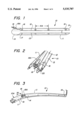
- FIG. 1 is a perspective drawing of the preferred embodiment of the present invention
- FIG. 2 is a perspective end view of the embodiment of FIG. 1;
- FIG. 3 is a perspective drawing of two cable holders connected end to end;
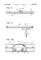
- FIG. 4 is a side elevation drawing of two cable holders connected end to end;
- FIG. 5 is a plan view of a branch connection between two cable holders
- FIG. 5A is a detailed cross section of FIG. 5;
- FIG. 6 is a plan view of a ninety degree corner bend of the cable holder
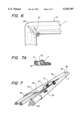
- FIG. 7 is a perspective drawing of a cable holder utilizing hook and loop fasteners
- FIG. 7A is a cross section of the embodiment of FIG. 7;
- FIG. 8 is a plan view of a cable holder application.
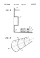
- FIG. 9 is a perspective drawing of a cable holder with transverse reinforcing ribs.
- FIG. 1 is a perspective drawing of the flexible cable holder 10.
- Web 11 is a flexible sheet having edge 12, opposite edge 13, end 14 and opposite end 15.
- web 11 is a woven nylon fabric impregnated with urethane for improved surface texture and moisture resistance.
- Web 11 may be made of a material to match floor or wall coverings.
- web 10 is impregnated with fire-retardant substances to improve fire safety.
- the web material, weave and impregnated material are chosen to allow sufficient flexibility for bending when the web is formed into a cable holder as described in the following sections.
- Releasable fasteners such as male snap fasteners 16 are disposed along edge 12.
- Matching releasable fasteners such as female snap fasteners 17 are disposed along opposite edge 13.
- the term matching fastener is one which engages the fastener.
- Fasteners 16 and matching fasteners 17 are spaced along the edges to provide adequate holder closure strength and edge coverage, normally 1"-12" between adjacent fasteners. In the preferred embodiment, the fastener spacing 16A is 6".
- a second set of releasable fasteners are used to connect end 14 and opposite end 15 to adjacent holders.
- Male end snap fastener 18 is attached to end flap 18A.
- End flap 18A is attached to end 14 of web 11 between edge fasteners 16 and matching edge fasteners 17.
- End flap 18A allows fastener 18 to extend outward beyond end 14 to fasten adjacent webs as shown in FIG. 3.
- Female end snap fastener 19 is attached to end 15 between edge fasteners 16 and matching edge fasteners 17.
- Fasteners and matching fasteners are attached to web 11 or end flap 18A by crimping, sewing, bonding or other suitable means.
- FIG. 2 is an end perspective view of cable holder 10.
- Web 11 is wrapped around cables 20 to form the holder.
- Edge fasteners 16 and matching edge fasteners 17 (not shown) fasten edge 12 and opposite edge 13 to secure holder 10.
- End fastener 18 of end flap 18A attaches holder 10 to an adjacent holder.
- FIG. 3 shows holder 10 attached to an adjacent holder 10A.
- End fastener 18 of end flap 18A fastens holder 10 to matching end fastener 19 of holder 10A.
- End fastener 18 extends beyond end 14 of holder 10 by a sufficient distance 30 to enable end fastener 18 to engage matching end fastener 19 of adjacent holder 10A without crimping or folding web 11.
- End fastener 18 is attached to holder 10 in the required position by end flap 18A. Additional end flaps 18A and end fasteners 18 and 19 may be added for additional security to the connection between holders.
- FIG. 4 is a side elevation view of end fastener 18 of holder 10 engaging matching end fastener 19 of adjacent holder 10A.
- FIG. 5 is a plan view of holder 10 making branch connection 50 with holder 10A. Edge fastener 16 of holder 10A engages matching end fastener 19 (Shown in FIG. 5A) of holder 10 to secure the holders together.
- Branch connection 50 may be a "T" or "Y” connection as required.
- FIG. 5A is a cross section detail of FIG. 5 showing edge fastener 16 of holder 10A engaging matching end fastener 19 of holder 10. Edge 12 and opposite edge 13 are separated as shown in FIG. 5A to insert end 15 of holder 10 in holder 10A to form the branch connection. Matching edge fastener 17A of separated edge 13 is not used when the branch connection is made. Cable 20 may be routed from holder 10A to holder 10 as shown in the figure.
- FIG. 6 is a plan view of cable holder 10 making a 90 degree corner 60.
- the inside of corner 60 will form ridges 61 due to the flexibility of web 11.
- Use of flexible web 11 in holder 10 allows turns without the need for special fittings.
- FIG. 7 is a perspective drawing of alternative embodiment 70 utilizing hook and loop fasteners.
- Edge fastener 71 engages matching edge fastener 72 to form holder 70.
- End fastener 73 located on the inside surface 77 of end 75 engages matching end fastener 74 on the outside surface 78 of opposite end 76 of an adjacent holder (not shown) to join adjacent holders.
- the ends of adjacent holders are overlapped (not shown) as necessary to engage the end fasteners.
- Fasteners are attached to web 11 by adhesive bonding or sewing.
- FIG. 7A is a cross section of holder 70 showing edge fastener 71 engaging matching edge fastener 72 to enclose holder 70.
- FIG. 8 is a plan view of multiple sections of holder 10 installed in a computer workstation environment. Individual cables 20 may be routed from holders 10 to components 80, or they may be branched at branch connections 50. Cable holders are flexible enough to make corners 60 without special fittings.
- FIG. 9 shows alternative embodiment 90 utilizing reinforcing ribs 91 to add rigidity to the holder without significantly reducing the ability to form corners and bends in the holder.
- Rib 91 is disposed transversely to longitudinal axis 92 of holder 90.
- Ribs 91 may be of rubber, plastic or other suitable material. They may be bonded, sewn or molded integrally with an impregnated material of web 11.
- the standard holder length is 6' and the standard web width is 10"-12". Other lengths and widths can be used as desired or convenient. A section may be cut to allow termination at the desired point. If greater cable volume is required, sections may be joined edge to opposite edge. The inherent design of the cable holder allows great flexibility in applications without special fittings, adaptors or add ons.
- the Flexible Cable Holder provides a practical conduit for routing cords and cables.
- the cable holder comprises the following additional advantages:
- sections may be joined edge to opposite edge to increase capacity
- end fasteners may be connected to edge fasteners to form branch connections
- button and button hole fasteners can be used to fasten edges and ends, and reinforcing strips may be added to prevent fraying when a section is cut, etc.
Abstract
A flexible cable holder is disclosed comprising a flexible web with a plurality of edge fasteners along opposite edges of the web. The edge fasteners are engaged, forming an enclosed duct for retaining cables, wires and power cords. End fasteners are provided at the ends of the web for attaching adjacent cable holders end-to-end. The web is flexible allowing the cable holder to form bends without special fittings or devices. End fasteners may be connected to edge fasteners to form branch connections.
Description
As technology of digital processing and communication continues to improve, more and more of these devices are used in homes and offices. New accessories and peripheral devices are available and finding use in ever increasing numbers. These devices include computers, printers, monitors, modems, switches, remote storage devices, FAX machines, speakers and other devices. The increased use of these devices frequently results in problems containing, routing, protecting and concealing cables, power cords and wiring between the devices. This is especially a problem as more of these devices are networked between workstations and other servers. Frequently, the connection of these devices leads to an unsightly arrangement, at best, and a potential safety problem, in other cases.
Cable raceways or ducts have been used for some time to route cables and power cords. Examples of these devices include U.S. Pat. No. 1,794,102 for a conduit for electric wires and U.S. Pat. No. 5,235,136 for a one piece recloseable cable and wire duct. These and other devices suffer the drawbacks of requiring special fittings or devices at corners, turns or branch connections. They are also time consuming to install in corners and at branch connections and are difficult to conceal when mounted along floors, walls or along the edge of furniture.
The present invention provides a device which addresses the disadvantages of earlier cable retaining devices. An object of the present invention is to provide a cable holder which retains one or more cables, power cords, wires or optical fiber devices along floors, walls or furniture.
Another object of the present invention is to provide a cable holder which can easily be connected end-to-end without separate fittings.
Another object of the present invention is to provide a cable holder which does not require special fittings or parts for turns or branch connections.
Another object of the present invention is to provide a cable holder which can be quickly and easily installed without special tools or installation experience.
Another object of the present invention is to provide a cable holder of a material which can be concealed.
Another object of the present invention is to provide a cable holder which is very inexpensive to purchase and install.
Yet another object of the present invention is to provide a cable holder for easy addition, removal or re-routing of a cable.
Still another object of the present invention is to provide a cable holder which can be removed and reused in another installation.
The present invention is a cable holder which comprises a flexible web having releasable fasteners along the edges of the web. The web is wrapped around the cable or cables and the edge fasteners are engaged, enclosing the cables. The web comprises an end fastener located on one end between the edge fasteners to fasten adjacent cable holders end-to-end. The flexible web allows the holder to flex around or inside corners and make bends as required. The end fastener is fastened to an edge fastener to form branch connections.
The web of the preferred embodiment of the present invention is of a woven fabric to provide required flexibility and strength. The material can be made to match floor and wall coverings to conceal the holder. The fabric can be impregnated with moisture-resistant and fire-resistant materials.
Another embodiment of the present invention utilizes hook and loop fasteners for the edge and/or end fasteners. The edge fasteners may be continuous strips of fastener material or, in an alternative embodiment, the edge fasteners may be a plurality of fasteners spaced along the edge of the holder. Reinforcing ribs, transverse to the longitudinal axis can be attached to the web to provide a desired cross sectional shape to the holder without significantly reducing the bending flexibility of the cable holder.
These and other features, aspects and advantages of the present invention will become better understood with regard to the following description, appended claims and accompanying drawings where:
FIG. 1 is a perspective drawing of the preferred embodiment of the present invention;
FIG. 2 is a perspective end view of the embodiment of FIG. 1;
FIG. 3 is a perspective drawing of two cable holders connected end to end;
FIG. 4 is a side elevation drawing of two cable holders connected end to end;
FIG. 5 is a plan view of a branch connection between two cable holders;
FIG. 5A is a detailed cross section of FIG. 5;
FIG. 6 is a plan view of a ninety degree corner bend of the cable holder;
FIG. 7 is a perspective drawing of a cable holder utilizing hook and loop fasteners;
FIG. 7A is a cross section of the embodiment of FIG. 7;
FIG. 8 is a plan view of a cable holder application; and
FIG. 9 is a perspective drawing of a cable holder with transverse reinforcing ribs.
The following is a detailed description of a flexible cable holder which conceals a collection of cables.
FIG. 1 is a perspective drawing of the flexible cable holder 10. Web 11 is a flexible sheet having edge 12, opposite edge 13, end 14 and opposite end 15. In the preferred embodiment, web 11 is a woven nylon fabric impregnated with urethane for improved surface texture and moisture resistance. Web 11 may be made of a material to match floor or wall coverings. In an alternative embodiment, web 10 is impregnated with fire-retardant substances to improve fire safety. The web material, weave and impregnated material are chosen to allow sufficient flexibility for bending when the web is formed into a cable holder as described in the following sections.
Releasable fasteners such as male snap fasteners 16 are disposed along edge 12. Matching releasable fasteners such as female snap fasteners 17 are disposed along opposite edge 13. (Within the context of the attached specification and claims, the term matching fastener is one which engages the fastener.) Fasteners 16 and matching fasteners 17 are spaced along the edges to provide adequate holder closure strength and edge coverage, normally 1"-12" between adjacent fasteners. In the preferred embodiment, the fastener spacing 16A is 6".
A second set of releasable fasteners are used to connect end 14 and opposite end 15 to adjacent holders. Male end snap fastener 18 is attached to end flap 18A. End flap 18A is attached to end 14 of web 11 between edge fasteners 16 and matching edge fasteners 17. End flap 18A allows fastener 18 to extend outward beyond end 14 to fasten adjacent webs as shown in FIG. 3. Female end snap fastener 19 is attached to end 15 between edge fasteners 16 and matching edge fasteners 17. Fasteners and matching fasteners are attached to web 11 or end flap 18A by crimping, sewing, bonding or other suitable means.
FIG. 2 is an end perspective view of cable holder 10. Web 11 is wrapped around cables 20 to form the holder. Edge fasteners 16 and matching edge fasteners 17 (not shown) fasten edge 12 and opposite edge 13 to secure holder 10. End fastener 18 of end flap 18A attaches holder 10 to an adjacent holder.
FIG. 3 shows holder 10 attached to an adjacent holder 10A. End fastener 18 of end flap 18A fastens holder 10 to matching end fastener 19 of holder 10A. End fastener 18 extends beyond end 14 of holder 10 by a sufficient distance 30 to enable end fastener 18 to engage matching end fastener 19 of adjacent holder 10A without crimping or folding web 11. End fastener 18 is attached to holder 10 in the required position by end flap 18A. Additional end flaps 18A and end fasteners 18 and 19 may be added for additional security to the connection between holders.
FIG. 4 is a side elevation view of end fastener 18 of holder 10 engaging matching end fastener 19 of adjacent holder 10A.
FIG. 5 is a plan view of holder 10 making branch connection 50 with holder 10A. Edge fastener 16 of holder 10A engages matching end fastener 19 (Shown in FIG. 5A) of holder 10 to secure the holders together. Branch connection 50 may be a "T" or "Y" connection as required.
FIG. 5A is a cross section detail of FIG. 5 showing edge fastener 16 of holder 10A engaging matching end fastener 19 of holder 10. Edge 12 and opposite edge 13 are separated as shown in FIG. 5A to insert end 15 of holder 10 in holder 10A to form the branch connection. Matching edge fastener 17A of separated edge 13 is not used when the branch connection is made. Cable 20 may be routed from holder 10A to holder 10 as shown in the figure.
FIG. 6 is a plan view of cable holder 10 making a 90 degree corner 60. The inside of corner 60 will form ridges 61 due to the flexibility of web 11. Use of flexible web 11 in holder 10 allows turns without the need for special fittings.
FIG. 7 is a perspective drawing of alternative embodiment 70 utilizing hook and loop fasteners. Edge fastener 71 engages matching edge fastener 72 to form holder 70. End fastener 73 located on the inside surface 77 of end 75 engages matching end fastener 74 on the outside surface 78 of opposite end 76 of an adjacent holder (not shown) to join adjacent holders. The ends of adjacent holders are overlapped (not shown) as necessary to engage the end fasteners. Fasteners are attached to web 11 by adhesive bonding or sewing.
FIG. 7A is a cross section of holder 70 showing edge fastener 71 engaging matching edge fastener 72 to enclose holder 70.
FIG. 8 is a plan view of multiple sections of holder 10 installed in a computer workstation environment. Individual cables 20 may be routed from holders 10 to components 80, or they may be branched at branch connections 50. Cable holders are flexible enough to make corners 60 without special fittings.
FIG. 9 shows alternative embodiment 90 utilizing reinforcing ribs 91 to add rigidity to the holder without significantly reducing the ability to form corners and bends in the holder. Rib 91 is disposed transversely to longitudinal axis 92 of holder 90. Ribs 91 may be of rubber, plastic or other suitable material. They may be bonded, sewn or molded integrally with an impregnated material of web 11.
In the preferred embodiment, the standard holder length is 6' and the standard web width is 10"-12". Other lengths and widths can be used as desired or convenient. A section may be cut to allow termination at the desired point. If greater cable volume is required, sections may be joined edge to opposite edge. The inherent design of the cable holder allows great flexibility in applications without special fittings, adaptors or add ons.
Accordingly the reader will see the Flexible Cable Holder provides a practical conduit for routing cords and cables. The cable holder comprises the following additional advantages:
it is flexible enough to make turns and bends without special fittings;
it can be made to match the floor or wall coverings;
sections may be joined edge to opposite edge to increase capacity;
end fasteners may be connected to edge fasteners to form branch connections;
It can be installed quickly and easily by a user with no special tools or experience; and
it is simple and can be manufactured at low cost.
Although the description above contains many specifications, these should not be construed as limiting the scope of the invention but as merely providing illustrations of some of the presently preferred embodiments of this invention. For example, button and button hole fasteners can be used to fasten edges and ends, and reinforcing strips may be added to prevent fraying when a section is cut, etc.
Thus the scope of the invention should be determined by the appended claims and their legal equivalents, rather than by the examples given.
Claims (3)
1. A flexible cable holder for retaining cables comprising:
(a) a flexible web having an edge, an opposite edge, an end, an opposite end, an inside surface and an outside surface;
(b) a releasable edge fastener disposed on the inside surface of the web along the edge;
(c) a matching releasable edge fastener disposed on the outside surface of the web along the opposite edge;
(d) a releasable end fastener disposed near the end of the web on the inside surface between the edge fastener and the matching edge fastener, the releasable end fastener spaced from the end of the web by a first separation distance; and
(e) a matching releasable end fastener disposed near the opposite end of the web on the outside surface between the edge fastener and the matching edge fastener, the matching releasable end fastener spaced from the opposite end of the web by a second separation distance;
wherein the web is constructed of a material of flexibility sufficient to allow bending of the web around a corner when the web is wrapped around a cable and the edge fastener engaged to the matching edge fastener to enclose the cable in the web, and
wherein the releasable end fastener and the matching releasable end fastener provide a means for attaching a plurality of said cable holders end to end with an end of a first said cable holder overlapping an opposite end of a second said cable holder.
2. The holder of claim 1 wherein the edge fastener and the end fastener are hook and loop fasteners and the matching edge fastener and matching end fasteners are matching hook and loop fasteners.
3. The holder of claim 1 wherein the edge fastener and the end fastener are snap fasteners and the matching edge fastener and matching end fastener are matching snap fasteners.
Priority Applications (3)
| Application Number | Priority Date | Filing Date | Title |
|---|---|---|---|
| US08/349,666 US5535787A (en) | 1994-12-02 | 1994-12-02 | Flexible cable holder |
| AU43701/96A AU4370196A (en) | 1994-12-02 | 1995-11-28 | Flexible cable holder |
| PCT/US1995/015405 WO1996017197A1 (en) | 1994-12-02 | 1995-11-28 | Flexible cable holder |
Applications Claiming Priority (1)
| Application Number | Priority Date | Filing Date | Title |
|---|---|---|---|
| US08/349,666 US5535787A (en) | 1994-12-02 | 1994-12-02 | Flexible cable holder |
Publications (1)
| Publication Number | Publication Date |
|---|---|
| US5535787A true US5535787A (en) | 1996-07-16 |
Family
ID=23373436
Family Applications (1)
| Application Number | Title | Priority Date | Filing Date |
|---|---|---|---|
| US08/349,666 Expired - Fee Related US5535787A (en) | 1994-12-02 | 1994-12-02 | Flexible cable holder |
Country Status (3)
| Country | Link |
|---|---|
| US (1) | US5535787A (en) |
| AU (1) | AU4370196A (en) |
| WO (1) | WO1996017197A1 (en) |
Cited By (55)
| Publication number | Priority date | Publication date | Assignee | Title |
|---|---|---|---|---|
| DE19746526A1 (en) * | 1997-10-22 | 1999-04-29 | Volkswagen Ag | Vehicle wiring loom |
| US5901756A (en) * | 1997-09-03 | 1999-05-11 | Goodrich; John J. | Flexible wear sleeve |
| US5943963A (en) * | 1997-10-10 | 1999-08-31 | Ireco Incorporated | Combination lading tie-down strap and protective shield therefor |
| US5967194A (en) * | 1998-01-23 | 1999-10-19 | Federal-Mogul Systems Protection Group, Inc. | Self-sealing tubing |
| US6006934A (en) * | 1998-02-05 | 1999-12-28 | Skrysak; Carol | Collapsible storage device |
| US6102076A (en) * | 1999-09-27 | 2000-08-15 | Romero, Jr.; Frank A. | Exhaust pipe cover |
| US6327159B1 (en) * | 1999-04-29 | 2001-12-04 | Hewlett-Packard Company | Wireform bracket for managing computer cables |
| US6378812B1 (en) * | 2000-08-30 | 2002-04-30 | Alderon Industries, Llc | Cable attachment method and device |
| US20030034583A1 (en) * | 2000-03-14 | 2003-02-20 | Velcro Industries B.V. | Stretchable fastener |
| EP1338017A1 (en) * | 2000-10-11 | 2003-08-27 | Motorola, Inc. | Cable management apparatus and method |
| US6655643B1 (en) * | 2001-03-30 | 2003-12-02 | Cisco Technology, Inc. | Flex circuit cabling wallet |
| US20030232163A1 (en) * | 2002-06-17 | 2003-12-18 | Graham Craig Jay | Wire loom |
| US20040058121A1 (en) * | 2002-09-13 | 2004-03-25 | Ideative Product Ventures, Inc. | Flexible bundling and labeling device |
| WO2004066464A1 (en) * | 2003-01-22 | 2004-08-05 | Georg-Simon-Ohm-Fachhochschule Nürnberg | Extensible and suspendable cable conduit comprising at least one cable conduit element |
| US20040255435A1 (en) * | 2003-06-18 | 2004-12-23 | Suburban Machine Co., Inc. Dba Suburban Manufacturing, Inc. | Reusable hose bundling sleeve |
| CN1309132C (en) * | 2002-05-31 | 2007-04-04 | 费德罗-莫格尔动力系公司 | Thin sheath with ripple and twisting part and its producing device and method |
| US20070181751A1 (en) * | 2006-02-08 | 2007-08-09 | Newkirk David C | Line management device |
| US20070261246A1 (en) * | 2004-10-05 | 2007-11-15 | Gerd Kasselmann | Cutting and Transport Device for Webs of Material |
| EP1859455A2 (en) * | 2005-03-14 | 2007-11-28 | Federal-Mogul Corporation | Protective sheath with integral biased flap closure |
| US7325575B1 (en) | 2004-03-15 | 2008-02-05 | Trach-Mate Incorporated | Rope and webbing protector |
| US20080104804A1 (en) * | 2003-06-18 | 2008-05-08 | Suburban Machine Co., Inc. Dba Suburban Manufacturing, Inc. | Reusable hose bundling sleeve |
| US20080121425A1 (en) * | 2006-11-27 | 2008-05-29 | Mitsuhiro Harada | Closed type cable or the like protection and guide device |
| US20080156529A1 (en) * | 2006-08-18 | 2008-07-03 | Airbus France | Attachment system for cables and support for cables used in aeronautic construction |
| US20090127296A1 (en) * | 2007-11-15 | 2009-05-21 | Parker Joshua B | Bulk bag to hopper shielding apparatus |
| US20100126768A1 (en) * | 2007-05-22 | 2010-05-27 | Panduit Corp. | Sealing Assembly |
| US20100159741A1 (en) * | 2008-12-18 | 2010-06-24 | Wayne Philip Rothbaum | Magnetic Cord Management System |
| US20110192857A1 (en) * | 2008-12-18 | 2011-08-11 | Wayne Philip Rothbaum | Magnetically Attached Accessories (For A Case) for a Portable Electronics Device |
| US20110217507A1 (en) * | 2010-03-03 | 2011-09-08 | Kalkstein Harold M | Fishnet Hose Stocking a fastened tube for utility lines and hoses in aquatic/outdoor environments |
| CN102487185A (en) * | 2010-12-01 | 2012-06-06 | 河南省电力公司南阳供电公司 | Computer wire wiring channel |
| US8205314B1 (en) * | 2009-02-03 | 2012-06-26 | Dermody Iv William E | Reversible cable covering for use in chroma key videography |
| US20120187271A1 (en) * | 2011-01-21 | 2012-07-26 | Tsubakimoto Chain Co. | Articulated cable protection and guide device |
| US20120261156A1 (en) * | 2011-04-12 | 2012-10-18 | 3M Innovative Properties Company | Protection device for a cable connection |
| US20130037156A1 (en) * | 2010-04-09 | 2013-02-14 | Peter Andrew John May | Hose shroud |
| GB2498744A (en) * | 2012-01-25 | 2013-07-31 | Perry Coppen | Cable tidy |
| US20130319566A1 (en) * | 2012-05-30 | 2013-12-05 | David Donald PETTY | Extendable Rope Protecting Sleeve |
| US8615849B2 (en) | 2010-04-14 | 2013-12-31 | Cjd Llc | Cord management system |
| US8640997B1 (en) * | 2010-09-28 | 2014-02-04 | Robert Caskey | Sensor harness clamp for continuous casting sensors |
| DE102012015546A1 (en) * | 2012-08-08 | 2014-02-13 | Horst Meyer | umbilical cord |
| US20140374308A1 (en) * | 2013-06-24 | 2014-12-25 | Samsung Medison Co., Ltd. | Cable packaging for medical devices |
| USD762588S1 (en) | 2014-04-10 | 2016-08-02 | Peter Chin | Cable management device |
| US20160279477A1 (en) * | 2015-03-25 | 2016-09-29 | David Donald PETTY | Extendable Rope Protecting Sheath |
| US9769943B2 (en) | 2013-08-09 | 2017-09-19 | Peter Chin | Cable management device |
| US20180169933A1 (en) * | 2016-12-16 | 2018-06-21 | The Zippertubing Co. | Wrap-around breakout jacket |
| US10092151B2 (en) * | 2016-09-15 | 2018-10-09 | F2M International Inc. | Vacuum hose cover |
| US10105482B1 (en) | 2016-11-01 | 2018-10-23 | Laina M. Holland | Enveloping assembly and method for sterilized and static resistant ordering of medical wires and tubes |
| US10213649B2 (en) | 2016-09-16 | 2019-02-26 | Peak Performance Leadership, LLC | Climbing rope protector device and method of using same |
| CN110350366A (en) * | 2018-04-04 | 2019-10-18 | 矢崎总业株式会社 | The branching method of branch circuit body and electric wire |
| USD871349S1 (en) * | 2013-01-11 | 2019-12-31 | Harold Kalkstein | Utility sleeve |
| US10711921B2 (en) | 2015-03-13 | 2020-07-14 | Bradley D Barger | Reusable hose bundling sleeve |
| US10763653B2 (en) * | 2018-04-04 | 2020-09-01 | Yazaki Corporation | Branch circuit body and electric wire branching method |
| US10790650B2 (en) * | 2018-07-09 | 2020-09-29 | Icenine Industries, Llc | Conduit routing system |
| US11146050B2 (en) * | 2019-04-18 | 2021-10-12 | Illinois Tool Works Inc. | Apparatus, systems, and methods for increasing the lifespan of welding cable covers |
| US11219800B1 (en) * | 2020-10-21 | 2022-01-11 | Michael Ratigan | Rope edge protection system |
| US11384891B1 (en) * | 2021-02-27 | 2022-07-12 | John Stone | Hose protector device |
| US20220323671A1 (en) * | 2021-03-30 | 2022-10-13 | Carefusion 303, Inc. | Infusion line harness |
Families Citing this family (2)
| Publication number | Priority date | Publication date | Assignee | Title |
|---|---|---|---|---|
| GB9725306D0 (en) * | 1997-11-28 | 1998-01-28 | Cableship Ltd | Cable management system |
| DE10249470B3 (en) * | 2002-10-24 | 2004-05-13 | Daimlerchrysler Ag | Installation channel for reception of flexible electrical cables in automobile provided as hose formed from bent elastic foil with adhesive layer between overlapping hose arms |
Citations (21)
| Publication number | Priority date | Publication date | Assignee | Title |
|---|---|---|---|---|
| US1794102A (en) * | 1927-10-27 | 1931-02-24 | Arthur C Comins | Conduit for electric wires |
| US1933279A (en) * | 1931-10-06 | 1933-10-31 | Bundy Tubing Co | Tubing |
| US3161210A (en) * | 1961-06-19 | 1964-12-15 | Loof Nils Oskar Tore | Plastic strips |
| US3941159A (en) * | 1974-10-31 | 1976-03-02 | Wolcott Toll | Insulation assembly for a tubular conduit pipe |
| US4280258A (en) * | 1978-05-09 | 1981-07-28 | Siemens Aktiengesellschaft | Cable sleeve having a closable, longitudinal slit |
| US4374596A (en) * | 1978-06-30 | 1983-02-22 | Josef Schlemmer Gmbh | Pipe-form connector for cable ducts |
| US4391303A (en) * | 1979-05-03 | 1983-07-05 | Telefonaktiebolaget L M Ericsson | Band-shaped device for forming a pipe-shaped protection cover |
| US4532168A (en) * | 1983-05-25 | 1985-07-30 | Shaw Industries Limited | Heat shrinkable covering |
| US4576846A (en) * | 1983-09-06 | 1986-03-18 | Gert Noel | Flexible plastic foam with a groove- and tongue-like closing system |
| US4640032A (en) * | 1984-07-23 | 1987-02-03 | At&T Information Systems Inc. | Wire and cable organizing sleeve |
| US4669509A (en) * | 1986-05-30 | 1987-06-02 | Carol Botsolas | Pipe insulation fitting cover and fastening means and methods of using the same |
| US4706914A (en) * | 1986-07-25 | 1987-11-17 | Minnesota Mining And Manufacturing Company | Attaching assembly |
| US4759963A (en) * | 1987-05-18 | 1988-07-26 | Uso Jr Madrid | Fishing pole fastening device |
| US4762750A (en) * | 1986-05-22 | 1988-08-09 | Ppg Industries, Inc. | Flexible, chemically treated bundles of fibers and process |
| US4862563A (en) * | 1987-07-13 | 1989-09-05 | Jane Marie Flynn | Securing strap and fastener |
| US4893381A (en) * | 1988-03-09 | 1990-01-16 | Frankel Eric H | Bundling strap with two adjustable closures |
| US4920235A (en) * | 1987-12-04 | 1990-04-24 | Kitagawa Industries Co., Ltd. | Conductive cable sheath |
| US5024251A (en) * | 1990-01-18 | 1991-06-18 | Square D Company | Lay-in wireway assembly |
| US5104076A (en) * | 1990-10-15 | 1992-04-14 | Goodall Jr James M | Article holder |
| US5235136A (en) * | 1991-07-24 | 1993-08-10 | Dek, Inc. | One-piece reclosable cable and wire duct |
| US5317787A (en) * | 1992-10-01 | 1994-06-07 | Thomas & Betts Corp. | Cable tie having improved tail gripping and holding feature |
Family Cites Families (1)
| Publication number | Priority date | Publication date | Assignee | Title |
|---|---|---|---|---|
| US4640039A (en) * | 1985-07-08 | 1987-02-03 | Neill John C O | Apparatus for retaining fishing rods in a boat |
-
1994
- 1994-12-02 US US08/349,666 patent/US5535787A/en not_active Expired - Fee Related
-
1995
- 1995-11-28 AU AU43701/96A patent/AU4370196A/en not_active Abandoned
- 1995-11-28 WO PCT/US1995/015405 patent/WO1996017197A1/en active Application Filing
Patent Citations (22)
| Publication number | Priority date | Publication date | Assignee | Title |
|---|---|---|---|---|
| US1794102A (en) * | 1927-10-27 | 1931-02-24 | Arthur C Comins | Conduit for electric wires |
| US1933279A (en) * | 1931-10-06 | 1933-10-31 | Bundy Tubing Co | Tubing |
| US3161210A (en) * | 1961-06-19 | 1964-12-15 | Loof Nils Oskar Tore | Plastic strips |
| US3941159A (en) * | 1974-10-31 | 1976-03-02 | Wolcott Toll | Insulation assembly for a tubular conduit pipe |
| US4280258A (en) * | 1978-05-09 | 1981-07-28 | Siemens Aktiengesellschaft | Cable sleeve having a closable, longitudinal slit |
| US4374596A (en) * | 1978-06-30 | 1983-02-22 | Josef Schlemmer Gmbh | Pipe-form connector for cable ducts |
| US4391303A (en) * | 1979-05-03 | 1983-07-05 | Telefonaktiebolaget L M Ericsson | Band-shaped device for forming a pipe-shaped protection cover |
| US4532168A (en) * | 1983-05-25 | 1985-07-30 | Shaw Industries Limited | Heat shrinkable covering |
| US4576846A (en) * | 1983-09-06 | 1986-03-18 | Gert Noel | Flexible plastic foam with a groove- and tongue-like closing system |
| US4640032A (en) * | 1984-07-23 | 1987-02-03 | At&T Information Systems Inc. | Wire and cable organizing sleeve |
| US4762750A (en) * | 1986-05-22 | 1988-08-09 | Ppg Industries, Inc. | Flexible, chemically treated bundles of fibers and process |
| US4669509A (en) * | 1986-05-30 | 1987-06-02 | Carol Botsolas | Pipe insulation fitting cover and fastening means and methods of using the same |
| US4706914A (en) * | 1986-07-25 | 1987-11-17 | Minnesota Mining And Manufacturing Company | Attaching assembly |
| US4759963A (en) * | 1987-05-18 | 1988-07-26 | Uso Jr Madrid | Fishing pole fastening device |
| US4862563A (en) * | 1987-07-13 | 1989-09-05 | Jane Marie Flynn | Securing strap and fastener |
| US4920235A (en) * | 1987-12-04 | 1990-04-24 | Kitagawa Industries Co., Ltd. | Conductive cable sheath |
| US4893381A (en) * | 1988-03-09 | 1990-01-16 | Frankel Eric H | Bundling strap with two adjustable closures |
| US5024251A (en) * | 1990-01-18 | 1991-06-18 | Square D Company | Lay-in wireway assembly |
| US5104076A (en) * | 1990-10-15 | 1992-04-14 | Goodall Jr James M | Article holder |
| US5235136A (en) * | 1991-07-24 | 1993-08-10 | Dek, Inc. | One-piece reclosable cable and wire duct |
| US5317787A (en) * | 1992-10-01 | 1994-06-07 | Thomas & Betts Corp. | Cable tie having improved tail gripping and holding feature |
| US5317787B1 (en) * | 1992-10-01 | 1995-11-28 | Thomas & Betts Corp | Cable tie having improved tail gripping and holding feature |
Cited By (78)
| Publication number | Priority date | Publication date | Assignee | Title |
|---|---|---|---|---|
| US5901756A (en) * | 1997-09-03 | 1999-05-11 | Goodrich; John J. | Flexible wear sleeve |
| US5943963A (en) * | 1997-10-10 | 1999-08-31 | Ireco Incorporated | Combination lading tie-down strap and protective shield therefor |
| DE19746526A1 (en) * | 1997-10-22 | 1999-04-29 | Volkswagen Ag | Vehicle wiring loom |
| US5967194A (en) * | 1998-01-23 | 1999-10-19 | Federal-Mogul Systems Protection Group, Inc. | Self-sealing tubing |
| US6006934A (en) * | 1998-02-05 | 1999-12-28 | Skrysak; Carol | Collapsible storage device |
| US6327159B1 (en) * | 1999-04-29 | 2001-12-04 | Hewlett-Packard Company | Wireform bracket for managing computer cables |
| US6102076A (en) * | 1999-09-27 | 2000-08-15 | Romero, Jr.; Frank A. | Exhaust pipe cover |
| US20030034583A1 (en) * | 2000-03-14 | 2003-02-20 | Velcro Industries B.V. | Stretchable fastener |
| US7223314B2 (en) | 2000-03-14 | 2007-05-29 | Velero Industries B.V. | Stretchable fastener |
| US6378812B1 (en) * | 2000-08-30 | 2002-04-30 | Alderon Industries, Llc | Cable attachment method and device |
| EP1338017A4 (en) * | 2000-10-11 | 2004-12-22 | Motorola Inc | Cable management apparatus and method |
| EP1338017A1 (en) * | 2000-10-11 | 2003-08-27 | Motorola, Inc. | Cable management apparatus and method |
| US6655643B1 (en) * | 2001-03-30 | 2003-12-02 | Cisco Technology, Inc. | Flex circuit cabling wallet |
| CN1309132C (en) * | 2002-05-31 | 2007-04-04 | 费德罗-莫格尔动力系公司 | Thin sheath with ripple and twisting part and its producing device and method |
| US20030232163A1 (en) * | 2002-06-17 | 2003-12-18 | Graham Craig Jay | Wire loom |
| US20040058121A1 (en) * | 2002-09-13 | 2004-03-25 | Ideative Product Ventures, Inc. | Flexible bundling and labeling device |
| WO2004066464A1 (en) * | 2003-01-22 | 2004-08-05 | Georg-Simon-Ohm-Fachhochschule Nürnberg | Extensible and suspendable cable conduit comprising at least one cable conduit element |
| US20040255435A1 (en) * | 2003-06-18 | 2004-12-23 | Suburban Machine Co., Inc. Dba Suburban Manufacturing, Inc. | Reusable hose bundling sleeve |
| US8127405B2 (en) | 2003-06-18 | 2012-03-06 | Suburban Machine Co., Inc. | Reusable hose bundling sleeve |
| US8691036B2 (en) | 2003-06-18 | 2014-04-08 | Suburban Machine Co., Inc. | Method of making a reusable hose bundling sleeve |
| US20080104804A1 (en) * | 2003-06-18 | 2008-05-08 | Suburban Machine Co., Inc. Dba Suburban Manufacturing, Inc. | Reusable hose bundling sleeve |
| US7325575B1 (en) | 2004-03-15 | 2008-02-05 | Trach-Mate Incorporated | Rope and webbing protector |
| US20070261246A1 (en) * | 2004-10-05 | 2007-11-15 | Gerd Kasselmann | Cutting and Transport Device for Webs of Material |
| EP1859455A2 (en) * | 2005-03-14 | 2007-11-28 | Federal-Mogul Corporation | Protective sheath with integral biased flap closure |
| EP1859455A4 (en) * | 2005-03-14 | 2011-11-16 | Federal Mogul Corp | Protective sheath with integral biased flap closure |
| US20100263123A1 (en) * | 2006-02-08 | 2010-10-21 | Newkirk David C | Line management device for a hospital bed |
| US20070181751A1 (en) * | 2006-02-08 | 2007-08-09 | Newkirk David C | Line management device |
| US8370977B2 (en) | 2006-02-08 | 2013-02-12 | Hill-Rom Services, Inc. | Line management device for a hospital bed |
| US7766289B2 (en) * | 2006-02-08 | 2010-08-03 | Hill-Rom Services, Inc. | Line management device |
| US7692104B2 (en) * | 2006-08-18 | 2010-04-06 | Airbus France | Attachment system for cables and support for cables used in aeronautic construction |
| US20080156529A1 (en) * | 2006-08-18 | 2008-07-03 | Airbus France | Attachment system for cables and support for cables used in aeronautic construction |
| US20080121425A1 (en) * | 2006-11-27 | 2008-05-29 | Mitsuhiro Harada | Closed type cable or the like protection and guide device |
| US7741563B2 (en) * | 2006-11-27 | 2010-06-22 | Tsubakimoto Chain Co. | Closed type cable or the like protection and guide device |
| US8183475B2 (en) * | 2007-05-22 | 2012-05-22 | Panduit Corp. | Sealing assembly |
| US20100126768A1 (en) * | 2007-05-22 | 2010-05-27 | Panduit Corp. | Sealing Assembly |
| US20090127296A1 (en) * | 2007-11-15 | 2009-05-21 | Parker Joshua B | Bulk bag to hopper shielding apparatus |
| US20110108304A1 (en) * | 2008-12-18 | 2011-05-12 | Wayne Philip Rothbaum | Magnetic Cord Management System |
| US20110192857A1 (en) * | 2008-12-18 | 2011-08-11 | Wayne Philip Rothbaum | Magnetically Attached Accessories (For A Case) for a Portable Electronics Device |
| US8841556B2 (en) | 2008-12-18 | 2014-09-23 | Cjd Llc | Magnetic cord management system |
| US20100159741A1 (en) * | 2008-12-18 | 2010-06-24 | Wayne Philip Rothbaum | Magnetic Cord Management System |
| US8205314B1 (en) * | 2009-02-03 | 2012-06-26 | Dermody Iv William E | Reversible cable covering for use in chroma key videography |
| US20110217507A1 (en) * | 2010-03-03 | 2011-09-08 | Kalkstein Harold M | Fishnet Hose Stocking a fastened tube for utility lines and hoses in aquatic/outdoor environments |
| US9052042B2 (en) * | 2010-04-09 | 2015-06-09 | Peter Andrew John May | Hose shroud |
| US20130037156A1 (en) * | 2010-04-09 | 2013-02-14 | Peter Andrew John May | Hose shroud |
| US8615849B2 (en) | 2010-04-14 | 2013-12-31 | Cjd Llc | Cord management system |
| US9445178B2 (en) | 2010-04-14 | 2016-09-13 | Cjd Llc | Cord management system |
| US8640997B1 (en) * | 2010-09-28 | 2014-02-04 | Robert Caskey | Sensor harness clamp for continuous casting sensors |
| CN102487185A (en) * | 2010-12-01 | 2012-06-06 | 河南省电力公司南阳供电公司 | Computer wire wiring channel |
| US20120187271A1 (en) * | 2011-01-21 | 2012-07-26 | Tsubakimoto Chain Co. | Articulated cable protection and guide device |
| US9368951B2 (en) * | 2011-01-21 | 2016-06-14 | Tsubakimoto Chain Co. | Articulated cable protection and guide device |
| US20120261156A1 (en) * | 2011-04-12 | 2012-10-18 | 3M Innovative Properties Company | Protection device for a cable connection |
| GB2498744A (en) * | 2012-01-25 | 2013-07-31 | Perry Coppen | Cable tidy |
| GB2498744B (en) * | 2012-01-25 | 2017-03-15 | Coppen Perry | Cable tidy |
| US8752590B2 (en) * | 2012-05-30 | 2014-06-17 | David Donald PETTY | Extendable rope protecting sleeve |
| US20130319566A1 (en) * | 2012-05-30 | 2013-12-05 | David Donald PETTY | Extendable Rope Protecting Sleeve |
| DE102012015546A1 (en) * | 2012-08-08 | 2014-02-13 | Horst Meyer | umbilical cord |
| USD871349S1 (en) * | 2013-01-11 | 2019-12-31 | Harold Kalkstein | Utility sleeve |
| US20140374308A1 (en) * | 2013-06-24 | 2014-12-25 | Samsung Medison Co., Ltd. | Cable packaging for medical devices |
| US9868557B2 (en) * | 2013-06-24 | 2018-01-16 | Samsung Medison Co., Ltd. | Cable packaging for medical devices |
| US9769943B2 (en) | 2013-08-09 | 2017-09-19 | Peter Chin | Cable management device |
| USD762588S1 (en) | 2014-04-10 | 2016-08-02 | Peter Chin | Cable management device |
| US10711921B2 (en) | 2015-03-13 | 2020-07-14 | Bradley D Barger | Reusable hose bundling sleeve |
| US9675843B2 (en) * | 2015-03-25 | 2017-06-13 | David Donald PETTY | Extendable rope protecting sheath |
| US20160279477A1 (en) * | 2015-03-25 | 2016-09-29 | David Donald PETTY | Extendable Rope Protecting Sheath |
| US10092151B2 (en) * | 2016-09-15 | 2018-10-09 | F2M International Inc. | Vacuum hose cover |
| US10213649B2 (en) | 2016-09-16 | 2019-02-26 | Peak Performance Leadership, LLC | Climbing rope protector device and method of using same |
| US10814173B2 (en) | 2016-09-16 | 2020-10-27 | Peak Perfomance Leadership, Llc | Climbing rope protector device and method of using same |
| US10105482B1 (en) | 2016-11-01 | 2018-10-23 | Laina M. Holland | Enveloping assembly and method for sterilized and static resistant ordering of medical wires and tubes |
| US20180169933A1 (en) * | 2016-12-16 | 2018-06-21 | The Zippertubing Co. | Wrap-around breakout jacket |
| US10886714B2 (en) * | 2018-04-04 | 2021-01-05 | Yazaki Corporation | Branching circuit body and branching method of electric wires |
| CN110350366A (en) * | 2018-04-04 | 2019-10-18 | 矢崎总业株式会社 | The branching method of branch circuit body and electric wire |
| US10763653B2 (en) * | 2018-04-04 | 2020-09-01 | Yazaki Corporation | Branch circuit body and electric wire branching method |
| US10790650B2 (en) * | 2018-07-09 | 2020-09-29 | Icenine Industries, Llc | Conduit routing system |
| US11146050B2 (en) * | 2019-04-18 | 2021-10-12 | Illinois Tool Works Inc. | Apparatus, systems, and methods for increasing the lifespan of welding cable covers |
| US11219800B1 (en) * | 2020-10-21 | 2022-01-11 | Michael Ratigan | Rope edge protection system |
| US11596838B1 (en) * | 2020-10-21 | 2023-03-07 | Michael Ratigan | Rope edge protection system |
| US11384891B1 (en) * | 2021-02-27 | 2022-07-12 | John Stone | Hose protector device |
| US20220323671A1 (en) * | 2021-03-30 | 2022-10-13 | Carefusion 303, Inc. | Infusion line harness |
Also Published As
| Publication number | Publication date |
|---|---|
| WO1996017197A1 (en) | 1996-06-06 |
| AU4370196A (en) | 1996-06-19 |
Similar Documents
| Publication | Publication Date | Title |
|---|---|---|
| US5535787A (en) | Flexible cable holder | |
| US4454374A (en) | Electric cord holder and cover | |
| US7049508B2 (en) | Flexible conduit | |
| US6751382B2 (en) | System for organizing wires and cables | |
| US6349904B1 (en) | Cable bundling and support device | |
| US4815172A (en) | Fastening device | |
| JP3863426B2 (en) | Conduit insert for optical fiber cable | |
| US4563542A (en) | Electric cord holder assembly | |
| US4829145A (en) | Corrugated plastic conduit system | |
| KR20160039266A (en) | Outer cover material for wire harness, and routing structure for wire harness | |
| US5300731A (en) | Conduit adapter assembly | |
| EP0630090A1 (en) | Device for joining trays for electrical conduits | |
| JPH0546607U (en) | Wire harness intermediate output device | |
| JP6984180B2 (en) | Wiring module laying structure and wiring module | |
| GB2137305A (en) | Duct system | |
| US5873553A (en) | Mounting bracket assembly for an outlet box | |
| US3095908A (en) | Combined jacket and suspension means for conductors and the like | |
| KR100381218B1 (en) | Cable Duct Assembly | |
| JP6992855B2 (en) | Wiring module | |
| KR200207493Y1 (en) | Corner connecting apparatus for distributing duct | |
| KR200214704Y1 (en) | A cable for duct | |
| KR200209922Y1 (en) | Cable Duct Assembly | |
| CN219035812U (en) | Inner corner fixing clamp and wiring assembly | |
| KR200382796Y1 (en) | Cable band | |
| CA1235410A (en) | Electric cord holder connecting element |
Legal Events
| Date | Code | Title | Description |
|---|---|---|---|
| REMI | Maintenance fee reminder mailed | ||
| FPAY | Fee payment |
Year of fee payment: 4 |
|
| SULP | Surcharge for late payment | ||
| REMI | Maintenance fee reminder mailed | ||
| LAPS | Lapse for failure to pay maintenance fees | ||
| FP | Lapsed due to failure to pay maintenance fee |
Effective date: 20040716 |
|
| STCH | Information on status: patent discontinuation |
Free format text: PATENT EXPIRED DUE TO NONPAYMENT OF MAINTENANCE FEES UNDER 37 CFR 1.362 |