US5530484A - Image scanning format converter suitable for a high definition television system - Google Patents
Image scanning format converter suitable for a high definition television system Download PDFInfo
- Publication number
- US5530484A US5530484A US08/446,125 US44612595A US5530484A US 5530484 A US5530484 A US 5530484A US 44612595 A US44612595 A US 44612595A US 5530484 A US5530484 A US 5530484A
- Authority
- US
- United States
- Prior art keywords
- format
- signal
- output
- input
- progressive
- Prior art date
- Legal status (The legal status is an assumption and is not a legal conclusion. Google has not performed a legal analysis and makes no representation as to the accuracy of the status listed.)
- Expired - Lifetime
Links
Images


Classifications
-
- H—ELECTRICITY
- H04—ELECTRIC COMMUNICATION TECHNIQUE
- H04N—PICTORIAL COMMUNICATION, e.g. TELEVISION
- H04N7/00—Television systems
- H04N7/01—Conversion of standards, e.g. involving analogue television standards or digital television standards processed at pixel level
- H04N7/0117—Conversion of standards, e.g. involving analogue television standards or digital television standards processed at pixel level involving conversion of the spatial resolution of the incoming video signal
- H04N7/012—Conversion between an interlaced and a progressive signal
-
- H—ELECTRICITY
- H04—ELECTRIC COMMUNICATION TECHNIQUE
- H04N—PICTORIAL COMMUNICATION, e.g. TELEVISION
- H04N7/00—Television systems
- H04N7/01—Conversion of standards, e.g. involving analogue television standards or digital television standards processed at pixel level
-
- H—ELECTRICITY
- H04—ELECTRIC COMMUNICATION TECHNIQUE
- H04N—PICTORIAL COMMUNICATION, e.g. TELEVISION
- H04N21/00—Selective content distribution, e.g. interactive television or video on demand [VOD]
- H04N21/40—Client devices specifically adapted for the reception of or interaction with content, e.g. set-top-box [STB]; Operations thereof
- H04N21/41—Structure of client; Structure of client peripherals
- H04N21/426—Internal components of the client ; Characteristics thereof
-
- H—ELECTRICITY
- H04—ELECTRIC COMMUNICATION TECHNIQUE
- H04N—PICTORIAL COMMUNICATION, e.g. TELEVISION
- H04N5/00—Details of television systems
- H04N5/44—Receiver circuitry for the reception of television signals according to analogue transmission standards
- H04N5/46—Receiver circuitry for the reception of television signals according to analogue transmission standards for receiving on more than one standard at will
Definitions
- This invention is related to the field of digital image signal processing.
- this invention concerns a line scan converter system suitable for use with a high definition image signal processing such as the high definition television system proposed for use in the United States.
- HDTV digital high definition television
- An HDTV terrestrial broadcast system recently proposed as the Grand Alliance HDTV system in the United States employs a vestigial sideband (VSB) transmission format for transmitting a packetized datastream.
- the Grand Alliance HDTV system is a proposed transmission standard that is under consideration in the United States by the Federal Communications Commission (FCC) through its Advisory Committee of Advanced Television Service (ACATS).
- FCC Federal Communications Commission
- ACATS Advisory Committee of Advanced Television Service
- the Grand Alliance HDTV system supports image information in two raster line scanning formats.
- One format is a 2:1 line interlaced format with a 30 Hz frame rate.
- the other is a 1:1 non-interlaced, or progressive (line sequential) format with a 60 Hz frame rate.
- the interlaced image display exhibits the following characteristics:
- Source material to be transmitted to a television receiver may exhibit either format.
- a broadcast television program from one source may be in progressive form while one or more commercials or other intervening material from other sources may be in interlaced form.
- an adaptive scan format converter at a transmitter as a function of what format is desired for coding and transmission via an output channel.
- a receiver it is recognized as desirable to automatically convert a received scan format to a desired format for display by an associated image display device.
- a received interlaced signal will be automatically converted to progressive form if necessary to be compatible with a progressive scan display device, and a received progressive signal will be passed to the display device without format conversion.
- automatic scan conversion is performed seamlessly so that, for example, conversion between progressive main program material and interlaced commercial material, or vice-versa, is produced without artifacts and is essentially invisible to a viewer.
- FIG. 1 is a block diagram of a transmitter and receiver television system in which the invention may be employed.
- FIG. 2 shows details of a scan format converter system in accordance with the principles of the present invention.
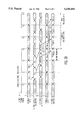
- FIGS. 3A and 3B illustrate signal waveforms helpful in understanding the operation of the system shown in FIG. 2.
- FIG. 4 shows a portion of the system of FIG. 2 in greater detail.
- a source 10 of interlaced video signal "I" and a source 12 of progressive video signal "P" in a broadcast television encoder/transmitter provide output video signals to respective inputs of an automatic scan format converter 14 which operates in accordance with the principles of the present invention.
- Scan converter 14 will be shown and described in greater detail with regard to FIG. 2.
- the television system is an HDTV system of the type proposed by the Grand Alliance in the United States as noted above.
- Video sources 10 and 12 are mutually synchronized ("genlocked"). In this example only one of these sources is active at a time, although in some systems both may be active. In the case where only one of the signal sources is active at a time, converter automatically selects the input port with the active video signal. If the scanning format of the active video signal is the same as the format desired for a transmitted video signal, the scanning format of the input video signal is not altered by converter 14. If the input format is different, converter 14 automatically converts the format of the input video signal so as to be compatible with the desired output signal format.
- the output signal from scan converter 14 is data compressed by an MPEG encoder 16, as known, before being applied to a transport processor 18.
- Processor 18 formats compressed data from encoder 16 into data packets, prefaces the data packets with header information which identifies the contents of the respective packets, and adds synchronizing and other information, for example.
- Data packets from transport processor 18 are processed for transmission via a transmission channel 25 by a transmission processor 20.
- Processor 20 includes data formatting, error coding, buffering, digital to analog converter and RF (radio frequency) modulating networks for conditioning the video signal for transmission via channel 25.
- the signal from channel 25 is first processed by a unit 30 including RF tuning and filtering networks, IF (intermediate frequency) networks, demodulation and error processing networks, and an analog to digital converter, for example.
- An output signal from unit 30 is processed by a unit 32 which performs the inverse of the operation of unit 18 at the transmitter. Specifically, unit 32 evaluates header information for identifying the constituent data packet components and separates these components (e.g., video, audio and synchronization information) for processing by respective circuits.
- the data components from decoder 32 are decompressed by an MPEG decoder 34 as known.
- MPEG decoder 34 includes an interlaced video signal output port at which a transmitted 1080 line interlaced video signal would appear, and a progressive video signal output port at which a transmitted 720 line progressive video signal would appear. MPEG decoder 34 also includes provision for deriving coded information from the received data stream indicating whether a received video signal exhibits interlaced or progressive form.
- a television receiver includes an associated display device which may be an interlaced scan type or a progressive scan type. These possibilities are illustrated by means of an interlaced display device 38 and a progressive display device 39. A practical receiver will have one but not both of such display devices.
- the receiver display device receives a signal to be displayed from a format converter 36 (after processing by appropriate signal conditioning and display driver circuits not shown to simplify the drawing).
- Format converter 36 is programmed with information (e.g., by the receiver manufacturer or via a locally generated control signal) to indicate the type of the associated display, i.e., interlaced or progressive, since in this example it is assumed that an associated display device is able to display video information in only one scanning format. Accordingly, format converter 36 is arranged to automatically provide an output signal in a format compatible with the display device, regardless of which of the two video signal formats is received and decoded.
- converter 36 will bypass a received interlaced video signal from unit 34 to the output of converter 36 without modifying its scan format. If a received video signal is progressive, converter 36 will automatically sense this by sensing that the progressive outport of MPEG decoder 34 is active, convert such signal to interlaced form, and provide such signal at its interlaced signal output. Thus an interlaced video signal will always be provided to an interlaced display regardless of the scanning format of a transmitted video signal. Analogous observations pertain to a receiver with an associated progressive display such as device 39.
- FIG. 2 shows additional details of a scan format converter such as units 14 and 36 in FIG. 1.
- the converter of FIG. 2 corresponds to unit 36 in the receiver of FIG. 1.
- An input network 42 and an input network 44 respectively receive digital interlaced (I) and digital progressive (P) output signals from MPEG decoder 34.
- the input networks each include circuits for separating the video component and synchronizing components.
- the sync components include a horizontal sync component (H), a vertical sync component (V), a frame reference pulse (FRP) and a pixel clock CLK.
- the frequency of the pixel clock is derived from the product of the total number of pixels, the total number of lines, and the number of fields/second.
- Frame reference pulse FRP is a reference signal developed by MPEG decoder 34. It appears in a prescribed portion of the vertical blanking interval, and provides a reference point from which subsequent circuits count clocks to the first pixel of an interlaced field or a progressive frame.
- Converter 36 also includes an analog input for receiving analog R, G, B (or Y, U, V) color video components and associated horizontal and vertical synchronizing components H, V. These components may be generated by a video cassette recorder (VCR) or a video camera for example, and are converted to digital form by an analog to digital converter 48. Video outputs from units 42, 44 and 48 are applied to respective signal inputs of an input multiplexer (MUX) 46.
- VCR video cassette recorder
- MUX input multiplexer
- a synchronization and mode control unit 70 responds to digital sync components H and V, frame reference pulses FRP, and clocks CLK for both interlaced and progressive source signals, as well as to H and V sync components (H, V RGB) for the analog signal source after conversion to digital form by converter 48.
- a control input of network 70 receives an Output Format Control signal for determining the operating characteristics of the format converter as a function of whether an interlaced or progressive format is desired for an output video signal. This signal may be produced by a local switch setting, and determines whether the output video signal will be interlaced or progressive. This determination may be made by a broadcast operator at a transmitter, or by a receiver manufacturer.
- Output signals produced by network 70 include a frame reference pulse FRP(I) for interlaced signals, a frame reference pulse FRP(P) for progressive signals, a picture element (pixel) clock f s , a half-rate pixel clock 1/2 f s , and a Control signal.
- the Control signal is applied to an output multiplexer 60 for conveying either interlaced or a progressive video signal to an output, as will be discussed.
- Network 70 may include a phase locked loop (PLL) network frame and field locked by means of the FRP signals.
- PLL phase locked loop
- the pixel clock f s for an interlaced video signal is a 74.25 MHz signal (2200 pixels ⁇ 1125 lines total ⁇ 30 Hz field rate).
- Video information is transferred to the converter system via A/D unit 48 and input MUX 46, and from the converter system via D/A unit 62, at full pixel rate f s .
- the subsystems within the format converter operate in response to the 1/2 f s clock.
- Progressive to interlaced format conversion (720 lines to 540 lines) is accomplished by means of a P-I Conversion Path including input MUX 46, a horizontal and vertical pre-filter 54 which performs 4:3 decimation, an output MUX 60 and a digital to analog converter 62.
- Interlaced to progressive format conversion is accomplished by means of an I-P Conversion Path including MUX 46, a line doubling de-interlacer 50, a horizontal and vertical post-filter network 52 which performs 3:2 decimation, output MUX 60 and converter 62.
- Techniques for performing interpolation and decimation are well known.
- the video signal is conveyed via a Bypass Path including input MUX 46, output MUX 60 and digital to analog converter 62.
- frame Reference Pulses FRP and video information are respectively converted to analog sync components H, V and analog color video components R, G and B by means of converter 62. These components are then conveyed to synchronization and video signal processing and display driver circuits as known.
- Output port 64 is used only at a transmitter/encoder format encoder, e.g., unit 14 in FIG. 1, to convey digital information to MPEG coder 16.
- D/A converter 62 includes a Programmable Logic Network (as known) with a counter for generating the output H and V sync components.
- the FRP is applied to a reset input of the counter, and the Programmable Logic Network operates in response to clock f s and an output format select signal (derived from the Control signal) for producing the H and V output sync components after conversion to analog form.
- input MUX 46 receives a digital video signal, e.g., from units 42 or 48, at the pixel clock rate. MUX 46 then generates an output signal at one-half the input data rate. Specifically, pixel data arriving in a time sequence A, B, C, D, . . . are converted to a datastream of two pixels in parallel, e.g., A, B then C; D and so forth. This datastream is provided to an input of de-interlacing unit 50, which also receives a FRP sync component from unit 46. De-interlacing unit 50 operates as known by storing odd field lines 1, 3, 5, . . . and even field lines 2, 4, 6, .
- a video frame is generated by creating additional lines in every field so that an output signal from unit 50 represents a progressive video frame constituted by lines 1, 2, 3, 4, 5, 6, . . . and so forth.
- This de-interlacing operation could be as simple as repeating lines, or as elaborate as estimating motion in each field for each of the R, G, B color signal components and using the derived motion vectors to adjust coefficients in various directions to produce additional pixels, as known.
- unit 50 finds the greatest motion vector from among the three RGB color components. This vector is used by interpolation networks to generate new pixel values for the derived line.
- unit 50 generates an output signal with twice as many lines as the input signal, i.e., 1080 lines derived from the 540 lines in each field.
- Horizontal and vertical postfilter 52 subjects the output video signal from unit 50 to 3:2 decimation in the horizontal direction to generate 1280 output pixels from 1920 input pixels. In the vertical direction, filter 52 decimates the output signal from unit 50 by 3:2 to generate 720 output lines from 1080 input lines. This progressive signal is routed via MUX 60 and DAC 62 to subsequent signal processing and display circuits.
- an output signal from MUX 46 and the FRP component are applied to a horizontal and vertical pre-filter 54.
- Filter 54 subjects the video signal to 2:3 interpolation in the horizontal direction to generate 1920 output pixels from 1280 input pixels.
- filter 54 subjects the video signal to 2:3 decimation to generate 1080 output lines from 720 input lines.
- the interlaced output signal from unit 54 is routed via MUX 60 and DAC 62 to subsequent signal processing and display circuits.
- the FRP timing at the outputs of units 52 and 54 remains fixed.
- Output MUX 60 includes a frame memory (delay) network in the Bypass Path to compensate for signal processing delays associated with the P-I conversion path and the I-P conversion path. This frame delay also facilitates the seamless switching between video signals of different format. Switching occurs at frame boundaries. The frame delay allows the input video to switch randomly between the two formats and still provide an output signal in the desired format in a continuous stream without dropping any frames. If the format converter is arranged to provide. a progressive scan output, the input signal format can change between progressive and interlaced format without disrupting the signal data flow or losing video information in the output signal of the format converter.
- This feature allows, for example, a television commercial to be in progressive scan format while television main program material is in interlace scan format.
- Both types of video information when merged into a similar scan format using the seamless switching feature of the format converter, can be transmitted and received in real-time as one continuous stream of video information. This feature will be shown and discussed in connection with FIGS. 3 and 4.
- the format converter operates to convert the incoming progressive format to the desired output interlaced format.
- Pre-filter 54 in FIG. 2 exhibits a processing delay of slightly more than one frame duration for converting from progressive to interlaced format. The magnitude of this delay is not critical, but should be a known, fixed delay.
- mode control network 70 This can be accomplished by sensing a mode control signal from preceding circuits such as decoder 34 in FIG.
- the Control signal provided by network 70 to output MUX 60 indicates that this format change has occurred, causing output MUX 60 to begin storing the new interlaced input video signal that is conveyed directly from the output of input MUX 46 to output MUX 60 via the Bypass Path.
- MUX 60 stores this interlaced signal in a frame buffer memory.
- the frame buffer delay allows output MUX 60 to route the processed progressive video signal from filter 54 in its entirety to output DAC unit 62 for display, followed by the bypassed interlaced video from the frame buffer.
- Waveform A illustrates the position of Frame Reference Pulse FRP during the vertical blanking interval prior to the active video line scanning interval. The interval between each FRP is one image frame in this example.
- waveform (B) p in-0 and p in-1 represent input progressive video frames. These frames appear delayed at the output of pre-filter 54 (FIG. 2) as waveform (C) data hvpre-0 and hvpre-1. After conversion to interlaced format, these frames respectively appear as output interlaced video i out-0 and i out-1 shown in waveform (E).
- output video information i out-0 corresponds to input frame p in-0 .
- Output video information i out-1 corresponds to input progressive video p in-1 , and is the last progressive-to-interlace converted frame to appear before the input signal changes to interlaced format.
- output MUX 60 delays HVPRE filtered data by a few lines as will be explained in connection with FIG. 4.
- the output MUX delays the video information in the Bypass path by 2 frames, as will also be discussed in connection with FIG. 4.
- the input video signal changes to interlaced format at a time T 0 .
- These new interlaced frames are labeled i in-0 and i in-1 in waveform D.
- the interlaced video is subjected to a two frame delay associated with output MUX 60 as noted above, respectively resulting in i out-2 as shown in waveform E.
- the bypassed interlaced video appears at the output at time T1 and onward.
- interlaced data i out-2 which appears just after a time T1 at a frame boundary, is the first output data from the new interlaced input video signal. From time T1 onward, i.e., from the first line of the next image frame, the video lines continue seamlessly without interruption.
- an interlaced format is produced seamlessly from data i out-0 to data i out-2 etc. as the video input changes from progressive to interlaced format.
- the switch from a progressive format (waveform B) to interlaced format (waveform D) produces no visible artifacts and is unnoticed by a viewer.
- the format transition occurs a predetermined fixed amount of time (delay) after the appearance of the FRP to facilitate the seamless transition and avoid a discontinuity in a displayed image.
- FIG. 3B illustrates the seamless switching process in the case of providing a progressive video output signal format. This is accomplished in a manner analogous to that discussed with respect to FIG. 3A for an interlaced output signal format.
- FIG. 3B there are included a waveform C associated with the output of de-interlacer 50 in FIG. 2, and a waveform D associated with the output of HV Post filter 52 in the I-P path in the FIG. 2 system.
- Waveform D in FIG. 3B is analogous to waveform C in FIG. 3A.
- a delay of a few lines is indicated by (1) in FIG. 3B, and (2) indicates that the progressive video from the Bypass path is delayed by two frames by output MUX 60.
- converted progressive data appears in the interval T0-T1, while new progressive data commences at time T1.
- FIG. 4 shows details of output MUX 60.
- a multiplexer 80 receives an interlaced video input signal from a first FIFO buffer 82, a progressive video input signal from a second FIFO buffer 86, and either an interlaced or a progressive video signal from a frame buffer 84. Interlaced video signals are provided to buffer 82 from prefilter 54 (FIG. 2) in the P-I conversion path, input video signals are directly provided to frame buffer 84 from input MUX 46 (FIG. 2), and progressive video input signals are provided to buffer 86 from post filter 52 (FIG. 2) in the I-P conversion path.
- the size of buffers 82 and 86 is not critical, e.g., several video lines. Buffers 82 and 86 are used to compensate for the different signal delays associated with the three different input sources.
- Frame buffer 84 receives data directly from input MUX 60 in FIG. 2.
- Buffer 84 exhibits a two frame delay in this example. However, a one frame delay may be used in accordance with the requirements of other systems.
- Output signals from MUX 80 are conveyed to D/A converter 62 (FIG. 2) via latch 90.
- output MUX 60 in FIG. 2 receives three Frame Reference Pulses (FRP), one from each of filters 52 and 54 and another from input MUX 46. These pulses may be misaligned among each other by a few image lines. The clock-to-data timing may also be misaligned among the three sources. Therefore FIFO buffers are used to "clean up" any delay and timing misalignment before the seamless switching operation associated with MUX 80 in FIG. 4. For this purpose buffers 82 and 84 exhibit a small delay of a few image lines to place processed data near a frame boundary to facilitate seamless switching.
- FRP Frame Reference Pulses
- Seamless format switching by MUX 80 is facilitated by the read/write clocking of buffers 82, 84 and 86, and by the referencing of the FRP pulses.
- the data write clock for buffer 82 (FIFO 1 WR CLK) is aligned with the 1/2 f s clock for preceding filter 54.
- the write clock for frame buffer 84 (FB WR CLK) is aligned with the 1/2 f s clock for input MUX 46.
- the data read clocks for buffers 82 and 84 are the same (RD CLK).
- the FRP pulse from the output MUX is referenced from the FRP pulse from the input MUX.
- Output data from buffer 82 and from frame buffer 84 are referenced to the same clock edge. Analogous observations apply to buffers 84 and 86 when the converter is in the interlaced-to-progressive conversion mode.
- Unit 95 also outputs a MUXSEL signal which is applied to a control input of MUX 80.
- MUX 80 selects as its input either (a) the output from buffer 82 or the output of frame buffer 84, or (b) the output of buffer 86 or the output of frame buffer 84.
- MUX 80 selects between the two choices in (a) and the two choices in (b) in response to the MUXSEL control signal from state machine 95, which signal is in turn developed in response to the Control signal from network 70 in FIG. 2.
- These control signals indicate which of conversions P-I or I-P are present, or bypass conditions I--I or P--P where no conversion is to be made.
- An output FRP from unit 95 is applied to D/A converter 62 in FIG. 2.
- the interlaced and progressive frame reference pulses FRP(I) and FRP(P) are provided from preceding circuits, e.g., decoder 34 of FIG. 1 in the case of a receiver, for example.
- network 70 of FIG. 2 may for example include a phase locked loop (PLL) responsive to the input analog H sync component for producing related input and output clocks.
- the output clock may be applied to a counter, a reset input of which receives the V sync component.
- the counter outputs H and V sync signals as well as FRP(I) and FRP(P) signals at predetermined times suitable for use by the elements of the system of FIG. 2.
Abstract
An adaptive scan format converter (14, FIG. 1; FIG. 2) at a transmitter/encoder of a video signal processing system such as a high definition television (HDTV) system, as a function of what format is desired for coding and transmission via an output channel. Similarly, at a receiver, a received scan format is automatically converted (36, FIG. 1; FIG. 2) to a desired format for display as needed. For example, a received interlaced signal (I) will be automatically converted to progressive (P) format to be compatible with a progressive scan display device (39). A received progressive signal will be passed to the display device without format conversion. Automatic scan conversion is performed seamlessly so that, for example, the conversion between progressive main television program material and interlaced commercial material is produced without artifacts and is essentially invisible to a viewer.
Description
This invention is related to the field of digital image signal processing. In particular, this invention concerns a line scan converter system suitable for use with a high definition image signal processing such as the high definition television system proposed for use in the United States.
Recent developments in the field of video signal processing have produced digital high definition television (HDTV) signal processing and transmission systems. An HDTV terrestrial broadcast system recently proposed as the Grand Alliance HDTV system in the United States employs a vestigial sideband (VSB) transmission format for transmitting a packetized datastream. The Grand Alliance HDTV system is a proposed transmission standard that is under consideration in the United States by the Federal Communications Commission (FCC) through its Advisory Committee of Advanced Television Service (ACATS). A description of the Grand Alliance HDTV system as submitted to the ACATS Technical Subgroup Feb. 22, 1994 (draft document) is found in the 1994 Proceedings of the National Association of Broadcasters, 48th Annual Broadcast Engineering Conference Proceedings, Mar. 20-24, 1994.
The Grand Alliance HDTV system supports image information in two raster line scanning formats. One format is a 2:1 line interlaced format with a 30 Hz frame rate. The other is a 1:1 non-interlaced, or progressive (line sequential) format with a 60 Hz frame rate. The interlaced image display exhibits the following characteristics:
2200 pixels×1125 image lines (total)
1920 pixels×1080 image lines (active).
The progressive image display exhibits the following characteristics:
1600 pixels×787.5 image lines (total)
1280 pixels×720 image lines (active).
Source material to be transmitted to a television receiver may exhibit either format. For example, a broadcast television program from one source may be in progressive form while one or more commercials or other intervening material from other sources may be in interlaced form.
In accordance with the principles of the present invention it is herein recognized as desirable to provide an adaptive scan format converter at a transmitter as a function of what format is desired for coding and transmission via an output channel. Similarly, at a receiver, it is recognized as desirable to automatically convert a received scan format to a desired format for display by an associated image display device. In such case, for example, a received interlaced signal will be automatically converted to progressive form if necessary to be compatible with a progressive scan display device, and a received progressive signal will be passed to the display device without format conversion.
In accordance with a feature of the invention, automatic scan conversion is performed seamlessly so that, for example, conversion between progressive main program material and interlaced commercial material, or vice-versa, is produced without artifacts and is essentially invisible to a viewer.
In the drawings:
FIG. 1 is a block diagram of a transmitter and receiver television system in which the invention may be employed.
FIG. 2 shows details of a scan format converter system in accordance with the principles of the present invention.
FIGS. 3A and 3B illustrate signal waveforms helpful in understanding the operation of the system shown in FIG. 2.
FIG. 4 shows a portion of the system of FIG. 2 in greater detail.
In FIG. 1, a source 10 of interlaced video signal "I" and a source 12 of progressive video signal "P" in a broadcast television encoder/transmitter provide output video signals to respective inputs of an automatic scan format converter 14 which operates in accordance with the principles of the present invention. Scan converter 14 will be shown and described in greater detail with regard to FIG. 2. In this example the television system is an HDTV system of the type proposed by the Grand Alliance in the United States as noted above.
The output signal from scan converter 14 is data compressed by an MPEG encoder 16, as known, before being applied to a transport processor 18. Processor 18 formats compressed data from encoder 16 into data packets, prefaces the data packets with header information which identifies the contents of the respective packets, and adds synchronizing and other information, for example. Data packets from transport processor 18 are processed for transmission via a transmission channel 25 by a transmission processor 20. Processor 20 includes data formatting, error coding, buffering, digital to analog converter and RF (radio frequency) modulating networks for conditioning the video signal for transmission via channel 25.
At a receiver/decoder, the signal from channel 25 is first processed by a unit 30 including RF tuning and filtering networks, IF (intermediate frequency) networks, demodulation and error processing networks, and an analog to digital converter, for example. An output signal from unit 30 is processed by a unit 32 which performs the inverse of the operation of unit 18 at the transmitter. Specifically, unit 32 evaluates header information for identifying the constituent data packet components and separates these components (e.g., video, audio and synchronization information) for processing by respective circuits. The data components from decoder 32 are decompressed by an MPEG decoder 34 as known.
The receiver display device receives a signal to be displayed from a format converter 36 (after processing by appropriate signal conditioning and display driver circuits not shown to simplify the drawing). Format converter 36 is programmed with information (e.g., by the receiver manufacturer or via a locally generated control signal) to indicate the type of the associated display, i.e., interlaced or progressive, since in this example it is assumed that an associated display device is able to display video information in only one scanning format. Accordingly, format converter 36 is arranged to automatically provide an output signal in a format compatible with the display device, regardless of which of the two video signal formats is received and decoded. If the display is an interlaced device such as unit 38, converter 36 will bypass a received interlaced video signal from unit 34 to the output of converter 36 without modifying its scan format. If a received video signal is progressive, converter 36 will automatically sense this by sensing that the progressive outport of MPEG decoder 34 is active, convert such signal to interlaced form, and provide such signal at its interlaced signal output. Thus an interlaced video signal will always be provided to an interlaced display regardless of the scanning format of a transmitted video signal. Analogous observations pertain to a receiver with an associated progressive display such as device 39.
FIG. 2 shows additional details of a scan format converter such as units 14 and 36 in FIG. 1. For purposes of the following discussion it is assumed that the converter of FIG. 2 corresponds to unit 36 in the receiver of FIG. 1. An input network 42 and an input network 44 respectively receive digital interlaced (I) and digital progressive (P) output signals from MPEG decoder 34. The input networks each include circuits for separating the video component and synchronizing components. The sync components include a horizontal sync component (H), a vertical sync component (V), a frame reference pulse (FRP) and a pixel clock CLK. The frequency of the pixel clock is derived from the product of the total number of pixels, the total number of lines, and the number of fields/second. Frame reference pulse FRP is a reference signal developed by MPEG decoder 34. It appears in a prescribed portion of the vertical blanking interval, and provides a reference point from which subsequent circuits count clocks to the first pixel of an interlaced field or a progressive frame.
A synchronization and mode control unit 70 responds to digital sync components H and V, frame reference pulses FRP, and clocks CLK for both interlaced and progressive source signals, as well as to H and V sync components (H, V RGB) for the analog signal source after conversion to digital form by converter 48. A control input of network 70 receives an Output Format Control signal for determining the operating characteristics of the format converter as a function of whether an interlaced or progressive format is desired for an output video signal. This signal may be produced by a local switch setting, and determines whether the output video signal will be interlaced or progressive. This determination may be made by a broadcast operator at a transmitter, or by a receiver manufacturer. Output signals produced by network 70 include a frame reference pulse FRP(I) for interlaced signals, a frame reference pulse FRP(P) for progressive signals, a picture element (pixel) clock fs, a half-rate pixel clock 1/2 fs, and a Control signal. The Control signal is applied to an output multiplexer 60 for conveying either interlaced or a progressive video signal to an output, as will be discussed. Network 70 may include a phase locked loop (PLL) network frame and field locked by means of the FRP signals.
The pixel clock fs for an interlaced video signal is a 74.25 MHz signal (2200 pixels×1125 lines total×30 Hz field rate). The pixel clock fs for a progressive video signal is a 75.6 MHz signal (1600 pixels×787.5 lines total×60 Hz frame rate). These pixel clock frequencies are related by a convenient divider ratio of 55/56 (e.g., 75.6×55/56=74.25), and are therefore readily reproducible. Video information is transferred to the converter system via A/D unit 48 and input MUX 46, and from the converter system via D/A unit 62, at full pixel rate fs. The subsystems within the format converter operate in response to the 1/2 fs clock.
Progressive to interlaced format conversion (720 lines to 540 lines) is accomplished by means of a P-I Conversion Path including input MUX 46, a horizontal and vertical pre-filter 54 which performs 4:3 decimation, an output MUX 60 and a digital to analog converter 62. Interlaced to progressive format conversion is accomplished by means of an I-P Conversion Path including MUX 46, a line doubling de-interlacer 50, a horizontal and vertical post-filter network 52 which performs 3:2 decimation, output MUX 60 and converter 62. Techniques for performing interpolation and decimation are well known. In a bypass mode where the scan format of an input signal is not changed at the output, the video signal is conveyed via a Bypass Path including input MUX 46, output MUX 60 and digital to analog converter 62.
At the output, frame Reference Pulses FRP and video information are respectively converted to analog sync components H, V and analog color video components R, G and B by means of converter 62. These components are then conveyed to synchronization and video signal processing and display driver circuits as known. Output port 64 is used only at a transmitter/encoder format encoder, e.g., unit 14 in FIG. 1, to convey digital information to MPEG coder 16. D/A converter 62 includes a Programmable Logic Network (as known) with a counter for generating the output H and V sync components. For this purpose the FRP is applied to a reset input of the counter, and the Programmable Logic Network operates in response to clock fs and an output format select signal (derived from the Control signal) for producing the H and V output sync components after conversion to analog form.
In the case of interlaced to progressive video conversion via the I-P conversion path, input MUX 46 receives a digital video signal, e.g., from units 42 or 48, at the pixel clock rate. MUX 46 then generates an output signal at one-half the input data rate. Specifically, pixel data arriving in a time sequence A, B, C, D, . . . are converted to a datastream of two pixels in parallel, e.g., A, B then C; D and so forth. This datastream is provided to an input of de-interlacing unit 50, which also receives a FRP sync component from unit 46. De-interlacing unit 50 operates as known by storing odd field lines 1, 3, 5, . . . and even field lines 2, 4, 6, . . . . A video frame is generated by creating additional lines in every field so that an output signal from unit 50 represents a progressive video frame constituted by lines 1, 2, 3, 4, 5, 6, . . . and so forth. This de-interlacing operation could be as simple as repeating lines, or as elaborate as estimating motion in each field for each of the R, G, B color signal components and using the derived motion vectors to adjust coefficients in various directions to produce additional pixels, as known. In the latter case, unit 50 finds the greatest motion vector from among the three RGB color components. This vector is used by interpolation networks to generate new pixel values for the derived line. Thus unit 50 generates an output signal with twice as many lines as the input signal, i.e., 1080 lines derived from the 540 lines in each field.
Horizontal and vertical postfilter 52 subjects the output video signal from unit 50 to 3:2 decimation in the horizontal direction to generate 1280 output pixels from 1920 input pixels. In the vertical direction, filter 52 decimates the output signal from unit 50 by 3:2 to generate 720 output lines from 1080 input lines. This progressive signal is routed via MUX 60 and DAC 62 to subsequent signal processing and display circuits.
In the case of progressive to interlaced conversion via the P-I Conversion Path, an output signal from MUX 46 and the FRP component are applied to a horizontal and vertical pre-filter 54. Filter 54 subjects the video signal to 2:3 interpolation in the horizontal direction to generate 1920 output pixels from 1280 input pixels. In the vertical direction, filter 54 subjects the video signal to 2:3 decimation to generate 1080 output lines from 720 input lines. The interlaced output signal from unit 54 is routed via MUX 60 and DAC 62 to subsequent signal processing and display circuits. In the case of both P-I and I-P path processing, the FRP timing at the outputs of units 52 and 54 remains fixed.
The format converter network continuously outputs video information in the selected format regardless of the input signal format. Output MUX 60 includes a frame memory (delay) network in the Bypass Path to compensate for signal processing delays associated with the P-I conversion path and the I-P conversion path. This frame delay also facilitates the seamless switching between video signals of different format. Switching occurs at frame boundaries. The frame delay allows the input video to switch randomly between the two formats and still provide an output signal in the desired format in a continuous stream without dropping any frames. If the format converter is arranged to provide. a progressive scan output, the input signal format can change between progressive and interlaced format without disrupting the signal data flow or losing video information in the output signal of the format converter. This feature allows, for example, a television commercial to be in progressive scan format while television main program material is in interlace scan format. Both types of video information, when merged into a similar scan format using the seamless switching feature of the format converter, can be transmitted and received in real-time as one continuous stream of video information. This feature will be shown and discussed in connection with FIGS. 3 and 4.
Consider the case when the output video signal format is selected to be interlaced and the input video signal initially exhibits a progressive format. Thus initially the format converter operates to convert the incoming progressive format to the desired output interlaced format. Pre-filter 54 in FIG. 2 exhibits a processing delay of slightly more than one frame duration for converting from progressive to interlaced format. The magnitude of this delay is not critical, but should be a known, fixed delay. Assume that while the converted interlaced signal is being transferred to output MUX 60, the format of the input signal changed from progressive to interlaced (which is the desired output format). This change is detected by mode control network 70. This can be accomplished by sensing a mode control signal from preceding circuits such as decoder 34 in FIG. 2, or by detecting activity at the analog signal port (e.g., in the case of format converter 14 in FIG. 2). The Control signal provided by network 70 to output MUX 60 indicates that this format change has occurred, causing output MUX 60 to begin storing the new interlaced input video signal that is conveyed directly from the output of input MUX 46 to output MUX 60 via the Bypass Path. MUX 60 stores this interlaced signal in a frame buffer memory. The frame buffer delay allows output MUX 60 to route the processed progressive video signal from filter 54 in its entirety to output DAC unit 62 for display, followed by the bypassed interlaced video from the frame buffer.
The seamless switching process described above is illustrated by the waveforms of FIG. 3A for the case of providing an interlaced video output signal. Waveform A illustrates the position of Frame Reference Pulse FRP during the vertical blanking interval prior to the active video line scanning interval. The interval between each FRP is one image frame in this example. In waveform (B), pin-0 and pin-1 represent input progressive video frames. These frames appear delayed at the output of pre-filter 54 (FIG. 2) as waveform (C) data hvpre-0 and hvpre-1. After conversion to interlaced format, these frames respectively appear as output interlaced video iout-0 and iout-1 shown in waveform (E). In this example, output video information iout-0 corresponds to input frame pin-0. Output video information iout-1 corresponds to input progressive video pin-1, and is the last progressive-to-interlace converted frame to appear before the input signal changes to interlaced format. At (1) in FIG. 3A output MUX 60 delays HVPRE filtered data by a few lines as will be explained in connection with FIG. 4. At (2) in FIG. 3A the output MUX delays the video information in the Bypass path by 2 frames, as will also be discussed in connection with FIG. 4.
The input video signal changes to interlaced format at a time T0. These new interlaced frames are labeled iin-0 and iin-1 in waveform D. The interlaced video is subjected to a two frame delay associated with output MUX 60 as noted above, respectively resulting in iout-2 as shown in waveform E. Thus the bypassed interlaced video appears at the output at time T1 and onward. In the interlaced video output shown as waveform (E), interlaced data iout-2, which appears just after a time T1 at a frame boundary, is the first output data from the new interlaced input video signal. From time T1 onward, i.e., from the first line of the next image frame, the video lines continue seamlessly without interruption. In the desired interlaced output signal (waveform E), an interlaced format is produced seamlessly from data iout-0 to data iout-2 etc. as the video input changes from progressive to interlaced format. The switch from a progressive format (waveform B) to interlaced format (waveform D) produces no visible artifacts and is unnoticed by a viewer. The format transition occurs a predetermined fixed amount of time (delay) after the appearance of the FRP to facilitate the seamless transition and avoid a discontinuity in a displayed image.
FIG. 3B illustrates the seamless switching process in the case of providing a progressive video output signal format. This is accomplished in a manner analogous to that discussed with respect to FIG. 3A for an interlaced output signal format. In the case of FIG. 3B there are included a waveform C associated with the output of de-interlacer 50 in FIG. 2, and a waveform D associated with the output of HV Post filter 52 in the I-P path in the FIG. 2 system. Waveform D in FIG. 3B is analogous to waveform C in FIG. 3A.
As in the case of FIG. 3A, a delay of a few lines is indicated by (1) in FIG. 3B, and (2) indicates that the progressive video from the Bypass path is delayed by two frames by output MUX 60. Similarly, converted progressive data appears in the interval T0-T1, while new progressive data commences at time T1.
FIG. 4 shows details of output MUX 60. A multiplexer 80 receives an interlaced video input signal from a first FIFO buffer 82, a progressive video input signal from a second FIFO buffer 86, and either an interlaced or a progressive video signal from a frame buffer 84. Interlaced video signals are provided to buffer 82 from prefilter 54 (FIG. 2) in the P-I conversion path, input video signals are directly provided to frame buffer 84 from input MUX 46 (FIG. 2), and progressive video input signals are provided to buffer 86 from post filter 52 (FIG. 2) in the I-P conversion path. The size of buffers 82 and 86 is not critical, e.g., several video lines. Buffers 82 and 86 are used to compensate for the different signal delays associated with the three different input sources.
In practice, output MUX 60 in FIG. 2 receives three Frame Reference Pulses (FRP), one from each of filters 52 and 54 and another from input MUX 46. These pulses may be misaligned among each other by a few image lines. The clock-to-data timing may also be misaligned among the three sources. Therefore FIFO buffers are used to "clean up" any delay and timing misalignment before the seamless switching operation associated with MUX 80 in FIG. 4. For this purpose buffers 82 and 84 exhibit a small delay of a few image lines to place processed data near a frame boundary to facilitate seamless switching.
Seamless format switching by MUX 80 is facilitated by the read/write clocking of buffers 82, 84 and 86, and by the referencing of the FRP pulses. For example, when the scan converter is in the progressive-to-interlaced conversion mode, the data write clock for buffer 82 (FIFO 1 WR CLK) is aligned with the 1/2 fs clock for preceding filter 54. The write clock for frame buffer 84 (FB WR CLK) is aligned with the 1/2 fs clock for input MUX 46. The data read clocks for buffers 82 and 84 are the same (RD CLK). The FRP pulse from the output MUX is referenced from the FRP pulse from the input MUX. Output data from buffer 82 and from frame buffer 84 are referenced to the same clock edge. Analogous observations apply to buffers 84 and 86 when the converter is in the interlaced-to-progressive conversion mode.
A unit 95 including a state machine (e.g., a programmed microprocessor) and a logic network develops the read clock (RD CLK) and write clocks for buffers 82, 86 and 84 (FIFO 1 WR CLK, FIFO 2 WR CLK, and FB WR CLK respectively) in response to interlaced and progressive frame reference pulses I,P FRP, interlaced and progressive pixel clocks I,P 1/2 fs, and the Control signal from control network 70 in FIG. 2. Unit 95 also outputs a MUXSEL signal which is applied to a control input of MUX 80. In response to this signal, MUX 80 selects as its input either (a) the output from buffer 82 or the output of frame buffer 84, or (b) the output of buffer 86 or the output of frame buffer 84. MUX 80 selects between the two choices in (a) and the two choices in (b) in response to the MUXSEL control signal from state machine 95, which signal is in turn developed in response to the Control signal from network 70 in FIG. 2. These control signals indicate which of conversions P-I or I-P are present, or bypass conditions I--I or P--P where no conversion is to be made. An output FRP from unit 95 is applied to D/A converter 62 in FIG. 2.
In the case of input digital signals, the interlaced and progressive frame reference pulses FRP(I) and FRP(P) are provided from preceding circuits, e.g., decoder 34 of FIG. 1 in the case of a receiver, for example. In the case of analog input signals R,G,B and H,V, network 70 of FIG. 2 may for example include a phase locked loop (PLL) responsive to the input analog H sync component for producing related input and output clocks. The output clock may be applied to a counter, a reset input of which receives the V sync component. The counter outputs H and V sync signals as well as FRP(I) and FRP(P) signals at predetermined times suitable for use by the elements of the system of FIG. 2.
Although the invention has been described in the context of a high definition television system, the principles of the invention are applicable to other video signal processing systems such as standard definition television systems.
Claims (5)
1. In a system for processing video signals subject to exhibiting either a first image line scanning format (I) or alternatively a different second image line scanning format (P), signal processing apparatus comprising:
an input for receiving a first signal to be conveyed to an output path, said first signal exhibiting said first format;
an input for receiving a second signal to be conveyed to said output path with said second format;
an output processor for providing an output signal to said output path, said output signal exhibiting a predetermined one of said first and second formats compatible with the requirements of said output path; and
an automatic scan format converter responsive to said first and second signals for automatically providing an active one of said first and second signals with said predetermined compatible format to said output processor, said converter (a) automatically converting the format of an active signal to said predetermined format if said active signal does not exhibit said predetermined format; and (b) passing said active signal to said output processor without format conversion if said active signal exhibits said predetermined format, wherein said converter comprises:
a first conversion path between an input network and an output network for converting a progressive format signal to an interlaced format signal;
a second conversion path between said input network and said output network for converting an interlaced format signal to a progressive format signal; and
a bypass path for conveying a signal without conversion between said input and output networks.
2. A system according to claim 1, wherein
said first conversion path includes a decimation network;
said second conversion path includes a de-interlacing network and a decimating network following said de-interlacing network;
said input network includes an input multiplexer; and
said output network includes an output multiplexer for receiving output signals from said first and second conversion paths and from said bypass path.
3. A system according to claim 2, wherein
said signals received by said input multiplexer are derived from digital signals; and
said input multiplexer additionally receives an input signal derived from an analog signal (R,G,B H,V).
4. A system according to claim 1, wherein
said system is a receiver system comprising a decoder network in a signal processing path including said format converter; and
said first and second formats are line interlaced and line sequential progressive formats, respectively.
5. In a system for processing video signals subject to exhibiting either a first image line scanning format (I) or alternatively a different second image line scanning format (P), signal processing apparatus comprising:
an input for receiving a first signal to be conveyed to an output path, said first signal exhibiting said first format;
an input for receiving a second signal to be conveyed to said output path with said second format;
an output processor for providing an output signal to said output path, said output signal exhibiting a predetermined one of said first and second formats compatible with the requirements of said output path; and
an automatic scan format converter responsive to said first and second signals for automatically providing an active one of said first and second signals with said predetermined compatible format to said output processor; wherein
said system is a transmitter system further including a coder and a transport processor coupled between said format converter and said output processor.
Priority Applications (11)
| Application Number | Priority Date | Filing Date | Title |
|---|---|---|---|
| US08/446,125 US5530484A (en) | 1995-05-19 | 1995-05-19 | Image scanning format converter suitable for a high definition television system |
| EP96107524A EP0743791B1 (en) | 1995-05-19 | 1996-05-10 | Image scanning format converter suitable for a high definition television system |
| DE69623851T DE69623851T2 (en) | 1995-05-19 | 1996-05-10 | Device for converting the scanning format for a high-definition television system |
| MYPI96001809A MY112644A (en) | 1995-05-19 | 1996-05-14 | Image scanning format converter suitable for a high definition television system |
| SG9609800A SG79921A1 (en) | 1995-05-19 | 1996-05-15 | Image scanning format converter suitable for a high defination television system |
| TW085105809A TW392414B (en) | 1995-05-19 | 1996-05-16 | Image scanning format converter suitable for a high definition television system |
| AU52333/96A AU698646B2 (en) | 1995-05-19 | 1996-05-17 | Image scanning format converter suitable for a high definition television system |
| CN96105682A CN1100440C (en) | 1995-05-19 | 1996-05-17 | Image scanning format converter suitable for high definition television system |
| KR1019960017637A KR100426890B1 (en) | 1995-05-19 | 1996-05-17 | A video scan format converter suitable for high-definition television systems |
| JP12504796A JP4118967B2 (en) | 1995-05-19 | 1996-05-20 | Image scanning format converter suitable for high-definition television systems |
| JP2007169626A JP4509146B2 (en) | 1995-05-19 | 2007-06-27 | Signal processing device |
Applications Claiming Priority (1)
| Application Number | Priority Date | Filing Date | Title |
|---|---|---|---|
| US08/446,125 US5530484A (en) | 1995-05-19 | 1995-05-19 | Image scanning format converter suitable for a high definition television system |
Publications (1)
| Publication Number | Publication Date |
|---|---|
| US5530484A true US5530484A (en) | 1996-06-25 |
Family
ID=23771404
Family Applications (1)
| Application Number | Title | Priority Date | Filing Date |
|---|---|---|---|
| US08/446,125 Expired - Lifetime US5530484A (en) | 1995-05-19 | 1995-05-19 | Image scanning format converter suitable for a high definition television system |
Country Status (10)
| Country | Link |
|---|---|
| US (1) | US5530484A (en) |
| EP (1) | EP0743791B1 (en) |
| JP (2) | JP4118967B2 (en) |
| KR (1) | KR100426890B1 (en) |
| CN (1) | CN1100440C (en) |
| AU (1) | AU698646B2 (en) |
| DE (1) | DE69623851T2 (en) |
| MY (1) | MY112644A (en) |
| SG (1) | SG79921A1 (en) |
| TW (1) | TW392414B (en) |
Cited By (45)
| Publication number | Priority date | Publication date | Assignee | Title |
|---|---|---|---|---|
| US5642168A (en) * | 1994-10-26 | 1997-06-24 | Omron Corporation | High resolution picture image processing method and system |
| US5838750A (en) * | 1995-10-31 | 1998-11-17 | Otis Elevator Company | Binary data electronic communication system |
| WO1999033273A1 (en) * | 1997-12-23 | 1999-07-01 | Thomson Licensing S.A. | Low noise encoding and decoding method |
| US5973748A (en) * | 1996-11-15 | 1999-10-26 | Sony Corporation | Receiving device and receiving method thereof |
| US5978545A (en) * | 1994-06-14 | 1999-11-02 | Matsushita Electric Industrial Co., Ltd. | Video recording apparatus which accepts four different HDTV formatted signals |
| US6034732A (en) * | 1996-01-12 | 2000-03-07 | Kabushiki Kaisha Toshiba | Digital broadcast receiving terminal apparatus |
| US6058143A (en) * | 1998-02-20 | 2000-05-02 | Thomson Licensing S.A. | Motion vector extrapolation for transcoding video sequences |
| US6108046A (en) * | 1998-06-01 | 2000-08-22 | General Instrument Corporation | Automatic detection of HDTV video format |
| US6205288B1 (en) * | 1996-08-05 | 2001-03-20 | Samsung Electronics Co., Ltd. | Apparatus and method for reproducing a video signal according to a video signal recording mode of a digital video disk and a television mode |
| US6256045B1 (en) * | 1997-02-22 | 2001-07-03 | Lg Electronics Inc. | Device and method for processing picture in MPEG decoder |
| KR100310046B1 (en) * | 1998-03-31 | 2001-11-15 | 윤종용 | Device for inputting and outputting video signal of digital tv |
| US6337716B1 (en) * | 1998-12-09 | 2002-01-08 | Samsung Electronics Co., Ltd. | Receiver for simultaneously displaying signals having different display formats and/or different frame rates and method thereof |
| US20020024615A1 (en) * | 2000-08-29 | 2002-02-28 | Kim Byung-Hee | Apparatus for adaptively processing an externally input video signal in digital television |
| US20020060746A1 (en) * | 2000-11-20 | 2002-05-23 | Masafumi Yugami | Video signal processing apparatus and video displaying apparatus |
| EP1239679A2 (en) * | 1997-12-23 | 2002-09-11 | Thomson Licensing S.A. | Low noise encoding and decoding apparatus and method |
| US20020136293A1 (en) * | 1997-04-07 | 2002-09-26 | Kinya Washino | Wide-band multi-format audio/video production system with frame-rate conversion |
| US6463445B1 (en) * | 1999-08-27 | 2002-10-08 | Sony Electronics Inc. | Multimedia information retrieval system and method including format conversion system and method |
| US20020147995A1 (en) * | 2001-04-06 | 2002-10-10 | Kim Jeong Min | Method of setting up output format of set-top box |
| US20020149703A1 (en) * | 2000-04-18 | 2002-10-17 | Adams Dale R. | Method, system and article of manufacture for identifying the source type and quality level of a video sequence |
| US20020163595A1 (en) * | 1999-08-11 | 2002-11-07 | Adams Dale R. | Interlace motion artifact detection using vertical frequency detection and analysis |
| US6483951B1 (en) * | 1998-06-26 | 2002-11-19 | Lsi Logic Corporation | Digital video filter sequence for bandwidth constrained systems |
| US20030035645A1 (en) * | 2001-08-17 | 2003-02-20 | Toshiaki Tanaka | Image reproducing apparatus and image reproducing method |
| US20030076445A1 (en) * | 2001-09-29 | 2003-04-24 | Samsung Electronics Co., Ltd. | Apparatus and method for detecting display mode |
| US6577349B1 (en) * | 1997-02-20 | 2003-06-10 | Matsushita Electric Industrial Co., Ltd. | Receiver |
| US20030210348A1 (en) * | 2002-05-10 | 2003-11-13 | Ryoo Dong Wan | Apparatus and method for image conversion and automatic error correction for digital television receiver |
| US20030218692A1 (en) * | 2002-05-27 | 2003-11-27 | Matsushita Electric Industrial Co., Ltd. | Video signal processing device |
| US20040001159A1 (en) * | 2002-06-28 | 2004-01-01 | Koninklijke Philips Electronics N.V. | Method and apparatus for conversion of video formats to 120 Hz 4 to 1 interlaced formats |
| US6700622B2 (en) * | 1998-10-02 | 2004-03-02 | Dvdo, Inc. | Method and apparatus for detecting the source format of video images |
| US20040075768A1 (en) * | 2002-10-22 | 2004-04-22 | Patrick Law | Filter module for a video decoding system |
| US6728775B1 (en) | 1997-03-17 | 2004-04-27 | Microsoft Corporation | Multiple multicasting of multimedia streams |
| US20040233332A1 (en) * | 1997-08-21 | 2004-11-25 | Satoru Takashimizu | Digital broadcast receiver unit |
| EP1443761A3 (en) * | 2003-01-31 | 2005-03-23 | Orion Electric Company, Ltd. | Video reproduction apparatus |
| US6873368B1 (en) | 1997-12-23 | 2005-03-29 | Thomson Licensing Sa. | Low noise encoding and decoding method |
| US20050174490A1 (en) * | 2004-02-06 | 2005-08-11 | Via Technologies, Inc. | Method for progressive and interlace TV signal simultaneous output |
| US20070002168A1 (en) * | 2005-06-29 | 2007-01-04 | Maximino Vasquez | Techniques to switch between video display modes |
| WO2007002949A1 (en) * | 2005-06-29 | 2007-01-04 | Intel Corporation | Techniques to switch between video display modes |
| US20080055464A1 (en) * | 2006-08-31 | 2008-03-06 | Samsung Electronics Co., Ltd. | Method of automatically selecting resolution and video receiving apparatus to use the same |
| US20080191991A1 (en) * | 2002-12-20 | 2008-08-14 | Seiko Epson Corporation | Driver for a Liquid Crystal Device |
| US20080291266A1 (en) * | 2007-05-21 | 2008-11-27 | International Business Machines Corporation | Apparatus, method and system for synchronizing a common broadcast signal among multiple television units |
| US20090251595A1 (en) * | 2008-04-03 | 2009-10-08 | Irts | Method for converting a video signal for flicker compensation, and associated conversion device |
| US20100123825A1 (en) * | 2008-11-19 | 2010-05-20 | Nec Electronics Corporation | Video signal processing device and video signal processing method |
| US20100128181A1 (en) * | 2008-11-25 | 2010-05-27 | Advanced Micro Devices, Inc. | Seam Based Scaling of Video Content |
| US8253856B1 (en) * | 2006-12-11 | 2012-08-28 | Maxim Integrated Products, Inc. | Method and/or architecture for interlaced video resampling and color format conversion using combined vertical-temporal resolution extensions |
| US20130225243A1 (en) * | 2012-02-23 | 2013-08-29 | Electronics And Telecommunications Research Institute | Apparatus for real time encoding of mobile device screen and method thereof |
| US20190124291A1 (en) * | 2017-10-23 | 2019-04-25 | Imagenics Co., Ltd | Video signal processing apparatus |
Families Citing this family (10)
| Publication number | Priority date | Publication date | Assignee | Title |
|---|---|---|---|---|
| US5530484A (en) * | 1995-05-19 | 1996-06-25 | Thomson Multimedia S.A | Image scanning format converter suitable for a high definition television system |
| DE69941284D1 (en) * | 1998-10-02 | 2009-10-01 | Thomson Consumer Electronics | Implementation of a data rate |
| US8743285B2 (en) | 2001-08-31 | 2014-06-03 | Thomson Licensing | Automatic return to a high-definition mode after guide demonstration |
| JP2005510905A (en) * | 2001-11-20 | 2005-04-21 | トムソン ライセンシング ソシエテ アノニム | Low bit rate compression format conversion to improve resolution |
| CN100466714C (en) * | 2004-05-11 | 2009-03-04 | 奇景光电股份有限公司 | De-interleaving device and method of possessing pattern recognition unit |
| CN100464567C (en) * | 2005-02-04 | 2009-02-25 | 董涛 | Integrated video-frequency siganl exchanging apparatus and method |
| JP4855345B2 (en) * | 2007-06-15 | 2012-01-18 | 株式会社リコー | Image processing apparatus and image forming apparatus |
| US20080309816A1 (en) * | 2007-06-15 | 2008-12-18 | Macrovision Corporation | Television content control system and method with cross-platform capability |
| CN102238384A (en) * | 2011-04-08 | 2011-11-09 | 金诗科技有限公司 | Multi-channel video decoder |
| EP3474270A1 (en) * | 2017-10-23 | 2019-04-24 | Imagenics Co., Ltd. | Video signal processing apparatus |
Citations (14)
| Publication number | Priority date | Publication date | Assignee | Title |
|---|---|---|---|---|
| US4677482A (en) * | 1985-12-31 | 1987-06-30 | Rca Corporation | Dual mode progressive scan system with automatic mode switching by image analysis |
| US4897716A (en) * | 1986-12-02 | 1990-01-30 | British Broadcasting Corporation | Method and apparatus for adaptively displaying video signals |
| US5132793A (en) * | 1989-03-10 | 1992-07-21 | Hitachi, Ltd. | Television receiver compatible with both standard system television signal and high definition television signal |
| US5255097A (en) * | 1990-01-19 | 1993-10-19 | U.S. Philips Corporation | Video system |
| US5325131A (en) * | 1993-05-03 | 1994-06-28 | Tektronix, Inc. | Multiformat television switcher |
| US5347318A (en) * | 1992-06-16 | 1994-09-13 | Canon Kabushiki Kaisha | Apparatus for processing video signals having different aspect ratios |
| US5361099A (en) * | 1992-10-29 | 1994-11-01 | Goldstar Co., Ltd. | NTSC/HDTV community receiving system |
| US5386237A (en) * | 1992-11-23 | 1995-01-31 | Thomson Consumer Electronics S.A. | Method and apparatus for adaptive progressive scan conversion |
| US5389974A (en) * | 1991-12-31 | 1995-02-14 | Samsung Electronics Co., Ltd. | Automatic converting device of television broadcasting mode |
| US5410357A (en) * | 1993-04-12 | 1995-04-25 | The United States Of America As Represented By The Secretary Of The Navy | Scan converter and method |
| US5410354A (en) * | 1993-07-07 | 1995-04-25 | Rca Thomson Licensing Corporation | Method and apparatus for providing compressed non-interlaced scanned video signal |
| US5420641A (en) * | 1992-01-01 | 1995-05-30 | Sony Corporation | Parent-picture and child-picture display apparatus |
| US5444491A (en) * | 1993-02-26 | 1995-08-22 | Massachusetts Institute Of Technology | Television system with multiple transmission formats |
| US5461428A (en) * | 1992-10-31 | 1995-10-24 | Samsung Electronics Co., Ltd. | Apparatus for displaying a broadcasting mode designation |
Family Cites Families (6)
| Publication number | Priority date | Publication date | Assignee | Title |
|---|---|---|---|---|
| FR2670348A1 (en) * | 1990-12-07 | 1992-06-12 | France Etat | IMAGE ENCODING DEVICE BELOW IMAGE SEQUENCE, LINING LINES BEFORE MATHEMATICAL TRANSFORMATION, IMAGE TRANSMISSION SYSTEM, RECEIVER AND CORRESPONDING ENCODING METHOD. |
| JP2924540B2 (en) * | 1993-02-10 | 1999-07-26 | 日本ビクター株式会社 | Television receiver |
| US5473381A (en) * | 1993-08-07 | 1995-12-05 | Goldstar Co., Ltd. | Apparatus for converting frame format of a television signal to a display format for a high definition television (HDTV) receiver |
| JPH0759056A (en) * | 1993-08-10 | 1995-03-03 | Sony Corp | Television receiver |
| KR950012664B1 (en) * | 1993-08-18 | 1995-10-19 | 엘지전자주식회사 | Hdtv receiver having 1050line interlaced scanning display format |
| US5530484A (en) * | 1995-05-19 | 1996-06-25 | Thomson Multimedia S.A | Image scanning format converter suitable for a high definition television system |
-
1995
- 1995-05-19 US US08/446,125 patent/US5530484A/en not_active Expired - Lifetime
-
1996
- 1996-05-10 EP EP96107524A patent/EP0743791B1/en not_active Expired - Lifetime
- 1996-05-10 DE DE69623851T patent/DE69623851T2/en not_active Expired - Lifetime
- 1996-05-14 MY MYPI96001809A patent/MY112644A/en unknown
- 1996-05-15 SG SG9609800A patent/SG79921A1/en unknown
- 1996-05-16 TW TW085105809A patent/TW392414B/en not_active IP Right Cessation
- 1996-05-17 KR KR1019960017637A patent/KR100426890B1/en not_active IP Right Cessation
- 1996-05-17 CN CN96105682A patent/CN1100440C/en not_active Expired - Lifetime
- 1996-05-17 AU AU52333/96A patent/AU698646B2/en not_active Expired
- 1996-05-20 JP JP12504796A patent/JP4118967B2/en not_active Expired - Lifetime
-
2007
- 2007-06-27 JP JP2007169626A patent/JP4509146B2/en not_active Expired - Fee Related
Patent Citations (14)
| Publication number | Priority date | Publication date | Assignee | Title |
|---|---|---|---|---|
| US4677482A (en) * | 1985-12-31 | 1987-06-30 | Rca Corporation | Dual mode progressive scan system with automatic mode switching by image analysis |
| US4897716A (en) * | 1986-12-02 | 1990-01-30 | British Broadcasting Corporation | Method and apparatus for adaptively displaying video signals |
| US5132793A (en) * | 1989-03-10 | 1992-07-21 | Hitachi, Ltd. | Television receiver compatible with both standard system television signal and high definition television signal |
| US5255097A (en) * | 1990-01-19 | 1993-10-19 | U.S. Philips Corporation | Video system |
| US5389974A (en) * | 1991-12-31 | 1995-02-14 | Samsung Electronics Co., Ltd. | Automatic converting device of television broadcasting mode |
| US5420641A (en) * | 1992-01-01 | 1995-05-30 | Sony Corporation | Parent-picture and child-picture display apparatus |
| US5347318A (en) * | 1992-06-16 | 1994-09-13 | Canon Kabushiki Kaisha | Apparatus for processing video signals having different aspect ratios |
| US5361099A (en) * | 1992-10-29 | 1994-11-01 | Goldstar Co., Ltd. | NTSC/HDTV community receiving system |
| US5461428A (en) * | 1992-10-31 | 1995-10-24 | Samsung Electronics Co., Ltd. | Apparatus for displaying a broadcasting mode designation |
| US5386237A (en) * | 1992-11-23 | 1995-01-31 | Thomson Consumer Electronics S.A. | Method and apparatus for adaptive progressive scan conversion |
| US5444491A (en) * | 1993-02-26 | 1995-08-22 | Massachusetts Institute Of Technology | Television system with multiple transmission formats |
| US5410357A (en) * | 1993-04-12 | 1995-04-25 | The United States Of America As Represented By The Secretary Of The Navy | Scan converter and method |
| US5325131A (en) * | 1993-05-03 | 1994-06-28 | Tektronix, Inc. | Multiformat television switcher |
| US5410354A (en) * | 1993-07-07 | 1995-04-25 | Rca Thomson Licensing Corporation | Method and apparatus for providing compressed non-interlaced scanned video signal |
Non-Patent Citations (4)
| Title |
|---|
| Grand Alliance HDTV System Specification (draft document) Video Picture Format, Chapter II, 1994 Proceedings of the National Association of Broadcasters, 48th Annual Broadcast Engineering Conference Proceedings, Mar. 20 24, 1994, pp. 2 5. * |
| Grand Alliance HDTV System Specification (draft document) Video Picture Format, Chapter II, 1994 Proceedings of the National Association of Broadcasters, 48th Annual Broadcast Engineering Conference Proceedings, Mar. 20-24, 1994, pp. 2-5. |
| Peter Frenchken, The Philips Group of Companies, The Netherlands, Two Integrated Progressive Scan Converters, IEEE Transactions on Consumer Electronics, Aug. 1986, pp. 237 240. * |
| Peter Frenchken, The Philips Group of Companies, The Netherlands, Two Integrated Progressive Scan Converters, IEEE Transactions on Consumer Electronics, Aug. 1986, pp. 237-240. |
Cited By (85)
| Publication number | Priority date | Publication date | Assignee | Title |
|---|---|---|---|---|
| US6526098B1 (en) | 1994-06-14 | 2003-02-25 | Matsushita Electric Industrial Co., Ltd. | High efficiency coding device and high efficiency coding method for image data |
| US5978545A (en) * | 1994-06-14 | 1999-11-02 | Matsushita Electric Industrial Co., Ltd. | Video recording apparatus which accepts four different HDTV formatted signals |
| US5987215A (en) * | 1994-06-14 | 1999-11-16 | Matsushita Electric Industrial Co., Ltd. | Video signal recording apparatus, video signal recording and reproduction apparatus, video signal coding device, and video signal transmission apparatus |
| US6011900A (en) * | 1994-06-14 | 2000-01-04 | Matsushita Electric Industrial Co., Ltd. | Video signal recording apparatus, video signal recording and reproduction apparatus, video signal coding device, and video signal transmission apparatus |
| US5642168A (en) * | 1994-10-26 | 1997-06-24 | Omron Corporation | High resolution picture image processing method and system |
| US5838750A (en) * | 1995-10-31 | 1998-11-17 | Otis Elevator Company | Binary data electronic communication system |
| US6034732A (en) * | 1996-01-12 | 2000-03-07 | Kabushiki Kaisha Toshiba | Digital broadcast receiving terminal apparatus |
| US6205288B1 (en) * | 1996-08-05 | 2001-03-20 | Samsung Electronics Co., Ltd. | Apparatus and method for reproducing a video signal according to a video signal recording mode of a digital video disk and a television mode |
| US5973748A (en) * | 1996-11-15 | 1999-10-26 | Sony Corporation | Receiving device and receiving method thereof |
| US6577349B1 (en) * | 1997-02-20 | 2003-06-10 | Matsushita Electric Industrial Co., Ltd. | Receiver |
| US6256045B1 (en) * | 1997-02-22 | 2001-07-03 | Lg Electronics Inc. | Device and method for processing picture in MPEG decoder |
| US6728775B1 (en) | 1997-03-17 | 2004-04-27 | Microsoft Corporation | Multiple multicasting of multimedia streams |
| US7082164B2 (en) | 1997-03-17 | 2006-07-25 | Microsoft Corporation | Multimedia compression system with additive temporal layers |
| US7474696B2 (en) * | 1997-04-07 | 2009-01-06 | Multi-Format, Inc. | Wide-band multi-format audio/video production system with frame-rate conversion |
| US20020136293A1 (en) * | 1997-04-07 | 2002-09-26 | Kinya Washino | Wide-band multi-format audio/video production system with frame-rate conversion |
| US7173674B2 (en) * | 1997-08-21 | 2007-02-06 | Hitachi, Ltd. | Digital broadcast receiver unit |
| US8345168B2 (en) | 1997-08-21 | 2013-01-01 | Hitachi Consumer Electronics Co., Ltd. | Digital broadcast receiver unit |
| US8913197B2 (en) | 1997-08-21 | 2014-12-16 | Hitachi Maxell, Ltd. | Digital broadcast receiver unit |
| US20090066856A1 (en) * | 1997-08-21 | 2009-03-12 | Satoru Takashimizu | Digital broadcast receiver unit |
| US20050110905A1 (en) * | 1997-08-21 | 2005-05-26 | Satoru Takashimizu | Digital broadcast receiver unit |
| US20110134341A1 (en) * | 1997-08-21 | 2011-06-09 | Satoru Takashimizu | Digital broadcast receiver unit |
| US7436458B2 (en) | 1997-08-21 | 2008-10-14 | Hitachi, Ltd. | Digital broadcast receiver unit |
| US20040233332A1 (en) * | 1997-08-21 | 2004-11-25 | Satoru Takashimizu | Digital broadcast receiver unit |
| US7889281B2 (en) * | 1997-08-21 | 2011-02-15 | Hitachi Consumer Electronics Co., Ltd. | Digital broadcast receiver unit |
| EP1239679A2 (en) * | 1997-12-23 | 2002-09-11 | Thomson Licensing S.A. | Low noise encoding and decoding apparatus and method |
| US6873368B1 (en) | 1997-12-23 | 2005-03-29 | Thomson Licensing Sa. | Low noise encoding and decoding method |
| US7800690B2 (en) | 1997-12-23 | 2010-09-21 | Thomson Licensing | Low noise encoding and decoding apparatus and method |
| EP1239679A3 (en) * | 1997-12-23 | 2002-10-02 | Thomson Licensing S.A. | Low noise encoding and decoding apparatus and method |
| KR100591211B1 (en) * | 1997-12-23 | 2006-06-19 | 톰슨 라이센싱 | Low noise encoding and decoding method |
| US20050190292A1 (en) * | 1997-12-23 | 2005-09-01 | Haoping Yu | Low noise encoding and decoding appratus and method |
| WO1999033273A1 (en) * | 1997-12-23 | 1999-07-01 | Thomson Licensing S.A. | Low noise encoding and decoding method |
| US6058143A (en) * | 1998-02-20 | 2000-05-02 | Thomson Licensing S.A. | Motion vector extrapolation for transcoding video sequences |
| KR100310046B1 (en) * | 1998-03-31 | 2001-11-15 | 윤종용 | Device for inputting and outputting video signal of digital tv |
| US6108046A (en) * | 1998-06-01 | 2000-08-22 | General Instrument Corporation | Automatic detection of HDTV video format |
| US6483951B1 (en) * | 1998-06-26 | 2002-11-19 | Lsi Logic Corporation | Digital video filter sequence for bandwidth constrained systems |
| US6700622B2 (en) * | 1998-10-02 | 2004-03-02 | Dvdo, Inc. | Method and apparatus for detecting the source format of video images |
| AU755005B2 (en) * | 1998-12-09 | 2002-11-28 | Samsung Electronics Co., Ltd. | Receiver for simultaneously displaying signals having different display formats and/or different frame rates and method thereof |
| US6337716B1 (en) * | 1998-12-09 | 2002-01-08 | Samsung Electronics Co., Ltd. | Receiver for simultaneously displaying signals having different display formats and/or different frame rates and method thereof |
| US7391481B2 (en) | 1999-08-11 | 2008-06-24 | Silicon Image, Inc. | Interlace motion artifact detection using vertical frequency detection and analysis |
| US20080122974A1 (en) * | 1999-08-11 | 2008-05-29 | Adams Dale R | Interlace Motion Artifact Detection Using Vertical Frequency Detection And Analysis |
| US7633559B2 (en) | 1999-08-11 | 2009-12-15 | Silicon Image, Inc. | Interlace motion artifact detection using vertical frequency detection and analysis |
| US20020163595A1 (en) * | 1999-08-11 | 2002-11-07 | Adams Dale R. | Interlace motion artifact detection using vertical frequency detection and analysis |
| US6909469B2 (en) | 1999-08-11 | 2005-06-21 | Silicon Image, Inc. | Interlace motion artifact detection using vertical frequency detection and analysis |
| US6463445B1 (en) * | 1999-08-27 | 2002-10-08 | Sony Electronics Inc. | Multimedia information retrieval system and method including format conversion system and method |
| US20020149703A1 (en) * | 2000-04-18 | 2002-10-17 | Adams Dale R. | Method, system and article of manufacture for identifying the source type and quality level of a video sequence |
| US6867814B2 (en) | 2000-04-18 | 2005-03-15 | Silicon Image, Inc. | Method, system and article of manufacture for identifying the source type and quality level of a video sequence |
| US20020024615A1 (en) * | 2000-08-29 | 2002-02-28 | Kim Byung-Hee | Apparatus for adaptively processing an externally input video signal in digital television |
| US6697122B2 (en) * | 2000-08-29 | 2004-02-24 | Samsung Electronics Co., Ltd. | Apparatus for adaptively processing an externally input video signal in digital television |
| US6927801B2 (en) * | 2000-11-20 | 2005-08-09 | Victor Company Of Japan, Ltd. | Video signal processing apparatus and video displaying apparatus |
| US20020060746A1 (en) * | 2000-11-20 | 2002-05-23 | Masafumi Yugami | Video signal processing apparatus and video displaying apparatus |
| US20020147995A1 (en) * | 2001-04-06 | 2002-10-10 | Kim Jeong Min | Method of setting up output format of set-top box |
| US20030035645A1 (en) * | 2001-08-17 | 2003-02-20 | Toshiaki Tanaka | Image reproducing apparatus and image reproducing method |
| EP1286545A3 (en) * | 2001-08-17 | 2005-03-16 | Kabushiki Kaisha Toshiba | Image reproducing method and apparatus |
| US20030076445A1 (en) * | 2001-09-29 | 2003-04-24 | Samsung Electronics Co., Ltd. | Apparatus and method for detecting display mode |
| US6927746B2 (en) * | 2001-09-29 | 2005-08-09 | Samsung Electronics Co., Ltd. | Apparatus and method for detecting display mode |
| US20030210348A1 (en) * | 2002-05-10 | 2003-11-13 | Ryoo Dong Wan | Apparatus and method for image conversion and automatic error correction for digital television receiver |
| US6999127B2 (en) * | 2002-05-10 | 2006-02-14 | Electronics And Telecommunications Research Institute | Apparatus and method for image conversion and automatic error correction for digital television receiver |
| US20030218692A1 (en) * | 2002-05-27 | 2003-11-27 | Matsushita Electric Industrial Co., Ltd. | Video signal processing device |
| US7961251B2 (en) | 2002-06-28 | 2011-06-14 | Trident Microsystems (Far East) Ltd. | Method and apparatus for conversion of video formats to 120 Hz 4 to 1 interlaced formats |
| US20040001159A1 (en) * | 2002-06-28 | 2004-01-01 | Koninklijke Philips Electronics N.V. | Method and apparatus for conversion of video formats to 120 Hz 4 to 1 interlaced formats |
| US20040075768A1 (en) * | 2002-10-22 | 2004-04-22 | Patrick Law | Filter module for a video decoding system |
| US8085346B2 (en) * | 2002-10-22 | 2011-12-27 | Broadcom Corporation | Filter module for a video decoding system |
| US8619191B2 (en) * | 2002-10-22 | 2013-12-31 | Broadcom Corporation | Filter module for a video decoding system |
| US7636125B2 (en) * | 2002-10-22 | 2009-12-22 | Broadcom Corporation | Filter module for a video decoding system |
| US20100066902A1 (en) * | 2002-10-22 | 2010-03-18 | Patrick Law | Filter module for a video decoding system |
| US20080191991A1 (en) * | 2002-12-20 | 2008-08-14 | Seiko Epson Corporation | Driver for a Liquid Crystal Device |
| EP1443761A3 (en) * | 2003-01-31 | 2005-03-23 | Orion Electric Company, Ltd. | Video reproduction apparatus |
| US20050174490A1 (en) * | 2004-02-06 | 2005-08-11 | Via Technologies, Inc. | Method for progressive and interlace TV signal simultaneous output |
| US7554605B2 (en) * | 2004-02-06 | 2009-06-30 | Via Technologies, Inc. | Method for progressive and interlace TV signal simultaneous output |
| US8072443B2 (en) * | 2005-06-29 | 2011-12-06 | Intel Corporation | Techniques to switch between video display modes |
| US20080030615A1 (en) * | 2005-06-29 | 2008-02-07 | Maximino Vasquez | Techniques to switch between video display modes |
| US20070002168A1 (en) * | 2005-06-29 | 2007-01-04 | Maximino Vasquez | Techniques to switch between video display modes |
| WO2007002950A1 (en) * | 2005-06-29 | 2007-01-04 | Intel Corporation | Techniques to switch between video display modes |
| WO2007002949A1 (en) * | 2005-06-29 | 2007-01-04 | Intel Corporation | Techniques to switch between video display modes |
| US20080055464A1 (en) * | 2006-08-31 | 2008-03-06 | Samsung Electronics Co., Ltd. | Method of automatically selecting resolution and video receiving apparatus to use the same |
| US8253856B1 (en) * | 2006-12-11 | 2012-08-28 | Maxim Integrated Products, Inc. | Method and/or architecture for interlaced video resampling and color format conversion using combined vertical-temporal resolution extensions |
| US20080291266A1 (en) * | 2007-05-21 | 2008-11-27 | International Business Machines Corporation | Apparatus, method and system for synchronizing a common broadcast signal among multiple television units |
| US8054382B2 (en) * | 2007-05-21 | 2011-11-08 | International Business Machines Corporation | Apparatus, method and system for synchronizing a common broadcast signal among multiple television units |
| US20090251595A1 (en) * | 2008-04-03 | 2009-10-08 | Irts | Method for converting a video signal for flicker compensation, and associated conversion device |
| US8659700B2 (en) * | 2008-04-03 | 2014-02-25 | Irts | Method for converting a video signal for flicker compensation, and associated conversion device |
| US20100123825A1 (en) * | 2008-11-19 | 2010-05-20 | Nec Electronics Corporation | Video signal processing device and video signal processing method |
| US20100128181A1 (en) * | 2008-11-25 | 2010-05-27 | Advanced Micro Devices, Inc. | Seam Based Scaling of Video Content |
| US20130225243A1 (en) * | 2012-02-23 | 2013-08-29 | Electronics And Telecommunications Research Institute | Apparatus for real time encoding of mobile device screen and method thereof |
| US20190124291A1 (en) * | 2017-10-23 | 2019-04-25 | Imagenics Co., Ltd | Video signal processing apparatus |
| US10554927B2 (en) * | 2017-10-23 | 2020-02-04 | Imagenics Co., Ltd | Video signal processing apparatus |
Also Published As
| Publication number | Publication date |
|---|---|
| DE69623851T2 (en) | 2003-05-22 |
| EP0743791A3 (en) | 1997-03-26 |
| JP4118967B2 (en) | 2008-07-16 |
| EP0743791B1 (en) | 2002-09-25 |
| JP4509146B2 (en) | 2010-07-21 |
| CN1100440C (en) | 2003-01-29 |
| EP0743791A2 (en) | 1996-11-20 |
| KR100426890B1 (en) | 2004-10-28 |
| SG79921A1 (en) | 2001-04-17 |
| JP2007282280A (en) | 2007-10-25 |
| JPH08322022A (en) | 1996-12-03 |
| MY112644A (en) | 2001-07-31 |
| AU5233396A (en) | 1996-11-28 |
| TW392414B (en) | 2000-06-01 |
| AU698646B2 (en) | 1998-11-05 |
| KR960043873A (en) | 1996-12-23 |
| CN1140950A (en) | 1997-01-22 |
| DE69623851D1 (en) | 2002-10-31 |
Similar Documents
| Publication | Publication Date | Title |
|---|---|---|
| US5530484A (en) | Image scanning format converter suitable for a high definition television system | |
| US5610661A (en) | Automatic image scanning format converter with seamless switching | |
| EP1011267B1 (en) | Receiver for simultaneously displaying signals having different display formats and/or different frame rates and method thereof | |
| US4881125A (en) | Progressive scan display of video derived from film | |
| US5144427A (en) | Television receiver decoder apparatus for bandwidth-compressed high definition television signal | |
| JPH02237280A (en) | Standard/high definition television receiver | |
| KR20000057301A (en) | Memory architecture for a multiple format video signal processor | |
| JPH01305689A (en) | Picture signal processing circuit | |
| US6900845B1 (en) | Memory architecture for a multiple format video signal processor | |
| US6836294B2 (en) | Method of decreasing delay through frame based format converters | |
| WO1988000783A1 (en) | Improvements relating to television | |
| KR100311009B1 (en) | Apparatus and method for converting video format using common format | |
| US5495293A (en) | Frame synchronizer and a signal switching apparatus | |
| JP3325445B2 (en) | Video signal processing device | |
| MXPA96001881A (en) | Automatic converter of image examination format with switching without cost | |
| MXPA96001882A (en) | Image exploring format converter suitable for a high definic television system | |
| KR0159531B1 (en) | Muse/ntsc tv signal converter | |
| JP2001275060A (en) | Standard/high-definition television reception device | |
| JPH0324882A (en) | Signal converter | |
| JPH06101840B2 (en) | High definition television receiver | |
| JPH0832031B2 (en) | Motion compensated sub-sample transmission system | |
| JPH0583687A (en) | Transferring system for television signal |
Legal Events
| Date | Code | Title | Description |
|---|---|---|---|
| AS | Assignment |
Owner name: THOMSON MULTIMEDIA S.A., FRANCE Free format text: ASSIGNMENT OF ASSIGNORS INTEREST;ASSIGNORS:BHATT, BHAVESH BHALCANDRA;FEDELE, NICOLA JOHN;REITMEIER, GLENN ARTHUR;REEL/FRAME:007590/0721;SIGNING DATES FROM 19950720 TO 19950721 |
|
| STCF | Information on status: patent grant |
Free format text: PATENTED CASE |
|
| FPAY | Fee payment |
Year of fee payment: 4 |
|
| FPAY | Fee payment |
Year of fee payment: 8 |
|
| FPAY | Fee payment |
Year of fee payment: 12 |