US5493484A - Portable floodlight and stand - Google Patents
Portable floodlight and stand Download PDFInfo
- Publication number
- US5493484A US5493484A US08/138,929 US13892993A US5493484A US 5493484 A US5493484 A US 5493484A US 13892993 A US13892993 A US 13892993A US 5493484 A US5493484 A US 5493484A
- Authority
- US
- United States
- Prior art keywords
- housing
- boss
- lamp
- portable
- top portion
- Prior art date
- Legal status (The legal status is an assumption and is not a legal conclusion. Google has not performed a legal analysis and makes no representation as to the accuracy of the status listed.)
- Expired - Fee Related
Links
Images


Classifications
-
- F—MECHANICAL ENGINEERING; LIGHTING; HEATING; WEAPONS; BLASTING
- F21—LIGHTING
- F21V—FUNCTIONAL FEATURES OR DETAILS OF LIGHTING DEVICES OR SYSTEMS THEREOF; STRUCTURAL COMBINATIONS OF LIGHTING DEVICES WITH OTHER ARTICLES, NOT OTHERWISE PROVIDED FOR
- F21V21/00—Supporting, suspending, or attaching arrangements for lighting devices; Hand grips
- F21V21/14—Adjustable mountings
- F21V21/30—Pivoted housings or frames
-
- F—MECHANICAL ENGINEERING; LIGHTING; HEATING; WEAPONS; BLASTING
- F21—LIGHTING
- F21V—FUNCTIONAL FEATURES OR DETAILS OF LIGHTING DEVICES OR SYSTEMS THEREOF; STRUCTURAL COMBINATIONS OF LIGHTING DEVICES WITH OTHER ARTICLES, NOT OTHERWISE PROVIDED FOR
- F21V15/00—Protecting lighting devices from damage
- F21V15/02—Cages
-
- F—MECHANICAL ENGINEERING; LIGHTING; HEATING; WEAPONS; BLASTING
- F21—LIGHTING
- F21V—FUNCTIONAL FEATURES OR DETAILS OF LIGHTING DEVICES OR SYSTEMS THEREOF; STRUCTURAL COMBINATIONS OF LIGHTING DEVICES WITH OTHER ARTICLES, NOT OTHERWISE PROVIDED FOR
- F21V21/00—Supporting, suspending, or attaching arrangements for lighting devices; Hand grips
- F21V21/06—Bases for movable standing lamps; Fixing standards to the bases
-
- F—MECHANICAL ENGINEERING; LIGHTING; HEATING; WEAPONS; BLASTING
- F21—LIGHTING
- F21W—INDEXING SCHEME ASSOCIATED WITH SUBCLASSES F21K, F21L, F21S and F21V, RELATING TO USES OR APPLICATIONS OF LIGHTING DEVICES OR SYSTEMS
- F21W2131/00—Use or application of lighting devices or systems not provided for in codes F21W2102/00-F21W2121/00
- F21W2131/10—Outdoor lighting
- F21W2131/1005—Outdoor lighting of working places, building sites or the like
Definitions
- the present invention is directed to portable floodlights and, more specifically, to an improved portable floodlight and stand therefor in which the conventional formed metal stand and splice box are relocated into a unique support stand.
- a unique swivel connection mounts the lamp housing to the stand.
- Portable floodlights have become extremely popular in recent years. Such floodlights enable a consumer to extend the daylight activities with a portable source of light. Such floodlights are commonly provided with quartz lamps. Such floodlights have been found useful for recreational purposes such as camping, boating, entertaining, and sports such as volleyball and basketball; as a spotlight for decorating homes during holidays; for construction purposes such as painting, cleaning gutters, building decks, installing doors and windows, or pouring cement at night; or for emergency situations such as automotive problems, frozen pipes, and the like.
- One type of portable floodlight presently available in the marketplace generally includes a formed metal or steel stand having a pair of parallel, horizontally extending legs which rest on some type of horizontal surface (floor, ground or the like). One of the legs continues upwardly and along a raised parallel horizontal path and has mounted thereto a lamp housing. A rather large handle is provided above the lamp housing for carrying the lamp from place to place.
- the lamp housing is generally pivotally mounted in some manner with a U-shaped bracket to the aforesaid horizontally extending support member of the stand.
- a splice box or some other electrical enclosure containing a switch and electrical components is generally attached to the rear of the housing and provides a weatherproof outlet for the electrical components and/or connection.
- the lamp housing of conventional portable floodlights generally includes a peripheral flange which surrounds and frames a front opening.
- a glass lens is mounted in the rectangular open front and is usually sealed to the flange by a silicon rubber gasket for the purposes of making the housing watertight.
- a first change that has been made is to eliminate the formed, generally S-shaped metal stand and replace it with a die-cast stand which is essentially a domed top with three downwardly and outwardly extending legs.
- the dome portion includes a stem extending upwardly therefrom to which the lamp housing is pivotally attached.
- the electronics or splice box is no longer attached to the rear of the lamp housing, however, has been moved to a position beneath the dome where it is protected from the weather and other elements.
- a supply cord connecting to the electrical components therein extends outwardly through the wall of the domed portion where connections can be made to a power source either directly or through an extension cord.
- a cover-plate is secured to the stand at a point beneath and spaced from the dome.
- a separate electrical component enclosure is used to mount such items as ballasts, starting aids, igniters, and the like to appropriate mounting bosses.
- This die-cast can replaces the cover-plate in such alternate embodiments, and permits the same fixture to be used with either double-ended high-pressure sodium lamps or quartz lamps.
- connection joint between the stand and the lamp housing includes a boss which extends upwardly from the domed portion of the stand and is received within an appropriate slot or opening in the bottom wall of the lamp housing.
- a connector clip is then mounted to the upper end of the stem.
- the connector clip is spring-biased against support surfaces within the housing to retain the housing in place.
- the spring-bias relationship between the clip and the housing provides adequate friction to hold the lamp housing at a selected position, yet allow it to be adjusted to another position without the use of tools, such as wrenches, pliers, or screwdrivers.
- the lamp housing at its front opening, includes a forwardly extending protective flange or ledge extending around the sides, bottom and top.
- the handle for the fixture of the present invention is formed of a wire material formed into a generally U-shape.
- the ends of the wire snap into passageways in spaced mold seats behind the front flange along the top housing wall.
- the handle In one position, the handle is folded down adjacent the housing to enable shipment in a minimum size box.
- the customer Upon receipt of the product, the customer simply rotates the handle upwardly, whereupon it snaps into a locked position in the seats, all without tools.
- Still a further object of the present invention is to provide a portable floodlight of the type described in which the splice box, ballast, starting aid, and all electrical connections have been moved from the rear of the lamp housing and incorporated into the support stand.
- FIG. 1 is a perspective view of a portable floodlight and stand as is presently commercially available
- FIG. 2 is a perspective view of the portable floodlight and stand according to one embodiment of the present invention.
- FIG. 3 is a side view of the floodlight and stand of FIG. 1;
- FIG. 4 is a front view of the floodlight and stand of FIG. 1;
- FIG. 5 is a top view of the floodlight and stand of FIG. 1;
- FIG. 6 is an exploded side view, partially in section, illustrating the housing and stand
- FIG. 7 is a perspective view of the upper corner of the lamp housing with parts broken away illustrating the relationship between the housing flange, the lens, and the wire guard.
- FIG. 8 is a sectional view taken substantially along lines 8--8 in FIG. 4;
- FIG. 9 is a perspective view similar to FIG. 7 except looking from the rear of the other upper corner;
- FIG. 10 is a perspective view of the support boss to which the lamp housing is mounted.
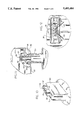
- FIG. 11 is a sectional view of taken substantially along lines 11--11 in FIG. 13;
- FIG. 12 is a top view of the support boss of FIG. 10 with the housing removed;
- FIG. 13 is a perspective view similar to FIG. 10 except showing the housing mounted on the support boss;
- FIG. 14 is a side view, similar to FIG. 3, except showing an alternate embodiment for use with a high pressure sodium lamp, the stand and electrical component enclosure being shown in section.
- FIG. 1 there is illustrated a portable quartz floodlight of the type generally available in the prior art having a housing H with top, bottom, side and rear walls forming a substantially rectangular opening.
- the housing H contains a quartz lamp (or other type of lamp) therein, a reflector mounted within the housing, a support stand S on which the housing is mounted, a front lens L, a wire safety guard G, and a carrying handle CH.
- the prior art stands generally comprise a pair of parallel feet upon which the stand is mounted.
- the stand curves upwardly and inwardly to form a horizontal lamp support to which a U-shaped bracket is attached.
- the lamp housing is then pivotally attached to the U-shaped bracket.
- the only place in this type of fixture for the mounting or provision of a switch, electrical connections, or a place for the incoming power line to be connected to the electrical components within the housing is by means of a splice box SB attached to the rear of the housing.
- This construction is relatively expensive and, since the stand generally rests on three horizontally disposed, elongated tubular members, it can be relatively unsteady if the support surface is not very flat.
- FIGS. 2-5 The floodlight and stand of the present invention is best illustrated in FIGS. 2-5.
- a stand 10 is provided to which a lamp housing 50 is attached.
- Support stand 10 includes a plurality of legs 12 extending downwardly from a domed top 14.
- a plurality of arcuate support bars 16 connect and support the legs 12 adjacent the lower ends thereof.
- a cover-plate 18 (FIG. 6) is attached to the stand 10 at a point beneath and spaced from the bottom of the domed portion 14.
- the cover-plate 18 forms a protective chamber 15 in the domed portion which protects the wire from the lamp and the electrical terminals from water and the elements.
- a waterproof switch 20 is mounted appropriately in the dome 14 with its terminals extending interiorly of the domed portion (FIG. 6).
- a plurality of attachment bosses 26 extend downwardly from the beneath the domed portion for attaching the cover-plate 18 as illustrated in FIG. 6 or for attaching the ballast enclosure as will be explained hereinafter.
- a support boss 30 extends upwardly from the domed portion 14 and includes a rounded upper end from which a stem 32 extends upwardly into the lamp housing 50 as will be described hereinafter.
- the configuration of the support boss 30 is best illustrated in FIGS. 10-13 and includes a generally rectangular upstanding block having a rounded upper end 31 and a stem or seat 32 extending upwardly from the central portion thereof.
- the boss 30 and stem 32 include a central passageway 33 therein through which the wires 23 from switch 20 extend to the lamp thereabove.
- a pair of threaded wells 34,35 also extend downwardly into the upper end of stem 32 to receive fasteners as will be hereinafter described.
- FIG. 12 there is shown a plan view of boss 30 and stem 32, a pair of angular passageways 37 each extends outwardly from the upper end of passageway 33.
- One of the wires 23 from switch 20 extend through each of the passageways 37 to route the wiring as required to position it away from the hot reflector 51.
- Housing 50 includes top, bottom, side, and rear walls forming a substantially rectangular front opening. As best illustrated in FIGS. 11 and 13, the lower rear portion of housing 50 includes a laterally extending slot 53 or opening through which stem 32 extends.
- the lower wall 52 of housing 50 includes a central rear recessed portion having a curved or arcuate configuration which contains the previously mentioned slot 53. The curved configuration is so configured as to rest on and compatibly pivot about the rounded portion 31 of boss 30.
- a front stop 54 and rear stop 56 are provided in the lower wall of housing 50 adjacent to the slot 53 to limit the movement of housing 50 in its arcuate path. Toward this end, the housing will cease rotation once either front stop 54 or rear stop 56 engages the stem 32.
- a retaining clip 60 is provided with a pair of openings 64 therein which correspond in size and spacing to align with the wells 34 in stem 32.
- a fastener 65 extends through each opening 64 in the clip 60 and into the threaded wells 34,35 for retaining the clip 60 thereon.
- the ends of the clips 60 rest on the spaced clip support walls 66 of housing 50 and act as a spring (FIG. 13).
- the screws 65 are tightened to provide the desired pressure exerted by the clip 60 against support walls 66. So arranged, the housing may be rotated merely by moving the housing against the spring pressure to position the housing as desired on stem 32. The housing will remain in the desired position until moved to a further position.
- a wire guard 80 is mounted to the front face of housing 50.
- wire guard 80 is of such a size and configuration as to allow housing 50 to rest therein. Therefore, the housing 50 and wire guard 80 nest together when disassembled for economies in shipping.
- housing 50 includes a front flange 72 having a peripheral recessed groove 74 extending therearound adjacent the inner portion thereof. As best shown in FIG. 8, recessed groove 74 is formed between the outer wall portion of flange 72 and the forwardly extending inner rim 75, which is generally an extension of the upper and lower wall of housing 50.
- a flat glass lens 76 is placed within the flange 72 and rests against the rim 75.
- flange 72 also includes upper and lower protrusions 78,79 respectively. Each protrusion includes an opening therein for receiving a fastener.
- Upper and lower retainer clips 81 are secured to the upper and lower protrusions 78,79 by means of fasteners to secure the glass lens 76 in place.
- housing 50 also includes one or more openings 55 in the bottom wall 52 or in the lower rear wall (FIG. 11) to allow excessive moisture to escape.
- the wire guard 80 is illustrated in FIGS. 3-6.
- Wire guard 80 is held in place by means of ears 84 which extend through slots 86 in the exterior wall of flange 72.
- ears 84 which extend through slots 86 in the exterior wall of flange 72.
- FIG. 9 there is illustrated the handle 90 and the manner in which it is retained in place.
- a unique slotted retainer 92 is formed in the upper surface of housing 50 immediately adjacent the rear of flange 72.
- the retainer 92 includes an opening therein through which the lower outer extensions of wire handle 90 extend.
- the opposed legs 91,93 are pushed together and the wire handle 90 is rotated until it is flat against the upper wall of housing 50.
- the handle is merely rotated upwardly to its normal position, whereupon the legs 91,93 are urged outwardly into the locking slots 95 in the retainer 92.
- the handle is thus retained in its upright position unless and until it is desired to fold the handle downwardly again, whereupon the above procedure is reversed.
- FIG. 14 there is illustrated an alternate embodiment of the fixture in which the lamp to be used is a high pressure sodium lamp.
- a ballast and ignitor are necessary.
- the cover-plate 18 has been removed and replaced by an enclosure or container 118.
- the enclosure contains the ballast 120 and ignitor (not illustrated).
- the enclosure 118 is suitably secured to one or more of the aforementioned bosses 126 which extend downwardly from the domed portion 114.
- the container 118 then serves to protect the electrical elements from the weather, moisture, dirt, etc.
Abstract
Description
Claims (31)
Priority Applications (1)
| Application Number | Priority Date | Filing Date | Title |
|---|---|---|---|
| US08/138,929 US5493484A (en) | 1993-10-18 | 1993-10-18 | Portable floodlight and stand |
Applications Claiming Priority (1)
| Application Number | Priority Date | Filing Date | Title |
|---|---|---|---|
| US08/138,929 US5493484A (en) | 1993-10-18 | 1993-10-18 | Portable floodlight and stand |
Publications (1)
| Publication Number | Publication Date |
|---|---|
| US5493484A true US5493484A (en) | 1996-02-20 |
Family
ID=22484303
Family Applications (1)
| Application Number | Title | Priority Date | Filing Date |
|---|---|---|---|
| US08/138,929 Expired - Fee Related US5493484A (en) | 1993-10-18 | 1993-10-18 | Portable floodlight and stand |
Country Status (1)
| Country | Link |
|---|---|
| US (1) | US5493484A (en) |
Cited By (7)
| Publication number | Priority date | Publication date | Assignee | Title |
|---|---|---|---|---|
| DE19608106A1 (en) * | 1996-03-02 | 1996-09-05 | Bernd Oswald Croesmann | Support frame for electric lamps |
| US5695278A (en) * | 1996-12-14 | 1997-12-09 | Regent Lighting Corporation | Worklight fixture with safety handles and integral storage compartment for additional bulb |
| US6231215B1 (en) * | 1999-06-15 | 2001-05-15 | Regent Lighting Corporation | Halogen tasklight |
| US6530680B2 (en) | 2001-05-01 | 2003-03-11 | Arthur E. Sipala | Utility flood light |
| US6595663B2 (en) * | 2001-02-07 | 2003-07-22 | Frank Tsao | Work light cage attachment system |
| US20040136192A1 (en) * | 2000-02-18 | 2004-07-15 | Carl Saieva | High intensity discharge (HID) lamp with integral ballast and underwater lighting systems incorporating same |
| US20100033977A1 (en) * | 2006-10-12 | 2010-02-11 | Arnold & Richter Cine Technik Gmbh & Co. Betriebs | Spotlight for illumination in film, studio, event or theatre environments |
Citations (14)
| Publication number | Priority date | Publication date | Assignee | Title |
|---|---|---|---|---|
| US1910779A (en) * | 1932-01-28 | 1933-05-23 | William D Stockman | Lens protector for head lamps |
| DE603893C (en) * | 1933-02-01 | 1934-10-11 | Schanzenbach & Co G M B H G | Waterproof electric lamp, the protective glass of which is held by a protective cage and pressed against the seal of the lamp body by an elastic component |
| US3254205A (en) * | 1963-07-01 | 1966-05-31 | Whiteway Mfg Company | Line beam illuminator |
| US3663808A (en) * | 1970-06-08 | 1972-05-16 | Traffic & Safety Control Syste | Illuminated safety curbing |
| US4413312A (en) * | 1982-05-21 | 1983-11-01 | Morkosky Sr Charles E | Portable, hangable lamp with outlets |
| US4489368A (en) * | 1983-12-27 | 1984-12-18 | Richard Sangiamo | High intensity discharge light fixture |
| US4626975A (en) * | 1985-03-25 | 1986-12-02 | Cooper Industries, Inc. | Flood light fixture construction |
| US4654764A (en) * | 1985-10-15 | 1987-03-31 | Hsiao Meng Chang | Rotary structure for the head portion of an illumination light |
| US4760508A (en) * | 1986-12-03 | 1988-07-26 | Keene Corporation | High intensity modular light fixture |
| US4760511A (en) * | 1986-12-03 | 1988-07-26 | Keene Corporation | Light fixture |
| US4796001A (en) * | 1986-01-16 | 1989-01-03 | North American Philips Corp. | Replacement ballast structures in roadway and/or area luminaires |
| US5195823A (en) * | 1992-05-06 | 1993-03-23 | Allied Wholesale, Inc. | Lamp and extension cord set |
| US5243507A (en) * | 1992-07-27 | 1993-09-07 | Atkins Donald W | Portable quartz floodlight fixture |
| US5307255A (en) * | 1993-02-02 | 1994-04-26 | Chen Chi Lin | Portable improved structure of quartz lamp |
-
1993
- 1993-10-18 US US08/138,929 patent/US5493484A/en not_active Expired - Fee Related
Patent Citations (14)
| Publication number | Priority date | Publication date | Assignee | Title |
|---|---|---|---|---|
| US1910779A (en) * | 1932-01-28 | 1933-05-23 | William D Stockman | Lens protector for head lamps |
| DE603893C (en) * | 1933-02-01 | 1934-10-11 | Schanzenbach & Co G M B H G | Waterproof electric lamp, the protective glass of which is held by a protective cage and pressed against the seal of the lamp body by an elastic component |
| US3254205A (en) * | 1963-07-01 | 1966-05-31 | Whiteway Mfg Company | Line beam illuminator |
| US3663808A (en) * | 1970-06-08 | 1972-05-16 | Traffic & Safety Control Syste | Illuminated safety curbing |
| US4413312A (en) * | 1982-05-21 | 1983-11-01 | Morkosky Sr Charles E | Portable, hangable lamp with outlets |
| US4489368A (en) * | 1983-12-27 | 1984-12-18 | Richard Sangiamo | High intensity discharge light fixture |
| US4626975A (en) * | 1985-03-25 | 1986-12-02 | Cooper Industries, Inc. | Flood light fixture construction |
| US4654764A (en) * | 1985-10-15 | 1987-03-31 | Hsiao Meng Chang | Rotary structure for the head portion of an illumination light |
| US4796001A (en) * | 1986-01-16 | 1989-01-03 | North American Philips Corp. | Replacement ballast structures in roadway and/or area luminaires |
| US4760508A (en) * | 1986-12-03 | 1988-07-26 | Keene Corporation | High intensity modular light fixture |
| US4760511A (en) * | 1986-12-03 | 1988-07-26 | Keene Corporation | Light fixture |
| US5195823A (en) * | 1992-05-06 | 1993-03-23 | Allied Wholesale, Inc. | Lamp and extension cord set |
| US5243507A (en) * | 1992-07-27 | 1993-09-07 | Atkins Donald W | Portable quartz floodlight fixture |
| US5307255A (en) * | 1993-02-02 | 1994-04-26 | Chen Chi Lin | Portable improved structure of quartz lamp |
Cited By (11)
| Publication number | Priority date | Publication date | Assignee | Title |
|---|---|---|---|---|
| DE19608106A1 (en) * | 1996-03-02 | 1996-09-05 | Bernd Oswald Croesmann | Support frame for electric lamps |
| DE19608106B4 (en) * | 1996-03-02 | 2009-08-06 | Crößmann, Bernd Oswald | Carrying unit for lighting devices |
| US5695278A (en) * | 1996-12-14 | 1997-12-09 | Regent Lighting Corporation | Worklight fixture with safety handles and integral storage compartment for additional bulb |
| US6231215B1 (en) * | 1999-06-15 | 2001-05-15 | Regent Lighting Corporation | Halogen tasklight |
| US20040136192A1 (en) * | 2000-02-18 | 2004-07-15 | Carl Saieva | High intensity discharge (HID) lamp with integral ballast and underwater lighting systems incorporating same |
| US7314290B2 (en) | 2000-02-18 | 2008-01-01 | Sartek Llc | High intensity discharge (HID) lamp with integral ballast and underwater lighting systems incorporating same |
| US7524086B1 (en) | 2000-02-18 | 2009-04-28 | Sartek, Llc | High intensity discharge (HID) lamp with integral ballast and underwater lighting systems incorporating same |
| US6595663B2 (en) * | 2001-02-07 | 2003-07-22 | Frank Tsao | Work light cage attachment system |
| US6530680B2 (en) | 2001-05-01 | 2003-03-11 | Arthur E. Sipala | Utility flood light |
| US20100033977A1 (en) * | 2006-10-12 | 2010-02-11 | Arnold & Richter Cine Technik Gmbh & Co. Betriebs | Spotlight for illumination in film, studio, event or theatre environments |
| US7815437B2 (en) * | 2006-10-12 | 2010-10-19 | Arnold & Richter Cine Technik Gmbh & Co. Betriebs Kg | Spotlight for illumination in film, studio, event or theatre environments |
Similar Documents
| Publication | Publication Date | Title |
|---|---|---|
| US5408399A (en) | Portable quartz floodlight fixture | |
| US6059422A (en) | Canopy luminaire | |
| USD328785S (en) | Combined electric ceiling fan and light | |
| US5556188A (en) | Wet niche light | |
| US4951182A (en) | Modular plastic power-light pedestal enclosure | |
| US20020136003A1 (en) | Canopy luminaire assembly | |
| US5493484A (en) | Portable floodlight and stand | |
| US4156272A (en) | Mounting bracket for light fixture | |
| US7036960B1 (en) | Light louver post | |
| US4787018A (en) | Outdoor electric lighting fixture | |
| US7360916B2 (en) | Under-cabinet light fixture | |
| US4503489A (en) | Above ground low voltage underwater light | |
| AU660517B2 (en) | Device for lighting and suspension of a hanging-rod and modular assembly for lighting and suspension of hanging-rods | |
| US10935229B2 (en) | Adjustable lighting fixture for decorative light | |
| US20010022728A1 (en) | Barrier wall mounting plate for electrical fixture enclosure | |
| CA1249804A (en) | Adjustable lighting luminaire | |
| GB2346741A (en) | Light socket assembly | |
| US7077537B2 (en) | Underwater light for soft-sided aboveground pools | |
| US4413312A (en) | Portable, hangable lamp with outlets | |
| JPH05190012A (en) | Direct-attachment-to-ceiling type of luminaire | |
| CN213513583U (en) | Concave type light-emitting projection lamp | |
| CN216644002U (en) | Outdoor lighting device with waterproof dustproof function | |
| KR102262767B1 (en) | A Rail Type Lamp Fixture Apparatus | |
| JP3766648B2 (en) | Small waterproof lamp | |
| CN209960291U (en) | Wall lamp |
Legal Events
| Date | Code | Title | Description |
|---|---|---|---|
| AS | Assignment |
Owner name: REGENT LIGHTING CORP., NORTH CAROLINA Free format text: ASSIGNMENT OF ASSIGNORS INTEREST;ASSIGNORS:OSTEEN, MITCHELL M.;SUMER, SULEYMAN O.;DOZIER, CHARLES L.;REEL/FRAME:006739/0276 Effective date: 19931008 |
|
| AS | Assignment |
Owner name: REGENT ACQUISITION CORP., A CORP. OF DELAWARE, NOR Free format text: ASSIGNMENT OF ASSIGNORS INTEREST;ASSIGNOR:REGENT LIGHTING CORPORATION;REEL/FRAME:007588/0669 Effective date: 19950817 Owner name: BANQUE NATIONAL DE PARIS, NEW YORK BRANCH, A NY BA Free format text: SECURITY INTEREST;ASSIGNOR:REGENT ACQUISITION CORP.;REEL/FRAME:007588/0876 Effective date: 19950817 |
|
| AS | Assignment |
Owner name: REGENT LIGHTING CORPORATION, NORTH CAROLINA Free format text: ASSIGNMENT OF ASSIGNORS INTEREST;ASSIGNOR:REGENT ACQUISITION CORPORATION;REEL/FRAME:009547/0646 Effective date: 19981012 |
|
| FEPP | Fee payment procedure |
Free format text: PAYOR NUMBER ASSIGNED (ORIGINAL EVENT CODE: ASPN); ENTITY STATUS OF PATENT OWNER: LARGE ENTITY |
|
| FPAY | Fee payment |
Year of fee payment: 4 |
|
| FEPP | Fee payment procedure |
Free format text: PAT HOLDER NO LONGER CLAIMS SMALL ENTITY STATUS, ENTITY STATUS SET TO UNDISCOUNTED (ORIGINAL EVENT CODE: STOL); ENTITY STATUS OF PATENT OWNER: LARGE ENTITY |
|
| REFU | Refund |
Free format text: REFUND - 7.5 YR SURCHARGE - LATE PMT W/IN 6 MO, LARGE ENTITY (ORIGINAL EVENT CODE: R1555); ENTITY STATUS OF PATENT OWNER: LARGE ENTITY Free format text: REFUND - PAYMENT OF MAINTENANCE FEE, 8TH YEAR, LARGE ENTITY (ORIGINAL EVENT CODE: R1552); ENTITY STATUS OF PATENT OWNER: LARGE ENTITY Free format text: REFUND - PAYMENT OF MAINTENANCE FEE, 8TH YR, SMALL ENTITY (ORIGINAL EVENT CODE: R2552); ENTITY STATUS OF PATENT OWNER: LARGE ENTITY |
|
| FPAY | Fee payment |
Year of fee payment: 8 |
|
| FEPP | Fee payment procedure |
Free format text: PAYOR NUMBER ASSIGNED (ORIGINAL EVENT CODE: ASPN); ENTITY STATUS OF PATENT OWNER: LARGE ENTITY Free format text: PAYER NUMBER DE-ASSIGNED (ORIGINAL EVENT CODE: RMPN); ENTITY STATUS OF PATENT OWNER: LARGE ENTITY |
|
| REMI | Maintenance fee reminder mailed | ||
| LAPS | Lapse for failure to pay maintenance fees | ||
| STCH | Information on status: patent discontinuation |
Free format text: PATENT EXPIRED DUE TO NONPAYMENT OF MAINTENANCE FEES UNDER 37 CFR 1.362 |
|
| FP | Lapsed due to failure to pay maintenance fee |
Effective date: 20080220 |