US5487701A - Plastic foundation vent - Google Patents
Plastic foundation vent Download PDFInfo
- Publication number
- US5487701A US5487701A US08/262,237 US26223794A US5487701A US 5487701 A US5487701 A US 5487701A US 26223794 A US26223794 A US 26223794A US 5487701 A US5487701 A US 5487701A
- Authority
- US
- United States
- Prior art keywords
- flange
- plastic
- short sides
- foundation vent
- set forth
- Prior art date
- Legal status (The legal status is an assumption and is not a legal conclusion. Google has not performed a legal analysis and makes no representation as to the accuracy of the status listed.)
- Expired - Lifetime
Links
Images


Classifications
-
- F—MECHANICAL ENGINEERING; LIGHTING; HEATING; WEAPONS; BLASTING
- F24—HEATING; RANGES; VENTILATING
- F24F—AIR-CONDITIONING; AIR-HUMIDIFICATION; VENTILATION; USE OF AIR CURRENTS FOR SCREENING
- F24F13/00—Details common to, or for air-conditioning, air-humidification, ventilation or use of air currents for screening
- F24F13/08—Air-flow control members, e.g. louvres, grilles, flaps or guide plates
Definitions
- This invention relates to foundation vents and particularly to a plastic foundation vent.
- foundation vent which is usually placed in an opening in the wall or foundation.
- the foundation may consist of a cement block wall or a poured concrete wall.
- Such foundation vents become damaged and require replacement which is difficult and not readily done.
- a plastic foundation vent which can be used in new construction; which can be readily applied as a replacement vent; and which can be adapted for use in an opening that has siding and the like associated therewith.
- the plastic foundation vent embodying the invention comprises a plastic body with an integral peripheral rectangular wall surrounding the plastic body and defining opposed long sides and opposed short sides.
- An integral peripheral flange extends outwardly from the peripheral wall.
- a central integral screen portion having openings for bending and prevention of entry of animals and the like is provided within the peripheral wall.
- the peripheral flange has a front surface and a rear surface.
- a first groove is provided on the rear surface of one of the flanges alongside to define a live hinge line permitting the flange to be bent backwardly or forwardly.
- a second groove on the front surface of the flange on each of the short sides permits bending of the flange along the short sides.
- a third groove on the front surface of the flange along the short sides permits bending of the short sides about a second live hinge.
- Cutting lines are provided at right angles on the flange having live hinge to permit corners of the flange to be cut for use in replacement of a foundation vent.
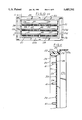
- FIG. 1 is a front elevational view of a plastic foundation vent embodying the invention.
- FIG. 2 is a rear elevational view of a plastic foundation vent.
- FIG. 3 is a top view showing the plastic foundation vent of FIGS. 1 and 2 in a cement block wall taken along the line 3--3 in FIG. 4.
- FIG. 4 is a front elevational view of the wall shown in FIG. 3.
- FIG. 5 is a fragmentary sectional view taken along the lines 5--5 in FIG. 4, on an enlarged scale.
- FIG. 6 is a sectional view taken along the lines 6--6 in FIG. 4.
- FIG. 7 is a fragmentary front elevational view on an enlarged scale.
- FIG. 8 is a fragmentary plan view of a louver utilized in the foundation vent.
- FIG. 9 is an end view of the louver.
- FIG. 10 is a front elevational view of the plastic foundation vent showing the louver in open position.
- FIG. 11 is a sectional view taken along the lines 11--11 in FIG. 10 with the louvers removed.
- FIG. 12 is a front elevational view of the plastic foundation vent as utilized as a replacement in an existing foundation.
- FIG. 13 is a sectional view taken along the line 13--13 in FIG. 12.
- FIG. 14 is a front elevational view of the plastic foundation vent as provided in an opening in a wall that has siding surrounding the opening.
- FIG. 15 is a sectional view taken along the line 15--15 in FIG. 14.
- FIG. 16 is a fragmentary sectional view taken along the lines 16--16 in FIG. 14.
- the plastic foundation vent 20 embodying the invention comprises a plastic body 21 with an integral peripheral rectangular wall 22 surrounding the plastic body and defining opposed long sides 22a, 22b and opposed short sides 22c, 22d.
- An integral peripheral flange 23 extends outwardly from the peripheral wall.
- a central integral screen portion 24 having spaced portions 25 with openings for venting and prevention of entry of animals and the like is provided within the peripheral wall 22.
- the plastic foundation vent is preferably made by injection molding.
- a preferred plastic is polypropylene.
- the peripheral flange 23 has a front surface and a rear surface.
- a first groove 26 is provided on the rear surface of one portion 23a of the flange 23 on a long side 22a to define a live hinge line permitting portion 23a to bend backwardly or forwardly.
- Second grooves 27a, 27b on the front surface of the flange portion 23c, 23d on each of the short sides permits bending of the flange portions 23c, 23d along the short sides.
- a third groove 28 on the front surface of the flange along the short sides permits bending of the short sides about a second live hinge.
- Cutting lines 30a, 30b are provided at right angles on the flange portion 23a having live hinge to permit corners of the flange portion 23a to be cut for use in replacement of a foundation vent.
- the plastic foundation vent 20 is provided with a plurality of vertically spaced and horizontally extending movable louvers 35.
- Each louver includes an upper pivot end 36 and a lower bent end 37.
- Each louver further includes a laterally extending projection 38 that engages an opening 39 (FIG. 11) which is non-circular, herein shown as square into which the rectangular projection 39 extends.
- Each louver 35 can be grasped and snapped outwardly and upwardly to an open position and is held in an open position by lateral tabs 40 which engage the peripheral wall 22.
- each louver has a centrally located upwardly extending recess 42 into which the finger of a user can be inserted to raise the louver 35 to the open position.
- the peripheral wall 22 includes a recess 43 adjacent the lowest louver to further facilitate operation of the louvers (FIG. 7).
- the plastic foundation vent 20 embodying the invention can be utilized in new construction by bending flange portions 23c, 23d rearwardly along second hinge lines 27a, 27b and inserting the plastic foundation vent 20 downwardly into grooves G of cement blocks B that form the foundation (FIG. 3).
- a wood cross member C can then be applied in over relying relationship to the plastic vent after the flange portion 23a is bent rearwardly along the hinge line formed by groove 26 (FIG. 4).
- the plastic foundation vent 20 can be utilized as a replacement foundation vent where the existing foundation vent has been damaged by removing the existing foundation vent from the opening defined in the building.
- the corners of the top flanges are cut off and the side flanges are folded along the hinge lines 26, 28 so that the side peripheral flange 23c, 23d and top flange 22a extend rearwardly.
- the foundation vent 20 is then inserted into the opening. If accessible from the interior, cement nail N can be provided to hold the vent in position.
- the plastic foundation vent 20 embodying the invention can also be used as a replacement vent in buildings having plastic siding S as shown in FIGS. 14-16 where the peripheral flange 23 is nailed to the foundation and the siding S is brought into overlapping relation to the flange 23.
- the plastic foundation vent includes a peripheral ring 50 that has axially spaced teeth 51 engaging the teeth 52 on the peripheral wall 22 substantially as shown in U.S. Pat. No. 4,875,318, incorporated herein by reference.
- indicia are provided to facilitate the user.
- each of the flanges has instructions for usage that includes the indicia for the user.
- indicia are provided on the top flange calling for with an arrow and indicia "FOLD HERE FOR REPLACEMENT APPLICATION".
- Further indicia on the top flange define the top or upper part of the plastic foundation vent.
- a plastic foundation vent which comprises a plastic body with an integral peripheral rectangular wall surrounding the plastic body and defining opposed long sides and opposed short sides.
- An integral peripheral flange extends outwardly from the peripheral wall.
- a central integral screen portion having openings for bending and prevention of entry of animals and the like is provided within the peripheral wall.
- the peripheral flange has a front surface and a rear surface.
- a first groove is provided on the rear surface of one of the flanges alongside to define a live hinge line permitting the flange to be bent backwardly or forwardly.
- a second groove on the front surface of the flange on each of the short sides permits bending of the flange along the short sides.
- a third groove on the front surface of the flange along the short sides permits bending of the short sides about a second live hinge.
- Cutting lines are provided at right angles on the flange having live hinge to permit corners of the flange to be cut for use in replacement of a foundation vent.
Abstract
Description
Claims (10)
Priority Applications (1)
| Application Number | Priority Date | Filing Date | Title |
|---|---|---|---|
| US08/262,237 US5487701A (en) | 1994-06-20 | 1994-06-20 | Plastic foundation vent |
Applications Claiming Priority (1)
| Application Number | Priority Date | Filing Date | Title |
|---|---|---|---|
| US08/262,237 US5487701A (en) | 1994-06-20 | 1994-06-20 | Plastic foundation vent |
Publications (1)
| Publication Number | Publication Date |
|---|---|
| US5487701A true US5487701A (en) | 1996-01-30 |
Family
ID=22996736
Family Applications (1)
| Application Number | Title | Priority Date | Filing Date |
|---|---|---|---|
| US08/262,237 Expired - Lifetime US5487701A (en) | 1994-06-20 | 1994-06-20 | Plastic foundation vent |
Country Status (1)
| Country | Link |
|---|---|
| US (1) | US5487701A (en) |
Cited By (44)
| Publication number | Priority date | Publication date | Assignee | Title |
|---|---|---|---|---|
| USD386735S (en) * | 1996-05-06 | 1997-11-25 | White Consolidated Industries, Inc. | Side vent frame |
| US5758457A (en) * | 1996-03-15 | 1998-06-02 | Achen; John J. | Vent with security grate |
| US5944445A (en) * | 1997-07-10 | 1999-08-31 | Smart Vent, Inc. | Device and method for relieving flooding from enclosed space |
| US5976009A (en) * | 1996-03-15 | 1999-11-02 | Achen; John J. | Vent with multi-apertured security grate |
| US6287050B1 (en) | 1997-07-10 | 2001-09-11 | Smart Vent, Inc. | Foundation flood gate with ventilation |
| US6431980B1 (en) | 2000-12-21 | 2002-08-13 | John J. Achen | Combustion air security vent |
| US6485231B2 (en) | 1997-07-10 | 2002-11-26 | Smart Vent, Inc. | Foundation flood gate with ventilation |
| US6484459B1 (en) * | 2000-07-26 | 2002-11-26 | Robert E. Platts | Counter-pressure method and apparatus for protecting roofs against hurricanes |
| US20030082008A1 (en) * | 1997-07-10 | 2003-05-01 | Sprengle E. Carl | Flood gate for door |
| US6669554B1 (en) | 2002-08-26 | 2003-12-30 | John Tregidga | Ventilating sill plate for crawl spaces |
| US20040058638A1 (en) * | 2002-09-13 | 2004-03-25 | Achen John J. | Moisture resistant wall vent |
| US6746324B2 (en) | 2002-09-13 | 2004-06-08 | John J. Achen | Combustion air wall vent |
| US20040126188A1 (en) * | 2001-03-22 | 2004-07-01 | Jin-Hwan Kim | Device installed at a ditch on a road, to prevent back flow of sewage and malodor |
| US20040221522A1 (en) * | 2003-05-09 | 2004-11-11 | HENDRICKS Robert | Single piece mounting frame |
| US20060223434A1 (en) * | 2005-03-29 | 2006-10-05 | The Holmes Group, Inc. | System and method for mounting a fresh air exchanger to a window frame assembly |
| US20070010190A1 (en) * | 2005-07-05 | 2007-01-11 | Canplas Industries Ltd. | Foundation vent |
| US20070033888A1 (en) * | 2003-05-09 | 2007-02-15 | HENDRICKS Robert | Cap-on-cap mounting block |
| US20070232217A1 (en) * | 2006-04-04 | 2007-10-04 | Davis Michael C | Vent cover |
| US20070266659A1 (en) * | 2006-05-22 | 2007-11-22 | Lapierre Alan Wayne | Perimeter foundation panel, and method of use |
| US20090071087A1 (en) * | 2007-04-05 | 2009-03-19 | Achen John J | Garage door vent with screen |
| US20090148236A1 (en) * | 2007-12-07 | 2009-06-11 | Achen John J | Flood and combustion air vent |
| US7600944B1 (en) * | 2007-10-31 | 2009-10-13 | Keating John J | Flood vent |
| US7640710B1 (en) * | 2006-05-24 | 2010-01-05 | Mcatee Joseph P | Method for replacing a louvered panel mounted in a finished opening |
| US20100086358A1 (en) * | 2008-10-07 | 2010-04-08 | William Anthony Haryslak | Multi-Purpose Vent |
| US7780509B1 (en) | 2006-11-30 | 2010-08-24 | John Charles Hoaks | Quick-install foundation vent |
| US7926539B1 (en) * | 2008-10-31 | 2011-04-19 | Hurst Steven L | Flood vent access door assembly |
| US20110182669A1 (en) * | 2010-01-22 | 2011-07-28 | Shook Ted A | Flood vent |
| US20130233426A1 (en) * | 2012-03-12 | 2013-09-12 | Hon Hai Precision Industry Co., Ltd. | Air duct |
| US20150107170A1 (en) * | 2013-10-23 | 2015-04-23 | Zachary Dax Olkin | Flood shield systems and methods |
| US20160047102A1 (en) * | 2014-08-14 | 2016-02-18 | Nan Dao Engineering Corp. | Inflatable flood barrier |
| US9341388B2 (en) * | 2012-09-24 | 2016-05-17 | Christopher Michael Francescon | Sliding foundation vent |
| US9353569B1 (en) * | 2015-04-08 | 2016-05-31 | Smart Vent Products, Inc. | Connectors for a flood vent |
| US9376803B1 (en) | 2015-04-08 | 2016-06-28 | Smart Vent Products, Inc. | Flood vent trigger systems |
| US9551153B2 (en) | 2015-04-08 | 2017-01-24 | Smart Vent Products, Inc. | Scupper door systems |
| US9624637B2 (en) | 2015-04-08 | 2017-04-18 | Smart Vent Products, Inc. | Flood vent |
| US9637912B1 (en) | 2015-12-10 | 2017-05-02 | Smart Vent Products, Inc. | Flood vent having a panel |
| US9719249B2 (en) | 2015-12-10 | 2017-08-01 | Smart Vent Products, Inc. | Flood vent having a panel |
| US9758982B2 (en) | 2015-12-10 | 2017-09-12 | Smart Vent Products, Inc. | Flood vent having a panel |
| US10113309B2 (en) | 2015-04-08 | 2018-10-30 | Smart Vent Products, Inc. | Flood vent barrier systems |
| US10385611B2 (en) * | 2015-12-10 | 2019-08-20 | Smart Vent Products, Inc. | Flood vent having a panel |
| US10619345B2 (en) * | 2015-12-10 | 2020-04-14 | Smart Vent Products, Inc. | Flood vent having a panel |
| US11519618B1 (en) * | 2021-02-17 | 2022-12-06 | Gregory White | Foundation dryer vent |
| US11609003B1 (en) * | 2021-02-17 | 2023-03-21 | Gregory White | Clothes dryer exhaust vent for building exterior wall |
| US11661751B2 (en) | 2020-04-20 | 2023-05-30 | Sebastien Marcil | Moisture barrier molding to reduce water damage on walls |
Citations (14)
| Publication number | Priority date | Publication date | Assignee | Title |
|---|---|---|---|---|
| US1673379A (en) * | 1926-10-30 | 1928-06-12 | Swift Matthew Dean | Ventilator |
| US2116457A (en) * | 1937-08-23 | 1938-05-03 | James H Whitmarsh | Ventilating building block |
| US2505147A (en) * | 1947-08-12 | 1950-04-25 | Frank J Scallon | Ventilating device |
| US2611310A (en) * | 1947-05-27 | 1952-09-23 | Air Rectifiers Inc | Ventilating wall block |
| US3192849A (en) * | 1963-04-22 | 1965-07-06 | Richard D Massengale | Vent construction |
| US3220079A (en) * | 1963-12-16 | 1965-11-30 | Robert E Aggson | Foundation vent |
| US4175480A (en) * | 1978-01-13 | 1979-11-27 | Beam Dennis A Jr | Wall ventilator construction |
| US4249460A (en) * | 1979-08-23 | 1981-02-10 | Mcswain Edward D | Wall ventilator construction |
| US4274330A (en) * | 1979-07-09 | 1981-06-23 | Witten Automatic Vent Company, Inc. | Ventilator and mounting frame assembly |
| US4592271A (en) * | 1985-08-16 | 1986-06-03 | Young Lester L | Louvered vent |
| US4669371A (en) * | 1986-01-27 | 1987-06-02 | Sarazen Jr Paul M | Ventilator mounting spring |
| US4875318A (en) * | 1988-05-10 | 1989-10-24 | Tapco Products Company, Inc. | Plastic building product |
| US5293920A (en) * | 1993-07-08 | 1994-03-15 | Michael Vagedes | Louvered basement vent |
| US5349799A (en) * | 1993-08-25 | 1994-09-27 | Mid-America Building Products Corporation | Plastic gable vent |
-
1994
- 1994-06-20 US US08/262,237 patent/US5487701A/en not_active Expired - Lifetime
Patent Citations (14)
| Publication number | Priority date | Publication date | Assignee | Title |
|---|---|---|---|---|
| US1673379A (en) * | 1926-10-30 | 1928-06-12 | Swift Matthew Dean | Ventilator |
| US2116457A (en) * | 1937-08-23 | 1938-05-03 | James H Whitmarsh | Ventilating building block |
| US2611310A (en) * | 1947-05-27 | 1952-09-23 | Air Rectifiers Inc | Ventilating wall block |
| US2505147A (en) * | 1947-08-12 | 1950-04-25 | Frank J Scallon | Ventilating device |
| US3192849A (en) * | 1963-04-22 | 1965-07-06 | Richard D Massengale | Vent construction |
| US3220079A (en) * | 1963-12-16 | 1965-11-30 | Robert E Aggson | Foundation vent |
| US4175480A (en) * | 1978-01-13 | 1979-11-27 | Beam Dennis A Jr | Wall ventilator construction |
| US4274330A (en) * | 1979-07-09 | 1981-06-23 | Witten Automatic Vent Company, Inc. | Ventilator and mounting frame assembly |
| US4249460A (en) * | 1979-08-23 | 1981-02-10 | Mcswain Edward D | Wall ventilator construction |
| US4592271A (en) * | 1985-08-16 | 1986-06-03 | Young Lester L | Louvered vent |
| US4669371A (en) * | 1986-01-27 | 1987-06-02 | Sarazen Jr Paul M | Ventilator mounting spring |
| US4875318A (en) * | 1988-05-10 | 1989-10-24 | Tapco Products Company, Inc. | Plastic building product |
| US5293920A (en) * | 1993-07-08 | 1994-03-15 | Michael Vagedes | Louvered basement vent |
| US5349799A (en) * | 1993-08-25 | 1994-09-27 | Mid-America Building Products Corporation | Plastic gable vent |
Cited By (63)
| Publication number | Priority date | Publication date | Assignee | Title |
|---|---|---|---|---|
| US5976009A (en) * | 1996-03-15 | 1999-11-02 | Achen; John J. | Vent with multi-apertured security grate |
| US5758457A (en) * | 1996-03-15 | 1998-06-02 | Achen; John J. | Vent with security grate |
| USD386735S (en) * | 1996-05-06 | 1997-11-25 | White Consolidated Industries, Inc. | Side vent frame |
| US6485231B2 (en) | 1997-07-10 | 2002-11-26 | Smart Vent, Inc. | Foundation flood gate with ventilation |
| US6287050B1 (en) | 1997-07-10 | 2001-09-11 | Smart Vent, Inc. | Foundation flood gate with ventilation |
| US20030082008A1 (en) * | 1997-07-10 | 2003-05-01 | Sprengle E. Carl | Flood gate for door |
| US6692187B2 (en) * | 1997-07-10 | 2004-02-17 | Smart Vent, Inc. | Flood gate for door |
| US5944445A (en) * | 1997-07-10 | 1999-08-31 | Smart Vent, Inc. | Device and method for relieving flooding from enclosed space |
| US6484459B1 (en) * | 2000-07-26 | 2002-11-26 | Robert E. Platts | Counter-pressure method and apparatus for protecting roofs against hurricanes |
| US6431980B1 (en) | 2000-12-21 | 2002-08-13 | John J. Achen | Combustion air security vent |
| US20040126188A1 (en) * | 2001-03-22 | 2004-07-01 | Jin-Hwan Kim | Device installed at a ditch on a road, to prevent back flow of sewage and malodor |
| US6866444B2 (en) * | 2001-03-22 | 2005-03-15 | My's Tech Co., Ltd | Device installed at a ditch on a road, to prevent back flow of sewage and malodor |
| US6669554B1 (en) | 2002-08-26 | 2003-12-30 | John Tregidga | Ventilating sill plate for crawl spaces |
| US6875102B2 (en) | 2002-09-13 | 2005-04-05 | John J. Achen | Moisture resistant wall vent |
| US6746324B2 (en) | 2002-09-13 | 2004-06-08 | John J. Achen | Combustion air wall vent |
| US20040058638A1 (en) * | 2002-09-13 | 2004-03-25 | Achen John J. | Moisture resistant wall vent |
| US20040221522A1 (en) * | 2003-05-09 | 2004-11-11 | HENDRICKS Robert | Single piece mounting frame |
| US8572910B2 (en) | 2003-05-09 | 2013-11-05 | Tapco International, Inc. | Cap-on-cap mounting block |
| US20070033888A1 (en) * | 2003-05-09 | 2007-02-15 | HENDRICKS Robert | Cap-on-cap mounting block |
| US7510153B2 (en) | 2003-05-09 | 2009-03-31 | Tapco International Corporation | Single piece mounting frame |
| US20060223434A1 (en) * | 2005-03-29 | 2006-10-05 | The Holmes Group, Inc. | System and method for mounting a fresh air exchanger to a window frame assembly |
| US20070010190A1 (en) * | 2005-07-05 | 2007-01-11 | Canplas Industries Ltd. | Foundation vent |
| US20070232217A1 (en) * | 2006-04-04 | 2007-10-04 | Davis Michael C | Vent cover |
| US20070266659A1 (en) * | 2006-05-22 | 2007-11-22 | Lapierre Alan Wayne | Perimeter foundation panel, and method of use |
| US7640710B1 (en) * | 2006-05-24 | 2010-01-05 | Mcatee Joseph P | Method for replacing a louvered panel mounted in a finished opening |
| US7780509B1 (en) | 2006-11-30 | 2010-08-24 | John Charles Hoaks | Quick-install foundation vent |
| US20090071087A1 (en) * | 2007-04-05 | 2009-03-19 | Achen John J | Garage door vent with screen |
| US7600944B1 (en) * | 2007-10-31 | 2009-10-13 | Keating John J | Flood vent |
| US20090148236A1 (en) * | 2007-12-07 | 2009-06-11 | Achen John J | Flood and combustion air vent |
| US7909686B2 (en) | 2007-12-07 | 2011-03-22 | Achen John J | Flood and combustion air vent |
| US20110225912A1 (en) * | 2007-12-07 | 2011-09-22 | Achen John J | Block wall and garage door flood and combustion air vent |
| US20100086358A1 (en) * | 2008-10-07 | 2010-04-08 | William Anthony Haryslak | Multi-Purpose Vent |
| US7926539B1 (en) * | 2008-10-31 | 2011-04-19 | Hurst Steven L | Flood vent access door assembly |
| US20110182669A1 (en) * | 2010-01-22 | 2011-07-28 | Shook Ted A | Flood vent |
| US8308396B2 (en) | 2010-01-22 | 2012-11-13 | Ted Shook | Flood vent |
| US20130233426A1 (en) * | 2012-03-12 | 2013-09-12 | Hon Hai Precision Industry Co., Ltd. | Air duct |
| US9341388B2 (en) * | 2012-09-24 | 2016-05-17 | Christopher Michael Francescon | Sliding foundation vent |
| US20150107170A1 (en) * | 2013-10-23 | 2015-04-23 | Zachary Dax Olkin | Flood shield systems and methods |
| US9303448B2 (en) * | 2013-10-23 | 2016-04-05 | Zachary Dax Olkin | Flood shield systems and methods |
| US9745795B2 (en) * | 2014-08-14 | 2017-08-29 | Nan Dao Engineering Corp. | Inflatable flood barrier |
| US20160047102A1 (en) * | 2014-08-14 | 2016-02-18 | Nan Dao Engineering Corp. | Inflatable flood barrier |
| US9353569B1 (en) * | 2015-04-08 | 2016-05-31 | Smart Vent Products, Inc. | Connectors for a flood vent |
| US10113286B2 (en) | 2015-04-08 | 2018-10-30 | Smart Vent Products, Inc. | Flood vent |
| US9624637B2 (en) | 2015-04-08 | 2017-04-18 | Smart Vent Products, Inc. | Flood vent |
| US10619319B2 (en) | 2015-04-08 | 2020-04-14 | Smart Vent Products, Inc. | Flood vent |
| US9670717B2 (en) | 2015-04-08 | 2017-06-06 | Smart Vent Products, Inc. | Flood vent trigger systems |
| US9551153B2 (en) | 2015-04-08 | 2017-01-24 | Smart Vent Products, Inc. | Scupper door systems |
| US9376803B1 (en) | 2015-04-08 | 2016-06-28 | Smart Vent Products, Inc. | Flood vent trigger systems |
| US10113309B2 (en) | 2015-04-08 | 2018-10-30 | Smart Vent Products, Inc. | Flood vent barrier systems |
| US10584510B2 (en) | 2015-12-10 | 2020-03-10 | Smart Vent Products, Inc. | Flood vent having a panel |
| US9909302B2 (en) | 2015-12-10 | 2018-03-06 | Smart Vent Products, Inc. | Flood vent having a panel |
| US9758982B2 (en) | 2015-12-10 | 2017-09-12 | Smart Vent Products, Inc. | Flood vent having a panel |
| US9719249B2 (en) | 2015-12-10 | 2017-08-01 | Smart Vent Products, Inc. | Flood vent having a panel |
| US10161156B2 (en) | 2015-12-10 | 2018-12-25 | Smart Vent Products, Inc. | Flood vent having a panel |
| US10385611B2 (en) * | 2015-12-10 | 2019-08-20 | Smart Vent Products, Inc. | Flood vent having a panel |
| US10017937B2 (en) | 2015-12-10 | 2018-07-10 | Smart Vent Products, Inc. | Flood vent having a panel |
| US9637912B1 (en) | 2015-12-10 | 2017-05-02 | Smart Vent Products, Inc. | Flood vent having a panel |
| US11021886B2 (en) | 2015-12-10 | 2021-06-01 | Smart Vent Products, Inc. | Flood vent having a panel |
| US11002006B2 (en) * | 2015-12-10 | 2021-05-11 | Smart Vent Products, Inc. | Flood vent having a panel |
| US10619345B2 (en) * | 2015-12-10 | 2020-04-14 | Smart Vent Products, Inc. | Flood vent having a panel |
| US11661751B2 (en) | 2020-04-20 | 2023-05-30 | Sebastien Marcil | Moisture barrier molding to reduce water damage on walls |
| US11519618B1 (en) * | 2021-02-17 | 2022-12-06 | Gregory White | Foundation dryer vent |
| US11609003B1 (en) * | 2021-02-17 | 2023-03-21 | Gregory White | Clothes dryer exhaust vent for building exterior wall |
Similar Documents
| Publication | Publication Date | Title |
|---|---|---|
| US5487701A (en) | Plastic foundation vent | |
| US4669371A (en) | Ventilator mounting spring | |
| US2877600A (en) | Fence construction | |
| US6212841B1 (en) | Brick tie, in moulded plastic | |
| US4202145A (en) | Cast-in-place concrete slab pouring form | |
| BR9507928A (en) | Modular block retaining wall system and construction process | |
| US4742585A (en) | Tub box | |
| US2918814A (en) | Wall tile | |
| CA2387181A1 (en) | An artificial piece of masonry and a kit for forming a masonry wall | |
| US3656651A (en) | Drawer divider | |
| US4879818A (en) | Clapboard slide gauge | |
| EP0003470B1 (en) | Saliva ejector | |
| EP0056173A1 (en) | Air grating for use in the masonry of a building | |
| GB2049779A (en) | Spacer for bricks | |
| US4411404A (en) | Holding clips for stakes supporting metal concrete forms | |
| JPH0586687A (en) | Intersecting point binding bearing device of pc slab sheath | |
| IT1267472B1 (en) | BENDING PRESS FOR THE EXECUTION OF C-BENDS ON THE FOUR EDGES OF A SHEET PANEL. | |
| GB2263288A (en) | Cavity tray | |
| DE69403769D1 (en) | CAN WITH A LARGE TOP EMPTYING OPENING | |
| GB2146678A (en) | Wedge for retaining flashing | |
| US11684062B2 (en) | Weep hole guard | |
| JPS6349229Y2 (en) | ||
| JPS6349228Y2 (en) | ||
| EP0674064A1 (en) | Kit and method and template for forming an arch | |
| AU598879B2 (en) | Improved light fitting end cap |
Legal Events
| Date | Code | Title | Description |
|---|---|---|---|
| AS | Assignment |
Owner name: MID-AMERICA BUILDING PRODUCTS CORPORATION, MICHIGA Free format text: ASSIGNMENT OF ASSIGNORS INTEREST;ASSIGNORS:SCHIEDEGGER, CHARLES E.;ALLEN, CLYDE G.;CLARK, MICHAEL C.;AND OTHERS;REEL/FRAME:007071/0969 Effective date: 19940613 |
|
| STCF | Information on status: patent grant |
Free format text: PATENTED CASE |
|
| FEPP | Fee payment procedure |
Free format text: PAT HLDR NO LONGER CLAIMS SMALL ENT STAT AS SMALL BUSINESS (ORIGINAL EVENT CODE: LSM2); ENTITY STATUS OF PATENT OWNER: LARGE ENTITY |
|
| FPAY | Fee payment |
Year of fee payment: 4 |
|
| FPAY | Fee payment |
Year of fee payment: 8 |
|
| AS | Assignment |
Owner name: MORGAN STANLEY & CO. INCORPORATED, NEW YORK Free format text: SECURITY AGREEMENT;ASSIGNORS:HEADWATERS INCORPORATED;ACM BLOCK & BRICK GENERAL, INC.;ACM BLOCK & BRICK PARTNER, LLC,;AND OTHERS;REEL/FRAME:015896/0667 Effective date: 20040908 |
|
| AS | Assignment |
Owner name: MORGAN STANLEY & CO. INCORPORATED, NEW YORK Free format text: SECOND LIEN IP SECURITY AGREEMENT;ASSIGNORS:HEADWATERS INCORPORATED;ACM BLOCK & BRICK GENERAL, INC.;ACM BLOCK & BRICK PARTNER, LLC;AND OTHERS;REEL/FRAME:015908/0816 Effective date: 20040908 |
|
| FPAY | Fee payment |
Year of fee payment: 12 |
|
| AS | Assignment |
Owner name: CROZZOLI, GUALTIERO, ITALY Free format text: RELEASE OF SECURITY AGREEMENT;ASSIGNOR:MORGAN STANLEY & CO. INCORPORATED;REEL/FRAME:023438/0778 Effective date: 20091027 Owner name: HEADWATERS RESOURCES, INC. (SUCCESSOR TO JTM INDUS Free format text: RELEASE OF SECURITY AGREEMENT;ASSIGNOR:MORGAN STANLEY & CO. INCORPORATED;REEL/FRAME:023438/0778 Effective date: 20091027 Owner name: HEADWATERS TECHNOLOGY INNOVATION GROUP, INC. (SUCC Free format text: RELEASE OF SECURITY AGREEMENT;ASSIGNOR:MORGAN STANLEY & CO. INCORPORATED;REEL/FRAME:023438/0778 Effective date: 20091027 Owner name: TAPCO INTERNATIONAL CORPORATION (SUCCESSOR TO MID Free format text: RELEASE OF SECURITY AGREEMENT;ASSIGNOR:MORGAN STANLEY & CO. INCORPORATED;REEL/FRAME:023438/0778 Effective date: 20091027 Owner name: HEADWATERS CTL, LLC (SUCCESSOR TO HYDROCARBON TECH Free format text: RELEASE OF SECURITY AGREEMENT;ASSIGNOR:MORGAN STANLEY & CO. INCORPORATED;REEL/FRAME:023438/0778 Effective date: 20091027 Owner name: TAPCO INTERNATIONAL CORPORATION (SUCCESSOR TO TAPC Free format text: RELEASE OF SECURITY AGREEMENT;ASSIGNOR:MORGAN STANLEY & CO. INCORPORATED;REEL/FRAME:023438/0778 Effective date: 20091027 Owner name: TAPCO INTERNATIONAL CORPORATION, MICHIGAN Free format text: RELEASE OF SECURITY AGREEMENT;ASSIGNOR:MORGAN STANLEY & CO. INCORPORATED;REEL/FRAME:023438/0778 Effective date: 20091027 Owner name: HEADWATERS INCORPORATED, UTAH Free format text: RELEASE OF SECURITY AGREEMENT;ASSIGNOR:MORGAN STANLEY & CO. INCORPORATED;REEL/FRAME:023438/0778 Effective date: 20091027 Owner name: HEADWATERS RESOURCES, INC., UTAH Free format text: RELEASE OF SECURITY AGREEMENT;ASSIGNOR:MORGAN STANLEY & CO. INCORPORATED;REEL/FRAME:023438/0778 Effective date: 20091027 Owner name: TAPCO INTERNATIONAL CORPORATION (SUCCESSOR TO MID Free format text: RELEASE OF SECURITY AGREEMENT;ASSIGNOR:MORGAN STANLEY & CO. INCORPORATED;REEL/FRAME:023449/0740 Effective date: 20091027 Owner name: HEADWATERS TECHNOLOGY INNOVATION GROUP, INC. (SUCC Free format text: RELEASE OF SECURITY AGREEMENT;ASSIGNOR:MORGAN STANLEY & CO. INCORPORATED;REEL/FRAME:023449/0740 Effective date: 20091027 Owner name: CURTIS-WRIGHT FLOW CONTROL CORPORATION, NEW JERSEY Free format text: RELEASE OF SECURITY AGREEMENT;ASSIGNOR:MORGAN STANLEY & CO. INCORPORATED;REEL/FRAME:023449/0740 Effective date: 20091027 Owner name: TAPCO INTERNATIONAL CORPORATON (SUCCESSOR TO TAPCO Free format text: RELEASE OF SECURITY AGREEMENT;ASSIGNOR:MORGAN STANLEY & CO. INCORPORATED;REEL/FRAME:023449/0740 Effective date: 20091027 Owner name: CURTIS-WRIGHT FLOW CONTROL CORPORATION, NEW JERSEY Free format text: RELEASE OF SECURITY AGREEMENT;ASSIGNOR:MORGAN STANLEY & CO. INCORPORATED;REEL/FRAME:023438/0778 Effective date: 20091027 Owner name: HEADWATER RESOURCES, INC. (SUCCESSOR TO JTM INDUST Free format text: RELEASE OF SECURITY AGREEMENT;ASSIGNOR:MORGAN STANLEY & CO. INCORPORATED;REEL/FRAME:023449/0740 Effective date: 20091027 Owner name: HEADWATERS CTL., LLC (SUCCESSOR TO HYDROCARBON TEC Free format text: RELEASE OF SECURITY AGREEMENT;ASSIGNOR:MORGAN STANLEY & CO. INCORPORATED;REEL/FRAME:023449/0740 Effective date: 20091027 Owner name: CROZZOLI, GUALTIERO, ITALY Free format text: RELEASE OF SECURITY AGREEMENT;ASSIGNOR:MORGAN STANLEY & CO. INCORPORATED;REEL/FRAME:023449/0740 Effective date: 20091027 Owner name: HEADWATERS RESOURCES, INC., UTAH Free format text: RELEASE OF SECURITY AGREEMENT;ASSIGNOR:MORGAN STANLEY & CO. INCORPORATED;REEL/FRAME:023449/0740 Effective date: 20091027 Owner name: TAPCO INTERNATIONAL CORPORATION, MICHIGAN Free format text: RELEASE OF SECURITY AGREEMENT;ASSIGNOR:MORGAN STANLEY & CO. INCORPORATED;REEL/FRAME:023449/0740 Effective date: 20091027 Owner name: HEADWATERS INCORPORATED, UTAH Free format text: RELEASE OF SECURITY AGREEMENT;ASSIGNOR:MORGAN STANLEY & CO. INCORPORATED;REEL/FRAME:023449/0740 Effective date: 20091027 |
|
| AS | Assignment |
Owner name: BANK OF AMERICA, N.A., CALIFORNIA Free format text: SECURITY AGREEMENT;ASSIGNORS:HEADWATERS INCORPORATED;TAPCO INTERNATIONAL CORPORATION;HEADWATERS RESOURCES, INC.;REEL/FRAME:023449/0470 Effective date: 20091027 Owner name: BANK OF AMERICA, N.A.,CALIFORNIA Free format text: SECURITY AGREEMENT;ASSIGNORS:HEADWATERS INCORPORATED;TAPCO INTERNATIONAL CORPORATION;HEADWATERS RESOURCES, INC.;REEL/FRAME:023449/0470 Effective date: 20091027 |
|
| AS | Assignment |
Owner name: WILMINGTON TRUST FSB, AS COLLATERAL AGENT,MINNESOT Free format text: SECURITY AGREEMENT;ASSIGNORS:HEADWATERS INCORPORATED, A DELAWARE CORPORATION;HEADWATERS CTL, LLC, A UTAH LIMITED LIABILITY COMPANY, USA;HEADWATERS HEAVY OIL, LLC, A UTAH LIMITED LIABILITY COMPANY, USA;AND OTHERS;REEL/FRAME:023699/0452 Effective date: 20091027 Owner name: WILMINGTON TRUST FSB, AS COLLATERAL AGENT, MINNESO Free format text: SECURITY AGREEMENT;ASSIGNORS:HEADWATERS INCORPORATED, A DELAWARE CORPORATION;HEADWATERS CTL, LLC, A UTAH LIMITED LIABILITY COMPANY, USA;HEADWATERS HEAVY OIL, LLC, A UTAH LIMITED LIABILITY COMPANY, USA;AND OTHERS;REEL/FRAME:023699/0452 Effective date: 20091027 Owner name: WILMINGTON TRUST FSB, AS COLLATERAL AGENT, MINNESOTA Free format text: SECURITY AGREEMENT;ASSIGNORS:HEADWATERS INCORPORATED, A DELAWARE CORPORATION;HEADWATERS CTL, LLC, A UTAH LIMITED LIABILITY COMPANY, USA;HEADWATERS HEAVY OIL, LLC, A UTAH LIMITED LIABILITY COMPANY, USA;AND OTHERS;REEL/FRAME:023699/0452 Effective date: 20091027 |
|
| AS | Assignment |
Owner name: TAPCO INTERNATIONAL CORPORATION, A MICHIGAN CORPORATION, UTAH Free format text: PATENT RELEASE (REEL:23699/FRAME:0452);ASSIGNOR:WILMINGTON TRUST, NATIONAL ASSOCIATION, AS COLLATERAL AGENT;REEL/FRAME:035306/0558 Effective date: 20150324 Owner name: HEADWATERS RESOURCES, INC., A UTAH CORPORATION, UTAH Free format text: PATENT RELEASE (REEL:23699/FRAME:0452);ASSIGNOR:WILMINGTON TRUST, NATIONAL ASSOCIATION, AS COLLATERAL AGENT;REEL/FRAME:035306/0558 Effective date: 20150324 Owner name: HEADWATERS TECHNOLOGY INNOVATION GROUP, INC., A UTAH CORPORATION, UTAH Free format text: PATENT RELEASE (REEL:23699/FRAME:0452);ASSIGNOR:WILMINGTON TRUST, NATIONAL ASSOCIATION, AS COLLATERAL AGENT;REEL/FRAME:035306/0558 Effective date: 20150324 Owner name: HEADWATERS HEAVY OIL, LLC, A UTAH CORPORATION, UTAH Free format text: PATENT RELEASE (REEL:23699/FRAME:0452);ASSIGNOR:WILMINGTON TRUST, NATIONAL ASSOCIATION, AS COLLATERAL AGENT;REEL/FRAME:035306/0558 Effective date: 20150324 Owner name: HEADWATERS HEAVY OIL, LLC, A UTAH CORPORATION, UTA Free format text: PATENT RELEASE (REEL:23699/FRAME:0452);ASSIGNOR:WILMINGTON TRUST, NATIONAL ASSOCIATION, AS COLLATERAL AGENT;REEL/FRAME:035306/0558 Effective date: 20150324 Owner name: TAPCO INTERNATIONAL CORPORATION, A MICHIGAN CORPOR Free format text: PATENT RELEASE (REEL:23699/FRAME:0452);ASSIGNOR:WILMINGTON TRUST, NATIONAL ASSOCIATION, AS COLLATERAL AGENT;REEL/FRAME:035306/0558 Effective date: 20150324 Owner name: HEADWATERS INCORPORATED, AS GRANTOR, UTAH Free format text: PATENT RELEASE (REEL:23699/FRAME:0452);ASSIGNOR:WILMINGTON TRUST, NATIONAL ASSOCIATION, AS COLLATERAL AGENT;REEL/FRAME:035306/0558 Effective date: 20150324 Owner name: HEADWATERS RESOURCES, INC., A UTAH CORPORATION, UT Free format text: PATENT RELEASE (REEL:23699/FRAME:0452);ASSIGNOR:WILMINGTON TRUST, NATIONAL ASSOCIATION, AS COLLATERAL AGENT;REEL/FRAME:035306/0558 Effective date: 20150324 Owner name: HEADWATERS TECHNOLOGY INNOVATION GROUP, INC., A UT Free format text: PATENT RELEASE (REEL:23699/FRAME:0452);ASSIGNOR:WILMINGTON TRUST, NATIONAL ASSOCIATION, AS COLLATERAL AGENT;REEL/FRAME:035306/0558 Effective date: 20150324 |
|
| AS | Assignment |
Owner name: TAPCO INTERNATIONAL CORPORATION, UTAH Free format text: RELEASE BY SECURED PARTY;ASSIGNOR:BANK OF AMERICA, N.A.;REEL/FRAME:042446/0199 Effective date: 20170508 Owner name: HEADWATERS INCORPORATED, UTAH Free format text: RELEASE BY SECURED PARTY;ASSIGNOR:BANK OF AMERICA, N.A.;REEL/FRAME:042446/0199 Effective date: 20170508 Owner name: HEADWATERS RESOURCES, LLC (FKA HEADWATERS RESOURCE Free format text: RELEASE BY SECURED PARTY;ASSIGNOR:BANK OF AMERICA, N.A.;REEL/FRAME:042446/0199 Effective date: 20170508 |