US5446277A - Automated lamp monitoring system for comparing light intensities with a preselected valve - Google Patents
Automated lamp monitoring system for comparing light intensities with a preselected valve Download PDFInfo
- Publication number
- US5446277A US5446277A US08/173,087 US17308793A US5446277A US 5446277 A US5446277 A US 5446277A US 17308793 A US17308793 A US 17308793A US 5446277 A US5446277 A US 5446277A
- Authority
- US
- United States
- Prior art keywords
- photodiode
- monitoring system
- lamp
- set forth
- intensity
- Prior art date
- Legal status (The legal status is an assumption and is not a legal conclusion. Google has not performed a legal analysis and makes no representation as to the accuracy of the status listed.)
- Expired - Lifetime
Links
- 238000012544 monitoring process Methods 0.000 title claims abstract description 47
- 230000003595 spectral effect Effects 0.000 claims abstract description 7
- 230000003287 optical effect Effects 0.000 claims description 10
- 230000003750 conditioning effect Effects 0.000 claims description 6
- 230000008878 coupling Effects 0.000 claims description 5
- 238000010168 coupling process Methods 0.000 claims description 5
- 238000005859 coupling reaction Methods 0.000 claims description 5
- 230000010354 integration Effects 0.000 claims description 5
- 230000000903 blocking effect Effects 0.000 claims description 4
- 239000003990 capacitor Substances 0.000 claims description 4
- 230000000593 degrading effect Effects 0.000 claims description 3
- 239000000835 fiber Substances 0.000 claims description 3
- 230000002452 interceptive effect Effects 0.000 claims description 3
- 230000005855 radiation Effects 0.000 claims 3
- 230000005540 biological transmission Effects 0.000 claims 1
- 238000009434 installation Methods 0.000 abstract description 2
- 238000010586 diagram Methods 0.000 description 4
- 238000005286 illumination Methods 0.000 description 4
- 229910052724 xenon Inorganic materials 0.000 description 4
- FHNFHKCVQCLJFQ-UHFFFAOYSA-N xenon atom Chemical compound [Xe] FHNFHKCVQCLJFQ-UHFFFAOYSA-N 0.000 description 4
- RZVAJINKPMORJF-UHFFFAOYSA-N Acetaminophen Chemical compound CC(=O)NC1=CC=C(O)C=C1 RZVAJINKPMORJF-UHFFFAOYSA-N 0.000 description 2
- 239000000463 material Substances 0.000 description 2
- 230000000737 periodic effect Effects 0.000 description 2
- 239000005297 pyrex Substances 0.000 description 2
- 230000001105 regulatory effect Effects 0.000 description 2
- 230000002411 adverse Effects 0.000 description 1
- 230000003679 aging effect Effects 0.000 description 1
- APKFDSVGJQXUKY-INPOYWNPSA-N amphotericin B Chemical compound O[C@H]1[C@@H](N)[C@H](O)[C@@H](C)O[C@H]1O[C@H]1/C=C/C=C/C=C/C=C/C=C/C=C/C=C/[C@H](C)[C@@H](O)[C@@H](C)[C@H](C)OC(=O)C[C@H](O)C[C@H](O)CC[C@@H](O)[C@H](O)C[C@H](O)C[C@](O)(C[C@H](O)[C@H]2C(O)=O)O[C@H]2C1 APKFDSVGJQXUKY-INPOYWNPSA-N 0.000 description 1
- 238000006243 chemical reaction Methods 0.000 description 1
- 238000009429 electrical wiring Methods 0.000 description 1
- 238000005516 engineering process Methods 0.000 description 1
- 239000011521 glass Substances 0.000 description 1
- 229910052736 halogen Inorganic materials 0.000 description 1
- 238000004519 manufacturing process Methods 0.000 description 1
- 238000000034 method Methods 0.000 description 1
- 230000035945 sensitivity Effects 0.000 description 1
- 230000000087 stabilizing effect Effects 0.000 description 1
- 230000008016 vaporization Effects 0.000 description 1
- 238000009834 vaporization Methods 0.000 description 1
Images


Classifications
-
- G—PHYSICS
- G01—MEASURING; TESTING
- G01J—MEASUREMENT OF INTENSITY, VELOCITY, SPECTRAL CONTENT, POLARISATION, PHASE OR PULSE CHARACTERISTICS OF INFRARED, VISIBLE OR ULTRAVIOLET LIGHT; COLORIMETRY; RADIATION PYROMETRY
- G01J1/00—Photometry, e.g. photographic exposure meter
- G01J1/42—Photometry, e.g. photographic exposure meter using electric radiation detectors
-
- A—HUMAN NECESSITIES
- A01—AGRICULTURE; FORESTRY; ANIMAL HUSBANDRY; HUNTING; TRAPPING; FISHING
- A01N—PRESERVATION OF BODIES OF HUMANS OR ANIMALS OR PLANTS OR PARTS THEREOF; BIOCIDES, e.g. AS DISINFECTANTS, AS PESTICIDES OR AS HERBICIDES; PEST REPELLANTS OR ATTRACTANTS; PLANT GROWTH REGULATORS
- A01N25/00—Biocides, pest repellants or attractants, or plant growth regulators, characterised by their forms, or by their non-active ingredients or by their methods of application, e.g. seed treatment or sequential application; Substances for reducing the noxious effect of the active ingredients to organisms other than pests
- A01N25/08—Biocides, pest repellants or attractants, or plant growth regulators, characterised by their forms, or by their non-active ingredients or by their methods of application, e.g. seed treatment or sequential application; Substances for reducing the noxious effect of the active ingredients to organisms other than pests containing solids as carriers or diluents
- A01N25/10—Macromolecular compounds
-
- A—HUMAN NECESSITIES
- A01—AGRICULTURE; FORESTRY; ANIMAL HUSBANDRY; HUNTING; TRAPPING; FISHING
- A01N—PRESERVATION OF BODIES OF HUMANS OR ANIMALS OR PLANTS OR PARTS THEREOF; BIOCIDES, e.g. AS DISINFECTANTS, AS PESTICIDES OR AS HERBICIDES; PEST REPELLANTS OR ATTRACTANTS; PLANT GROWTH REGULATORS
- A01N25/00—Biocides, pest repellants or attractants, or plant growth regulators, characterised by their forms, or by their non-active ingredients or by their methods of application, e.g. seed treatment or sequential application; Substances for reducing the noxious effect of the active ingredients to organisms other than pests
- A01N25/26—Biocides, pest repellants or attractants, or plant growth regulators, characterised by their forms, or by their non-active ingredients or by their methods of application, e.g. seed treatment or sequential application; Substances for reducing the noxious effect of the active ingredients to organisms other than pests in coated particulate form
-
- A—HUMAN NECESSITIES
- A01—AGRICULTURE; FORESTRY; ANIMAL HUSBANDRY; HUNTING; TRAPPING; FISHING
- A01N—PRESERVATION OF BODIES OF HUMANS OR ANIMALS OR PLANTS OR PARTS THEREOF; BIOCIDES, e.g. AS DISINFECTANTS, AS PESTICIDES OR AS HERBICIDES; PEST REPELLANTS OR ATTRACTANTS; PLANT GROWTH REGULATORS
- A01N43/00—Biocides, pest repellants or attractants, or plant growth regulators containing heterocyclic compounds
- A01N43/64—Biocides, pest repellants or attractants, or plant growth regulators containing heterocyclic compounds having rings with three nitrogen atoms as the only ring hetero atoms
- A01N43/66—1,3,5-Triazines, not hydrogenated and not substituted at the ring nitrogen atoms
- A01N43/68—1,3,5-Triazines, not hydrogenated and not substituted at the ring nitrogen atoms with two or three nitrogen atoms directly attached to ring carbon atoms
- A01N43/70—Diamino—1,3,5—triazines with only one oxygen, sulfur or halogen atom or only one cyano, thiocyano (—SCN), cyanato (—OCN) or azido (—N3) group directly attached to a ring carbon atom
-
- A—HUMAN NECESSITIES
- A01—AGRICULTURE; FORESTRY; ANIMAL HUSBANDRY; HUNTING; TRAPPING; FISHING
- A01N—PRESERVATION OF BODIES OF HUMANS OR ANIMALS OR PLANTS OR PARTS THEREOF; BIOCIDES, e.g. AS DISINFECTANTS, AS PESTICIDES OR AS HERBICIDES; PEST REPELLANTS OR ATTRACTANTS; PLANT GROWTH REGULATORS
- A01N57/00—Biocides, pest repellants or attractants, or plant growth regulators containing organic phosphorus compounds
- A01N57/10—Biocides, pest repellants or attractants, or plant growth regulators containing organic phosphorus compounds having phosphorus-to-oxygen bonds or phosphorus-to-sulfur bonds
- A01N57/12—Biocides, pest repellants or attractants, or plant growth regulators containing organic phosphorus compounds having phosphorus-to-oxygen bonds or phosphorus-to-sulfur bonds containing acyclic or cycloaliphatic radicals
-
- G—PHYSICS
- G01—MEASURING; TESTING
- G01J—MEASUREMENT OF INTENSITY, VELOCITY, SPECTRAL CONTENT, POLARISATION, PHASE OR PULSE CHARACTERISTICS OF INFRARED, VISIBLE OR ULTRAVIOLET LIGHT; COLORIMETRY; RADIATION PYROMETRY
- G01J1/00—Photometry, e.g. photographic exposure meter
- G01J1/42—Photometry, e.g. photographic exposure meter using electric radiation detectors
- G01J2001/4247—Photometry, e.g. photographic exposure meter using electric radiation detectors for testing lamps or other light sources
Definitions
- This invention relates to systems for the automatic self monitoring of the intensity of illumination sources, such as aircraft anti-collision flash tubes and incandescent lamps used in airport approach lighting systems, and the sending of a fault signal to a monitoring system when the illumination falls below a predetermined level.
- illumination sources such as aircraft anti-collision flash tubes and incandescent lamps used in airport approach lighting systems
- Xenon flash tubes are mandated for use as anti-collision lights on aircraft. These tubes produce sudden, brilliant flashes of light that are much more conspicuous than other light sources.
- Current FAA i.e., Federal Aviation Administration
- Airworthiness standards require that such flash tubes have an effective intensity of 400 candela when viewed within 5 degrees of horizontal for aircraft certified after 1977. For aircraft certified before 1977 the requirement is 100 candela.
- Strotek (Carson City, Nev.) claims to have developed a portable optical measuring system which can check flash tube intensity from outside the aircraft while they are on the ground.
- a portable optical measuring system which can check flash tube intensity from outside the aircraft while they are on the ground.
- such a system is not an automatic self monitoring system, as disclosed and claimed herein.
- U.S. Pat. No. 3,366,835 to H. L. Morris discloses a circuit for indicating a flash tube failure when the monitored tube is located where it is not readily visible to the operator.
- the failure indicator includes a light conducting plastic rod 48 which extends from the vicinity of the flash tube 14 to a photocell 49.
- Photocell 49 is part of a circuit including relay 53, capacitor 54, contacts 55 and warning light 56. If the flash tube fails to light for a predetermined period, capacitor 54 does not recharge and relay 53 is de-energized. Contact 55 then closes and the indicator light 56 comes on.
- the foregoing improves both aircraft and runway safety and, at least in the case of runway approach lights, reduces the unnecessary replacement of lights in those systems where, for lack of applicant's monitoring system, all lamps are replaced on a periodic basis regardless of their individual intensities.
- the monitoring capability can statistically record average bulb lifetimes, thus allowing an accurate forecasting of bulb purchases.
- a flash tube intensity monitoring system including: a human eye spectral response photodiode for producing analog signals, each of which is directly proportional to the intensity of each flash from the flash tube; electronics for converting each of the analog signals to a digital time function proportional to the intensity of the corresponding flash; and electronics, including a microprocessor, for monitoring each of the digital time functions, for flagging those time functions which are below a preselected minimum, and for sending a fault signal when a preselected number of consecutive time functions are below the pre-selected minimum.
- the monitoring system and flash tube are, preferably, incorporated into single unit for easy installation in the fuselage of an aircraft.
- the unit includes structure, interposed between the flash tube and the photodiode for at least partially blocking heat from the flash tube from reaching the photodiode.
- the unit also includes a light pipe which samples the light from the flash tube and transmits this sampled light to the photodiode.
- the electronics for converting the analog signals includes an analog integration circuit and a calibration circuit. The microprocessor looks for variations in flash intensity as seen by the photodiode.
- the lamp monitoring system for incandescent or other continuous light sources, includes a light pickup, a photodiode for producing an analog signal which is directly proportional to the intensity of the lamp being monitored, a line transceiver for sending and receiving digital data and instructions over the lamp's power line, means for converting the analog signals to a digital function proportional to the intensity of the lamp, and a microcontroller connected to the line transceiver and the converting means.
- the converting means is connected to the photodiode and the line transceiver.
- the microcontroller includes a unique identification code and is adapted to receive a poll command over the power line, whereby when the microcontroller receives the poll command which matches the unique identification code it sends a command to the converting means and the converting means converts the analog signals to said digital function.
- the monitoring system also includes apparatus for amplifying and conditioning the analog signals from the photodiode so as to fit the input range of the converting means (preferably an A/D chip).
- the monitoring system further includes an optical pickup bezel for collecting visible light from the lamp, which bezel contacts at least a portion of the perimeter of the lamp without degrading or interfering with the lamp's projected beam path.
- the monitoring system also further includes an optical coupling which separates the photodiode, the line transceiver, A/D chip, and microcontroller from the intense heat generated by the lamp.
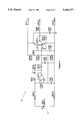
- FIG. 1 is a block diagram of the preferred embodiment of the flash intensity self monitoring system of the present invention
- FIG. 2 is a perspective view of the flash tube housing of the preferred embodiment
- FIG. 3 is a sectional view of the flash tube housing of FIG. 2;
- FIG. 4 is an electrical schematic of the optic board of the present invention.
- FIG. 5A is a timing diagram illustrating flash output v. time (in mS) for the flash tube
- FIG. 5B is the timing diagram for the binary signal from the optic board v. time (in mS);
- FIG. 6 is a perspective view of the major components of the automatic incandescent lamp monitoring system of the present invention.
- FIG. 7 is a block diagram of the lamp monitoring module of FIG. 6.
- flash intensity self monitoring system 11 includes an anti-collision light flash tube 13 (such as a made by Grimes, Hella and Flight Components), a light pipe 15, a photodiode 17, an optic board 19 (for the integration and conversion of analog electric signals toa digital time function), and a microcontroller 21.
- Light pipe 15 is, preferably, made of pyrex or other suitable light transmitting material. For the reasons set forth below, each end of light pipe 15 is hemispheric.
- the photodiode 17 is a human eye spectral response photodiode.
- Unit 25 includes an external housing 27, an internal housing 29, a fuselage mounting plate 31, and a glass flash tube cover 33.
- External housing 27 includes a flash tube unit mounting plate 35, and a gasket 37.
- the flash tube unit includes a mounting plate 39, a shield 41, conventional mechanical apparatus (not shown) for attaching cover 33 and conventional flash tube electrical connectors (alsonot shown).
- Flash tube mounting plate 35 includes an opening 43 (see FIG. 3) for supporting light pipe adaptor 45.
- Plate 31 includes a plurality of mounting holes, such as illustrated at 47, to secure unit 25 to the fuselage of an aircraft, and an opening (not shown) for supporting the sensor portion of photodiode 17 within housing 27 and beneath light pipe 15. Diode 17 does not have to be aligned with light pipe 15.
- Housing 29 supports optic board 19 and MPU board 51 (which includes microcontroller 21), circuit board 53 (of conventional design, for energizing flash tube 13), and conventional electric connector 55.
- Light pipe 15 is positioned laterally from flash tube 13 and photodiode 17 is positioned below plate 35 a distance sufficient to prevent photodiode 17 from being adversely affected by the intense heat generated by flash tube 13.
- the end of light pipe 15 exposed to flash tube 13 is rounded so that there is no alignment requirement whenit is screwed into place.
- the opposite end is also rounded to provide diffused light. The use of such diffused light attenuates the intensity ofthe light from flash tube 13 on photodiode 17, to a level below that which would overdrive or saturate photodiode 17.
- optic board 19 and MPU board 51 could, as those skilled in the art will appreciate, take a number of forms.
- optic board 19 is powered from the regulated +15 volts coming in through pin 1 of J301.
- Resistors R306, R307 and R308 are used to create a reference voltage of 5 volts and a bias voltage of 3 volts.
- the 3 volt bias voltage is applied across photodiode 17 by op amp Bof U301. This bias voltage is necessary to speed up the response time of photodiode 17.
- Potentiometer R304 is used to adjust the gain of op amp B of U301. Due to normal manufacturing tolerances, there will be variations in the optical light path between flash tube 13 and photodiode 17.
- Gain potentiometer R304 is used to calibrate theoptic board and to correct for any differences in the optical path.
- Resistor R303 and capacitor C301 form the analog integration network.
- Op amp A of U301 wired as an comparator to the 5 volt reference, changes this analog signal from C301 to a time function binary signal which is output through R305. This signal goes off the board through pin 2 of J301 and goes directly to microcontroller 21.
- flash tube 13 is energized via conventional electronics such as located on board 53 (not shown).
- a portion of the light emitted from each flash is transmitted, via light pipe 15, to photodiode 17 which, in turn, sends an analog signal to optics board 19.
- the effective intensity of a strobe light is defined as an integral of the instantaneous intensitytaken over the flash duration.
- the analog signal from photodiode 17 is integrated and converted into a digital time function. Specifically, the analog signal is integrated by optic board 19 into a binary function in which the time duration of the binary signal represents the effective intensity of the flash.
- Microcontroller 21 samples the binary signal after each flash at a predetermined point (as indicated in FIG. 5B).
- microcontroller 21 If the flash intensity is above the acceptable intensity (e.g., at or above 400 candela), microcontroller 21 will see a binary 1. If the flash intensity falls belowthe required minimum, microcontroller 21 will see a binary 0. Repeated flashes (e.g. 250; 50 flashes per minute for 5 minutes) at output levels below the predetermined minimum will cause microcontroller to send a faultsignal indicating that flash tube 13 should be replaced.
- the acceptable intensity e.g., at or above 400 candela
- System 71 includes a plurality of approach lamps 73 (typically PAR-56 or PAR-38 lamps), each of which includes an optical pickup bezel 75, fiber optic line 77, and monitor module 79.
- Bezel 75 is made of pyrex or other similar material to pick up light from around the entire perimeter of lamp 73, without degrading or interfering with the lamp's projected beam path. By internal reflection a portion of the light picked up is directed to pick up point 80.
- Line 77 includes standard couplers 81, 83 and exposed fiber ends 85, 87. Coupler 81 mates with threaded adaptor 89 to position end 85 within bezel 75 at pick-up point 80. Coupler 83 mates with threaded adaptor 91 to position tip 87 within the housing of monitor module 79.
- the basic internal components of module 79 include a photodiode 93, a signal conditioning stage 95, and A/D converter 97, a power line transceiver 99, and a microcontroller 101.
- Photodiode 93 is a human eye spectral response photodiode.
- Signal conditioning stage 95 amplifies and conditions the analog signal from photodiode 93 so that it fits the input range of A/D converter 97.
- the conditioning includes calibration and temperature compensation circuits.
- A/D converter 97 may be a serial output 5.6.sup. ⁇ s 12-bit A/D convertersuch as the Maxim Max 170.
- A/D converter 97 only reads the signal from conditioning stage 95 in response to a command from microcontroller 101.
- Transreceiver 99 may be a commercial grade FM line transmitter/receiver unit, which includes a transformer to electronically couple the componentsof module 79 to the power line (not shown) for lamp 73. This permits the lamp monitoring system to send the digital information along the power lines which have already been put in place to run the lamps being monitored.
- MPU 101 is, preferably, a single chip programmable microcontroller such as a PIC16C56.
- each MPU 101 is programmed to respond only to a unique poll command.
- a master computer (not shown) at a remote location monitors all lamps in the array by polling each lamp (in sequence or as otherwise directed).
- MPU 101 receives its unique poll command, via the associated lamp's power line, it commands A/D converter 97 to function.
- A/D converter 97 reads the voltage signal from conditioner 95, converts this signal to a 12 bit digital word, which is then output to transceiver 99.
- Transceiver 99 then sends the digital signal over the power line of lamp 73 to the master computer which processes the signal with a lookup table or equivalent to determine if thebrightness of lamp 73 is within range.
Abstract
Flash tube and lamp monitoring systems. The flash tube intensity monitoring system includes: a human eye spectral response photodiode for producing analog signals, each of which is directly proportional to the intensity of each flash from the flash tube; electronics for converting each of the analog signals to a digital time function proportional to the intensity of the corresponding flash; and electronics, including a microprocessor, for monitoring each of the digital time functions, for flagging those time functions which are below a preselected minimum, and for sending a fault signal when a preselected number of consecutive time functions are below the pre-selected minimum. The monitoring system and flash tube are, preferably, incorporated into single unit for easy installation in the fuselage of an aircraft. The lamp monitoring system includes: a light pickup; a photodiode for producing an analog signal which is directly proportional to the intensity of the lamp being monitored; a line transceiver; an A/D converter; and a microcontroller. The microcontroller, which has a unique identification code, sends a command to the A/D converter only upon receipt of the matching poll command.
Description
This invention relates to systems for the automatic self monitoring of the intensity of illumination sources, such as aircraft anti-collision flash tubes and incandescent lamps used in airport approach lighting systems, and the sending of a fault signal to a monitoring system when the illumination falls below a predetermined level.
Xenon flash tubes are mandated for use as anti-collision lights on aircraft. These tubes produce sudden, brilliant flashes of light that are much more conspicuous than other light sources. Current FAA (i.e., Federal Aviation Administration) mandated airworthiness standards require that such flash tubes have an effective intensity of 400 candela when viewed within 5 degrees of horizontal for aircraft certified after 1977. For aircraft certified before 1977 the requirement is 100 candela.
In a new strobe unit, the intensity of the xenon flash tube will meet or exceed FAA brightness standards. However, the intensity significantly degrades with use, long prior to actual tube failure. See: B. W. Henderson, "FAA: Aircraft Strobe Lights May Fall Short of Standards" Aviation Week & Space Technology, pp 42-43, Sep. 14, 1992; and V. M. Gardov, et al., "Theory of Powerful Nonsteady Xenon Discharge Taking Vaporization of Its Stabilizing Walls Into Account" translated from Teplofizika Vysokikh Temperatur, Vol. 19, No. 1., pp. 28-35, January-February, 1981. The result is that most flash tubes continue to work long after they have degraded below FAA minimum brightness requirements. An FAA survey showed that airlines generally rely on the technical manuals from the strobe light suppliers, which do not recommend checking brightness or regularly replacing xenon flash tubes. See Henderson, supra.
Strotek (Carson City, Nev.) claims to have developed a portable optical measuring system which can check flash tube intensity from outside the aircraft while they are on the ground. However, such a system is not an automatic self monitoring system, as disclosed and claimed herein.
U.S. Pat. No. 3,366,835 to H. L. Morris discloses a circuit for indicating a flash tube failure when the monitored tube is located where it is not readily visible to the operator. The failure indicator includes a light conducting plastic rod 48 which extends from the vicinity of the flash tube 14 to a photocell 49. Photocell 49 is part of a circuit including relay 53, capacitor 54, contacts 55 and warning light 56. If the flash tube fails to light for a predetermined period, capacitor 54 does not recharge and relay 53 is de-energized. Contact 55 then closes and the indicator light 56 comes on.
A similar problem is encountered with airport runway approach lighting systems. PAR-38 and PAR-56 tungsten-halogen incandescent lamps are currently used. The FAA requires that all lamps in a given system be of even brightness. However, the PAR lamps age with use, with the unacceptable result that some lamps appear dimmer than others.
A common solution to the foregoing problem with approach lighting systems is, per FAA regulations, to replace all the lamps in the system on a periodic basis (e.g., every 400 hours at major airports) even though many of the lamps still meet illumination requirements. Alternately, indirect monitoring systems are used which are subject to false indications caused by variances in loop current and lamp impedance, aging effects and by shorting devices intended to protect the system when a lamp fails. U.S. Pat. No. 5,105,124 to K. Futsuhara, et al., discloses a system in which a feedback signal consisting of a unique frequency for each lamp flows through the lamp circuit. Thus, any failed lamp can be detected by checking this feedback signal. Unfortunately, this system does not detect lamps which have not failed, but are below FAA brightness requirements.
Numerous other lamp failure indicators are disclosed in the prior art. See, for instance: U.S. Pat. No. 3,541,504 to R. H. Bush, which is described as a vehicle burn-out indicator; U.S. Pat. No. 3,588,816 to R. H. Himes; U.S. Pat. No. 3,624,629 to C. A. Donaldson; U.S. Pat. No. 4,572,987 to D. M. Embrey, et al.; and U.S. Pat. No. 4,376,910 to J.P. Pieslier.
In view of the foregoing, it is an object of the present invention to provide systems for the continuous monitoring of flash tubes and continuous illumination sources, which systems provide a fault signal or other indication when the intensity of the source being monitored falls below a predetermined (sometimes mandated) value (e.g., a minimum set by a regulatory agency such as the FAA).
It is also an objection of the invention to improve airport runway approach lighting by providing a system capable of monitoring, either continuously or on command, each of the lamps used therein and providing a fault signal or other indication when the intensity falls below the required minimum (even though the lamp has not failed).
It is a further object of the invention to use the existing runway approach lamp power grid to avoid the requirement for any additional wiring.
It is another object of the invention to provide a system which can be used to monitor both high intensity constant current and medium intensity constant voltage runway approach lighting systems.
The foregoing improves both aircraft and runway safety and, at least in the case of runway approach lights, reduces the unnecessary replacement of lights in those systems where, for lack of applicant's monitoring system, all lamps are replaced on a periodic basis regardless of their individual intensities. In addition, the monitoring capability can statistically record average bulb lifetimes, thus allowing an accurate forecasting of bulb purchases.
A flash tube intensity monitoring system including: a human eye spectral response photodiode for producing analog signals, each of which is directly proportional to the intensity of each flash from the flash tube; electronics for converting each of the analog signals to a digital time function proportional to the intensity of the corresponding flash; and electronics, including a microprocessor, for monitoring each of the digital time functions, for flagging those time functions which are below a preselected minimum, and for sending a fault signal when a preselected number of consecutive time functions are below the pre-selected minimum. The monitoring system and flash tube are, preferably, incorporated into single unit for easy installation in the fuselage of an aircraft. The unit includes structure, interposed between the flash tube and the photodiode for at least partially blocking heat from the flash tube from reaching the photodiode. The unit also includes a light pipe which samples the light from the flash tube and transmits this sampled light to the photodiode. The electronics for converting the analog signals includes an analog integration circuit and a calibration circuit. The microprocessor looks for variations in flash intensity as seen by the photodiode.
The lamp monitoring system, for incandescent or other continuous light sources, includes a light pickup, a photodiode for producing an analog signal which is directly proportional to the intensity of the lamp being monitored, a line transceiver for sending and receiving digital data and instructions over the lamp's power line, means for converting the analog signals to a digital function proportional to the intensity of the lamp, and a microcontroller connected to the line transceiver and the converting means. The converting means is connected to the photodiode and the line transceiver. The microcontroller includes a unique identification code and is adapted to receive a poll command over the power line, whereby when the microcontroller receives the poll command which matches the unique identification code it sends a command to the converting means and the converting means converts the analog signals to said digital function. The monitoring system also includes apparatus for amplifying and conditioning the analog signals from the photodiode so as to fit the input range of the converting means (preferably an A/D chip). The monitoring system further includes an optical pickup bezel for collecting visible light from the lamp, which bezel contacts at least a portion of the perimeter of the lamp without degrading or interfering with the lamp's projected beam path. The monitoring system also further includes an optical coupling which separates the photodiode, the line transceiver, A/D chip, and microcontroller from the intense heat generated by the lamp.
FIG. 1 is a block diagram of the preferred embodiment of the flash intensity self monitoring system of the present invention;
FIG. 2 is a perspective view of the flash tube housing of the preferred embodiment;
FIG. 3 is a sectional view of the flash tube housing of FIG. 2;
FIG. 4 is an electrical schematic of the optic board of the present invention;
FIG. 5A is a timing diagram illustrating flash output v. time (in mS) for the flash tube;
FIG. 5B is the timing diagram for the binary signal from the optic board v. time (in mS);
FIG. 6 is a perspective view of the major components of the automatic incandescent lamp monitoring system of the present invention; and
FIG. 7 is a block diagram of the lamp monitoring module of FIG. 6.
With referenced to FIG. 1, flash intensity self monitoring system 11 includes an anti-collision light flash tube 13 (such as a made by Grimes, Hella and Flight Components), a light pipe 15, a photodiode 17, an optic board 19 (for the integration and conversion of analog electric signals toa digital time function), and a microcontroller 21. Light pipe 15 is, preferably, made of pyrex or other suitable light transmitting material. For the reasons set forth below, each end of light pipe 15 is hemispheric.For aircraft anti-collision flash tubes, the photodiode 17 is a human eye spectral response photodiode.
The above-identified components are housed in anti-collision light unit 25,as illustrated in FIGS. 2 and 3. Unit 25 includes an external housing 27, an internal housing 29, a fuselage mounting plate 31, and a glass flash tube cover 33. External housing 27 includes a flash tube unit mounting plate 35, and a gasket 37. The flash tube unit includes a mounting plate 39, a shield 41, conventional mechanical apparatus (not shown) for attaching cover 33 and conventional flash tube electrical connectors (alsonot shown). Flash tube mounting plate 35 includes an opening 43 (see FIG. 3) for supporting light pipe adaptor 45. Plate 31 includes a plurality of mounting holes, such as illustrated at 47, to secure unit 25 to the fuselage of an aircraft, and an opening (not shown) for supporting the sensor portion of photodiode 17 within housing 27 and beneath light pipe 15. Diode 17 does not have to be aligned with light pipe 15. Housing 29 supports optic board 19 and MPU board 51 (which includes microcontroller 21), circuit board 53 (of conventional design, for energizing flash tube 13), and conventional electric connector 55.
Electrical wiring (partially shown) interconnects the various boards and electrical components. Light pipe 15 is positioned laterally from flash tube 13 and photodiode 17 is positioned below plate 35 a distance sufficient to prevent photodiode 17 from being adversely affected by the intense heat generated by flash tube 13. The end of light pipe 15 exposed to flash tube 13 is rounded so that there is no alignment requirement whenit is screwed into place. The opposite end is also rounded to provide diffused light. The use of such diffused light attenuates the intensity ofthe light from flash tube 13 on photodiode 17, to a level below that which would overdrive or saturate photodiode 17.
The design of optic board 19 and MPU board 51 could, as those skilled in the art will appreciate, take a number of forms. As illustrated schematically in FIG. 4, optic board 19 is powered from the regulated +15 volts coming in through pin 1 of J301. Resistors R306, R307 and R308 are used to create a reference voltage of 5 volts and a bias voltage of 3 volts. The 3 volt bias voltage is applied across photodiode 17 by op amp Bof U301. This bias voltage is necessary to speed up the response time of photodiode 17. Potentiometer R304 is used to adjust the gain of op amp B of U301. Due to normal manufacturing tolerances, there will be variations in the optical light path between flash tube 13 and photodiode 17. This will cause variations in the light intensity of the strobe flash as seen by the photodiode. There will also be slight variations in the photodiode's sensitivity. Gain potentiometer R304 is used to calibrate theoptic board and to correct for any differences in the optical path. Resistor R303 and capacitor C301 form the analog integration network. Op amp A of U301, wired as an comparator to the 5 volt reference, changes this analog signal from C301 to a time function binary signal which is output through R305. This signal goes off the board through pin 2 of J301 and goes directly to microcontroller 21.
In operation, flash tube 13 is energized via conventional electronics such as located on board 53 (not shown). A portion of the light emitted from each flash is transmitted, via light pipe 15, to photodiode 17 which, in turn, sends an analog signal to optics board 19. The effective intensity of a strobe light is defined as an integral of the instantaneous intensitytaken over the flash duration. With reference to FIGS. 5A and 5B, the analog signal from photodiode 17 is integrated and converted into a digital time function. Specifically, the analog signal is integrated by optic board 19 into a binary function in which the time duration of the binary signal represents the effective intensity of the flash. Microcontroller 21 samples the binary signal after each flash at a predetermined point (as indicated in FIG. 5B). If the flash intensity is above the acceptable intensity (e.g., at or above 400 candela), microcontroller 21 will see a binary 1. If the flash intensity falls belowthe required minimum, microcontroller 21 will see a binary 0. Repeated flashes (e.g. 250; 50 flashes per minute for 5 minutes) at output levels below the predetermined minimum will cause microcontroller to send a faultsignal indicating that flash tube 13 should be replaced.
With reference to FIG. 6, the major components of an automatic incandescentlamp monitoring system 71 for, for instance, airport runway approach lighting systems, is illustrated. System 71 includes a plurality of approach lamps 73 (typically PAR-56 or PAR-38 lamps), each of which includes an optical pickup bezel 75, fiber optic line 77, and monitor module 79. Bezel 75 is made of pyrex or other similar material to pick up light from around the entire perimeter of lamp 73, without degrading or interfering with the lamp's projected beam path. By internal reflection a portion of the light picked up is directed to pick up point 80. Line 77 includes standard couplers 81, 83 and exposed fiber ends 85, 87. Coupler 81 mates with threaded adaptor 89 to position end 85 within bezel 75 at pick-up point 80. Coupler 83 mates with threaded adaptor 91 to position tip 87 within the housing of monitor module 79.
The basic internal components of module 79, which are illustrated in FIG. 7, include a photodiode 93, a signal conditioning stage 95, and A/D converter 97, a power line transceiver 99, and a microcontroller 101. Photodiode 93 is a human eye spectral response photodiode. Signal conditioning stage 95 amplifies and conditions the analog signal from photodiode 93 so that it fits the input range of A/D converter 97. The conditioning includes calibration and temperature compensation circuits. A/D converter 97 may be a serial output 5.6.sup.μs 12-bit A/D convertersuch as the Maxim Max 170. A/D converter 97 only reads the signal from conditioning stage 95 in response to a command from microcontroller 101. Transreceiver 99 may be a commercial grade FM line transmitter/receiver unit, which includes a transformer to electronically couple the componentsof module 79 to the power line (not shown) for lamp 73. This permits the lamp monitoring system to send the digital information along the power lines which have already been put in place to run the lamps being monitored. Finally, MPU 101 is, preferably, a single chip programmable microcontroller such as a PIC16C56.
In operation, each MPU 101 is programmed to respond only to a unique poll command. A master computer (not shown) at a remote location monitors all lamps in the array by polling each lamp (in sequence or as otherwise directed). When MPU 101 receives its unique poll command, via the associated lamp's power line, it commands A/D converter 97 to function. Inresponse to this command, A/D converter 97 reads the voltage signal from conditioner 95, converts this signal to a 12 bit digital word, which is then output to transceiver 99. Transceiver 99 then sends the digital signal over the power line of lamp 73 to the master computer which processes the signal with a lookup table or equivalent to determine if thebrightness of lamp 73 is within range.
Whereas the drawings and accompanying description have shown and described the preferred embodiment of the present invention, it should be apparent to those skilled in the art that various changes may be made in the form of the invention without affecting the scope thereof.
Claims (18)
1. A flash tube intensity monitoring system, said system comprising:
a. a human eye spectral response photodiode for producing analog signals, each of said analog signals being directly proportional to the intensity of each flash from said flash tube;
b. means for converting each of said analog signals to a digital time function proportional to said intensity of the corresponding one of said flash; and
c. means for monitoring each of said digital time functions, for flagging those of said time functions which are below a preselected minimum and for sending a fault signal when a preselected number of consecutive time functions are below said pre-selected minimum.
2. The monitoring system as set forth in claim 1, further including means, interposed between said flash tube and said photodiode, for at least partially blocking infrared radiation from reaching said photodiode.
3. The monitoring system as set forth in claim 2, wherein said means for blocking is a light pipe which filters infrared radiation.
4. The monitoring system as set forth in claim 1, wherein said means for converting said analog signals includes analog integration on circuit.
5. The monitoring system as set forth in claim 4, wherein said analog integration circuit includes a resistor, a capacitor and an operational amplifier.
6. The monitoring system as set forth in claim 1, wherein said means for converting includes means to compensate for variations in said flash intensity from said flash tube as seen by said photodiode.
7. The monitoring system as set forth in claim 1, wherein said means for monitoring includes a microcontroller.
8. An automated anticollision light monitoring unit for aircraft, said unit comprising:
a. a housing;
b. a flash tube supported by said housing;
c. a human eye spectral response photodiode disposed relative to said housing, said diode producing an electronic signal, said signal being proportional to the intensity of the corresponding flash from said flash tube;
d. means for converting said electronic signal to a digital time function proportional to said intensity of said corresponding flash; and
e. means for monitoring said digital function and for generating a fault signal when said digital function is below a preselected value for a preselected period of time, said converting means interconnecting said monitoring means and said photodiode.
9. The unit as set forth in claim 8, further including means for shielding said photodiode from the heat generated by said flash tube.
10. The unit as set forth in claim 9, further including means, interposed between said flash tube and said photodiode for at least partially blocking infrared radiation from reaching said photodiode.
11. A monitoring system for a lamp such as used in an airport approach array, said lamp having a power line, said system comprising:
a. a light pickup positionable relative to said lamp to pick up a portion of the light emitted by said lamp;
b. a human eye spectral response photodiode for producing an electronic signal which is proportional to the intensity of visible light emitted by said lamp;
c. a line transceiver for sending and receiving digital data and instructions over said lamp power line;
d. means for converting said electronic signal to a digital function proportional to the intensity of said lamp, said converting means connected to said photodiode and said line transceiver; and
e. a microcontroller connected to said line transceiver and said converting means, said microcontroller including a unique identification code and adapted to receive a poll command over said power line, whereby when said microcontroller receives a poll command which matches said unique identification code, said microcontroller sends a command to said converting means and said converting means converts said electronic signal to said digital function.
12. The monitoring system as set forth in claim 11, further including means for amplifying and conditioning said electronic signal from said photodiode so as to fit the input range of said converting means.
13. The monitoring system as set forth in claim 12, wherein said converting means is an A/D chip.
14. The monitoring system as set forth in claim 11, further including an optical pickup bezel for collecting visible light from said lamp for transmission to said photodiode.
15. The monitoring system as set forth in claim 14, wherein said bezel contacts at least a portion of the perimeter of said lamp without degrading or interfering with said lamp's projected beam path.
16. The monitoring system as set forth in claim 14, further including optical coupling means for coupling said bezel to said photodiode.
17. The monitoring system as set forth in claim 16, wherein said optical coupling means separates said photodiode, said line transceiver, said converting means, and said microcontroller from the intense heat generated by said lamp.
18. The monitoring system as set forth in claim 17, wherein said optical coupling means is a fiber optic cable.
Priority Applications (3)
| Application Number | Priority Date | Filing Date | Title |
|---|---|---|---|
| US08/173,087 US5446277A (en) | 1993-12-27 | 1993-12-27 | Automated lamp monitoring system for comparing light intensities with a preselected valve |
| AU14420/95A AU1442095A (en) | 1993-12-27 | 1994-12-21 | Biologically active agent encapsulated in biodegradable starch/polymer matrices |
| PCT/US1994/014728 WO1995017815A1 (en) | 1993-12-27 | 1994-12-21 | Biologically active agent encapsulated in biodegradable starch/polymer matrices |
Applications Claiming Priority (1)
| Application Number | Priority Date | Filing Date | Title |
|---|---|---|---|
| US08/173,087 US5446277A (en) | 1993-12-27 | 1993-12-27 | Automated lamp monitoring system for comparing light intensities with a preselected valve |
Publications (1)
| Publication Number | Publication Date |
|---|---|
| US5446277A true US5446277A (en) | 1995-08-29 |
Family
ID=22630489
Family Applications (1)
| Application Number | Title | Priority Date | Filing Date |
|---|---|---|---|
| US08/173,087 Expired - Lifetime US5446277A (en) | 1993-12-27 | 1993-12-27 | Automated lamp monitoring system for comparing light intensities with a preselected valve |
Country Status (1)
| Country | Link |
|---|---|
| US (1) | US5446277A (en) |
Cited By (13)
| Publication number | Priority date | Publication date | Assignee | Title |
|---|---|---|---|---|
| US5654794A (en) * | 1995-01-13 | 1997-08-05 | Devore Aviation | Portable light intensity monitoring systems |
| US6278382B1 (en) | 1998-11-06 | 2001-08-21 | Demarco Ralph Anthony | Recognition/anti-collision light for aircraft |
| US6436299B1 (en) | 1999-06-21 | 2002-08-20 | Amway Corporation | Water treatment system with an inductively coupled ballast |
| US20030071991A1 (en) * | 2001-10-11 | 2003-04-17 | Ulrich Sander | Light source for illumination in an optical viewing device |
| US6554441B2 (en) * | 2001-08-31 | 2003-04-29 | Aqua Signal Aktiengesellschaft Spezialleuchtenfabrik | Lighting installation, in particular as a danger light, and wind rotor installation with lighting installation |
| US6673250B2 (en) | 1999-06-21 | 2004-01-06 | Access Business Group International Llc | Radio frequency identification system for a fluid treatment system |
| US20060017583A1 (en) * | 2004-07-26 | 2006-01-26 | Davenport David M | Apparatus and method for monitoring the output of a warning or indicator light |
| US7068188B1 (en) | 2004-06-08 | 2006-06-27 | Controlled Power Company | Runway approach lighting system and method |
| US7088263B1 (en) | 2004-06-08 | 2006-08-08 | Controlled Power Company | Runway approach lighting system and method |
| US20070001833A1 (en) * | 2005-06-30 | 2007-01-04 | Streetlight Intelligence, Inc. | Compensation for photo sensor |
| US20080030723A1 (en) * | 2006-07-07 | 2008-02-07 | Airbus France | Process and device for monitoring the illumination of lamp bulbs |
| US7382454B1 (en) * | 2006-09-24 | 2008-06-03 | Carl Anthony Turner | System and method for optically assessing lamp condition |
| EP4043348A1 (en) * | 2021-02-12 | 2022-08-17 | Goodrich Lighting Systems GmbH & Co. KG | Exterior aircraft light and aircraft comprising an exterior aircraft light |
Citations (13)
| Publication number | Priority date | Publication date | Assignee | Title |
|---|---|---|---|---|
| US3366835A (en) * | 1967-02-09 | 1968-01-30 | Harold L. Morris | Circuits for energizing a flashtube |
| US3541504A (en) * | 1967-06-01 | 1970-11-17 | Howard R Bush | Vehicle lamp failure indicator |
| US3588816A (en) * | 1968-07-03 | 1971-06-28 | Raymond H Himes | Monitor system for vehicle lights |
| US3609450A (en) * | 1969-02-20 | 1971-09-28 | Lindor Electronics Inc | Automatic headlight-washing system |
| US3624629A (en) * | 1968-10-30 | 1971-11-30 | Charles A Donaldson | Warning system for warning of defective headlights, taillights and the like on motor vehicles, aircraft, marine craft and the like |
| US3634694A (en) * | 1969-03-18 | 1972-01-11 | Us Navy | Programmed-response spectral scanning telephotometer system |
| US4227808A (en) * | 1977-12-29 | 1980-10-14 | Minolta Camera Kabushiki Kaisha | Digital light measuring device |
| US4376910A (en) * | 1979-07-16 | 1983-03-15 | Jeumont-Schneider | Power supply and control device for the proper operation of a railway traffic light |
| US4572987A (en) * | 1983-03-11 | 1986-02-25 | Ab Electronic Components Limited | Lamp monitoring circuit |
| US4982139A (en) * | 1989-04-03 | 1991-01-01 | At&T Bell Laboratories | Method and apparatus for controlling light intensity |
| US4994845A (en) * | 1985-08-07 | 1991-02-19 | Minolta Camera Kabushiki Kaisha | Light measuring device |
| US5105124A (en) * | 1988-03-25 | 1992-04-14 | Nippon Signal Co., Ltd. | Lamp failure detecting device |
| US5235252A (en) * | 1991-12-31 | 1993-08-10 | Blake Frederick H | Fiber-optic anti-cycling device for street lamps |
-
1993
- 1993-12-27 US US08/173,087 patent/US5446277A/en not_active Expired - Lifetime
Patent Citations (13)
| Publication number | Priority date | Publication date | Assignee | Title |
|---|---|---|---|---|
| US3366835A (en) * | 1967-02-09 | 1968-01-30 | Harold L. Morris | Circuits for energizing a flashtube |
| US3541504A (en) * | 1967-06-01 | 1970-11-17 | Howard R Bush | Vehicle lamp failure indicator |
| US3588816A (en) * | 1968-07-03 | 1971-06-28 | Raymond H Himes | Monitor system for vehicle lights |
| US3624629A (en) * | 1968-10-30 | 1971-11-30 | Charles A Donaldson | Warning system for warning of defective headlights, taillights and the like on motor vehicles, aircraft, marine craft and the like |
| US3609450A (en) * | 1969-02-20 | 1971-09-28 | Lindor Electronics Inc | Automatic headlight-washing system |
| US3634694A (en) * | 1969-03-18 | 1972-01-11 | Us Navy | Programmed-response spectral scanning telephotometer system |
| US4227808A (en) * | 1977-12-29 | 1980-10-14 | Minolta Camera Kabushiki Kaisha | Digital light measuring device |
| US4376910A (en) * | 1979-07-16 | 1983-03-15 | Jeumont-Schneider | Power supply and control device for the proper operation of a railway traffic light |
| US4572987A (en) * | 1983-03-11 | 1986-02-25 | Ab Electronic Components Limited | Lamp monitoring circuit |
| US4994845A (en) * | 1985-08-07 | 1991-02-19 | Minolta Camera Kabushiki Kaisha | Light measuring device |
| US5105124A (en) * | 1988-03-25 | 1992-04-14 | Nippon Signal Co., Ltd. | Lamp failure detecting device |
| US4982139A (en) * | 1989-04-03 | 1991-01-01 | At&T Bell Laboratories | Method and apparatus for controlling light intensity |
| US5235252A (en) * | 1991-12-31 | 1993-08-10 | Blake Frederick H | Fiber-optic anti-cycling device for street lamps |
Non-Patent Citations (4)
| Title |
|---|
| Gradov, V. M., et al., "Theory of Powerful Nonsteady Xenon Discharge Taking Vaporization of its Stabilizing Walls Into Account", translated from Teplofizika Vysokikh Temperatur, vol. 19, No. 1, pp. 28-35, Jan.-Feb. 1981. |
| Gradov, V. M., et al., Theory of Powerful Nonsteady Xenon Discharge Taking Vaporization of its Stabilizing Walls Into Account , translated from Teplofizika Vysokikh Temperatur, vol. 19, No. 1, pp. 28 35, Jan. Feb. 1981. * |
| Henderson, Breck W., "FAA: Aircraft Strobe Lights May Fall Short of Standards", Aviation Week & Space Technology, pp. 42-43, Sep. 14, 1992. |
| Henderson, Breck W., FAA: Aircraft Strobe Lights May Fall Short of Standards , Aviation Week & Space Technology, pp. 42 43, Sep. 14, 1992. * |
Cited By (23)
| Publication number | Priority date | Publication date | Assignee | Title |
|---|---|---|---|---|
| US5654794A (en) * | 1995-01-13 | 1997-08-05 | Devore Aviation | Portable light intensity monitoring systems |
| US6989768B2 (en) | 1998-11-06 | 2006-01-24 | Goodrich Corporation | Recognition/anti-collision light for aircraft |
| US6278382B1 (en) | 1998-11-06 | 2001-08-21 | Demarco Ralph Anthony | Recognition/anti-collision light for aircraft |
| US6642856B2 (en) * | 1998-11-06 | 2003-11-04 | Goodrich Lighting Systems, Inc. | Recognition/anti-collision light for aircraft |
| US20040075575A1 (en) * | 1998-11-06 | 2004-04-22 | Demarco Ralph Anthony | Recognition/anti-collision light for aircraft |
| EP1352829A3 (en) * | 1998-11-06 | 2004-06-16 | Goodrich Lighting Systems, Inc. | Recognition/anti-collision light for aircraft |
| US6436299B1 (en) | 1999-06-21 | 2002-08-20 | Amway Corporation | Water treatment system with an inductively coupled ballast |
| US6673250B2 (en) | 1999-06-21 | 2004-01-06 | Access Business Group International Llc | Radio frequency identification system for a fluid treatment system |
| US6554441B2 (en) * | 2001-08-31 | 2003-04-29 | Aqua Signal Aktiengesellschaft Spezialleuchtenfabrik | Lighting installation, in particular as a danger light, and wind rotor installation with lighting installation |
| US20030071991A1 (en) * | 2001-10-11 | 2003-04-17 | Ulrich Sander | Light source for illumination in an optical viewing device |
| US6909499B2 (en) * | 2001-10-11 | 2005-06-21 | Leica Microsystems (Schweiz) Ag | Light source for illumination in an optical viewing device |
| US7068188B1 (en) | 2004-06-08 | 2006-06-27 | Controlled Power Company | Runway approach lighting system and method |
| US7088263B1 (en) | 2004-06-08 | 2006-08-08 | Controlled Power Company | Runway approach lighting system and method |
| US20060017583A1 (en) * | 2004-07-26 | 2006-01-26 | Davenport David M | Apparatus and method for monitoring the output of a warning or indicator light |
| US7123165B2 (en) * | 2004-07-26 | 2006-10-17 | General Electric Company | Apparatus and method for monitoring the output of a warning or indicator light |
| US7608815B2 (en) | 2005-06-30 | 2009-10-27 | Streetlight Intelligence, Inc. | Photo detector with compensated output and method involving same |
| US20070001833A1 (en) * | 2005-06-30 | 2007-01-04 | Streetlight Intelligence, Inc. | Compensation for photo sensor |
| US20080030723A1 (en) * | 2006-07-07 | 2008-02-07 | Airbus France | Process and device for monitoring the illumination of lamp bulbs |
| US7742161B2 (en) * | 2006-07-07 | 2010-06-22 | Airbus France | Process and device for monitoring the illumination of lamp bulbs |
| US7382454B1 (en) * | 2006-09-24 | 2008-06-03 | Carl Anthony Turner | System and method for optically assessing lamp condition |
| EP4043348A1 (en) * | 2021-02-12 | 2022-08-17 | Goodrich Lighting Systems GmbH & Co. KG | Exterior aircraft light and aircraft comprising an exterior aircraft light |
| US20220258881A1 (en) * | 2021-02-12 | 2022-08-18 | Goodrich Lighting Systems GmbH & Co. KG | Exterior aircraft light and aircraft comprising an exterior aircraft light |
| US11884419B2 (en) * | 2021-02-12 | 2024-01-30 | Goodrich Lighting Systems GmbH & Co. KG | Exterior aircraft light and aircraft comprising an exterior aircraft light |
Similar Documents
| Publication | Publication Date | Title |
|---|---|---|
| US5446277A (en) | Automated lamp monitoring system for comparing light intensities with a preselected valve | |
| US3752978A (en) | Photoelectric intrusion detector | |
| US6642856B2 (en) | Recognition/anti-collision light for aircraft | |
| US3882477A (en) | Smoke and heat detector incorporating an improved smoke chamber | |
| US4870394A (en) | Smoke detector with improved testing | |
| US5115126A (en) | Means for checking endoscope equipment | |
| US7956329B2 (en) | Flame detector and a method | |
| US5399875A (en) | Liquid gauging apparatus and remote sensor interrogation | |
| WO2005107105A1 (en) | Optical transceiver and host adapter with memory mapped monitoring circuitry | |
| US4937461A (en) | Transmissometer having solid state light source | |
| US5334972A (en) | Infrared intruder-detection system | |
| US4728794A (en) | Radiation sensing arrangements | |
| US4987297A (en) | Method and apparatus for automatically reading a mechanical fluid meter | |
| US5053929A (en) | Device for illuminating a bundle of optical fibers | |
| US4333724A (en) | Photoelectric detector | |
| WO1997018483A1 (en) | Meter testing circuit | |
| US3411005A (en) | Compact infrared detector systems with regulated power supply | |
| US4288161A (en) | Optical probe for detecting transitory and repetitive light signals | |
| US20050156749A1 (en) | Remote lamp status display via fiber optic system | |
| JPH0827239B2 (en) | Lighting equipment | |
| JP2003202263A (en) | Unlighted street light detecting device | |
| US5654794A (en) | Portable light intensity monitoring systems | |
| AU705602B2 (en) | Meter testing circuit | |
| JP2980923B2 (en) | Reception level adjusting device for spatial transmission signal in fire alarm equipment | |
| JP2980924B2 (en) | Receiving angle adjusting device for spatial transmission signal in fire alarm system |
Legal Events
| Date | Code | Title | Description |
|---|---|---|---|
| AS | Assignment |
Owner name: DEVORE AVIATION CORPORATION OF AMERICA, NEW MEXICO Free format text: ASSIGNMENT OF ASSIGNORS INTEREST;ASSIGNOR:RUTTER, ROBERT E.;REEL/FRAME:006820/0271 Effective date: 19931222 |
|
| STCF | Information on status: patent grant |
Free format text: PATENTED CASE |
|
| REMI | Maintenance fee reminder mailed | ||
| FPAY | Fee payment |
Year of fee payment: 4 |
|
| SULP | Surcharge for late payment | ||
| FPAY | Fee payment |
Year of fee payment: 8 |
|
| FPAY | Fee payment |
Year of fee payment: 12 |