US5441399A - Method of removing stuck sprue and tool for removal therein - Google Patents
Method of removing stuck sprue and tool for removal therein Download PDFInfo
- Publication number
- US5441399A US5441399A US08/297,260 US29726094A US5441399A US 5441399 A US5441399 A US 5441399A US 29726094 A US29726094 A US 29726094A US 5441399 A US5441399 A US 5441399A
- Authority
- US
- United States
- Prior art keywords
- tool
- sprue
- stuck
- ejector
- removal
- Prior art date
- Legal status (The legal status is an assumption and is not a legal conclusion. Google has not performed a legal analysis and makes no representation as to the accuracy of the status listed.)
- Expired - Fee Related
Links
- 238000000034 method Methods 0.000 title abstract description 17
- 238000007373 indentation Methods 0.000 claims abstract description 6
- 238000001746 injection moulding Methods 0.000 claims abstract description 4
- 239000004020 conductor Substances 0.000 claims description 2
- 239000002184 metal Substances 0.000 claims 1
- 238000002844 melting Methods 0.000 abstract description 3
- 230000008018 melting Effects 0.000 abstract description 3
- 239000012778 molding material Substances 0.000 abstract 2
- 239000000463 material Substances 0.000 description 12
- 238000000465 moulding Methods 0.000 description 10
- 238000004519 manufacturing process Methods 0.000 description 4
- 238000010276 construction Methods 0.000 description 2
- 238000001816 cooling Methods 0.000 description 2
- 229910000831 Steel Inorganic materials 0.000 description 1
- 238000005520 cutting process Methods 0.000 description 1
- 230000007547 defect Effects 0.000 description 1
- 238000010438 heat treatment Methods 0.000 description 1
- 238000002347 injection Methods 0.000 description 1
- 239000007924 injection Substances 0.000 description 1
- 230000007257 malfunction Effects 0.000 description 1
- 239000012768 molten material Substances 0.000 description 1
- 238000010137 moulding (plastic) Methods 0.000 description 1
- 239000011435 rock Substances 0.000 description 1
- 239000007787 solid Substances 0.000 description 1
- 239000010959 steel Substances 0.000 description 1
Images


Classifications
-
- B—PERFORMING OPERATIONS; TRANSPORTING
- B29—WORKING OF PLASTICS; WORKING OF SUBSTANCES IN A PLASTIC STATE IN GENERAL
- B29C—SHAPING OR JOINING OF PLASTICS; SHAPING OF MATERIAL IN A PLASTIC STATE, NOT OTHERWISE PROVIDED FOR; AFTER-TREATMENT OF THE SHAPED PRODUCTS, e.g. REPAIRING
- B29C45/00—Injection moulding, i.e. forcing the required volume of moulding material through a nozzle into a closed mould; Apparatus therefor
- B29C45/17—Component parts, details or accessories; Auxiliary operations
- B29C45/1759—Removing sprues from sprue-channels
-
- Y—GENERAL TAGGING OF NEW TECHNOLOGICAL DEVELOPMENTS; GENERAL TAGGING OF CROSS-SECTIONAL TECHNOLOGIES SPANNING OVER SEVERAL SECTIONS OF THE IPC; TECHNICAL SUBJECTS COVERED BY FORMER USPC CROSS-REFERENCE ART COLLECTIONS [XRACs] AND DIGESTS
- Y10—TECHNICAL SUBJECTS COVERED BY FORMER USPC
- Y10S—TECHNICAL SUBJECTS COVERED BY FORMER USPC CROSS-REFERENCE ART COLLECTIONS [XRACs] AND DIGESTS
- Y10S425/00—Plastic article or earthenware shaping or treating: apparatus
- Y10S425/051—Sprue removal
-
- Y—GENERAL TAGGING OF NEW TECHNOLOGICAL DEVELOPMENTS; GENERAL TAGGING OF CROSS-SECTIONAL TECHNOLOGIES SPANNING OVER SEVERAL SECTIONS OF THE IPC; TECHNICAL SUBJECTS COVERED BY FORMER USPC CROSS-REFERENCE ART COLLECTIONS [XRACs] AND DIGESTS
- Y10—TECHNICAL SUBJECTS COVERED BY FORMER USPC
- Y10S—TECHNICAL SUBJECTS COVERED BY FORMER USPC CROSS-REFERENCE ART COLLECTIONS [XRACs] AND DIGESTS
- Y10S425/00—Plastic article or earthenware shaping or treating: apparatus
- Y10S425/81—Sound record
Landscapes
- Engineering & Computer Science (AREA)
- Manufacturing & Machinery (AREA)
- Mechanical Engineering (AREA)
- Moulds For Moulding Plastics Or The Like (AREA)
Abstract
An improved method of removing a stuck sprue from the ejector assembly of an injection molding machine and a tool for use in the method in which the tool has a body with a hollow lower portion having a bottom edge with peripherally spaced indentations, In the method, the tool is first heated to above the melting point of the molding material and the lower end is inserted into the stuck sprue. The tool is cooled to below the melting point of the molding material and then rocked back and forth to free the sprue from the ejector mechanism.
Description
This is a divisional of application, Ser. No. 08/171,097 filed on Dec. 21, 1993, U.S. Pat. No. 5,391,332.
The invention is in the field of plastic molding and more particularly relates to a method of removing a stuck sprue in a compact disc molding operation and to a tool for use therein.
There is known in the art injection molding apparatus for use in forming compact discs including an upper movable mold member and a lower stationary mold member. When the mold members are moved together, they form a cavity into which the molten material is injected through all opening in the upper dye half. The lower dye half supports a sprue injector including a sleeve and a knockout pin. The sleeve is formed with an internal recess at its upper end into which the plastic material flows when the material is injected into the mold cavity. After the plastic material has been injected into the mold cavity, the assembly is cooled and the sprue injector is retracted to cut the center opening in the disc being molded. This cutout portion of the disc forms part of the sprue which must be ejected. As the ejector assembly is withdrawn, ultimately the knockout pin butts against a stop so that upon continued withdrawal of the ejector assembly, the knockout pin forces the sprue out of the lower mold member. This is the ordinary and desirable sequence of operations in molding a compact disc.
The normal cycle of the apparatus described above is under ten seconds. In the course of each cycle the temperature varies between in excess of 300 degrees Celsius and about 70 degrees Celsius. It sometimes occurs that in the course of what is designed to be the sprue ejection operation, the knockout pin drives through the sprue to eject the center portion thereof while leaving the surrounding portion on the sprue ejector. This probably occurs because the sprue has not yet cooled to a fully solid state. The sprue material remaining after such a malfunction hardens on the ejector and prevents injection of material during the next cycle. Thus, the apparatus shuts down. Before production can be resumed, the stuck sprue material must be removed. In the prior art, this material must be melted out of the tool by use of a torch. It will readily be appreciated that this is a tedious job which interrupts production for an inordinately long period of time.
One object of our invention is to provide a method for removing a stuck sprue from a molding tool which overcomes the defects of the method of the prior art.
Another object of our invention is to provide a tool for use in our improved method for remvoing a stuck sprue.
A further object of our invention is to provide a method for removing a stuck sprue in a rapid and expeditious manner.
Still another object of our invention is to provide a method for removing a stuck sprue which is simple and expeditious for the result achieved thereby.
A still further object of our invention is to provide a stuck sprue removal tool which is simple construction and inexpensive to manufacture.
Other and further objects of our invention will appear from the following description.
In the accompanying drawings to which reference is made in the instant specification and which are to be read in conjunction therewith and in which like reference numerals are used to indicate like parts in the various views:
FIG. 1 is a sectional view of a compact disc molding operation in one stage of operation thereof.
FIG. 2 is a fragmentary sectional view of the apparatus shown in FIG. 1 in a further stage of the molding operation.
FIG. 3 is a fragmentary sectional view of the apparatus shown in FIG. 1 in a still further stage of the molding operation.
FIG. 4 is a fragmentary sectional view of the apparatus shown in FIG. 1 illustrating the problem solved by our method of removing a stuck sprue.
FIG. 5 is a sectional view of our tool for use in our improved method, of removing a stuck sprue.
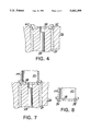
FIG. 6 is a bottom plan of the tool shown in FIG. 5 with a part broken away,
FIG. 7 is a fragmentary sectional view of the apparatus shown in FIG. 4 illustrating the use of our tool in our method of removing a stuck sprue.
FIG. 8 is a fragmentary sectional view of our tool carrying the sprue following its removal from the molding apparatus.
Referring now to FIG, 1, a molding apparatus indicated generally by the reference character 10 for use in forming a compact disc or the like includes an upper movable mold half 12 and a lower stationary mold half 14. A plastic injector 16 has an outlet passage 18 for injecting plastic into the mold cavity through an injector bushing 20.
The stationary lower mold half 14 includes a sprue ejector 22 carrying a gate cutter 24 received in a bushing 26 in the stationary lower mold member 14, The ejector 22 has a central bore which slideably receives a knockout pin 28 in a manner known to the art.
In operation of the apparatus 10, the upper and lower mold members 12 and 14 are brought together to form the die cavity 30. Plastic introduced into the cavity 30 through the injector outlet 18 also flows into an internal annular recess 32 in the upper end of the gate cutter 24.
It will be seen that following the operation of injecting plastic into the mold assembly, the compact disc forming material 34 is in the cavity 30 and a sprue includes an elongated center portion 36 extending upwardly into the passage 18 and slightly downwardly into the bore which receives the knockout pin 28, as well as a surrounding sprue part 38 including a boss 40 disposed in the recess 32.
In normal operation of the apparatus, after the filling operation, the apparatus is cooled and then the upper section 12 moves away. The ejector 22 and the gate cutter 24 move downwardly relative to the bushing 26, as illustrated in FIG. 2. In the course of this operation the central portion of the disc is pulled downwardly and cut by the sharp inner edge of the bushing 26. This action is illustrated in FIG. 2.
Following the cutting operation shown in FIG. 2, the ejector 22 and the pin 28 move further downwardly until the pin 28 strikes an abutment. As the ejector 22 continues to move downwardly, the pin 28 knocks the sprue out of the bushing 26, as illustrated in FIG. 3.
Owing to the rapidity with which the operations take place and the rapid cooling of the plastic material, it sometimes occurs that in the course of the knockout operation illustrated in FIG. 3, instead of knocking the entire sprue out of the bushing 26, the knockout pin 28 punches a hole in the middle of the central portion 38 of the sprue to leave the condition illustrated in FIG. 4. Upon further cooling of the plastic material, it adheres firmly to the gate cutter 24 and in accordance with the prior art must be melted out of the assembly by use of a torch.
Referring now to FIGS. 6 to 8, our tool, indicated generally by the reference character 42, for use in our method of removing a stuck sprue, includes a body 44 provided with a threaded central bore 46 which may, for example, receive the threaded portion 48 of the shank 50 of a T-handle 52. We form the lower end of the body 44 with a cylindrical recess 54. The lower edge of the tool 42 is formed with a plurality of notches or the like which, in the embodiment illustrated in the drawings, are semi-circular indentations 56, 58, 60 and 62 in the lower end of the tool. It will readily be appreciated that the tool body 44 is formed of some heat conductive material, such for example as steel or the like.
In use of the tool 42 to remove a stuck sprue, the lower end of the tool is first heated by means of a blowtorch or the like to a temperature which is above the melting point of the plastic material. It may, for example, be heated to a red hot condition. After heating, the lower end of the tool is pressed into the sprue at a location adjacent to the boss 40, as illustrated in FIG. 7. At this point, it will be seen that the melted plastic material flows into the indentations or recesses 56, 58, 60 and 62 in the lower end of the tool body 44. Once the lower end of the tool is seated properly, air is blown on the tool to cool it down. It will be appreciated that a source of compressed air to perform this operation is available at the site of the molding machine. Once the tool is cooled, handle 52 is rotated left to right to ensure that the tool is attached to the sprue. When that operation is complete, the tool is rocked back and forth to rock the sprue free of the gate cutter 24 and ejector 22. At this point, the sprue is free of the molding apparatus and attached to the tool as illustrated in FIG. 8.
It will be seen that we have accomplished the objects of our invention. We have provided an improved method of removing a stuck sprue from an injection molding apparatus and a tool for use in practicing the method. Our method and tool facilitate the removal of a stuck sprue in a rapid and expeditious manner. Our tool is simple in construction and inexpensive to manufacture.
It will be understood that certain features and subcombinations are of utility and may be employed without reference to other features and subcombinations. This is contemplated by and is within the scope of our claims without departing from the spirit of our invention. It is, therefore, to be understood that our invention is not to be limited to the specific details shown and described.
Claims (5)
1. A tool for use in removing a stuck sprue from the sprue ejector mechanism of an injection molding machine including a body of thermally conductive material, said body having a hollow lower portion with an open lower end, the edge of said lower end of said hollow lower portion having at least one axially extending indentation therein and a handle attached to said body.
2. A tool as in claim 1 in which said body is metal.
3. A tool as in claim 1 in which said edge of said lower end of said hollow lower portion is formed with a pluraltiy of peripherally spaced axially extending indentations therein.
4. A tool as in claim 1 in which said body is cylindrical.
5. A tool as in claim 4 in which said indentations are arcuate.
Priority Applications (1)
| Application Number | Priority Date | Filing Date | Title |
|---|---|---|---|
| US08/297,260 US5441399A (en) | 1993-12-21 | 1994-08-26 | Method of removing stuck sprue and tool for removal therein |
Applications Claiming Priority (2)
| Application Number | Priority Date | Filing Date | Title |
|---|---|---|---|
| US08/171,097 US5391332A (en) | 1993-12-21 | 1993-12-21 | Method of removing stuck sprue |
| US08/297,260 US5441399A (en) | 1993-12-21 | 1994-08-26 | Method of removing stuck sprue and tool for removal therein |
Related Parent Applications (1)
| Application Number | Title | Priority Date | Filing Date |
|---|---|---|---|
| US08/171,097 Division US5391332A (en) | 1993-12-21 | 1993-12-21 | Method of removing stuck sprue |
Publications (1)
| Publication Number | Publication Date |
|---|---|
| US5441399A true US5441399A (en) | 1995-08-15 |
Family
ID=22622516
Family Applications (2)
| Application Number | Title | Priority Date | Filing Date |
|---|---|---|---|
| US08/171,097 Expired - Lifetime US5391332A (en) | 1993-12-21 | 1993-12-21 | Method of removing stuck sprue |
| US08/297,260 Expired - Fee Related US5441399A (en) | 1993-12-21 | 1994-08-26 | Method of removing stuck sprue and tool for removal therein |
Family Applications Before (1)
| Application Number | Title | Priority Date | Filing Date |
|---|---|---|---|
| US08/171,097 Expired - Lifetime US5391332A (en) | 1993-12-21 | 1993-12-21 | Method of removing stuck sprue |
Country Status (1)
| Country | Link |
|---|---|
| US (2) | US5391332A (en) |
Cited By (6)
| Publication number | Priority date | Publication date | Assignee | Title |
|---|---|---|---|---|
| US5720994A (en) * | 1995-10-09 | 1998-02-24 | Meiki Co., Ltd. | Mold for molding discs to be laminated into double discs |
| EP1066947A2 (en) * | 1999-06-30 | 2001-01-10 | HEKUMA Herbst Maschinenbau GmbH | Tempering method as well as plastic injection moulding machine with a handling system |
| US20040178538A1 (en) * | 2003-03-14 | 2004-09-16 | Guide Corporation | In-mold degating system |
| US20080175947A1 (en) * | 2007-01-19 | 2008-07-24 | Shenzhen Futaihong Precision Industry Co., Ltd. | Cut structure for mold |
| US20080259384A1 (en) * | 2006-12-18 | 2008-10-23 | Canon Kabushiki Kaisha | Image forming system and information processing apparatus |
| US20090317508A1 (en) * | 2008-06-24 | 2009-12-24 | Hon Hai Precision Industry Co., Ltd. | Mold clearing tool |
Families Citing this family (3)
| Publication number | Priority date | Publication date | Assignee | Title |
|---|---|---|---|---|
| US7175788B2 (en) * | 2004-09-24 | 2007-02-13 | Graham Packaging Company, L.P. | Device and method for removal of preforms |
| CN101112783B (en) * | 2006-07-28 | 2011-09-21 | 深圳富泰宏精密工业有限公司 | Method for making plastic cement products |
| CN108274691A (en) * | 2018-03-28 | 2018-07-13 | 天津中德应用技术大学 | Injection mold condensate remove device |
Citations (15)
| Publication number | Priority date | Publication date | Assignee | Title |
|---|---|---|---|---|
| US2471148A (en) * | 1948-01-06 | 1949-05-24 | Gen Electric | Sprue cutter for transfer molding devices |
| US2923031A (en) * | 1958-03-04 | 1960-02-02 | Nothelfer & Sohne A | Device for removing the sprue from objects produced by injection molding operations |
| DE1112281B (en) * | 1957-05-17 | 1961-08-03 | Nothelfer & Soehne Werkzeug Un | Process for removing the sprue in products from plastic injection molding machines and device for carrying out the process |
| US3013303A (en) * | 1960-03-15 | 1961-12-19 | Irving J Amazon | Degating device for plastic moulds |
| US3208113A (en) * | 1962-12-14 | 1965-09-28 | Koehring Co | Die casting machine |
| US3443001A (en) * | 1966-02-17 | 1969-05-06 | Western Electric Co | Method and mechanism for severing the gate in injection-type molds |
| US3811175A (en) * | 1969-12-15 | 1974-05-21 | Ici Ltd | Method of making a split mold |
| JPS58134724A (en) * | 1982-02-06 | 1983-08-11 | Sony Corp | Resin molding device |
| JPS58177326A (en) * | 1982-04-12 | 1983-10-18 | Matsushita Electric Ind Co Ltd | Apparatus for molding disklike recording medium |
| US4442619A (en) * | 1981-12-21 | 1984-04-17 | Mccarley Roy J | Cartridge extraction tool |
| US4466934A (en) * | 1980-10-31 | 1984-08-21 | Discovision Associates | Hot sprue valve assembly for an injection molding machine |
| US4585260A (en) * | 1982-05-21 | 1986-04-29 | Societe Invo Plastic S.A.R.L. | Device for gripping articles for robot-type manipulator |
| US4715806A (en) * | 1984-11-16 | 1987-12-29 | Krauss-Maffei A.G. | Apparatus for the punching and removing of the sprue in an injection molding tool |
| US4787841A (en) * | 1986-12-02 | 1988-11-29 | Hans Simon | Sprue ejector in automatic injection molding machines |
| US4824358A (en) * | 1987-07-17 | 1989-04-25 | Shinkoh Sellbic Co., Ltd. | Resin molding die |
-
1993
- 1993-12-21 US US08/171,097 patent/US5391332A/en not_active Expired - Lifetime
-
1994
- 1994-08-26 US US08/297,260 patent/US5441399A/en not_active Expired - Fee Related
Patent Citations (15)
| Publication number | Priority date | Publication date | Assignee | Title |
|---|---|---|---|---|
| US2471148A (en) * | 1948-01-06 | 1949-05-24 | Gen Electric | Sprue cutter for transfer molding devices |
| DE1112281B (en) * | 1957-05-17 | 1961-08-03 | Nothelfer & Soehne Werkzeug Un | Process for removing the sprue in products from plastic injection molding machines and device for carrying out the process |
| US2923031A (en) * | 1958-03-04 | 1960-02-02 | Nothelfer & Sohne A | Device for removing the sprue from objects produced by injection molding operations |
| US3013303A (en) * | 1960-03-15 | 1961-12-19 | Irving J Amazon | Degating device for plastic moulds |
| US3208113A (en) * | 1962-12-14 | 1965-09-28 | Koehring Co | Die casting machine |
| US3443001A (en) * | 1966-02-17 | 1969-05-06 | Western Electric Co | Method and mechanism for severing the gate in injection-type molds |
| US3811175A (en) * | 1969-12-15 | 1974-05-21 | Ici Ltd | Method of making a split mold |
| US4466934A (en) * | 1980-10-31 | 1984-08-21 | Discovision Associates | Hot sprue valve assembly for an injection molding machine |
| US4442619A (en) * | 1981-12-21 | 1984-04-17 | Mccarley Roy J | Cartridge extraction tool |
| JPS58134724A (en) * | 1982-02-06 | 1983-08-11 | Sony Corp | Resin molding device |
| JPS58177326A (en) * | 1982-04-12 | 1983-10-18 | Matsushita Electric Ind Co Ltd | Apparatus for molding disklike recording medium |
| US4585260A (en) * | 1982-05-21 | 1986-04-29 | Societe Invo Plastic S.A.R.L. | Device for gripping articles for robot-type manipulator |
| US4715806A (en) * | 1984-11-16 | 1987-12-29 | Krauss-Maffei A.G. | Apparatus for the punching and removing of the sprue in an injection molding tool |
| US4787841A (en) * | 1986-12-02 | 1988-11-29 | Hans Simon | Sprue ejector in automatic injection molding machines |
| US4824358A (en) * | 1987-07-17 | 1989-04-25 | Shinkoh Sellbic Co., Ltd. | Resin molding die |
Cited By (8)
| Publication number | Priority date | Publication date | Assignee | Title |
|---|---|---|---|---|
| US5720994A (en) * | 1995-10-09 | 1998-02-24 | Meiki Co., Ltd. | Mold for molding discs to be laminated into double discs |
| EP1066947A2 (en) * | 1999-06-30 | 2001-01-10 | HEKUMA Herbst Maschinenbau GmbH | Tempering method as well as plastic injection moulding machine with a handling system |
| EP1066947A3 (en) * | 1999-06-30 | 2002-12-18 | HEKUMA Herbst Maschinenbau GmbH | Tempering method as well as plastic injection moulding machine with a handling system |
| US20040178538A1 (en) * | 2003-03-14 | 2004-09-16 | Guide Corporation | In-mold degating system |
| US20080259384A1 (en) * | 2006-12-18 | 2008-10-23 | Canon Kabushiki Kaisha | Image forming system and information processing apparatus |
| US20080175947A1 (en) * | 2007-01-19 | 2008-07-24 | Shenzhen Futaihong Precision Industry Co., Ltd. | Cut structure for mold |
| US20090317508A1 (en) * | 2008-06-24 | 2009-12-24 | Hon Hai Precision Industry Co., Ltd. | Mold clearing tool |
| US7988443B2 (en) * | 2008-06-24 | 2011-08-02 | Hon Hai Precision Industry Co., Ltd. | Mold clearing tool |
Also Published As
| Publication number | Publication date |
|---|---|
| US5391332A (en) | 1995-02-21 |
Similar Documents
| Publication | Publication Date | Title |
|---|---|---|
| US2330369A (en) | Apparatus for molding plastic material | |
| US5441399A (en) | Method of removing stuck sprue and tool for removal therein | |
| KR860001332B1 (en) | Hot sprue valve and mold assembly for an injection molding machine and a method for controlling flow of molten material | |
| KR910001178B1 (en) | Vertical injection apparatus | |
| US2777164A (en) | Injection moulding machine | |
| NO303051B1 (en) | Method and apparatus for blasting plastic objects during gas assist | |
| US4779665A (en) | Die casting apparatus and process comprising in-die plunger densification to form a bore through a product casting | |
| US4662205A (en) | Machine for cold die casting malleable metals | |
| EP0462969A1 (en) | Method and system for making a hollow-shaped body from molten resin by injection molding. | |
| US4439132A (en) | Hot sprue assembly for an injection molding machine | |
| US2968821A (en) | Apparatus and method for forming locknuts having a washer molded in the nut body | |
| US5340303A (en) | Faster cycling sprue for centerhole - tearout optical disk injection molds | |
| US6604933B1 (en) | Universal nozzle tip for injection molding | |
| US5997788A (en) | Method of releasing thin discs in molding | |
| US2375486A (en) | Method of trimming gates of die castings | |
| JPS63281817A (en) | Injection mold assembly | |
| US2896258A (en) | Apparatus for injection molding of plastic articles | |
| KR0136498Y1 (en) | Mold gate cutting apparatus | |
| JP3859037B2 (en) | Injection mold for hollow products | |
| JPH0376808B2 (en) | ||
| JP3278104B2 (en) | Method for producing resin molded article having hollow portion | |
| JPH0337922B2 (en) | ||
| JPH081061Y2 (en) | Thread pull prevention block and nozzle device of injection molding machine having the same | |
| US3550210A (en) | Apparatus for molding articles | |
| JPH0655586A (en) | Injection molding die |
Legal Events
| Date | Code | Title | Description |
|---|---|---|---|
| FPAY | Fee payment |
Year of fee payment: 4 |
|
| FEPP | Fee payment procedure |
Free format text: PAYOR NUMBER ASSIGNED (ORIGINAL EVENT CODE: ASPN); ENTITY STATUS OF PATENT OWNER: LARGE ENTITY |
|
| REMI | Maintenance fee reminder mailed | ||
| LAPS | Lapse for failure to pay maintenance fees | ||
| FP | Lapsed due to failure to pay maintenance fee |
Effective date: 20030815 |
|
| STCH | Information on status: patent discontinuation |
Free format text: PATENT EXPIRED DUE TO NONPAYMENT OF MAINTENANCE FEES UNDER 37 CFR 1.362 |