US5437450A - Golf club shaft and process of preparing same - Google Patents

Golf club shaft and process of preparing same Download PDF

Info

Publication number
US5437450A
US5437450A US08/297,028 US29702894A US5437450A US 5437450 A US5437450 A US 5437450A US 29702894 A US29702894 A US 29702894A US 5437450 A US5437450 A US 5437450A
Authority
US
United States
Prior art keywords
layer
mandrel
kgf
shaft
inner layer
Prior art date
Legal status (The legal status is an assumption and is not a legal conclusion. Google has not performed a legal analysis and makes no representation as to the accuracy of the status listed.)
Expired - Fee Related
Application number
US08/297,028
Inventor
Tsuneo Akatsuka
Yoshihiro Motoki
Takashi Harada
Akira Suzawa
Current Assignee (The listed assignees may be inaccurate. Google has not performed a legal analysis and makes no representation or warranty as to the accuracy of the list.)
Somar Corp
Original Assignee
Somar Corp
Priority date (The priority date is an assumption and is not a legal conclusion. Google has not performed a legal analysis and makes no representation as to the accuracy of the date listed.)
Filing date
Publication date
Application filed by Somar Corp filed Critical Somar Corp
Assigned to SOMAR CORPORATION reassignment SOMAR CORPORATION ASSIGNMENT OF ASSIGNORS INTEREST (SEE DOCUMENT FOR DETAILS). Assignors: AKATSUKA, TSUNEO, HARADA, TAKASHI, MOTOKI, YOSHIHIRO, SUZAWA, AKIRA
Application granted granted Critical
Publication of US5437450A publication Critical patent/US5437450A/en
Anticipated expiration legal-status Critical
Expired - Fee Related legal-status Critical Current

Links

Images

Classifications

    • BPERFORMING OPERATIONS; TRANSPORTING
    • B29WORKING OF PLASTICS; WORKING OF SUBSTANCES IN A PLASTIC STATE IN GENERAL
    • B29CSHAPING OR JOINING OF PLASTICS; SHAPING OF MATERIAL IN A PLASTIC STATE, NOT OTHERWISE PROVIDED FOR; AFTER-TREATMENT OF THE SHAPED PRODUCTS, e.g. REPAIRING
    • B29C70/00Shaping composites, i.e. plastics material comprising reinforcements, fillers or preformed parts, e.g. inserts
    • B29C70/04Shaping composites, i.e. plastics material comprising reinforcements, fillers or preformed parts, e.g. inserts comprising reinforcements only, e.g. self-reinforcing plastics
    • B29C70/06Fibrous reinforcements only
    • B29C70/10Fibrous reinforcements only characterised by the structure of fibrous reinforcements, e.g. hollow fibres
    • B29C70/16Fibrous reinforcements only characterised by the structure of fibrous reinforcements, e.g. hollow fibres using fibres of substantial or continuous length
    • B29C70/22Fibrous reinforcements only characterised by the structure of fibrous reinforcements, e.g. hollow fibres using fibres of substantial or continuous length oriented in at least two directions forming a two dimensional structure
    • B29C70/228Fibrous reinforcements only characterised by the structure of fibrous reinforcements, e.g. hollow fibres using fibres of substantial or continuous length oriented in at least two directions forming a two dimensional structure the structure being stacked in parallel layers with fibres of adjacent layers crossing at substantial angles
    • AHUMAN NECESSITIES
    • A63SPORTS; GAMES; AMUSEMENTS
    • A63BAPPARATUS FOR PHYSICAL TRAINING, GYMNASTICS, SWIMMING, CLIMBING, OR FENCING; BALL GAMES; TRAINING EQUIPMENT
    • A63B53/00Golf clubs
    • A63B53/10Non-metallic shafts
    • AHUMAN NECESSITIES
    • A63SPORTS; GAMES; AMUSEMENTS
    • A63BAPPARATUS FOR PHYSICAL TRAINING, GYMNASTICS, SWIMMING, CLIMBING, OR FENCING; BALL GAMES; TRAINING EQUIPMENT
    • A63B60/00Details or accessories of golf clubs, bats, rackets or the like
    • BPERFORMING OPERATIONS; TRANSPORTING
    • B29WORKING OF PLASTICS; WORKING OF SUBSTANCES IN A PLASTIC STATE IN GENERAL
    • B29CSHAPING OR JOINING OF PLASTICS; SHAPING OF MATERIAL IN A PLASTIC STATE, NOT OTHERWISE PROVIDED FOR; AFTER-TREATMENT OF THE SHAPED PRODUCTS, e.g. REPAIRING
    • B29C70/00Shaping composites, i.e. plastics material comprising reinforcements, fillers or preformed parts, e.g. inserts
    • B29C70/04Shaping composites, i.e. plastics material comprising reinforcements, fillers or preformed parts, e.g. inserts comprising reinforcements only, e.g. self-reinforcing plastics
    • B29C70/06Fibrous reinforcements only
    • B29C70/08Fibrous reinforcements only comprising combinations of different forms of fibrous reinforcements incorporated in matrix material, forming one or more layers, and with or without non-reinforced layers
    • B29C70/083Combinations of continuous fibres or fibrous profiled structures oriented in one direction and reinforcements forming a two dimensional structure, e.g. mats
    • B29C70/085Combinations of continuous fibres or fibrous profiled structures oriented in one direction and reinforcements forming a two dimensional structure, e.g. mats the structure being deformed in a three dimensional configuration
    • BPERFORMING OPERATIONS; TRANSPORTING
    • B29WORKING OF PLASTICS; WORKING OF SUBSTANCES IN A PLASTIC STATE IN GENERAL
    • B29CSHAPING OR JOINING OF PLASTICS; SHAPING OF MATERIAL IN A PLASTIC STATE, NOT OTHERWISE PROVIDED FOR; AFTER-TREATMENT OF THE SHAPED PRODUCTS, e.g. REPAIRING
    • B29C70/00Shaping composites, i.e. plastics material comprising reinforcements, fillers or preformed parts, e.g. inserts
    • B29C70/04Shaping composites, i.e. plastics material comprising reinforcements, fillers or preformed parts, e.g. inserts comprising reinforcements only, e.g. self-reinforcing plastics
    • B29C70/28Shaping operations therefor
    • B29C70/30Shaping by lay-up, i.e. applying fibres, tape or broadsheet on a mould, former or core; Shaping by spray-up, i.e. spraying of fibres on a mould, former or core
    • AHUMAN NECESSITIES
    • A63SPORTS; GAMES; AMUSEMENTS
    • A63BAPPARATUS FOR PHYSICAL TRAINING, GYMNASTICS, SWIMMING, CLIMBING, OR FENCING; BALL GAMES; TRAINING EQUIPMENT
    • A63B2209/00Characteristics of used materials
    • A63B2209/02Characteristics of used materials with reinforcing fibres, e.g. carbon, polyamide fibres
    • AHUMAN NECESSITIES
    • A63SPORTS; GAMES; AMUSEMENTS
    • A63BAPPARATUS FOR PHYSICAL TRAINING, GYMNASTICS, SWIMMING, CLIMBING, OR FENCING; BALL GAMES; TRAINING EQUIPMENT
    • A63B60/00Details or accessories of golf clubs, bats, rackets or the like
    • A63B60/06Handles
    • AHUMAN NECESSITIES
    • A63SPORTS; GAMES; AMUSEMENTS
    • A63BAPPARATUS FOR PHYSICAL TRAINING, GYMNASTICS, SWIMMING, CLIMBING, OR FENCING; BALL GAMES; TRAINING EQUIPMENT
    • A63B60/00Details or accessories of golf clubs, bats, rackets or the like
    • A63B60/06Handles
    • A63B60/08Handles characterised by the material
    • AHUMAN NECESSITIES
    • A63SPORTS; GAMES; AMUSEMENTS
    • A63BAPPARATUS FOR PHYSICAL TRAINING, GYMNASTICS, SWIMMING, CLIMBING, OR FENCING; BALL GAMES; TRAINING EQUIPMENT
    • A63B60/00Details or accessories of golf clubs, bats, rackets or the like
    • A63B60/06Handles
    • A63B60/10Handles with means for indicating correct holding positions
    • BPERFORMING OPERATIONS; TRANSPORTING
    • B29WORKING OF PLASTICS; WORKING OF SUBSTANCES IN A PLASTIC STATE IN GENERAL
    • B29CSHAPING OR JOINING OF PLASTICS; SHAPING OF MATERIAL IN A PLASTIC STATE, NOT OTHERWISE PROVIDED FOR; AFTER-TREATMENT OF THE SHAPED PRODUCTS, e.g. REPAIRING
    • B29C53/00Shaping by bending, folding, twisting, straightening or flattening; Apparatus therefor
    • B29C53/56Winding and joining, e.g. winding spirally
    • BPERFORMING OPERATIONS; TRANSPORTING
    • B29WORKING OF PLASTICS; WORKING OF SUBSTANCES IN A PLASTIC STATE IN GENERAL
    • B29LINDEXING SCHEME ASSOCIATED WITH SUBCLASS B29C, RELATING TO PARTICULAR ARTICLES
    • B29L2031/00Other particular articles
    • B29L2031/52Sports equipment ; Games; Articles for amusement; Toys
    • B29L2031/5227Clubs
    • YGENERAL TAGGING OF NEW TECHNOLOGICAL DEVELOPMENTS; GENERAL TAGGING OF CROSS-SECTIONAL TECHNOLOGIES SPANNING OVER SEVERAL SECTIONS OF THE IPC; TECHNICAL SUBJECTS COVERED BY FORMER USPC CROSS-REFERENCE ART COLLECTIONS [XRACs] AND DIGESTS
    • Y10TECHNICAL SUBJECTS COVERED BY FORMER USPC
    • Y10STECHNICAL SUBJECTS COVERED BY FORMER USPC CROSS-REFERENCE ART COLLECTIONS [XRACs] AND DIGESTS
    • Y10S273/00Amusement devices: games
    • Y10S273/23High modulus filaments
    • YGENERAL TAGGING OF NEW TECHNOLOGICAL DEVELOPMENTS; GENERAL TAGGING OF CROSS-SECTIONAL TECHNOLOGIES SPANNING OVER SEVERAL SECTIONS OF THE IPC; TECHNICAL SUBJECTS COVERED BY FORMER USPC CROSS-REFERENCE ART COLLECTIONS [XRACs] AND DIGESTS
    • Y10TECHNICAL SUBJECTS COVERED BY FORMER USPC
    • Y10TTECHNICAL SUBJECTS COVERED BY FORMER US CLASSIFICATION
    • Y10T428/00Stock material or miscellaneous articles
    • Y10T428/13Hollow or container type article [e.g., tube, vase, etc.]
    • Y10T428/1352Polymer or resin containing [i.e., natural or synthetic]
    • Y10T428/1369Fiber or fibers wound around each other or into a self-sustaining shape [e.g., yarn, braid, fibers shaped around a core, etc.]
    • YGENERAL TAGGING OF NEW TECHNOLOGICAL DEVELOPMENTS; GENERAL TAGGING OF CROSS-SECTIONAL TECHNOLOGIES SPANNING OVER SEVERAL SECTIONS OF THE IPC; TECHNICAL SUBJECTS COVERED BY FORMER USPC CROSS-REFERENCE ART COLLECTIONS [XRACs] AND DIGESTS
    • Y10TECHNICAL SUBJECTS COVERED BY FORMER USPC
    • Y10TTECHNICAL SUBJECTS COVERED BY FORMER US CLASSIFICATION
    • Y10T428/00Stock material or miscellaneous articles
    • Y10T428/13Hollow or container type article [e.g., tube, vase, etc.]
    • Y10T428/1352Polymer or resin containing [i.e., natural or synthetic]
    • Y10T428/139Open-ended, self-supporting conduit, cylinder, or tube-type article

Definitions

  • This invention relates to a golf club shaft formed of a carbon fiber-reinforced plastic and to a process for the fabrication thereof.
  • CFRP shafts are now increasingly used because they are lighter in weight and provide golf clubs which can hit a golf ball longer distance as compared with conventional steel club shafts.
  • CFRP shafts are produced by a sheet winding method in which a prepreg sheet containing carbon fibers dispersed in a matrix of a hardenable resin is wound around a mandrel or by a filament winding method in which a tow or roving of carbon fibers impregnated with a hardenable resin is wound around a mandrel.
  • a CFRP shaft produced by the sheet winding method shows satisfactory mechanical strengths but encounters a problem because the flexural rigidity varies at different positions around the circumference.
  • the resulting golf club assembly gives a player a swing feeling that varies with the relative position therebetween. This follows that it is necessary to assemble the head and the shaft with a specific relative position.
  • JP-A-57-142271 discloses a process for the production of a CFRP shaft having an improved strength and torsional rigidity, which includes the steps of winding a prepreg sheet containing carbon fibers dispersed in a matrix of a hardenable resin around a mandrel to form an inner layer, then winding a roving of carbon fibers impregnated with a hardenable resin around the inner layer to form an outer layer, and then hardening the inner and outer layers together.
  • JP-A-2-111380 discloses a process for the preparation of a golf club shaft having a tip end and a grip end, which includes the steps of winding a prepreg sheet containing carbon fibers dispersed in a matrix of a hardenable resin around a mandrel to form an inner layer extending from the grip end and terminating at least 100 mm away from the tip end, then winding a roving of carbon fibers impregnated with a hardenable resin around the inner layer to form an intermediate layer extending from the grip end to the tip end, then winding a roving of glass fibers impregnated with a hardenable resin around the intermediate layer throughout the length thereof to form an outer layer, and then hardening the inner, intermediate and outer layer together.
  • Another object of the present invention is to provide a golf club shaft of the above-mentioned type which shows uniform deflection characteristics around the circumference and which can be produced economically with good producibility.
  • the present invention provides a golf club shaft having a grip end, a tip end, an outer diameter gradually decreasing from the grip end to the tip end, and an average weight of not greater than 1.4 g per inch.
  • the shaft includes:
  • an outer tubular layer provided contiguously around the inner layer throughout the length thereof and formed of a hardened, second carbon fiber-reinforced plastic material, the outer layer containing a second carbon fiber group having a modulus of 24,000 kgf/mm 2 or more and a tensile strength of 450 kgf/mm 2 or more and oriented at an angle in the range of 5 to 30 degrees with respect to the longitudinal axis of the shaft, and
  • a tubular, reinforcing layer provided inside of the inner layer and extending from the tip end with a length of 50 to 500 mm, the reinforcing layer being formed of a hardened, reinforcing fiber-reinforced plastic containing a fiber group having a modulus of 20,000 kgf/mm 2 or more and a tensile strength of 500 kgf/mm 2 or more and oriented at an angle in the range of 0 to 5 degrees with respect to the longitudinal axis of the shaft,
  • the weight ratio of the inner layer to the outer layer being in the range of 20:80 to 55:45
  • the thickness ratio of the inner layer to the outer layer being in the range of 1:3 to 1:1
  • the inner layer being obtained from a prepreg sheet containing the first carbon fiber group uniaxially oriented within a matrix of a first hardenable resin
  • the reinforcing layer being obtained from a prepreg sheet containing the reinforcing fiber group uniaxially oriented within a matrix of a second hardenable resin,
  • the outer layer being obtained from windings of a roving of the second carbon fiber groups impregnated with a third hardenable resin
  • the first and second hardenable resins having been hardened before the winding of the roving.
  • the present invention provides a process for the preparation of a golf club shaft, which includes the steps of:
  • FIGURE is an elevational view, cut away in part, showing the construction and fiber orientation of the layers, in the tip end and grip end portions, of a golf club shaft according to the present invention.
  • a golf club shaft according to one embodiment of the present invention.
  • the shaft 11 in this embodiment is illustrated as being wound on a mandrel 10 having an outer diameter gradually increasing from one end adjacent to a tip end of the shaft 10 to the other end adjacent to a grip end of the shaft 10.
  • the shaft 11 has an inner tubular layer 1 formed of a hardened, first carbon fiber-reinforced plastic and extending continuously between the tip end and the grip end thereof.
  • the inner layer 1 contains a first carbon fiber group oriented at an angle ⁇ in the range of 40 to 50 degrees with respect to the longitudinal axis of the shaft 11.
  • the inner layer 1 is formed of two kinds of wound layers each of which has the same filament orientation angle but which have filament orientation directions opposite to each other with respect to the longitudinal axis of the shaft as shown in the FIGURE.
  • the orientation angle of the fibers e.g. ⁇ of the first carbon fibers of the inner layer
  • ⁇ of 45° indicates either of the positive and negative positions ( ⁇ 45°) relative to the axis of the shaft.
  • the first carbon fiber from which the inner layer 1 is formed is a high modulus carbon fiber having a modulus of 29,000 kgf/mm 2 or more, preferably 40,000 kgf/mm 2 or more and a tensile strength of 300 kgf/mm 2 or more, preferably 350 kgf/mm 2 or more.
  • the elongation of the first carbon fiber is generally 0.5-1.8%, preferably 0.5-1.0%.
  • suitable high modulus carbon fibers are those commercially available under the trade names of T800, M30S, M40J, M46J, M50J, M55J, M60J and M65J (products by Toray Kabushiki Kaisha) and HMS-40, HMS-46, HMS-55 and HMS-63 (products of Tohoh Rayon Kabushiki Kaisha) and IM-400, IM-600, UM-40, UM-46, UM-55, UM-63 and UM-68 (products of Tohoh Rayon Kabushiki Kaisha).
  • the inner layer 1 generally has a carbon fiber content of 65-80% by weight, preferably 70-76% by weight. In terms of volumetric percentage, the carbon fiber content is generally 55-75% by volume, preferably 60-70% by volume.
  • the plastic material used as a binder or matrix resin for the first carbon fiber is generally a thermosetting resin such as an epoxy resin or an unsaturated polyester resin. An epoxy resin is preferably used.
  • the inner layer 1 is formed by a sheet winding method using a prepreg containing the first carbon fibers uniaxially oriented within a matrix of a hardenable resin composition.
  • an outer tubular layer 2 extending throughout the length the shaft 11 and formed of a hardened, second carbon fiber-reinforced plastic.
  • the outer layer 2 contains a second carbon fiber group oriented at an angle in the range of 5 to 30 degrees with respect to the longitudinal axis of the shaft 11.
  • the outer layer 2 is formed of a plurality of wound layers arranged such that the orientation angle the carbon fiber groups of respective layers relative to the longitudinal axis of the shaft is the same but the orientation directions of the fiber groups of each adjacent two layers are opposite to each other with respect to the longitudinal axis of the shaft as shown in the FIGURE.
  • the second carbon fiber from which the outer layer 2 is formed is a high modulus and high strength carbon fiber having a modulus of 24,000 kgf/mm 2 or more, preferably 30,000 kgf/mm 2 or more, and a tensile strength of 450 kgf/mm 2 or more, preferably 550 kgf/mm 2 or more.
  • the elongation of the second carbon fiber is generally 0.8-2.1%, preferably 1.0-2.1%.
  • suitable high modulus carbon fibers are those commercially available under the trade names of T700S, T800, M30S, M35J, M40J and M46J (products by Toray Kabushiki Kaisha) and HMS-40, HMS-46, HMS-55 and HMS-63 (products of Tohoh Rayon Kabushiki Kaisha) and UT-500, IM-400, IM-600, UM-40 and UM-46 (products of Tohoh Rayon Kabushiki Kaisha).
  • the outer layer 2 generally has a carbon fiber content of 65-80% by weight, preferably 67-75% by weight. In terms of volumetric percentage, the carbon fiber content is generally 55-70% by volume, preferably 58-67% by volume.
  • the plastic material used as a binder or matrix resin for the second carbon fiber is generally a thermosetting resin such as an epoxy resin or an unsaturated polyester resin. An epoxy resin is preferably used.
  • the outer layer 2 is formed by a filament winding method using a tow or roving of the second carbon fibers impregnated with a hardenable resin composition.
  • Designated as 3 is a tubular reinforcing layer provided inside of the inner layer 1 and extending from the tip end of the shaft through a length L 1 of 50 to 500 mm, preferably 100-300 mm.
  • the reinforcing layer 3 is formed of a fiber-reinforced plastic containing reinforcing fiber group oriented at an angle in the range of 0 to 5 degrees with respect to the longitudinal axis of the shaft 11.
  • the reinforcing layer 3 serves to improve the bending modulus and impact resistance of the shaft 11.
  • the fiber from which the reinforcing layer 3 is formed is a high strength fiber such as a carbon fiber, a boron fiber, titanium fiber, an aromatic polyamide fiber or a polyethylene fiber. These fibers may be used by themselves or as a mixture or in combination of two or more. A carbon fiber is preferably used.
  • the reinforcing fiber has a modulus of 20,000 kgf/mm 2 or more, preferably 23,000 kgf/mm 2 or more, and a tensile strength of 400 kgf/mm 2 or more, preferably 500 kgf/mm 2 or more.
  • the elongation of the reinforcing fiber is generally 1.5-2.1%, preferably 1.8-2.1%.
  • the reinforcing layer 3 generally has a fiber content of 65-76% by weight, preferably 67-70% by weight. In terms of volumetric percentage, the carbon fiber content is generally 55-70% by volume, preferably 58-62% by volume.
  • the plastic material used as a binder or matrix resin for the reinforcing fiber is generally a thermosetting resin such as an epoxy resin or an unsaturated polyester resin. An epoxy resin is preferably used.
  • the reinforcing layer 3 is formed by a sheet winding method using a prepreg containing the reinforcing fibers uniaxially oriented within a matrix of a hardenable resin composition.
  • the weight ratio of the inner layer 1 to the outer layer 3 should be in the range of 20:80 to 55:45, preferably 30:70 to 45:55.
  • the thickness ratio of the inner layer 1 to the outer layer 3 should be in the range of 1:3 to 1:1, preferably 2:5 to 2:3.
  • a weight ratio in excess of 55:45 or a thickness ratio in excess of 1:1 is undesirable because the weight of the shaft increases and the uniformity of the bending modulus (flexural rigidity) of the shaft in the circumferential direction is lost.
  • the weight ratio is smaller than 20:80 or when the thickness ratio is smaller than 1:3, on the other hand, the torsional rigidity, bending modulus and buckling strength of the shaft are lowered.
  • the proportion of the reinforcing layer 3 in the shaft 11 is generally 5-25% by weight, preferably 10-25% by weight.
  • the total weight of the inner layer 1 and the outer layer 2 is generally 75-95% by weight, preferably 75-90% by weight, based on the weight of the shaft 11.
  • the total carbon fiber content of the shaft 11 is generally 65-75% by volume, preferably 65-70% by volume.
  • the length of the shaft of the present invention is generally 41-46 inches.
  • the tip end of the shaft has an inside diameter of 2-6 mm, preferably 3-4 mm and a wall thickness of 1.2-3.2 mm, preferably 1.7-2.7 mm, while the grip end has an inside diameter of 11.5-14.5 mm, preferably 12.5-13.5 mm and a wall thickness of 0.5-2.0 mm, preferably 0.7-1.5 mm.
  • the golf club shaft 11 according to the present invention may be produced by the following method.
  • a prepreg sheet (first prepreg) containing uniaxially oriented reinforcing fibers is cut from a stock material for the reinforcing layer 3 to the desired pattern and is wound around an axially elongated mandrel 10 having an outer diameter gradually increasing from one end thereof to the other end thereof.
  • the prepreg is cut so that the wound prepreg has an axial length of about 50-500 mm and the reinforcing fibers are oriented at an angle in the range of 0 to 5 degrees with respect to the axis of the mandrel 10.
  • the size is determined by the number of convolutions of the material that is to be wound around the mandrel 10.
  • the number of convolutions is determined by the weight and the thickness of the reinforcing layer 3 of the ultimate shaft 11.
  • a prepreg sheet is cut from a stock material for the inner layer 3 to the desired pattern and is wound the mandrel 10.
  • the prepreg is cut so that the wound prepreg has an axial length generally slightly greater than that of the ultimate shaft 11 and the first carbon fibers are oriented, when wound around the mandrel 10, at an angle in the range of 40 to 50 degrees with respect to the axis thereof.
  • the size is determined by the number of convolutions of the material that is to be wound around the mandrel 10.
  • the inner layer 1 be formed of two different kinds of wound layers.
  • two, first and second kinds of prepreg sheets having, for example, ⁇ 45° filament orientations are used.
  • the first and second prepregs may be alternately wound each through one complete convolution until the desired thickness is reached.
  • the first prepreg (+45°) may be wound through a desired number of convolutions, with the second prepreg (-45°) being subsequently wound through the same number of convolutions.
  • first and second wound layers (which are precursors of the reinforcing layer 3 and the inner layer 1, respectively) are then hardened so that the reinforcing layer 3 of the hardened first resin reinforced with the reinforcing fibers and the inner layer 1 of the hardened second resin reinforced with the first carbon fibers are formed around the mandrel 10.
  • the hardening is generally performed by heating at a temperature of 120°-150° C. for 2-4 hours. Prior to heating, it is preferred that the wound prepreg layers be held in position around the mandrel 10 by winding a tape, formed of, for example, a polypropylene, polyester or poly(vinyl fluoride) film, in the conventional manner.
  • a roving or tow of second carbon fibers impregnated with a hardenable resin is wound by a filament winding method around the hardened inner layer 1 supported by the mandrel 10 to form a third wound layer (a precursor of the outer layer 2) extending to entirely cover the inner layer 1 with the second carbon fibers being oriented at an angle in the range of 5 to 30 degrees with respect to the axis of the mandrel.
  • the roving is wound from one end to the other end with an orientation angle in the range of +5° to +30° and then from the other end to the one end at an orientation angle in the range of -5° to -30°.
  • Such reciprocal winding operation is continued until the wound layer has the desired thickness.
  • the third wound layer thus formed is then hardened in the same manner as the first and second wound layers to form an outer layer of the hardened third resin reinforced with the second carbon fibers.
  • the mandrel 10 is removed to leave a shaft composed of the reinforcing layer 3, the inner layer 1 and the outer layer 2.
  • the both ends of the shaft are cut to adjust the length thereof to a predetermined value and the outer surface of the shaft is ground to a predetermined diameter, thereby to obtain the ultimate shaft 11.
  • a prepreg sheet containing uniaxially aligned carbon fiber filaments impregnated with an epoxy resin composition was then wound on the smaller diameter end portion of the mandrel with the direction of the carbon fiber filament being oriented in substantially parallel with the longitudinal axis of the mandrel (namely, the carbon fibers are oriented at an angle of about 0 degree with respect to the axis of the mandrel) to form a wound reinforcing layer having a length of 250 mm (from the tip end of the shaft).
  • the prepreg sheet used was a commercially available one (P3052S-15 manufactured by Toray Kabushiki Kaisha) having a thickness of 0.15 mm, a carbon fiber weight of 150 g/m 2 , a resin content of 33% by weight (fiber content: 67% by weight) and a carbon fiber content of 58% by volume.
  • the carbon fiber of the prepreg sheet had a modulus of 23,500 kgf/mm 2 , a tensile strength of 490 kgf/mm 2 and an elongation of 2.1%.
  • the prepreg was wound around the mandrel so that the number of the convolutions was 1 (1 ply) at the larger diameter end (250 mm away from the tip end) and was 3.8 (3.8 plies) at the smaller diameter end.
  • prepreg sheets A-1 and A-2 Two kinds of prepreg sheets A-1 and A-2 were cut from a prepreg stock (P9055F-08 manufactured by Toray Kabushiki Kaisha) which contained uniaxially aligned carbon fiber filaments impregnated with an epoxy resin composition and which had a thickness of 0.06 mm, a carbon fiber weight of 75 g/m 2 , a resin content of 24% by weight (fiber content: 76% by weight) and a carbon fiber content of 69% by volume.
  • the carbon fiber of the prepreg stock had a modulus of 38,500 kgf/mm 2 , a tensile strength of 450 kgf/mm 2 and an elongation of 1.0%.
  • the prepreg sheets A-1 and A-2 had the same size but the orientation direction of the carbon fibers were opposite to each other.
  • the prepreg sheet A-1 was wound around the mandrel throughout the length thereof with the direction of the carbon fiber filament being oriented at an angle of +45 degrees with respect to the axis of the mandrel and with the number of the convolutions being 2 (2 plies) at the larger diameter end and 3 (3 plies) at the smaller diameter end.
  • the prepreg sheet A-2 was wound around the wound A-1 sheet throughout the length thereof with the direction of the carbon fiber filament being oriented at an angle of -45 degrees with respect to the axis of the mandrel and with the number of the convolutions being 2 (2 plies) at the larger diameter end and 3 (3 plies) at the smaller diameter end, thereby to form a wound inner layer.
  • a polypropylene film tape was then wound around the inner layer and the resulting assembly was heated at 130° C. for 2 hours to completely cure the reinforcing layer and the inner layer. The polypropylene tape was then removed.
  • a tow of carbon fibers (IM-600-12K manufactured by Tohoh Rayon Kabushiki Kaisha, filament number: 12,000, filament diameter: 5 ⁇ m) was impregnated with a hardenable epoxy resin composition and then wound around the hardened inner layer at a winding angle of +10° from the smaller diameter end to the larger diameter end and at a winding angle of -10° from the larger diameter end to the smaller diameter end. Such reciprocal winding was continued until the outer diameters of the resulting outer layer at the smaller and larger diameter ends became slightly larger than 8.5 mm and 15 mm, respectively.
  • the tow used had a resin content of 30% by weight (fiber content: 70% by weight) and a carbon fiber content of 61% by volume.
  • the carbon fiber of the tow had a modulus of 29,000 kgf/mm 2 , a tensile strength of 590 kgf/mm 2 and an elongation of 2.0%.
  • a polypropylene film tape was then wound around the outer layer and the resulting assembly was heated at 130° C. for 2 hours to completely cure the outer layer. After being cooled to room temperature, the mandrel was removed and the polypropylene tape was removed.
  • the resulting shaft was sanded to form a golf club shaft having a length of 1143 mm (45 inches), a tip end outside diameter of 8.5 mm and a grip end outside diameter of 15 mm, a weight of 57 g, a weight ratio of the inner layer to the outer layer of 37:63, a thickness ratio of the inner layer to the outer layer of 10:17, a weight of the reinforcing layer of 6% by weight based on the total weight of the shaft and a total fiber content of 65% by volume.
  • Example 1 was repeated in the same manner as described except that the outer layer was formed by a sheet winding method in place of the filament winding method.
  • a prepreg sheet containing uniaxially aligned carbon fiber filaments impregnated with an epoxy resin composition was wound around the hardened inner layer throughout the length thereof with the direction of the carbon fiber filament being oriented in substantially parallel with the longitudinal axis of the mandrel (namely, the carbon fibers are oriented at an angle of about 0 degree with respect to the axis of the mandrel) to form a wound outer layer.
  • the prepreg sheet used was a commercially available one (P3052S-17 manufactured by Yoray Kabushiki Kaisha) having a thickness of 0.17 mm, a carbon fiber weight of 175 g/m 2 resin content of 33% by weight (fiber content: 67% by weight) and a carbon fiber content of 59% by volume.
  • the carbon fiber of the prepreg sheet had a modulus of 30,000 kgf/mm 2 , a tensile strength of 560 kgf/mm 2 and an elongation of 1.8%.
  • the prepreg was wound around the mandrel so that the number of the convolutions was 3 throughout the length thereof.
  • the resulting golf club shaft had a weight of 56 g, a weight ratio of the inner layer to the outer layer of 37:63, a thickness ratio of the inner layer to the outer layer of 10:17, a weight of the reinforcing layer of 6% by weight based on the total weight of the shaft and a total fiber content of 64% by volume.
  • Example 1 was repeated in the same manner as described except that the inner layer was formed by a filament winding method in place of the sheet winding method.
  • a tow of carbon fibers (UM40-12K manufactured by Tohoh Rayon Kabushiki Kaisha) was impregnated with a hardenable epoxy resin composition and then wound around the hardened inner layer at a winding angle of +45° from the smaller diameter end to the larger diameter end and at a winding angle of -45° from the larger diameter end to the smaller diameter end.
  • Such reciprocal winding was continued until the outer diameters of the resulting outer layer at the smaller and larger diameter ends became 4.8 mm and 13.3 mm, respectively.
  • the tow used had a resin content of 24% by weight (fiber content: 76% by weight) and a carbon fiber content of 69% by volume.
  • the carbon fiber of the tow had a modulus of 39,000 kgf/mm 2 , a tensile strength of 500 kgf/mm 2 and an elongation of 1.2%.
  • the resulting golf club shaft had a weight of 57 g, a weight ratio of the inner layer to the outer layer of 37:63, a thickness ratio of the inner layer to the outer layer of 10:17, a weight of the reinforcing layer of 6% by weight based on the total weight of the shaft and a total fiber content of 65% by volume.
  • Example 1 was repeated in the same manner as described except that the wound reinforcing layer and the inner layer were not cured before the winding of the outer layer. Thus, the hardening of the reinforcing layer, inner layer and outer layer was simultaneously performed after the winding of the outer layer.
  • the resulting golf club shaft had a weight of 56 g, a weight ratio of the inner layer to the outer layer of 37:63, a thickness ratio of the inner layer to the outer layer of 10:17, a weight of the reinforcing layer of 6% by weight based on the total weight of the shaft and a total fiber content of 65% by volume.
  • Sample shaft is inserted through a length of 38 mm from the tip end into a horizontally extending hole of a jig having a shape similar to a head hosel and firmly fixed therein, with the grip end being maintained free.
  • a load is vertically applied at a rate of 5 mm/cm to the shaft at a position 102 mm away from the fixed point until breakage. The load which has caused breakage is measured.
  • Sample shaft is cut at 60 mm from the tip end thereof.
  • the cut sample is vertically held by firmly nipping the lower half portion thereof.
  • the izod impact strength is measured in accordance with JIS K7110.
  • a hammer whose shaft is swingably supported above the sample is allowed to swing from a predetermined height to hit the sample. The loss of the energy of the hammer caused by the hitting of the sample is measured.
  • Sample shaft is firmly gripped at both ends (length: 40 mm) with a pair of jigs.
  • One of the jig on the tip end side is rotated about the axis of the shaft with the other jig being maintained unmoved. The torque which caused breakage of the shaft is measured.
  • Sample shaft is horizontally supported at two positions 15 mm and 180 mm away from the grip end thereof, respectively.
  • a load is then vertically applied at a point 925 mm away from the grip end until that point is lowered through a distance of 165 mm.
  • the load required for lowering the load-applying point through 165 mm is measured.
  • the test is performed at two different positions (0° and 90°) around the circumference of the shaft.
  • Sample shaft is firmly secured at a position 83 mm away from the grip end thereof.
  • a model head weighing 285 g is fixed to the tip end and excited to freely oscillate.
  • the frequency (cycles per minute) is measured using a counter (Precision FM manufactured by Brunswick Inc.). The test is performed at eight different positions (0°, 45°, 90°, 135°, 180°, 225°, 270° and 315°) around the circumference of the shaft.

Abstract

A light weight golf club shaft is disclosed which has an average weight of not greater than 1.4 g per inch and which is composed of an inner tubular layer of a carbon fiber reinforced plastic having a fiber orientation angle of 40 to 50 degrees with respect to the longitudinal axis of the shaft and an outer tubular layer of a carbon fiber reinforced plastic provided around the inner layer and having a fiber orientation angle of 5 to 30 degrees. The inner layer is obtained from a prepreg sheet by a sheet winding method, while the outer layer is obtained from a roving carbon fibers by a filament winding method. The inner layer has been hardened before the winding of the roving. A reinforcing layer obtained from a prepreg and having a fiber orientation angle of 0 to 5 degrees is provided inside of the inner layer at the tip portion of the shaft.

Description

BACKGROUND OF THE INVENTION
This invention relates to a golf club shaft formed of a carbon fiber-reinforced plastic and to a process for the fabrication thereof.
Carbon fiber-reinforced plastic (CFRP) shafts are now increasingly used because they are lighter in weight and provide golf clubs which can hit a golf ball longer distance as compared with conventional steel club shafts. In general, CFRP shafts are produced by a sheet winding method in which a prepreg sheet containing carbon fibers dispersed in a matrix of a hardenable resin is wound around a mandrel or by a filament winding method in which a tow or roving of carbon fibers impregnated with a hardenable resin is wound around a mandrel.
A CFRP shaft produced by the sheet winding method shows satisfactory mechanical strengths but encounters a problem because the flexural rigidity varies at different positions around the circumference. Thus, even with the same shaft and the same club head, the resulting golf club assembly gives a player a swing feeling that varies with the relative position therebetween. This follows that it is necessary to assemble the head and the shaft with a specific relative position.
While a CFRP shaft fabricated by the filament winding method is free from the above problem, the mechanical strengths thereof are insufficient to support a relatively large club head made of a metal. The recent trend is toward the use of a golf club having a light CFRP shaft and a large metal head. Thus, a CFRP shaft obtained by the filament winding method fails to meet with the recent demand.
There are proposals to prepare CFRP shafts by a combination of the filament winding and sheet winding methods. JP-A-57-142271 discloses a process for the production of a CFRP shaft having an improved strength and torsional rigidity, which includes the steps of winding a prepreg sheet containing carbon fibers dispersed in a matrix of a hardenable resin around a mandrel to form an inner layer, then winding a roving of carbon fibers impregnated with a hardenable resin around the inner layer to form an outer layer, and then hardening the inner and outer layers together.
JP-A-2-111380 discloses a process for the preparation of a golf club shaft having a tip end and a grip end, which includes the steps of winding a prepreg sheet containing carbon fibers dispersed in a matrix of a hardenable resin around a mandrel to form an inner layer extending from the grip end and terminating at least 100 mm away from the tip end, then winding a roving of carbon fibers impregnated with a hardenable resin around the inner layer to form an intermediate layer extending from the grip end to the tip end, then winding a roving of glass fibers impregnated with a hardenable resin around the intermediate layer throughout the length thereof to form an outer layer, and then hardening the inner, intermediate and outer layer together.
These publications are silent with respect to the reduction of the weight of the shaft to 1.4 g/in or less and the minimization of variation of flexural rigidity around circumference. It has also been found that the shafts obtained by the above processes still lack the mechanical strengths required for use with a large metal club head.
SUMMARY OF THE INVENTION
It is an object of the present invention to provide a CFRP golf club shaft which has an average weight of as light as 1.4 g per inch or less but which exhibits high mechanical strengths suitable for use with a large metal head.
Another object of the present invention is to provide a golf club shaft of the above-mentioned type which shows uniform deflection characteristics around the circumference and which can be produced economically with good producibility.
In accomplishing the foregoing objects, the present invention provides a golf club shaft having a grip end, a tip end, an outer diameter gradually decreasing from the grip end to the tip end, and an average weight of not greater than 1.4 g per inch. The shaft includes:
an inner tubular layer formed of a hardened, first carbon fiber-reinforced plastic and extending continuously throughout the length of the shaft, the inner layer containing a first carbon fiber group having a modulus of 29,000 kgf/mm2 or more and a tensile strength of 300 kgf/mm2 or more and oriented at an angle in the range of 40 to 50 degrees with respect to the longitudinal axis of the shaft;
an outer tubular layer provided contiguously around the inner layer throughout the length thereof and formed of a hardened, second carbon fiber-reinforced plastic material, the outer layer containing a second carbon fiber group having a modulus of 24,000 kgf/mm2 or more and a tensile strength of 450 kgf/mm2 or more and oriented at an angle in the range of 5 to 30 degrees with respect to the longitudinal axis of the shaft, and
a tubular, reinforcing layer provided inside of the inner layer and extending from the tip end with a length of 50 to 500 mm, the reinforcing layer being formed of a hardened, reinforcing fiber-reinforced plastic containing a fiber group having a modulus of 20,000 kgf/mm2 or more and a tensile strength of 500 kgf/mm2 or more and oriented at an angle in the range of 0 to 5 degrees with respect to the longitudinal axis of the shaft,
the weight ratio of the inner layer to the outer layer being in the range of 20:80 to 55:45,
the thickness ratio of the inner layer to the outer layer being in the range of 1:3 to 1:1,
the inner layer being obtained from a prepreg sheet containing the first carbon fiber group uniaxially oriented within a matrix of a first hardenable resin,
the reinforcing layer being obtained from a prepreg sheet containing the reinforcing fiber group uniaxially oriented within a matrix of a second hardenable resin,
the outer layer being obtained from windings of a roving of the second carbon fiber groups impregnated with a third hardenable resin,
the first and second hardenable resins having been hardened before the winding of the roving.
In another aspect, the present invention provides a process for the preparation of a golf club shaft, which includes the steps of:
providing an axially elongated mandrel having an outer diameter gradually increasing from one end thereof to the other end thereof;
winding at least one sheet of a first prepreg, containing uniaxially oriented reinforcing fibers each having a modulus of 20,000 kgf/mm2 and a tensile strength of 500 kgf/mm2 or more and dispersed within a matrix of a first hardenable resin, around the mandrel to form a first wound layer axially extending from a first portion of the mandrel adjacent to the one end to a second portion of the mandrel 50-500 mm away from the first portion with the reinforcing fibers being oriented at an angle in the range of 0 to 5 degrees with respect to the axis of the mandrel;
winding at least one sheet of a second prepreg, containing uniaxially oriented first carbon fibers each having a modulus of 29,000 kgf/mm2 or more and a tensile strength of 300 kgf/mm2 or more and dispersed within a matrix of a second hardenable resin, around the mandrel to form a second wound layer axially extending from the first portion of the mandrel to a third portion of the mandrel adjacent to the other end thereof with the first carbon fibers being oriented at an angle in the range of 40 to 50 degrees with respect to the axis of the mandrel;
then hardening the first and second wound layers so that a reinforcing layer of the hardened first resin reinforced with the reinforcing fibers and an inner layer of the hardened second resin reinforced with the first carbon fibers are formed around the mandrel;
then winding a roving of second carbon fibers each having a modulus of 24,000 kgf/mm2 and a tensile strength of 450 kgf/mm2 or more and impregnated with a third hardenable resin around the inner layer to form a third wound layer extending to entirely cover the inner layer with the second carbon fibers being oriented at an angle in the range of 5 to 30 degrees with respect to the axis of the mandrel;
then hardening the third wound layer to form an outer layer of the hardened third resin reinforced with the second carbon fibers and to thereby form an integral assembly composed of the reinforcing layer, the inner layer and the outer layer; and
removing the mandrel from the assembly.
BRIEF DESCRIPTION OF THE DRAWINGS
Other objects, features and advantages of the present invention will become apparent from the detailed description of the preferred embodiments of the invention which follows, when considered in light of the accompanying drawings, in which:
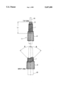
the sole FIGURE is an elevational view, cut away in part, showing the construction and fiber orientation of the layers, in the tip end and grip end portions, of a golf club shaft according to the present invention.
DETAILED DESCRIPTION OF THE PREFERRED EMBODIMENTS OF THE INVENTION
Referring to the FIGURE, designated generally as 11 is a golf club shaft according to one embodiment of the present invention. The shaft 11 in this embodiment is illustrated as being wound on a mandrel 10 having an outer diameter gradually increasing from one end adjacent to a tip end of the shaft 10 to the other end adjacent to a grip end of the shaft 10.
The shaft 11 has an inner tubular layer 1 formed of a hardened, first carbon fiber-reinforced plastic and extending continuously between the tip end and the grip end thereof. The inner layer 1 contains a first carbon fiber group oriented at an angle θ in the range of 40 to 50 degrees with respect to the longitudinal axis of the shaft 11. Preferably, the inner layer 1 is formed of two kinds of wound layers each of which has the same filament orientation angle but which have filament orientation directions opposite to each other with respect to the longitudinal axis of the shaft as shown in the FIGURE. In the present specification and claims, the orientation angle of the fibers (e.g. θ of the first carbon fibers of the inner layer) is indicated in terms of an absolute value, so that, for example, θ of 45° indicates either of the positive and negative positions (±45°) relative to the axis of the shaft.
The first carbon fiber from which the inner layer 1 is formed is a high modulus carbon fiber having a modulus of 29,000 kgf/mm2 or more, preferably 40,000 kgf/mm2 or more and a tensile strength of 300 kgf/mm2 or more, preferably 350 kgf/mm2 or more. The elongation of the first carbon fiber is generally 0.5-1.8%, preferably 0.5-1.0%. Illustrative of suitable high modulus carbon fibers are those commercially available under the trade names of T800, M30S, M40J, M46J, M50J, M55J, M60J and M65J (products by Toray Kabushiki Kaisha) and HMS-40, HMS-46, HMS-55 and HMS-63 (products of Tohoh Rayon Kabushiki Kaisha) and IM-400, IM-600, UM-40, UM-46, UM-55, UM-63 and UM-68 (products of Tohoh Rayon Kabushiki Kaisha).
The inner layer 1 generally has a carbon fiber content of 65-80% by weight, preferably 70-76% by weight. In terms of volumetric percentage, the carbon fiber content is generally 55-75% by volume, preferably 60-70% by volume. The plastic material used as a binder or matrix resin for the first carbon fiber is generally a thermosetting resin such as an epoxy resin or an unsaturated polyester resin. An epoxy resin is preferably used. The inner layer 1 is formed by a sheet winding method using a prepreg containing the first carbon fibers uniaxially oriented within a matrix of a hardenable resin composition.
Provided around the inner layer 1 is an outer tubular layer 2 extending throughout the length the shaft 11 and formed of a hardened, second carbon fiber-reinforced plastic. The outer layer 2 contains a second carbon fiber group oriented at an angle in the range of 5 to 30 degrees with respect to the longitudinal axis of the shaft 11. Preferably, the outer layer 2 is formed of a plurality of wound layers arranged such that the orientation angle the carbon fiber groups of respective layers relative to the longitudinal axis of the shaft is the same but the orientation directions of the fiber groups of each adjacent two layers are opposite to each other with respect to the longitudinal axis of the shaft as shown in the FIGURE.
The second carbon fiber from which the outer layer 2 is formed is a high modulus and high strength carbon fiber having a modulus of 24,000 kgf/mm2 or more, preferably 30,000 kgf/mm2 or more, and a tensile strength of 450 kgf/mm2 or more, preferably 550 kgf/mm2 or more. The elongation of the second carbon fiber is generally 0.8-2.1%, preferably 1.0-2.1%. Illustrative of suitable high modulus carbon fibers are those commercially available under the trade names of T700S, T800, M30S, M35J, M40J and M46J (products by Toray Kabushiki Kaisha) and HMS-40, HMS-46, HMS-55 and HMS-63 (products of Tohoh Rayon Kabushiki Kaisha) and UT-500, IM-400, IM-600, UM-40 and UM-46 (products of Tohoh Rayon Kabushiki Kaisha).
The outer layer 2 generally has a carbon fiber content of 65-80% by weight, preferably 67-75% by weight. In terms of volumetric percentage, the carbon fiber content is generally 55-70% by volume, preferably 58-67% by volume. The plastic material used as a binder or matrix resin for the second carbon fiber is generally a thermosetting resin such as an epoxy resin or an unsaturated polyester resin. An epoxy resin is preferably used. The outer layer 2 is formed by a filament winding method using a tow or roving of the second carbon fibers impregnated with a hardenable resin composition.
Designated as 3 is a tubular reinforcing layer provided inside of the inner layer 1 and extending from the tip end of the shaft through a length L1 of 50 to 500 mm, preferably 100-300 mm. The reinforcing layer 3 is formed of a fiber-reinforced plastic containing reinforcing fiber group oriented at an angle in the range of 0 to 5 degrees with respect to the longitudinal axis of the shaft 11. The reinforcing layer 3 serves to improve the bending modulus and impact resistance of the shaft 11.
The fiber from which the reinforcing layer 3 is formed is a high strength fiber such as a carbon fiber, a boron fiber, titanium fiber, an aromatic polyamide fiber or a polyethylene fiber. These fibers may be used by themselves or as a mixture or in combination of two or more. A carbon fiber is preferably used. The reinforcing fiber has a modulus of 20,000 kgf/mm2 or more, preferably 23,000 kgf/mm2 or more, and a tensile strength of 400 kgf/mm2 or more, preferably 500 kgf/mm2 or more. The elongation of the reinforcing fiber is generally 1.5-2.1%, preferably 1.8-2.1%.
The reinforcing layer 3 generally has a fiber content of 65-76% by weight, preferably 67-70% by weight. In terms of volumetric percentage, the carbon fiber content is generally 55-70% by volume, preferably 58-62% by volume. The plastic material used as a binder or matrix resin for the reinforcing fiber is generally a thermosetting resin such as an epoxy resin or an unsaturated polyester resin. An epoxy resin is preferably used. The reinforcing layer 3 is formed by a sheet winding method using a prepreg containing the reinforcing fibers uniaxially oriented within a matrix of a hardenable resin composition.
The weight ratio of the inner layer 1 to the outer layer 3 should be in the range of 20:80 to 55:45, preferably 30:70 to 45:55. The thickness ratio of the inner layer 1 to the outer layer 3 should be in the range of 1:3 to 1:1, preferably 2:5 to 2:3. A weight ratio in excess of 55:45 or a thickness ratio in excess of 1:1 is undesirable because the weight of the shaft increases and the uniformity of the bending modulus (flexural rigidity) of the shaft in the circumferential direction is lost. When the weight ratio is smaller than 20:80 or when the thickness ratio is smaller than 1:3, on the other hand, the torsional rigidity, bending modulus and buckling strength of the shaft are lowered.
The proportion of the reinforcing layer 3 in the shaft 11 is generally 5-25% by weight, preferably 10-25% by weight. In other words, the total weight of the inner layer 1 and the outer layer 2 is generally 75-95% by weight, preferably 75-90% by weight, based on the weight of the shaft 11. The total carbon fiber content of the shaft 11 is generally 65-75% by volume, preferably 65-70% by volume.
The length of the shaft of the present invention is generally 41-46 inches. The tip end of the shaft has an inside diameter of 2-6 mm, preferably 3-4 mm and a wall thickness of 1.2-3.2 mm, preferably 1.7-2.7 mm, while the grip end has an inside diameter of 11.5-14.5 mm, preferably 12.5-13.5 mm and a wall thickness of 0.5-2.0 mm, preferably 0.7-1.5 mm.
The golf club shaft 11 according to the present invention may be produced by the following method.
First, a prepreg sheet (first prepreg) containing uniaxially oriented reinforcing fibers is cut from a stock material for the reinforcing layer 3 to the desired pattern and is wound around an axially elongated mandrel 10 having an outer diameter gradually increasing from one end thereof to the other end thereof. The prepreg is cut so that the wound prepreg has an axial length of about 50-500 mm and the reinforcing fibers are oriented at an angle in the range of 0 to 5 degrees with respect to the axis of the mandrel 10. The size is determined by the number of convolutions of the material that is to be wound around the mandrel 10. The number of convolutions is determined by the weight and the thickness of the reinforcing layer 3 of the ultimate shaft 11.
Next, at least one sheet of a second prepreg containing uniaxially oriented first carbon fibers is wound around the mandrel for the formation of the inner layer 1. Thus, a prepreg sheet is cut from a stock material for the inner layer 3 to the desired pattern and is wound the mandrel 10. The prepreg is cut so that the wound prepreg has an axial length generally slightly greater than that of the ultimate shaft 11 and the first carbon fibers are oriented, when wound around the mandrel 10, at an angle in the range of 40 to 50 degrees with respect to the axis thereof. The size is determined by the number of convolutions of the material that is to be wound around the mandrel 10.
As described previously, it is preferred that the inner layer 1 be formed of two different kinds of wound layers. In this case, two, first and second kinds of prepreg sheets having, for example, ±45° filament orientations are used. In winding, the first and second prepregs may be alternately wound each through one complete convolution until the desired thickness is reached. Alternatively, the first prepreg (+45°) may be wound through a desired number of convolutions, with the second prepreg (-45°) being subsequently wound through the same number of convolutions.
The thus formed first and second wound layers (which are precursors of the reinforcing layer 3 and the inner layer 1, respectively) are then hardened so that the reinforcing layer 3 of the hardened first resin reinforced with the reinforcing fibers and the inner layer 1 of the hardened second resin reinforced with the first carbon fibers are formed around the mandrel 10. The hardening is generally performed by heating at a temperature of 120°-150° C. for 2-4 hours. Prior to heating, it is preferred that the wound prepreg layers be held in position around the mandrel 10 by winding a tape, formed of, for example, a polypropylene, polyester or poly(vinyl fluoride) film, in the conventional manner.
Then, a roving or tow of second carbon fibers impregnated with a hardenable resin is wound by a filament winding method around the hardened inner layer 1 supported by the mandrel 10 to form a third wound layer (a precursor of the outer layer 2) extending to entirely cover the inner layer 1 with the second carbon fibers being oriented at an angle in the range of 5 to 30 degrees with respect to the axis of the mandrel. Preferably, the roving is wound from one end to the other end with an orientation angle in the range of +5° to +30° and then from the other end to the one end at an orientation angle in the range of -5° to -30°. Such reciprocal winding operation is continued until the wound layer has the desired thickness. It is important that the hardening of the reinforcing layer 3 and the inner layer 1 should be performed before the formation of the outer layer 2 since otherwise the fibers of the reinforcing layer 3 and the inner layer 2 would be partially loosened so that the orientation thereof would be disordered and voids would be formed within the inner and reinforcing layers. This follows that the mechanical strengths as well as the uniformity in bending characteristics around the circumference of the ultimate shaft are adversely affected.
The third wound layer thus formed is then hardened in the same manner as the first and second wound layers to form an outer layer of the hardened third resin reinforced with the second carbon fibers. Then, the mandrel 10 is removed to leave a shaft composed of the reinforcing layer 3, the inner layer 1 and the outer layer 2. The both ends of the shaft are cut to adjust the length thereof to a predetermined value and the outer surface of the shaft is ground to a predetermined diameter, thereby to obtain the ultimate shaft 11.
The following examples will further illustrate the present invention.
EXAMPLE 1
A stainless steel mandrel having a length of 1143 mm and diameters at the smaller diameter and larger diameter ends of 4.0 mm and 13.0 mm, respectively, was coated with a silicone lubricant. A prepreg sheet containing uniaxially aligned carbon fiber filaments impregnated with an epoxy resin composition was then wound on the smaller diameter end portion of the mandrel with the direction of the carbon fiber filament being oriented in substantially parallel with the longitudinal axis of the mandrel (namely, the carbon fibers are oriented at an angle of about 0 degree with respect to the axis of the mandrel) to form a wound reinforcing layer having a length of 250 mm (from the tip end of the shaft). The prepreg sheet used was a commercially available one (P3052S-15 manufactured by Toray Kabushiki Kaisha) having a thickness of 0.15 mm, a carbon fiber weight of 150 g/m2, a resin content of 33% by weight (fiber content: 67% by weight) and a carbon fiber content of 58% by volume. The carbon fiber of the prepreg sheet had a modulus of 23,500 kgf/mm2, a tensile strength of 490 kgf/mm2 and an elongation of 2.1%. The prepreg was wound around the mandrel so that the number of the convolutions was 1 (1 ply) at the larger diameter end (250 mm away from the tip end) and was 3.8 (3.8 plies) at the smaller diameter end.
Two kinds of prepreg sheets A-1 and A-2 were cut from a prepreg stock (P9055F-08 manufactured by Toray Kabushiki Kaisha) which contained uniaxially aligned carbon fiber filaments impregnated with an epoxy resin composition and which had a thickness of 0.06 mm, a carbon fiber weight of 75 g/m2, a resin content of 24% by weight (fiber content: 76% by weight) and a carbon fiber content of 69% by volume. The carbon fiber of the prepreg stock had a modulus of 38,500 kgf/mm2, a tensile strength of 450 kgf/mm2 and an elongation of 1.0%. The prepreg sheets A-1 and A-2 had the same size but the orientation direction of the carbon fibers were opposite to each other. The prepreg sheet A-1 was wound around the mandrel throughout the length thereof with the direction of the carbon fiber filament being oriented at an angle of +45 degrees with respect to the axis of the mandrel and with the number of the convolutions being 2 (2 plies) at the larger diameter end and 3 (3 plies) at the smaller diameter end. Then the prepreg sheet A-2 was wound around the wound A-1 sheet throughout the length thereof with the direction of the carbon fiber filament being oriented at an angle of -45 degrees with respect to the axis of the mandrel and with the number of the convolutions being 2 (2 plies) at the larger diameter end and 3 (3 plies) at the smaller diameter end, thereby to form a wound inner layer.
A polypropylene film tape was then wound around the inner layer and the resulting assembly was heated at 130° C. for 2 hours to completely cure the reinforcing layer and the inner layer. The polypropylene tape was then removed.
A tow of carbon fibers (IM-600-12K manufactured by Tohoh Rayon Kabushiki Kaisha, filament number: 12,000, filament diameter: 5 μm) was impregnated with a hardenable epoxy resin composition and then wound around the hardened inner layer at a winding angle of +10° from the smaller diameter end to the larger diameter end and at a winding angle of -10° from the larger diameter end to the smaller diameter end. Such reciprocal winding was continued until the outer diameters of the resulting outer layer at the smaller and larger diameter ends became slightly larger than 8.5 mm and 15 mm, respectively. The tow used had a resin content of 30% by weight (fiber content: 70% by weight) and a carbon fiber content of 61% by volume. The carbon fiber of the tow had a modulus of 29,000 kgf/mm2, a tensile strength of 590 kgf/mm2 and an elongation of 2.0%.
A polypropylene film tape was then wound around the outer layer and the resulting assembly was heated at 130° C. for 2 hours to completely cure the outer layer. After being cooled to room temperature, the mandrel was removed and the polypropylene tape was removed. The resulting shaft was sanded to form a golf club shaft having a length of 1143 mm (45 inches), a tip end outside diameter of 8.5 mm and a grip end outside diameter of 15 mm, a weight of 57 g, a weight ratio of the inner layer to the outer layer of 37:63, a thickness ratio of the inner layer to the outer layer of 10:17, a weight of the reinforcing layer of 6% by weight based on the total weight of the shaft and a total fiber content of 65% by volume.
COMPARATIVE EXAMPLE 1
Example 1 was repeated in the same manner as described except that the outer layer was formed by a sheet winding method in place of the filament winding method. Thus, a prepreg sheet containing uniaxially aligned carbon fiber filaments impregnated with an epoxy resin composition was wound around the hardened inner layer throughout the length thereof with the direction of the carbon fiber filament being oriented in substantially parallel with the longitudinal axis of the mandrel (namely, the carbon fibers are oriented at an angle of about 0 degree with respect to the axis of the mandrel) to form a wound outer layer. The prepreg sheet used was a commercially available one (P3052S-17 manufactured by Yoray Kabushiki Kaisha) having a thickness of 0.17 mm, a carbon fiber weight of 175 g/m2 resin content of 33% by weight (fiber content: 67% by weight) and a carbon fiber content of 59% by volume. The carbon fiber of the prepreg sheet had a modulus of 30,000 kgf/mm2, a tensile strength of 560 kgf/mm2 and an elongation of 1.8%. The prepreg was wound around the mandrel so that the number of the convolutions was 3 throughout the length thereof. The resulting golf club shaft had a weight of 56 g, a weight ratio of the inner layer to the outer layer of 37:63, a thickness ratio of the inner layer to the outer layer of 10:17, a weight of the reinforcing layer of 6% by weight based on the total weight of the shaft and a total fiber content of 64% by volume.
COMPARATIVE EXAMPLE 2
Example 1 was repeated in the same manner as described except that the inner layer was formed by a filament winding method in place of the sheet winding method. Thus, a tow of carbon fibers (UM40-12K manufactured by Tohoh Rayon Kabushiki Kaisha) was impregnated with a hardenable epoxy resin composition and then wound around the hardened inner layer at a winding angle of +45° from the smaller diameter end to the larger diameter end and at a winding angle of -45° from the larger diameter end to the smaller diameter end. Such reciprocal winding was continued until the outer diameters of the resulting outer layer at the smaller and larger diameter ends became 4.8 mm and 13.3 mm, respectively. The tow used had a resin content of 24% by weight (fiber content: 76% by weight) and a carbon fiber content of 69% by volume. The carbon fiber of the tow had a modulus of 39,000 kgf/mm2, a tensile strength of 500 kgf/mm2 and an elongation of 1.2%. The resulting golf club shaft had a weight of 57 g, a weight ratio of the inner layer to the outer layer of 37:63, a thickness ratio of the inner layer to the outer layer of 10:17, a weight of the reinforcing layer of 6% by weight based on the total weight of the shaft and a total fiber content of 65% by volume.
COMPARATIVE EXAMPLE 3
Example 1 was repeated in the same manner as described except that the wound reinforcing layer and the inner layer were not cured before the winding of the outer layer. Thus, the hardening of the reinforcing layer, inner layer and outer layer was simultaneously performed after the winding of the outer layer. The resulting golf club shaft had a weight of 56 g, a weight ratio of the inner layer to the outer layer of 37:63, a thickness ratio of the inner layer to the outer layer of 10:17, a weight of the reinforcing layer of 6% by weight based on the total weight of the shaft and a total fiber content of 65% by volume.
The thus obtained golf club shafts were tested for their mechanical properties. Test methods are as follows:
Bending Destruction Test
Sample shaft is inserted through a length of 38 mm from the tip end into a horizontally extending hole of a jig having a shape similar to a head hosel and firmly fixed therein, with the grip end being maintained free. A load is vertically applied at a rate of 5 mm/cm to the shaft at a position 102 mm away from the fixed point until breakage. The load which has caused breakage is measured.
Izod Impact Strength Test
Sample shaft is cut at 60 mm from the tip end thereof. The cut sample is vertically held by firmly nipping the lower half portion thereof. The izod impact strength is measured in accordance with JIS K7110. A hammer whose shaft is swingably supported above the sample is allowed to swing from a predetermined height to hit the sample. The loss of the energy of the hammer caused by the hitting of the sample is measured.
Torque Destruction Test
Sample shaft is firmly gripped at both ends (length: 40 mm) with a pair of jigs. One of the jig on the tip end side is rotated about the axis of the shaft with the other jig being maintained unmoved. The torque which caused breakage of the shaft is measured.
Bending Rigidity Test
Sample shaft is horizontally supported at two positions 15 mm and 180 mm away from the grip end thereof, respectively. A load is then vertically applied at a point 925 mm away from the grip end until that point is lowered through a distance of 165 mm. The load required for lowering the load-applying point through 165 mm is measured. The test is performed at two different positions (0° and 90°) around the circumference of the shaft.
Frequency
Sample shaft is firmly secured at a position 83 mm away from the grip end thereof. A model head weighing 285 g is fixed to the tip end and excited to freely oscillate. The frequency (cycles per minute) is measured using a counter (Precision FM manufactured by Brunswick Inc.). The test is performed at eight different positions (0°, 45°, 90°, 135°, 180°, 225°, 270° and 315°) around the circumference of the shaft.
The test results were as summarized in Table below.
As will be seen from the test results, while the shaft of Comparative Example 1 whose outer layer is formed by the sheet winding method shows good mechanical strengths, the bending characteristics vary with the position around the circumference. On the other hand, the shaft of Comparative Example 2 whose inner layer is formed by the filament winding method shows uniform bending characteristics but the mechanical characteristics are unsatisfactory. Neither the uniformity in bending characteristics nor the mechanical properties of the shaft of Comparative Example 3, in which the hardening of the resin is performed only once after the formation of the wound outer layer, are satisfactory. In contrast, the golf club shaft according the present invention exhibits excellent mechanical strengths while maintaining uniform deflection characteristics around the circumference.
The invention may be embodied in other specific forms without departing from the spirit or essential characteristics thereof. The present embodiments are therefore to be considered in all respects as illustrative and not restrictive, the scope of the invention being indicated by the appended claims rather than by the foregoing description, and all the changes which come within the meaning and range of equivalency of the claims are therefore intended to be embraced therein.
______________________________________                                    
Example         1                                                         
Comparative Example     1        2     3                                  
Bending Destruction Test                                                  
                41      40       30    35                                 
(kg)                                                                      
Izod Impact Strength Test                                                 
                125     135      120   125                                
(kg/cm)                                                                   
Torque Destruction Test                                                   
                178     180      130   165                                
(kg/cm)                                                                   
Bending Rigidity Test (kg)                                                
0°       13.5    13.8     13.2  12.5                               
90°      13.6    13.2     13.2  13.2                               
Frequency (cpm)                                                           
0°       208.3   211.4    205.1 206.1                              
45°      208.8   209.5    205.2 201.9                              
90°      208.5   205.3    204.9 198.2                              
135°     207.2   207.2    205.1 200.7                              
180°     207.6   207.3    205.4 208.4                              
225°     207.9   209.5    205.4 202.5                              
270°     207.6   206.1    205.1 197.8                              
315°     208.1   208.8    205.5 201.4                              
______________________________________                                    

Claims (2)

What is claimed is:
1. A golf club shaft having a grip end, a tip end, an outer diameter gradually decreasing from said grip end to said tip end, and an average weight of not greater than 1.4 g per inch, said shaft comprising:
an inner tubular layer formed of a hardened, first carbon fiber-reinforced plastic and extending continuously throughout the length of said shaft, said inner layer containing a first carbon fiber group having a modulus of 29,000 kgf/mm2 or more and a tensile strength of 300 kgf/mm2 or more and oriented at an angle in the range of 40 to 50 degrees with respect to the longitudinal axis of said shaft;
an outer tubular layer provided contiguously around said inner layer throughout the length thereof and formed of a hardened, second carbon fiber-reinforced plastic material, said outer layer containing a second carbon fiber group having a modulus of 24,000 kgf/mm2 or more and a tensile strength of 450 kgf/mm2 or more and oriented at an angle in the range of 5 to 30 degrees with respect to the longitudinal axis of said shaft, and
a tubular, reinforcing layer provided inside of said inner layer and extending from said tip end with a length of 50 to 500 mm, said reinforcing layer being formed of a hardened, reinforcing fiber-reinforced plastic containing a fiber group having a modulus of 20,000 kgf/mm2 or more and a tensile strength of 500 kgf/mm2 or more and oriented at an angle in the range of 0 to 5 degrees with respect to the longitudinal axis of said shaft,
the weight ratio of said inner layer to said outer layer being in the range of 20:80 to 55:45,
the thickness ratio of said inner layer to said outer layer being in the range of 1:3 to 1:1,
said inner layer being obtained from a prepreg sheet containing said first carbon fiber groups dispersed within a matrix of a first hardenable resin,
said reinforcing layer being obtained from a prepreg sheet containing said reinforcing fiber group dispersed within a matrix of a second hardenable resin,
said outer layer being obtained from windings of a roving of said second carbon fiber groups impregnated with a third hardenable resin,
said first and second hardenable resins having been hardened before the winding of said roving.
2. A process for the preparation of a golf club shaft, comprising the steps of:
providing an axially elongated mandrel having an outer diameter gradually increasing from one end thereof to the other end thereof;
winding at least one sheet of a first prepreg, containing uniaxially oriented reinforcing fibers each having a modulus of 20,000 kgf/mm2 and a tensile strength of 500 kgf/mm2 or more and dispersed within a matrix of a first hardenable resin, around said mandrel to form a first wound layer axially extending from a first portion of said mandrel adjacent to said one end to a second portion of said mandrel 50-500 mm away from said first portion with said reinforcing fibers being oriented at an angle in the range of 0 to 5 degrees with respect to the axis of said mandrel;
winding at least one sheet of a second prepreg, containing uniaxially oriented first carbon fibers each having a modulus of 29,000 kgf/mm2 or more and a tensile strength of 300 kgf/mm2 or more and dispersed within a matrix of a second hardenable resin, around said mandrel to form a second wound layer axially extending from said first portion of said mandrel to a third portion of said mandrel adjacent to said the other end thereof with said first carbon fibers being oriented at an angle in the range of 40 to 50 degrees with respect to the axis of said mandrel;
then hardening said first and second wound layers so that a reinforcing layer of the hardened first resin reinforced with said reinforcing fibers and an inner layer of the hardened second resin reinforced with said first carbon fibers are formed around said mandrel;
then winding a roving of second carbon fibers each having a modulus of 24,000 kgf/mm2 and a tensile strength of 450 kgf/mm2 or more and impregnated with a third hardenable resin around said inner layer to form a third wound layer extending to entirely cover said inner layer with said second carbon fibers being oriented at an angle in the range of 5 to 30 degrees with respect to the axis of said mandrel;
then hardening said third wound layer to form an outer layer of the hardened third resin reinforced with said second carbon fibers and to thereby form an integral assembly composed of said reinforcing layer, said inner layer and said outer layer; and
removing said mandrel from said assembly.
US08/297,028 1993-08-31 1994-08-29 Golf club shaft and process of preparing same Expired - Fee Related US5437450A (en)

Applications Claiming Priority (2)

Application Number Priority Date Filing Date Title
JP5-238964 1993-08-31
JP5238964A JP3020222B2 (en) 1993-08-31 1993-08-31 Golf club shaft and method of manufacturing the same

Publications (1)

Publication Number Publication Date
US5437450A true US5437450A (en) 1995-08-01

Family

ID=17037918

Family Applications (1)

Application Number Title Priority Date Filing Date
US08/297,028 Expired - Fee Related US5437450A (en) 1993-08-31 1994-08-29 Golf club shaft and process of preparing same

Country Status (2)

Country Link
US (1) US5437450A (en)
JP (1) JP3020222B2 (en)

Cited By (46)

* Cited by examiner, † Cited by third party
Publication number Priority date Publication date Assignee Title
US5599242A (en) * 1995-02-13 1997-02-04 Taylor Made Golf Company, Inc. Golf club shaft and club including such shaft
US5721030A (en) * 1993-09-03 1998-02-24 Shimano, Inc. Tubular member
US5935017A (en) 1996-06-28 1999-08-10 Cobra Golf Incorporated Golf club shaft
US5961395A (en) * 1997-03-10 1999-10-05 You; Chin-San Golf club
US5984804A (en) * 1996-03-01 1999-11-16 True Temper Sports, Inc. Lightweight shaft and methods of making same
USD418566S (en) * 1997-07-08 2000-01-04 Cobra Golf Incorporated Lower section of a shaft adapted for use in a golf club shaft
US6012777A (en) * 1997-04-29 2000-01-11 Grammer Automotive Gmbh Mount for motor-vehicle headrest
US6117021A (en) 1996-06-28 2000-09-12 Cobra Golf, Incorporated Golf club shaft
GB2323043B (en) * 1997-03-11 2001-02-21 You Chin San Golf club
US6273830B1 (en) * 1996-04-19 2001-08-14 Nippon Mitsubishi Oil Corporation Tapered hollow shaft
US6302806B1 (en) * 1999-02-09 2001-10-16 Patrick C. T. Hsu Shaft of golf club
US6354957B1 (en) * 1997-03-31 2002-03-12 Daiwa Seiko, Inc. Golf club shaft
US6475583B1 (en) * 2000-06-07 2002-11-05 Patrick Hsu Structure of tubular product of fiber composite material
US20030022728A1 (en) * 2001-07-11 2003-01-30 Hiroshi Hasegawa Golf club shaft
US6586110B1 (en) 2000-07-07 2003-07-01 Delphi Technologies, Inc. Contoured metal structural members and methods for making the same
US6602148B2 (en) * 2001-03-16 2003-08-05 Patrick Hsu Golf club shaft
US20030176237A1 (en) * 2002-03-15 2003-09-18 Hitoshi Oyama Golf club shaft
US6641893B1 (en) 1997-03-14 2003-11-04 Massachusetts Institute Of Technology Functionally-graded materials and the engineering of tribological resistance at surfaces
US6666778B2 (en) * 2000-11-24 2003-12-23 Mizuno Corporation FRP golf club shaft
US20040092330A1 (en) * 2002-11-12 2004-05-13 Meyer Jeffrey W. Hybrid golf club shaft
US20040092329A1 (en) * 2002-11-12 2004-05-13 Meyer Jeffrey W. Hybrid golf club shaft
US6821638B2 (en) 2000-07-07 2004-11-23 Delphi Technologies, Inc. Shaped contoured crushable structural members and methods for making the same
US6827656B1 (en) * 1997-01-24 2004-12-07 Hd Golf Development, Inc. Higher overall flex golf shaft
US6866593B1 (en) 2000-06-23 2005-03-15 Harrison Sports, Inc. Golf club shaft having multiple metal fiber layers
US6908401B2 (en) 2001-02-28 2005-06-21 Michael H. L. Cheng Shaft for use in golf clubs and other shaft-based instruments and method of making the same
US6949282B2 (en) 2000-07-07 2005-09-27 Delphi Technologies, Inc. Contoured crushable composite structural members and methods for making the same
US20060058111A1 (en) * 2004-09-14 2006-03-16 Sri Sports Limited Golf club shaft
US20060135282A1 (en) * 2004-12-17 2006-06-22 Integran Technologies, Inc. Article comprising a fine-grained metallic material and a polymeric material
US20060194643A1 (en) * 2005-02-28 2006-08-31 Nelson Precision Casting Co., Ltd. Vibration-absorbing structure for golf club shaft
US7771289B2 (en) 2004-12-17 2010-08-10 Integran Technologies, Inc. Sports articles formed using nanostructured materials
US20100260955A1 (en) * 2009-04-09 2010-10-14 Hiroshi Hasegawa Tubular body and manufacturing method thereof
US20120295730A1 (en) * 2011-05-18 2012-11-22 Hiroshi Hasegawa Golf club
US20120295734A1 (en) * 2011-05-18 2012-11-22 Hiroshi Hasegawa Golf club shaft
US8550564B1 (en) * 2010-04-01 2013-10-08 The Boeing Company Composite seat pan structure for a lightweight aircraft seat assembly
US20140274447A1 (en) * 2013-03-14 2014-09-18 Karsten Manufacturing Corporation Shaft plugs for golf clubs and methods to manufacture golf clubs
US20150038254A1 (en) * 2013-07-31 2015-02-05 Dunlop Sports Co. Ltd. Golf club shaft
DE102016106192B3 (en) * 2016-04-05 2017-06-08 ACS Schaftmanufaktur Germany GmbH Golf club shaft
CN106891541A (en) * 2017-02-23 2017-06-27 武汉理工大学 A kind of ply angles of carbon fiber winding proof to external pressure pipe
US20170259138A1 (en) * 2016-03-14 2017-09-14 Dunlop Sports Co. Ltd. Golf club shaft
US20180214751A1 (en) * 2017-01-31 2018-08-02 Globeride, Inc. Golf club
US10252125B2 (en) * 2015-05-18 2019-04-09 Sumitomo Rubber Industries, Ltd. Golf club shaft
US20220111276A1 (en) * 2019-02-07 2022-04-14 True Temper Sports, Inc. Sports equipment with cut outs formed in outer layer of composite material
US11346499B1 (en) 2021-06-01 2022-05-31 Helicoid Industries Inc. Containers and methods for protecting pressure vessels
US11376812B2 (en) 2020-02-11 2022-07-05 Helicoid Industries Inc. Shock and impact resistant structures
US11852297B2 (en) 2021-06-01 2023-12-26 Helicoid Industries Inc. Containers and methods for protecting pressure vessels
US11952103B2 (en) 2022-06-27 2024-04-09 Helicoid Industries Inc. High impact-resistant, reinforced fiber for leading edge protection of aerodynamic structures

Families Citing this family (1)

* Cited by examiner, † Cited by third party
Publication number Priority date Publication date Assignee Title
JP2006158496A (en) * 2004-12-03 2006-06-22 Yokohama Rubber Co Ltd:The Golf club

Citations (8)

* Cited by examiner, † Cited by third party
Publication number Priority date Publication date Assignee Title
US3313541A (en) * 1963-10-11 1967-04-11 Us Fiberglass Company Golf club including reinforced fiber glass shaft
US3998458A (en) * 1974-07-12 1976-12-21 Hitachi Chemical Company, Ltd. Golf club shaft
US4023801A (en) * 1974-09-24 1977-05-17 Exxon Research And Engineering Company Golf shaft and method of making same
US4135035A (en) * 1976-05-20 1979-01-16 Avco Corporation Laminated composite golf club shaft
US4757997A (en) * 1986-06-06 1988-07-19 Fiber-Speed International, Inc. Golf club shaft and method of manufacture
US5088735A (en) * 1988-09-05 1992-02-18 Ryobi Limited Shaft structure of golf club and production method of the shaft
US5143374A (en) * 1990-02-16 1992-09-01 Somar Corporation Golf club shaft and process for manufacturing same
US5156396A (en) * 1991-08-26 1992-10-20 Somar Corporation Golf club shaft

Patent Citations (8)

* Cited by examiner, † Cited by third party
Publication number Priority date Publication date Assignee Title
US3313541A (en) * 1963-10-11 1967-04-11 Us Fiberglass Company Golf club including reinforced fiber glass shaft
US3998458A (en) * 1974-07-12 1976-12-21 Hitachi Chemical Company, Ltd. Golf club shaft
US4023801A (en) * 1974-09-24 1977-05-17 Exxon Research And Engineering Company Golf shaft and method of making same
US4135035A (en) * 1976-05-20 1979-01-16 Avco Corporation Laminated composite golf club shaft
US4757997A (en) * 1986-06-06 1988-07-19 Fiber-Speed International, Inc. Golf club shaft and method of manufacture
US5088735A (en) * 1988-09-05 1992-02-18 Ryobi Limited Shaft structure of golf club and production method of the shaft
US5143374A (en) * 1990-02-16 1992-09-01 Somar Corporation Golf club shaft and process for manufacturing same
US5156396A (en) * 1991-08-26 1992-10-20 Somar Corporation Golf club shaft

Cited By (68)

* Cited by examiner, † Cited by third party
Publication number Priority date Publication date Assignee Title
US5721030A (en) * 1993-09-03 1998-02-24 Shimano, Inc. Tubular member
US5599242A (en) * 1995-02-13 1997-02-04 Taylor Made Golf Company, Inc. Golf club shaft and club including such shaft
US5984804A (en) * 1996-03-01 1999-11-16 True Temper Sports, Inc. Lightweight shaft and methods of making same
US6273830B1 (en) * 1996-04-19 2001-08-14 Nippon Mitsubishi Oil Corporation Tapered hollow shaft
US6117021A (en) 1996-06-28 2000-09-12 Cobra Golf, Incorporated Golf club shaft
US5935017A (en) 1996-06-28 1999-08-10 Cobra Golf Incorporated Golf club shaft
US6827656B1 (en) * 1997-01-24 2004-12-07 Hd Golf Development, Inc. Higher overall flex golf shaft
US5961395A (en) * 1997-03-10 1999-10-05 You; Chin-San Golf club
GB2323043B (en) * 1997-03-11 2001-02-21 You Chin San Golf club
US6641893B1 (en) 1997-03-14 2003-11-04 Massachusetts Institute Of Technology Functionally-graded materials and the engineering of tribological resistance at surfaces
US6354957B1 (en) * 1997-03-31 2002-03-12 Daiwa Seiko, Inc. Golf club shaft
US6012777A (en) * 1997-04-29 2000-01-11 Grammer Automotive Gmbh Mount for motor-vehicle headrest
USD418566S (en) * 1997-07-08 2000-01-04 Cobra Golf Incorporated Lower section of a shaft adapted for use in a golf club shaft
US6302806B1 (en) * 1999-02-09 2001-10-16 Patrick C. T. Hsu Shaft of golf club
US6475583B1 (en) * 2000-06-07 2002-11-05 Patrick Hsu Structure of tubular product of fiber composite material
US20060211512A1 (en) * 2000-06-23 2006-09-21 Cheng Michael H L Golf club shaft having multiple metal fiber layers
US7497786B2 (en) 2000-06-23 2009-03-03 Harrison Sports, Inc. Golf club shaft having multiple metal fiber layers
US6866593B1 (en) 2000-06-23 2005-03-15 Harrison Sports, Inc. Golf club shaft having multiple metal fiber layers
US6586110B1 (en) 2000-07-07 2003-07-01 Delphi Technologies, Inc. Contoured metal structural members and methods for making the same
US6949282B2 (en) 2000-07-07 2005-09-27 Delphi Technologies, Inc. Contoured crushable composite structural members and methods for making the same
US6893733B2 (en) 2000-07-07 2005-05-17 Delphi Technologies, Inc. Modified contoured crushable structural members and methods for making the same
US6821638B2 (en) 2000-07-07 2004-11-23 Delphi Technologies, Inc. Shaped contoured crushable structural members and methods for making the same
US6666778B2 (en) * 2000-11-24 2003-12-23 Mizuno Corporation FRP golf club shaft
US20060211511A1 (en) * 2001-02-28 2006-09-21 Cheng Michael H Shaft for use in golf clubs and other shaft-based instruments and method of making the same
US6908401B2 (en) 2001-02-28 2005-06-21 Michael H. L. Cheng Shaft for use in golf clubs and other shaft-based instruments and method of making the same
US6602148B2 (en) * 2001-03-16 2003-08-05 Patrick Hsu Golf club shaft
US6875127B2 (en) * 2001-07-11 2005-04-05 Sumitomo Rubber Industries, Ltd. Golf club shaft
US20030022728A1 (en) * 2001-07-11 2003-01-30 Hiroshi Hasegawa Golf club shaft
US20030176237A1 (en) * 2002-03-15 2003-09-18 Hitoshi Oyama Golf club shaft
US6926617B2 (en) * 2002-03-15 2005-08-09 Sri Sports Limited Golf club shaft
US20040092330A1 (en) * 2002-11-12 2004-05-13 Meyer Jeffrey W. Hybrid golf club shaft
US20040092329A1 (en) * 2002-11-12 2004-05-13 Meyer Jeffrey W. Hybrid golf club shaft
US6805642B2 (en) * 2002-11-12 2004-10-19 Acushnet Company Hybrid golf club shaft
US20050107182A1 (en) * 2002-11-12 2005-05-19 Acushnet Company Hybrid golf club shaft
US7404771B2 (en) * 2004-09-14 2008-07-29 Sri Sports Limited Golf club shaft
US20060058111A1 (en) * 2004-09-14 2006-03-16 Sri Sports Limited Golf club shaft
US7553553B2 (en) 2004-12-17 2009-06-30 Integran Technologies, Inc. Article comprising a fine-grained metallic material and a polymeric material
US20080090066A1 (en) * 2004-12-17 2008-04-17 Integran Technologies, Inc. Article comprising a fine-grained metallic material and a polymeric material
US7354354B2 (en) 2004-12-17 2008-04-08 Integran Technologies Inc. Article comprising a fine-grained metallic material and a polymeric material
US20080254310A1 (en) * 2004-12-17 2008-10-16 Integran Technologies, Inc. Article comprising a fine-Grained metallic material and a polymeric material
US20060135282A1 (en) * 2004-12-17 2006-06-22 Integran Technologies, Inc. Article comprising a fine-grained metallic material and a polymeric material
US7771289B2 (en) 2004-12-17 2010-08-10 Integran Technologies, Inc. Sports articles formed using nanostructured materials
US20060194643A1 (en) * 2005-02-28 2006-08-31 Nelson Precision Casting Co., Ltd. Vibration-absorbing structure for golf club shaft
US20100260955A1 (en) * 2009-04-09 2010-10-14 Hiroshi Hasegawa Tubular body and manufacturing method thereof
US8882949B2 (en) * 2009-04-09 2014-11-11 Sri Sports Limited Tubular body and manufacturing method thereof
US8550564B1 (en) * 2010-04-01 2013-10-08 The Boeing Company Composite seat pan structure for a lightweight aircraft seat assembly
US20120295730A1 (en) * 2011-05-18 2012-11-22 Hiroshi Hasegawa Golf club
US8979666B2 (en) * 2011-05-18 2015-03-17 Sri Sports Limited Golf club shaft
US9079083B2 (en) * 2011-05-18 2015-07-14 Dunlop Sports Co. Ltd. Golf club
US20120295734A1 (en) * 2011-05-18 2012-11-22 Hiroshi Hasegawa Golf club shaft
US9895580B2 (en) 2013-03-14 2018-02-20 Karsten Manufacturing Corporation Shaft plugs for golf clubs and methods to manufacture golf clubs
US20140274447A1 (en) * 2013-03-14 2014-09-18 Karsten Manufacturing Corporation Shaft plugs for golf clubs and methods to manufacture golf clubs
US9216325B2 (en) * 2013-03-14 2015-12-22 Karsten Manufacturing Corporation Shaft plugs for golf clubs and methods to manufacture golf clubs
US20150038254A1 (en) * 2013-07-31 2015-02-05 Dunlop Sports Co. Ltd. Golf club shaft
US9498687B2 (en) * 2013-07-31 2016-11-22 Dunlop Sports Co. Ltd. Golf club shaft
US10252125B2 (en) * 2015-05-18 2019-04-09 Sumitomo Rubber Industries, Ltd. Golf club shaft
US20170259138A1 (en) * 2016-03-14 2017-09-14 Dunlop Sports Co. Ltd. Golf club shaft
US10143901B2 (en) * 2016-03-14 2018-12-04 Sumitomo Rubber Industries, Ltd. Golf club shaft
WO2017174049A1 (en) 2016-04-05 2017-10-12 ACS Schaftmanufaktur Germany GmbH Golf club shaft
DE102016106192B3 (en) * 2016-04-05 2017-06-08 ACS Schaftmanufaktur Germany GmbH Golf club shaft
US20180214751A1 (en) * 2017-01-31 2018-08-02 Globeride, Inc. Golf club
US10376759B2 (en) * 2017-01-31 2019-08-13 Globeride, Inc. Golf club
CN106891541A (en) * 2017-02-23 2017-06-27 武汉理工大学 A kind of ply angles of carbon fiber winding proof to external pressure pipe
US20220111276A1 (en) * 2019-02-07 2022-04-14 True Temper Sports, Inc. Sports equipment with cut outs formed in outer layer of composite material
US11376812B2 (en) 2020-02-11 2022-07-05 Helicoid Industries Inc. Shock and impact resistant structures
US11346499B1 (en) 2021-06-01 2022-05-31 Helicoid Industries Inc. Containers and methods for protecting pressure vessels
US11852297B2 (en) 2021-06-01 2023-12-26 Helicoid Industries Inc. Containers and methods for protecting pressure vessels
US11952103B2 (en) 2022-06-27 2024-04-09 Helicoid Industries Inc. High impact-resistant, reinforced fiber for leading edge protection of aerodynamic structures

Also Published As

Publication number Publication date
JP3020222B2 (en) 2000-03-15
JPH0767992A (en) 1995-03-14

Similar Documents

Publication Publication Date Title
US5437450A (en) Golf club shaft and process of preparing same
US5156396A (en) Golf club shaft
JPH09267400A (en) Frp bent pipe
GB2254789A (en) Golf club shaft and process for manufacturing same
US6354960B1 (en) Golf club shaft with controllable feel and balance using combination of fiber reinforced plastics and metal-coated fiber-reinforced plastics
JP3317619B2 (en) Hollow shaft with taper
JP3457872B2 (en) Over hosel type golf club shaft and golf club
JP3692691B2 (en) Fiber reinforced plastic tubular body
JP3508429B2 (en) Fiber reinforced plastic tubular body
JP3712143B2 (en) Manufacturing method of shaft for overhosel type golf club
JPH1015130A (en) Shaft for putter
JP2861447B2 (en) Tapered tubular body
KR100361546B1 (en) Method for shaft produce of golf club
JP3257238B2 (en) Fiber reinforced plastic cylinder
JP4583563B2 (en) Tubular body made of fiber reinforced resin
JPH05305164A (en) Golf shaft
JPH08217896A (en) Prepreg
JP4102487B2 (en) Golf club shaft made of fiber reinforced plastic
KR920002103B1 (en) Golf shaft manufacturing method
JPH0939125A (en) Tubular body of fiber reinforced plastic
JPH05269227A (en) Golf shaft
JP2000051411A (en) Fiber-reinforced plastic shaft for golf club
JPH10272214A (en) Light golf club shaft and golf club using the same
JP2003053852A (en) Tubular object made of carbon fiber reinforced composite material and golf club shaft
JP2020031936A (en) Fiber-reinforced plastic molding article and production method thereof

Legal Events

Date Code Title Description
AS Assignment

Owner name: SOMAR CORPORATION, JAPAN

Free format text: ASSIGNMENT OF ASSIGNORS INTEREST;ASSIGNORS:AKATSUKA, TSUNEO;MOTOKI, YOSHIHIRO;HARADA, TAKASHI;AND OTHERS;REEL/FRAME:007127/0840

Effective date: 19940822

FEPP Fee payment procedure

Free format text: PAYOR NUMBER ASSIGNED (ORIGINAL EVENT CODE: ASPN); ENTITY STATUS OF PATENT OWNER: LARGE ENTITY

FEPP Fee payment procedure

Free format text: PAYER NUMBER DE-ASSIGNED (ORIGINAL EVENT CODE: RMPN); ENTITY STATUS OF PATENT OWNER: LARGE ENTITY

Free format text: PAYOR NUMBER ASSIGNED (ORIGINAL EVENT CODE: ASPN); ENTITY STATUS OF PATENT OWNER: LARGE ENTITY

FEPP Fee payment procedure

Free format text: PAYOR NUMBER ASSIGNED (ORIGINAL EVENT CODE: ASPN); ENTITY STATUS OF PATENT OWNER: LARGE ENTITY

Free format text: PAYER NUMBER DE-ASSIGNED (ORIGINAL EVENT CODE: RMPN); ENTITY STATUS OF PATENT OWNER: LARGE ENTITY

FPAY Fee payment

Year of fee payment: 4

REMI Maintenance fee reminder mailed
LAPS Lapse for failure to pay maintenance fees
STCH Information on status: patent discontinuation

Free format text: PATENT EXPIRED DUE TO NONPAYMENT OF MAINTENANCE FEES UNDER 37 CFR 1.362

FP Lapsed due to failure to pay maintenance fee

Effective date: 20030801