US5371951A - Two-axis inclinometer - Google Patents
Two-axis inclinometer Download PDFInfo
- Publication number
- US5371951A US5371951A US07/862,891 US86289192A US5371951A US 5371951 A US5371951 A US 5371951A US 86289192 A US86289192 A US 86289192A US 5371951 A US5371951 A US 5371951A
- Authority
- US
- United States
- Prior art keywords
- geometrical
- inclination
- inclinometer
- liquid
- array
- Prior art date
- Legal status (The legal status is an assumption and is not a legal conclusion. Google has not performed a legal analysis and makes no representation as to the accuracy of the status listed.)
- Expired - Lifetime
Links
Images


Classifications
-
- G—PHYSICS
- G01—MEASURING; TESTING
- G01C—MEASURING DISTANCES, LEVELS OR BEARINGS; SURVEYING; NAVIGATION; GYROSCOPIC INSTRUMENTS; PHOTOGRAMMETRY OR VIDEOGRAMMETRY
- G01C9/00—Measuring inclination, e.g. by clinometers, by levels
- G01C9/02—Details
- G01C9/06—Electric or photoelectric indication or reading means
-
- G—PHYSICS
- G01—MEASURING; TESTING
- G01C—MEASURING DISTANCES, LEVELS OR BEARINGS; SURVEYING; NAVIGATION; GYROSCOPIC INSTRUMENTS; PHOTOGRAMMETRY OR VIDEOGRAMMETRY
- G01C9/00—Measuring inclination, e.g. by clinometers, by levels
- G01C9/18—Measuring inclination, e.g. by clinometers, by levels by using liquids
- G01C9/20—Measuring inclination, e.g. by clinometers, by levels by using liquids the indication being based on the inclination of the surface of a liquid relative to its container
-
- G—PHYSICS
- G01—MEASURING; TESTING
- G01C—MEASURING DISTANCES, LEVELS OR BEARINGS; SURVEYING; NAVIGATION; GYROSCOPIC INSTRUMENTS; PHOTOGRAMMETRY OR VIDEOGRAMMETRY
- G01C9/00—Measuring inclination, e.g. by clinometers, by levels
- G01C9/02—Details
- G01C9/06—Electric or photoelectric indication or reading means
- G01C2009/066—Electric or photoelectric indication or reading means optical
Abstract
A two-axis inclinometer having an inclination-sensitive ray-deflecting device is described, via which a geometrical figure having at least one angle is projected onto a linear array. In addition to providing high resolution, a large measurement range is also opened up by the special arrangement and configuration of the geometrical figure. X-, Y- and overlapping inclinations can be determined simultaneously using the described inclinometer.
Description
The invention relates to a two-axis inclinometer for measuring inclinations or changes in inclination in two mutually perpendicular directions.
Two-axis inclinometers are used, for example, in geodesy for leveling geodetic measuring instruments. In such inclinometers, an element is provided which changes its position as a function of gravity. A measuring mark is projected above the element onto a positionally stable receiver. A positional variation arising here with respect to a previously adjusted zero point is a measure of the inclination of the instrument.
Such an inclinometer is known from EP 0 161 207 B1. Using slit illumination, a light bundle is projected via a mirror onto a combined glass-liquid prism. The prism has a container filled with silicone oil, the inclination being determined via a reflection at the liquid horizon and projection of the ray onto a light-sensitive array. It is possible to determine only a uniaxial direction of inclination in conjunction with a restricted measurement range using the slit illumination described in the above reference. However, biaxial inclination measurements are necessary with geodetic instruments, in particular.
It is an object of the present invention to develop an inclinometer so as to permit biaxial measurements in conjunction with high measurement accuracy and a wide measurement range.
This object is achieved using an inclinometer for measuring inclinations or changes in inclination in two mutually perpendicular directions. This inclinometer is constructed from a carrier having a geometrical figure, a light source which illuminates the carrier, a linear sensor array, an inclination-sensitive ray-deflecting device and means for projecting the geometrical figure onto the linear sensor array via the inclination-sensitive ray-deflecting device, wherein the geometrical figure has at least two projected portions which intersect the array.
Other objects, features, and advantages of the invention will be apparent from the following description of the preferred embodiments.
The invention is represented in exemplary embodiments and explained in further detail with the aid of accompanying drawings, wherein:
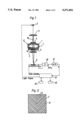
FIG. 1 shows a measuring arrangement having a liquid prism in the transmitted light;
FIG. 2 shows a carrier having a geometrical figure constructed as a herringbone pattern;
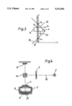
FIG. 3 shows a linear array having an angle of the geometrical figure projected onto it;
FIG. 4 shows a measuring arrangement having a liquid prism and beam splitter;
FIG. 5 shows a measuring arrangement having a liquid prism and total reflection at the liquid horizon;
FIG. 6 shows a measuring arrangement having a filament pendulum;
FIG. 7 shows a carrier having a geometrical figure constructed as a rhomboidal pattern;
FIG. 8 shows a carrier having a geometrical figure constructed as a meandering pattern;
FIG. 9 shows a carrier having a geometrical figure composed of interrupted individual angles; and
FIG. 10 shows an inclined measuring arrangement having a liquid prism in the transmitted light.
FIG. 1 shows an arrangement for a two-axis inclinometer having a light source 2 from which an illuminating ray bundle 10 is projected via a carrier 3 and through a liquid prism 1. A lens system 4 and 5 is arranged in the ray path. The liquid prism 1 has a liquid 6, which preferably consists of transparent silicone oil, in a container 7. The container 7 is closed by a transparent end plate 11. A pattern, such as pattern 12, 17 or 18, shown in FIGS. 2, 8 and 7 respectively, provided on the carrier 3 is projected by the two lenses 4, 5 onto a linear sensor array 8 via the liquid 6. The illuminating ray bundle 10 is collimated in the region of the liquid 6. The arrangement described here can be located both in a dedicated housing and as a component in a geodetic measuring instrument.
In this first embodiment, a deflection of the illuminating ray bundle 10 is performed in the X- and Y-direction by refraction at the inclined liquid horizon 9, the liquid 6 behaving like an optical wedge.
FIG. 2 shows the carrier 3 having arranged thereon a herringbone pattern 12 made of individual angles 13 which are arranged in differing line widths and with irregular spacing from one another on the carrier 3. A larger measurement range for the inclination measurement is achieved by means of this coded arrangement. The evaluation of a biaxial inclination measurement with a 90° angle is explained in more detail with the aid of FIG. 3.
FIG. 3 shows the linear sensor array 8 having an individual angle 13 of the geometrical figure projected onto it. The two legs 15, 16 of the angle 13 intersect CCD 8 at points A1, A2 respectively.
The apex of the angle 13 was projected onto the coordinates X0 and Y0 and an X--Y-coordinate system was fixed computationally with this point as the normal position. This point thus represents the condition of no inclination occurring in the X and Y directions.
An X--Y inclination is determined from the positional deviation of the apex of the angle 13 using the following specified formulae: ##EQU1##
In order to evaluate an inclination in the Y-direction, the angle 13 is displaced on the array 8 along the Y-axis, and thus the apex of the angle 13 is displaced parallel to the array 8. This displacement is determined from the magnitude of the distance YS -YO.
In order to evaluate an inclination in the X-direction the angle 13 is displaced along the X-axis, and thus the apex of the angle 13 is displaced perpendicular to the array 8. This displacement is determined by the magnitude of the distance XS -XO.
In the case of an overlapping movement, that is to say an inclination in both the X- and the Y-direction, the magnitudes of the two displacements resulting therefrom on the array 8 can be determined separately.
In order to simplify the calculation, the angle 13 can be constructed to be 90° (ctg 45°=1). The measuring sensitivity can, however, also be varied by the choice of angle. It becomes clear from the above-mentioned formulae that the sensitivity with respect to a displacement in the x-direction is higher at an angle of α>45° than at α<45°. The measurement range is extended by the use of a geometrical figure such as has already been described in relation to FIG. 2, for example, and it is possible to carry out a plurality of measurements simultaneously for the purpose of error compensation. Depending on the differing line widths and/or the differing spacing of individual angles 13 with respect to one another, each individual angle 13 can be uniquely detected with the aid of this coding and evaluated in a microprocessor 23 shown in FIG. 1.
This microprocessor 23 controls the reading of the inclination sensor 8. Microprocessor 23 outputs signals controlling the strength and duration of the illumination provided by light source 2. Microprocessor 23 also outputs a clock signal to array 8. While array 8 is being illuminated, the corresponding value sensed on a pixel is output as an electrical signal during the clock timing signal. The signal is then amplified by amplifier 26 and converted to a digital signal by A/D converter 27. This digital signal is read in by microprocessor 23 and is temporarily stored in RAM 24 for the further computation of the entire pixel array.
For the evaluation, the positions of the peaks in the pixel image must first be determined. The average center of gravity of the peaks is computed with a calibration constant which is specific for the apparatus and takes into account the index of the liquid 6. The value of the reference position is compared to this result in order to obtain the absolute inclination as an angular value. This value is then displayed on display unit 25.
FIG. 4 shows a further exemplary embodiment having a splitter prism 14. The ray bundle 10 is deflected via this splitter prism 14 and refracted at the liquid horizon 9. A reflection of the image with the geometrical figure is performed at the mirror 21. The reflected image is projected to the array 8 via the prism 14.
FIG. 5 represents an exemplary embodiment having a combined glass-liquid prism 1 which is distinguished by the fact that in conjunction with oblique illumination, the incident illuminating ray bundle 10 is reflected at the liquid horizon 9. As a result, it is possible to achieve a high deflection of the illuminating ray bundle 10 even in the case of small X--Y inclinations.
FIG. 6 shows an exemplary embodiment of the arrangement having a filament pendulum 19 on which the carrier 3 having the geometrical structure is arranged. The carrier 3 is illuminated by a light source 2, and the image is projected onto the linear array 8 arranged below the carrier 3. If the distance between the carrier 3 and the sensor array 8 is chosen as small as possible, the use of additional lenses can be eliminated.
FIG. 7 shows the carrier 3 having arranged thereon a rhomboidal pattern 18 made of individual angles 13. In a manner analogous to the exemplary embodiment of FIG. 2, it is also possible here for the individual angles 13 to be designed with differing line widths.
Represented in FIG. 8 is the carrier 3 having arranged thereon a meandering pattern 17 made of individual angles 13 arranged in a row. In this embodiment, the individual angles 13 can be provided in differing line widths and/or at differing distances from one another on the carrier 3.
FIG. 9 shows a geometrical figure having interrupted individual angles. These angles 22 do not restrict the functioning of the geometrical figure, but limit only the maximum measurement range in the X- or Y-direction.
FIG. 10 shows, in a manner analogous to FIG. 1, an inclined measuring arrangement illuminated by transmitted light. The liquid horizon 9 is aligned in this case under the effect of gravity with respect to the actual horizon 20. This liquid horizon 9, together with the end glass 11, forms an optical wedge at which the collimated illuminating ray bundle 10 is refracted. The projection of the geometrical figure onto the linear sensor array 8 is performed via the lens 5.
The invention is not restricted to geodetic measuring instruments, but can be used as a separate instrument or else in combination with another instrument wherever X--Y inclinations are to be detected.
Other designs within the spirit and scope of the invention will be apparent to those skilled in the field after receiving the above teachings. The invention, therefore, is defined with respect to the following claims.
Claims (5)
1. An inclinometer for measuring inclinations or changes in inclination in two mutually perpendicular directions, comprising:
a geometrical figure arranged on a carrier;
a linear sensor array;
an inclination-sensitive ray-deflecting device, said inclination-sensitive ray-deflecting device being a liquid prism; and
a light source which illuminates said carrier for projecting said geometrical figure onto said linear sensor array via said inclination-sensitive ray-deflecting device, wherein said geometrical figure includes a plurality of lines having differing line thickness forming individual angles arranged one behind another to form a herringbone pattern, said geometrical figure being arranged with respect to said light source and said sensor array such that both sides of at least one of said plurality of angles intersects said array at two points.
2. An inclinometer as recited in claim 1, wherein said liquid prism has transparent silicone oil as its liquid.
3. An inclinometer as recited in claim 1, wherein said carrier is transilluminated by the light source for projecting the geometrical figure onto the array.
4. An inclinometer as recited in claim 1, wherein said geometrical figure is projected by a total reflection at a horizon of a liquid in said liquid prism.
5. An inclinometer as recited in claim 1, further comprising:
means for reading out signals from said array; and
a processing unit receiving said signals and outputting an absolute inclination.
Applications Claiming Priority (2)
| Application Number | Priority Date | Filing Date | Title |
|---|---|---|---|
| DE4110858A DE4110858A1 (en) | 1991-04-04 | 1991-04-04 | TWO-AXIS INCLINATOR |
| DE4110858 | 1991-04-04 |
Publications (1)
| Publication Number | Publication Date |
|---|---|
| US5371951A true US5371951A (en) | 1994-12-13 |
Family
ID=6428792
Family Applications (1)
| Application Number | Title | Priority Date | Filing Date |
|---|---|---|---|
| US07/862,891 Expired - Lifetime US5371951A (en) | 1991-04-04 | 1992-04-06 | Two-axis inclinometer |
Country Status (4)
| Country | Link |
|---|---|
| US (1) | US5371951A (en) |
| EP (1) | EP0507102B1 (en) |
| JP (1) | JP3119715B2 (en) |
| DE (2) | DE4110858A1 (en) |
Cited By (31)
| Publication number | Priority date | Publication date | Assignee | Title |
|---|---|---|---|---|
| US5513001A (en) * | 1992-11-12 | 1996-04-30 | Kabushiki Kaisha Topcon | Tilt angle automatic compensator in all directions |
| EP0802396A2 (en) * | 1996-04-17 | 1997-10-22 | Kabushiki Kaisha Topcon | Inclination sensor and surveying instrument using the same |
| EP0908699A2 (en) * | 1997-10-08 | 1999-04-14 | Kabushiki Kaisha Topcon | Inclination sensor and surveying instrument using the same |
| US5933393A (en) * | 1995-03-02 | 1999-08-03 | Nikon Corporation | Laser beam projection survey apparatus with automatic grade correction unit |
| US5992032A (en) * | 1997-02-24 | 1999-11-30 | Chung-Shan Institute Of Science & Technology | Method and apparatus for inclination measurement using piezoelectric effect |
| GB2343944A (en) * | 1998-11-02 | 2000-05-24 | Zeiss Carl Jena Gmbh | Multi-axis clinometer for measuring gradients and gradient changes |
| US6456194B1 (en) | 2000-09-21 | 2002-09-24 | Craig D. Carlson | Device and method for sensing and indicating inclination of an automotive vehicle |
| US20040083616A1 (en) * | 2002-10-23 | 2004-05-06 | Hamar Laser Instruments, Inc. | Electronic level sensor |
| US20060005407A1 (en) * | 2004-07-12 | 2006-01-12 | Heinz Lippuner | Tilt sensor |
| US20060152710A1 (en) * | 2003-06-23 | 2006-07-13 | Bernhard Braunecker | Optical inclinometer |
| WO2006074929A1 (en) * | 2005-01-12 | 2006-07-20 | Trimble Jena Gmbh | Inclination detection methods and apparatus |
| US20070169362A1 (en) * | 2006-01-24 | 2007-07-26 | Perchak Robert M | Multi-axis bubble vial device |
| US7692777B1 (en) * | 1998-05-04 | 2010-04-06 | Trimble Jena Gmbh | Optical clinometer |
| EP3032219A1 (en) * | 2014-12-09 | 2016-06-15 | Kabushiki Kaisha TOPCON | Tilt detecting device |
| CN106585903A (en) * | 2016-12-19 | 2017-04-26 | 浙江省海洋水产研究所 | Fishing boat for freezing same cabin through vibration energy refrigeration |
| CN106608345A (en) * | 2016-11-23 | 2017-05-03 | 浙江省海洋水产研究所 | Fishing boat with separate type aquatic product refrigerating and freezing mechanism |
| CN106616211A (en) * | 2016-11-23 | 2017-05-10 | 浙江省海洋水产研究所 | Separating type aquatic product refrigeration and freezing mechanism |
| CN106628008A (en) * | 2016-11-23 | 2017-05-10 | 浙江省海洋水产研究所 | Sharing-cabin type aquatic product refrigerating and freezing mechanism |
| CN106741672A (en) * | 2016-12-28 | 2017-05-31 | 浙江海洋大学 | Placement is connected with the ship of the large jellyfish for following the trail of jellyfish vertical movement mechanism |
| CN106800074A (en) * | 2016-12-19 | 2017-06-06 | 浙江省海洋水产研究所 | The fishing boat in the different cabin of vibrational energy refrigeration refrigerating |
| CN106800075A (en) * | 2016-12-19 | 2017-06-06 | 浙江省海洋水产研究所 | The fishing boat of vibrational energy refrigeration cold |
| CN106809349A (en) * | 2016-12-19 | 2017-06-09 | 浙江省海洋水产研究所 | The fishing boat of vibrational energy refrigeration refrigeration |
| CN106828794A (en) * | 2016-12-28 | 2017-06-13 | 浙江海洋大学 | Observe the ship of large jellyfish |
| CN106828852A (en) * | 2016-12-28 | 2017-06-13 | 浙江海洋大学 | Purse seine is casted net ship |
| CN106945797A (en) * | 2016-12-19 | 2017-07-14 | 杭州跟策科技有限公司 | Can seawave power generation be detachably connected wave resistance Crashworthy plate paper bag cargo ship |
| CN106945789A (en) * | 2016-12-19 | 2017-07-14 | 杭州跟策科技有限公司 | If the paper bag cargo ship of paper bag storage rack |
| CN106945798A (en) * | 2016-12-19 | 2017-07-14 | 杭州跟策科技有限公司 | If can wave resistance Crashworthy plate can seawave power generation paper bag cargo ship |
| CN106945790A (en) * | 2016-12-19 | 2017-07-14 | 杭州跟策科技有限公司 | It is detachably connected the paper bag cargo ship of wave resistance Crashworthy plate |
| CN106976529A (en) * | 2016-11-23 | 2017-07-25 | 浙江省海洋水产研究所 | If the fishing boat of common cabin formula aquatic products refrigerating mechanism |
| CN107061119A (en) * | 2016-12-28 | 2017-08-18 | 浙江海洋大学 | Can the purse seine of seawave power generation cast net ship |
| CN109540102A (en) * | 2018-12-14 | 2019-03-29 | 中铁建设集团有限公司 | A kind of high-precision tilt angle measuring device and method based on CCD linear array |
Families Citing this family (1)
| Publication number | Priority date | Publication date | Assignee | Title |
|---|---|---|---|---|
| EP2423640A1 (en) | 2010-08-23 | 2012-02-29 | Hexagon Technology Center GmbH | Inclination sensor for a device and method for determining the inclination of a device |
Citations (21)
| Publication number | Priority date | Publication date | Assignee | Title |
|---|---|---|---|---|
| FR1162059A (en) * | 1955-12-12 | 1958-09-09 | Wild Heerbrugg S A | Method and device for influencing the path of rays in optical instruments |
| CH507506A (en) * | 1970-04-06 | 1971-05-15 | Meier Johann | Pendulum inclinometer |
| US3655274A (en) * | 1970-05-07 | 1972-04-11 | Ingenuics Inc | Gravity operated liquid prism |
| US3684381A (en) * | 1970-03-23 | 1972-08-15 | Ati Inc | Laser beam planar reference |
| US3910704A (en) * | 1973-03-13 | 1975-10-07 | Essilor Int | Compensating device for sighting instruments |
| US4136955A (en) * | 1975-09-02 | 1979-01-30 | Kern & Co. Ag | Apparatus for correcting theodolites |
| US4307516A (en) * | 1980-02-07 | 1981-12-29 | The United States Of America As Represented By The Secretary Of The Army | Directional two-axis differential optical inclinometer |
| US4332090A (en) * | 1980-02-07 | 1982-06-01 | The United States Of America As Represented By The Secretary Of The Army | Directional two axis optical inclinometer |
| JPS5899172A (en) * | 1981-12-07 | 1983-06-13 | 株式会社日立製作所 | Electric insulating silicon carbide sintered body |
| GB2113383A (en) * | 1981-12-24 | 1983-08-03 | Ferranti Ltd | Photoelectric inclination sensor |
| EP0161207A2 (en) * | 1984-05-04 | 1985-11-13 | Kabushiki Kaisha TOPCON | Liquid prism |
| SU1194125A1 (en) * | 1984-04-02 | 1986-09-07 | Предприятие П/Я А-1158 | Device for measuring object slope |
| US4721386A (en) * | 1986-07-18 | 1988-01-26 | Barnes Engineering Company | Three-axis angular monitoring system |
| DE3634244A1 (en) * | 1986-10-08 | 1988-04-21 | Telefunken Electronic Gmbh | Optoelectronic inclination sensor |
| SU1435941A1 (en) * | 1986-05-26 | 1988-11-07 | Устиновский механический институт | Two-coorrdinate inclination angle-data transmitter |
| SU1508096A1 (en) * | 1987-06-12 | 1989-09-15 | Киевский Инженерно-Строительный Институт | Stabilizer of vertical direction of line of sight |
| EP0335117A2 (en) * | 1988-03-30 | 1989-10-04 | Gesellschaft zur Förderung der industrieorientierten Forschung an den Schweizerischen Hochschulen und weiteren Institutionen | Device for detecting positional changes relative to a vertical reference direction in buildings or building soil |
| US4988193A (en) * | 1989-03-01 | 1991-01-29 | Spectra-Physics, Inc. | Method and apparatus for measuring incident light angle relative to level |
| US4993162A (en) * | 1987-07-24 | 1991-02-19 | Kern & Co. Ltd. | Apparatus for measuring inclinations of a component |
| US5035503A (en) * | 1987-01-23 | 1991-07-30 | Yaacov Sadeh | Electro optically corrected coordinate measuring machine |
| US5046843A (en) * | 1989-08-11 | 1991-09-10 | Rotlex Optics Ltd. | Method and apparatus for measuring the three-dimensional orientation of a body in space |
Family Cites Families (2)
| Publication number | Priority date | Publication date | Assignee | Title |
|---|---|---|---|---|
| JPS58190710A (en) * | 1982-04-30 | 1983-11-07 | Mitsubishi Electric Corp | Range finder |
| GB8719154D0 (en) * | 1987-08-13 | 1987-09-23 | Coal Industry Patents Ltd | Optically measuring relative angular movement |
-
1991
- 1991-04-04 DE DE4110858A patent/DE4110858A1/en not_active Withdrawn
-
1992
- 1992-03-06 DE DE59206332T patent/DE59206332D1/en not_active Expired - Fee Related
- 1992-03-06 EP EP92103844A patent/EP0507102B1/en not_active Expired - Lifetime
- 1992-03-30 JP JP04074430A patent/JP3119715B2/en not_active Expired - Lifetime
- 1992-04-06 US US07/862,891 patent/US5371951A/en not_active Expired - Lifetime
Patent Citations (22)
| Publication number | Priority date | Publication date | Assignee | Title |
|---|---|---|---|---|
| FR1162059A (en) * | 1955-12-12 | 1958-09-09 | Wild Heerbrugg S A | Method and device for influencing the path of rays in optical instruments |
| US3684381A (en) * | 1970-03-23 | 1972-08-15 | Ati Inc | Laser beam planar reference |
| CH507506A (en) * | 1970-04-06 | 1971-05-15 | Meier Johann | Pendulum inclinometer |
| US3655274A (en) * | 1970-05-07 | 1972-04-11 | Ingenuics Inc | Gravity operated liquid prism |
| US3910704A (en) * | 1973-03-13 | 1975-10-07 | Essilor Int | Compensating device for sighting instruments |
| US4136955A (en) * | 1975-09-02 | 1979-01-30 | Kern & Co. Ag | Apparatus for correcting theodolites |
| US4307516A (en) * | 1980-02-07 | 1981-12-29 | The United States Of America As Represented By The Secretary Of The Army | Directional two-axis differential optical inclinometer |
| US4332090A (en) * | 1980-02-07 | 1982-06-01 | The United States Of America As Represented By The Secretary Of The Army | Directional two axis optical inclinometer |
| JPS5899172A (en) * | 1981-12-07 | 1983-06-13 | 株式会社日立製作所 | Electric insulating silicon carbide sintered body |
| GB2113383A (en) * | 1981-12-24 | 1983-08-03 | Ferranti Ltd | Photoelectric inclination sensor |
| SU1194125A1 (en) * | 1984-04-02 | 1986-09-07 | Предприятие П/Я А-1158 | Device for measuring object slope |
| EP0161207A2 (en) * | 1984-05-04 | 1985-11-13 | Kabushiki Kaisha TOPCON | Liquid prism |
| SU1435941A1 (en) * | 1986-05-26 | 1988-11-07 | Устиновский механический институт | Two-coorrdinate inclination angle-data transmitter |
| US4721386A (en) * | 1986-07-18 | 1988-01-26 | Barnes Engineering Company | Three-axis angular monitoring system |
| DE3634244A1 (en) * | 1986-10-08 | 1988-04-21 | Telefunken Electronic Gmbh | Optoelectronic inclination sensor |
| US5035503A (en) * | 1987-01-23 | 1991-07-30 | Yaacov Sadeh | Electro optically corrected coordinate measuring machine |
| SU1508096A1 (en) * | 1987-06-12 | 1989-09-15 | Киевский Инженерно-Строительный Институт | Stabilizer of vertical direction of line of sight |
| US4993162A (en) * | 1987-07-24 | 1991-02-19 | Kern & Co. Ltd. | Apparatus for measuring inclinations of a component |
| EP0335117A2 (en) * | 1988-03-30 | 1989-10-04 | Gesellschaft zur Förderung der industrieorientierten Forschung an den Schweizerischen Hochschulen und weiteren Institutionen | Device for detecting positional changes relative to a vertical reference direction in buildings or building soil |
| US4947692A (en) * | 1988-03-30 | 1990-08-14 | Gesellschaft Zur-Forderung der Industrieorientierten Forschung An den Schweizerischen | Apparatus for detecting positional changes in relation to a vertical reference direction in buildings or in building subsoil |
| US4988193A (en) * | 1989-03-01 | 1991-01-29 | Spectra-Physics, Inc. | Method and apparatus for measuring incident light angle relative to level |
| US5046843A (en) * | 1989-08-11 | 1991-09-10 | Rotlex Optics Ltd. | Method and apparatus for measuring the three-dimensional orientation of a body in space |
Non-Patent Citations (2)
| Title |
|---|
| "Micrometertheodolite Wild T1", Prospectus of the WILD Co., pp. 1-16. No date. |
| Micrometertheodolite Wild T1 , Prospectus of the WILD Co., pp. 1 16. No date. * |
Cited By (49)
| Publication number | Priority date | Publication date | Assignee | Title |
|---|---|---|---|---|
| US5513001A (en) * | 1992-11-12 | 1996-04-30 | Kabushiki Kaisha Topcon | Tilt angle automatic compensator in all directions |
| US5933393A (en) * | 1995-03-02 | 1999-08-03 | Nikon Corporation | Laser beam projection survey apparatus with automatic grade correction unit |
| EP0802396A2 (en) * | 1996-04-17 | 1997-10-22 | Kabushiki Kaisha Topcon | Inclination sensor and surveying instrument using the same |
| EP0802396A3 (en) * | 1996-04-17 | 1998-11-25 | Kabushiki Kaisha Topcon | Inclination sensor and surveying instrument using the same |
| US6073355A (en) * | 1997-02-24 | 2000-06-13 | Chung-Shan Institute Of Science & Technology | Method for inclination measurement using piezoelectric effect |
| US5992032A (en) * | 1997-02-24 | 1999-11-30 | Chung-Shan Institute Of Science & Technology | Method and apparatus for inclination measurement using piezoelectric effect |
| EP0908699A3 (en) * | 1997-10-08 | 2000-10-25 | Kabushiki Kaisha Topcon | Inclination sensor and surveying instrument using the same |
| EP0908699A2 (en) * | 1997-10-08 | 1999-04-14 | Kabushiki Kaisha Topcon | Inclination sensor and surveying instrument using the same |
| US7692777B1 (en) * | 1998-05-04 | 2010-04-06 | Trimble Jena Gmbh | Optical clinometer |
| GB2343944A (en) * | 1998-11-02 | 2000-05-24 | Zeiss Carl Jena Gmbh | Multi-axis clinometer for measuring gradients and gradient changes |
| US6320653B1 (en) * | 1998-11-02 | 2001-11-20 | Carl Zeiss Jena Gmbh | Multiple-axis inclinometer for measuring inclinations and changes in inclination |
| GB2343944B (en) * | 1998-11-02 | 2003-05-28 | Zeiss Carl Jena Gmbh | Multi-axis clinometer for measuring gradients and gradient changes |
| US6456194B1 (en) | 2000-09-21 | 2002-09-24 | Craig D. Carlson | Device and method for sensing and indicating inclination of an automotive vehicle |
| US6861949B2 (en) | 2000-09-21 | 2005-03-01 | Craig Carlson | Device and method for sensing and indicating inclination of an automotive vehicle |
| US7298888B2 (en) | 2002-10-23 | 2007-11-20 | Hamar Laser Instruments, Inc. | Electronic level sensor |
| US20040083616A1 (en) * | 2002-10-23 | 2004-05-06 | Hamar Laser Instruments, Inc. | Electronic level sensor |
| US7649621B2 (en) | 2003-06-23 | 2010-01-19 | Leica Geosystems Ag | Optical inclinometer |
| US20060152710A1 (en) * | 2003-06-23 | 2006-07-13 | Bernhard Braunecker | Optical inclinometer |
| US20060005407A1 (en) * | 2004-07-12 | 2006-01-12 | Heinz Lippuner | Tilt sensor |
| US7299557B2 (en) * | 2004-07-12 | 2007-11-27 | Leica Geosystems Ag | Tilt sensor |
| US7688433B2 (en) | 2005-01-12 | 2010-03-30 | Trimble Jena Gmbh | Inclination detection methods and apparatus |
| US7388658B2 (en) * | 2005-01-12 | 2008-06-17 | Trimble Jena Gmbh | Inclination detection methods and apparatus |
| US20090002690A1 (en) * | 2005-01-12 | 2009-01-01 | Andreas Glimm | Inclination detection methods and apparatus |
| WO2006074929A1 (en) * | 2005-01-12 | 2006-07-20 | Trimble Jena Gmbh | Inclination detection methods and apparatus |
| US20060170908A1 (en) * | 2005-01-12 | 2006-08-03 | Andreas Glimm | Inclination detection methods and apparatus |
| US20100195094A1 (en) * | 2005-01-12 | 2010-08-05 | Andreas Glimm | Inclination detection methods and appratus |
| US7973916B2 (en) | 2005-01-12 | 2011-07-05 | Trimble Navigation Limited | Inclination detection methods and apparatus |
| CN101103249B (en) * | 2005-01-12 | 2013-01-02 | 特里伯耶拿有限公司 | Inclination detection methods and apparatus |
| US7497021B2 (en) * | 2006-01-24 | 2009-03-03 | Trimble Navigation Limited | Multi-axis bubble vial device |
| US20070169362A1 (en) * | 2006-01-24 | 2007-07-26 | Perchak Robert M | Multi-axis bubble vial device |
| EP3032219A1 (en) * | 2014-12-09 | 2016-06-15 | Kabushiki Kaisha TOPCON | Tilt detecting device |
| US10088310B2 (en) * | 2014-12-09 | 2018-10-02 | Kabushiki Kaisha Topcon | Tilt detecting device |
| CN106616211A (en) * | 2016-11-23 | 2017-05-10 | 浙江省海洋水产研究所 | Separating type aquatic product refrigeration and freezing mechanism |
| CN106608345A (en) * | 2016-11-23 | 2017-05-03 | 浙江省海洋水产研究所 | Fishing boat with separate type aquatic product refrigerating and freezing mechanism |
| CN106628008A (en) * | 2016-11-23 | 2017-05-10 | 浙江省海洋水产研究所 | Sharing-cabin type aquatic product refrigerating and freezing mechanism |
| CN106976529A (en) * | 2016-11-23 | 2017-07-25 | 浙江省海洋水产研究所 | If the fishing boat of common cabin formula aquatic products refrigerating mechanism |
| CN106800075A (en) * | 2016-12-19 | 2017-06-06 | 浙江省海洋水产研究所 | The fishing boat of vibrational energy refrigeration cold |
| CN106800074A (en) * | 2016-12-19 | 2017-06-06 | 浙江省海洋水产研究所 | The fishing boat in the different cabin of vibrational energy refrigeration refrigerating |
| CN106809349A (en) * | 2016-12-19 | 2017-06-09 | 浙江省海洋水产研究所 | The fishing boat of vibrational energy refrigeration refrigeration |
| CN106945797A (en) * | 2016-12-19 | 2017-07-14 | 杭州跟策科技有限公司 | Can seawave power generation be detachably connected wave resistance Crashworthy plate paper bag cargo ship |
| CN106945789A (en) * | 2016-12-19 | 2017-07-14 | 杭州跟策科技有限公司 | If the paper bag cargo ship of paper bag storage rack |
| CN106945798A (en) * | 2016-12-19 | 2017-07-14 | 杭州跟策科技有限公司 | If can wave resistance Crashworthy plate can seawave power generation paper bag cargo ship |
| CN106945790A (en) * | 2016-12-19 | 2017-07-14 | 杭州跟策科技有限公司 | It is detachably connected the paper bag cargo ship of wave resistance Crashworthy plate |
| CN106585903A (en) * | 2016-12-19 | 2017-04-26 | 浙江省海洋水产研究所 | Fishing boat for freezing same cabin through vibration energy refrigeration |
| CN106828794A (en) * | 2016-12-28 | 2017-06-13 | 浙江海洋大学 | Observe the ship of large jellyfish |
| CN106828852A (en) * | 2016-12-28 | 2017-06-13 | 浙江海洋大学 | Purse seine is casted net ship |
| CN106741672A (en) * | 2016-12-28 | 2017-05-31 | 浙江海洋大学 | Placement is connected with the ship of the large jellyfish for following the trail of jellyfish vertical movement mechanism |
| CN107061119A (en) * | 2016-12-28 | 2017-08-18 | 浙江海洋大学 | Can the purse seine of seawave power generation cast net ship |
| CN109540102A (en) * | 2018-12-14 | 2019-03-29 | 中铁建设集团有限公司 | A kind of high-precision tilt angle measuring device and method based on CCD linear array |
Also Published As
| Publication number | Publication date |
|---|---|
| EP0507102B1 (en) | 1996-05-22 |
| EP0507102A2 (en) | 1992-10-07 |
| JP3119715B2 (en) | 2000-12-25 |
| JPH0599666A (en) | 1993-04-23 |
| DE4110858A1 (en) | 1992-10-08 |
| EP0507102A3 (en) | 1993-01-13 |
| DE59206332D1 (en) | 1996-06-27 |
Similar Documents
| Publication | Publication Date | Title |
|---|---|---|
| US5371951A (en) | Two-axis inclinometer | |
| US6453569B1 (en) | Surveying instrument and plumbing device for plumbing surveying instrument | |
| US4136955A (en) | Apparatus for correcting theodolites | |
| US5949548A (en) | Height sensing measurement device | |
| EP1772703A2 (en) | Position detecting device and inclination sensor device of surveying apparatus using the same, and position measuring method | |
| JP3673954B2 (en) | Tilt sensor and surveying instrument using the same | |
| CN109520446A (en) | A kind of measurement method of revolution at a high speed shafting dynamic inclination error | |
| US4457626A (en) | Apparatus for determining the position of a mark on an object | |
| EP0989387B1 (en) | Laser surveying instrument | |
| US4641961A (en) | Apparatus for measuring the optical characteristics of an optical system to be examined | |
| JPH0345322B2 (en) | ||
| US6320653B1 (en) | Multiple-axis inclinometer for measuring inclinations and changes in inclination | |
| US4097734A (en) | Zero index for electro-optical measuring device | |
| US5383025A (en) | Optical surface flatness measurement apparatus | |
| US4763147A (en) | Special purpose camera | |
| US4600304A (en) | Optical level | |
| JPS63302304A (en) | Sensor integrated with signal processing system for determining position from 1-d to 3-d | |
| CN1076470C (en) | Reflecting liquid wedge compensation system | |
| RU2060461C1 (en) | Code theodolite | |
| JPH0422254Y2 (en) | ||
| SU879541A1 (en) | Photoelectric automatic collimator | |
| SU1060941A1 (en) | Photoelectric device for measuring angular displacements | |
| JPH01233307A (en) | Differential autocollimation sensor | |
| SU1767331A1 (en) | Device for determining horizontal axis deviation of angular instrument | |
| SU1753261A1 (en) | Method to measure right angle of bp-180 @@@ prisms |
Legal Events
| Date | Code | Title | Description |
|---|---|---|---|
| AS | Assignment |
Owner name: LEICA HEERBRUGG AG, SWITZERLAND Free format text: ASSIGNMENT OF ASSIGNORS INTEREST.;ASSIGNOR:PISKE, WILFRIED;REEL/FRAME:006143/0636 Effective date: 19920508 |
|
| STCF | Information on status: patent grant |
Free format text: PATENTED CASE |
|
| FEPP | Fee payment procedure |
Free format text: PAYOR NUMBER ASSIGNED (ORIGINAL EVENT CODE: ASPN); ENTITY STATUS OF PATENT OWNER: LARGE ENTITY |
|
| FPAY | Fee payment |
Year of fee payment: 4 |
|
| FPAY | Fee payment |
Year of fee payment: 8 |
|
| FPAY | Fee payment |
Year of fee payment: 12 |