US5363301A - Control system for vehicle safety device - Google Patents
Control system for vehicle safety device Download PDFInfo
- Publication number
- US5363301A US5363301A US07/837,948 US83794892A US5363301A US 5363301 A US5363301 A US 5363301A US 83794892 A US83794892 A US 83794892A US 5363301 A US5363301 A US 5363301A
- Authority
- US
- United States
- Prior art keywords
- integral value
- acceleration
- deceleration
- signal
- vehicle
- Prior art date
- Legal status (The legal status is an assumption and is not a legal conclusion. Google has not performed a legal analysis and makes no representation as to the accuracy of the status listed.)
- Expired - Fee Related
Links
Images


Classifications
-
- B—PERFORMING OPERATIONS; TRANSPORTING
- B60—VEHICLES IN GENERAL
- B60R—VEHICLES, VEHICLE FITTINGS, OR VEHICLE PARTS, NOT OTHERWISE PROVIDED FOR
- B60R21/00—Arrangements or fittings on vehicles for protecting or preventing injuries to occupants or pedestrians in case of accidents or other traffic risks
- B60R21/01—Electrical circuits for triggering passive safety arrangements, e.g. airbags, safety belt tighteners, in case of vehicle accidents or impending vehicle accidents
- B60R21/013—Electrical circuits for triggering passive safety arrangements, e.g. airbags, safety belt tighteners, in case of vehicle accidents or impending vehicle accidents including means for detecting collisions, impending collisions or roll-over
- B60R21/0132—Electrical circuits for triggering passive safety arrangements, e.g. airbags, safety belt tighteners, in case of vehicle accidents or impending vehicle accidents including means for detecting collisions, impending collisions or roll-over responsive to vehicle motion parameters, e.g. to vehicle longitudinal or transversal deceleration or speed value
- B60R21/0133—Electrical circuits for triggering passive safety arrangements, e.g. airbags, safety belt tighteners, in case of vehicle accidents or impending vehicle accidents including means for detecting collisions, impending collisions or roll-over responsive to vehicle motion parameters, e.g. to vehicle longitudinal or transversal deceleration or speed value by integrating the amplitude of the input signal
-
- B—PERFORMING OPERATIONS; TRANSPORTING
- B60—VEHICLES IN GENERAL
- B60R—VEHICLES, VEHICLE FITTINGS, OR VEHICLE PARTS, NOT OTHERWISE PROVIDED FOR
- B60R21/00—Arrangements or fittings on vehicles for protecting or preventing injuries to occupants or pedestrians in case of accidents or other traffic risks
- B60R21/01—Electrical circuits for triggering passive safety arrangements, e.g. airbags, safety belt tighteners, in case of vehicle accidents or impending vehicle accidents
- B60R21/013—Electrical circuits for triggering passive safety arrangements, e.g. airbags, safety belt tighteners, in case of vehicle accidents or impending vehicle accidents including means for detecting collisions, impending collisions or roll-over
- B60R21/0132—Electrical circuits for triggering passive safety arrangements, e.g. airbags, safety belt tighteners, in case of vehicle accidents or impending vehicle accidents including means for detecting collisions, impending collisions or roll-over responsive to vehicle motion parameters, e.g. to vehicle longitudinal or transversal deceleration or speed value
Definitions
- This invention relates to a control system for a vehicle safety device such as an air bag.
- a control system for an air bag comprises an acceleration sensor, a signal processing circuit, such as a microcomputer, for processing a signal from the acceleration sensor, and a drive circuit for driving the air bag.
- the signal outputted from the acceleration sensor represents one of voltages higher and lower than a reference voltage during the acceleration of a vehicle, and represents the other voltage during the deceleration of the vehicle.
- the microcomputer inputs and integrates the signal from the acceleration sensor at a predetermined cycle, and compares this integral value with a threshold level. This integral value represents a change in the speed of the vehicle, and increases in the decelerating direction upon collision of the vehicle. When the integral value exceeds the threshold level, the microcomputer judges that a collision has occurred, and outputs a trigger signal to the drive circuit to expand the air bag.
- the microcomputer effects the sampling of the sensor signal at predetermined time intervals, and therefore there is a possibility that the sampling of the sensor signal is consecutively effected by accident when the deceleration is large whereas the acceleration is small.
- the absolute value of the signal is very large, the integral value of the sensor signal increases in the decelerating direction, and exceeds the threshold level, thereby inviting an erroneous expansion of the air bag.
- the cycle of the sampling of the sensor signal may be shortened so as to increase the precision of the integral calculation.
- the threshold level is set to a higher level in order to prevent the erroneous expansion of the air bag, it takes long time for the integral value of the deceleration to reach the threshold level when an actual collision occurs, so that the expansion of the air bag is delayed.
- a control system for a vehicle safety device comprising:
- total integral value calculation means for effecting an integral calculation in accordance with the signal from the acceleration sensor to produce a total integral value representative of a change in speed of the vehicle
- deceleration integrating means for integrating the deceleration component of the signal from the acceleration sensor to produce a deceleration integral value
- acceleration integrating means for integrating the acceleration component of the signal from the acceleration sensor to produce an acceleration integral value
- trigger signal outputting means for outputting a trigger signal to the vehicle safety device when the first comparison means judges that the total integral value increasing in the decelerating direction exceeds the threshold level, and at the same time when the second comparison means judges that the deceleration integral value becomes predetermined times greater than the acceleration integral value.
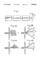
- FIG. 1 is a circuit diagram showing a general construction of a control system of the present invention
- FIG. 2 is a flow chart of a timer interrupt routine executed by a microcomputer
- FIG. 3(A) is a diagrammatical illustration showing a signal of an acceleration sensor upon application of a hammer blow
- FIG. 3(B) is a diagrammatical illustration showing an integral value of the acceleration, an integral value of the deceleration and a total integral value which are calculated based on the signal of FIG. 3(A);
- FIG. 4(A) is a diagrammatical illustration showing a signal of the acceleration sensor upon collision of the vehicle
- FIG. 4(B) is a diagrammatical illustration showing an integral value of the acceleration, an integral value of the deceleration and a total integral value which are calculated based on the signal of FIG. 4(A);
- FIGS. 5 to 7 are flow charts showing a portion of modified interrupt routines, respectively.
- FIG. 8 is a diagrammatical illustration showing a modified threshold level.
- FIG. 1 shows a general construction of a control system for controlling a squib S of an air bag (vehicle safety device).
- This control system comprises an acceleration sensor 10 for outputting a voltage signal in accordance with the acceleration and deceleration of a vehicle, an analog-to-digital converter (ADC) 20 for converting the output voltage signal of the acceleration sensor 10 into digital data, a microcomputer 30 for processing the digital signal from the ADC 20, and a drive circuit 40 for driving the squib S.
- the acceleration sensor 10 outputs the voltage higher than a reference voltage when the vehicle is decelerating, and also outputs the voltage lower than the reference voltage when the vehicle is accelerating.
- ADC analog-to-digital converter
- the drive circuit 40 includes an emitter-grounded transistor 41, and the squib S is connected between the collector of the transistor 41 and a battery V B .
- the transistor 41 is turned on to ignite the squib S, thereby expanding the air bag.
- the microcomputer 30 executes a timer interrupt routine of FIG. 2 at a predetermined cycle (at predetermined time intervals).
- the microcomputer 30 inputs the sensor signal G from the acceleration sensor 10 via the ADC 20 (Step 100).
- the sensor signal G is so converted as to represent the deceleration in terms of a positive value and to represent the acceleration in terms of a negative value.
- Step 101 If the judgment result in Step 101 is "NO", the absolute value
- Step 104 by subtracting the acceleration integral value Vp from the deceleration integral value Vm, a total integral value ⁇ V, representing the amount of change of the vehicle speed, is obtained (Step 104). Then, by dividing the deceleration integral value Vm by the acceleration integral value Vp, an integral value ratio R is obtained (Step 105).
- Step 106 it is judged whether or not the total integral value ⁇ V exceeds a threshold level Th (Step 106). If the judgment result is "NO”, the program returns to a main routine. In contrast, if the judgment result in Step 106 is "YES”, it is judged whether or not the integral value ratio R exceeds a predetermined value ⁇ ( ⁇ >1) (Step 107). If the judgment result in Step 107 is "YES”, the microcomputer 30 outputs the trigger signal to the transistor 41 to expand the air bag (Step 108), and then the program returns to the main routine. If the judgment result in Step 107 is "NO”, the program skips Step 108, and returns to the main routine.
- the trigger signal is not outputted only when the total integral value ⁇ V exceeds the threshold level Th.
- Another requirement for outputting the trigger signal is that the integral value ratio R should exceeds the predetermined value ⁇ , that is to say, that the deceleration integral value Vm should be predetermined times ( ⁇ ) larger than the acceleration integral value Vp. Advantages of this additional requirement will be described with reference to FIGS. 3 and 4.
- the sensor signal G produced upon application of a hammer blow, has a very large amplitude
- the deceleration integral value Vm increases at a higher rate than the acceleration integral value Vp, as indicated in solid lines in FIG. 3B.
- the total integral value ⁇ V tends to increase in the decelerating direction as indicated in a solid line, and may exceed the threshold level Th.
- the ratio R of the deceleration integral value Vm to the acceleration integral value Vp is kept to a relatively small value, and does not exceed the predetermined value ⁇ . Therefore, even if the timing of sampling of the sensor signal is not ideal upon application of the hammer blow, the trigger signal is not outputted, so that an erroneous expansion of the air bag can be positively prevented.
- the sensor signal G produced upon collision of the vehicle, is extremely biased toward the decelerating direction, as shown in FIG. 4A. Therefore, the deceleration integral value Vm is greater than the acceleration integral value Vp, and the difference between the two, that is, the total integral value ⁇ V, becomes large to exceed the threshold level Th, and also the integral value ratio R becomes large to exceed the predetermined value ⁇ . As a result, the trigger signal is outputted to expand the air bag.
- the predetermined value ⁇ is so determined that at the time of the vehicle collision, the integral value ratio R exceeds the predetermined value ⁇ before the total integral value ⁇ V exceeds the threshold level Th.
- Steps 102 to 105 of the routine of FIG. 2 may be replaced by Steps 102A to 105A shown in FIG. 5. More specifically, by adding the sensor signal G, the deceleration integral value Vm is calculated (Step 102A), and also the acceleration integral value Vp is calculated (Step 103A). Therefore, the acceleration integral value Vp represents a negative value.
- the total integral value ⁇ V is obtained by adding the deceleration integral value Vm to the acceleration integral value Vp (Step 104A).
- the integral value ratio R is the absolute value of the value obtained by dividing the deceleration integral value Vm by the acceleration integral value Vp (Step 105A).
- Step 104 of the routine of FIG. 2 may be replaced by Step 104B shown in FIG. 6. More specifically, the total integral value ⁇ V is obtained by adding the sensor signal G to the total integral value ⁇ V obtained at the preceding routine.
- Steps 105 and 107 of the routine of FIG. 2 may be replaced by Steps 105C and 107C shown in FIG. 7.
- An integral value ratio R' is obtained by dividing the acceleration integral value Vp by the deceleration integral value Vm (Step 105C). If it is judged in Step 107C that the integral value ratio R' is below a predetermined value ⁇ ( ⁇ 1), the trigger signal is outputted (Step 108).
- the threshold level Th may be so determined as to decrease as the sensor signal G increases in the decelerating direction.
- the air bag in the case of a strong collision producing a large deceleration, the air bag can be expanded more rapidly because the threshold level is low.
- an erroneous expansion of the air bag can be more positively prevented, because the threshold level is high.
- an erroneous expansion of the air bag upon application of a hammer blow producing the sensor signal with a large amplitude becomes a serious problem; however, this problem can be solved by the above-mentioned additional requirement.
- control system of the present invention can be applied not only to the air bag but also to a pre-tensioner.
Abstract
Description
Claims (5)
Applications Claiming Priority (2)
| Application Number | Priority Date | Filing Date | Title |
|---|---|---|---|
| JP3072179A JP2875040B2 (en) | 1991-03-13 | 1991-03-13 | Vehicle safety device control system |
| JP3-072179 | 1991-03-13 |
Publications (1)
| Publication Number | Publication Date |
|---|---|
| US5363301A true US5363301A (en) | 1994-11-08 |
Family
ID=13481744
Family Applications (1)
| Application Number | Title | Priority Date | Filing Date |
|---|---|---|---|
| US07/837,948 Expired - Fee Related US5363301A (en) | 1991-03-13 | 1992-02-20 | Control system for vehicle safety device |
Country Status (2)
| Country | Link |
|---|---|
| US (1) | US5363301A (en) |
| JP (1) | JP2875040B2 (en) |
Cited By (8)
| Publication number | Priority date | Publication date | Assignee | Title |
|---|---|---|---|---|
| EP0725741A1 (en) * | 1994-08-31 | 1996-08-14 | Automotive Systems Laboratory Inc. | System and method for reducing erroneous crash discrimination |
| EP0787081A1 (en) * | 1994-10-25 | 1997-08-06 | Automotive Systems Laboratory Inc. | Envelope detector useful in crash discrimination |
| WO1997041008A1 (en) * | 1996-04-26 | 1997-11-06 | Siemens Aktiengesellschaft | System for triggering restraint means in a vehicle |
| US6243633B1 (en) * | 1998-09-04 | 2001-06-05 | Bosch Electronics Corporation | Start controlling method for a passenger protection system, and start controlling system for a passenger protection system, and recording medium for recording start control program for passenger protection system |
| US6278923B1 (en) * | 1998-05-25 | 2001-08-21 | Bosch Electronics Corporation | Start controlling method for a passenger protection system, start controlling system for a passenger protection system, and recording medium for recording a start controlling program for a passenger protection system |
| US6549836B1 (en) | 2000-06-07 | 2003-04-15 | Trw Inc. | Method and apparatus for controlling an actuatable restraint device using a velocity/displacement based safing function with immunity box |
| US20050143886A1 (en) * | 2002-10-01 | 2005-06-30 | Marc Theisen | Method for activating a restraint system in a vehicle |
| US9352337B2 (en) | 2011-12-27 | 2016-05-31 | Korea Institute Of Machinery & Materials | Fixed angle hybrid centrifuge rotor having composite outer portion and penetrating inner portion |
Families Citing this family (4)
| Publication number | Priority date | Publication date | Assignee | Title |
|---|---|---|---|---|
| JP2570916B2 (en) * | 1991-04-15 | 1997-01-16 | 株式会社デンソー | Control device for vehicle safety device |
| JP3159279B2 (en) * | 1993-04-27 | 2001-04-23 | オートリブ・ジャパン株式会社 | Collision sensor |
| JP2941643B2 (en) * | 1994-04-14 | 1999-08-25 | 三菱自動車工業株式会社 | Starting device for occupant protection device |
| JP3335815B2 (en) * | 1995-10-12 | 2002-10-21 | 三菱電機株式会社 | Starting device for occupant protection device |
Citations (10)
| Publication number | Priority date | Publication date | Assignee | Title |
|---|---|---|---|---|
| US3911391A (en) * | 1972-05-05 | 1975-10-07 | Messerschmitt Boelkow Blohm | Apparatus for actuating vehicle safety devices |
| US4410875A (en) * | 1978-03-02 | 1983-10-18 | Johann Spies | Releasing circuit and checking circuit for a motor vehicle safety device |
| US4985835A (en) * | 1988-02-05 | 1991-01-15 | Audi Ag | Method and apparatus for activating a motor vehicle safety system |
| US4994972A (en) * | 1989-11-06 | 1991-02-19 | Trw Technar Inc. | Apparatus and method employing multiple crash evaluation algorithms for actuating a restraint system in a passenger vehicle |
| US5037129A (en) * | 1989-04-06 | 1991-08-06 | Robert Bosch Gmbh | Safety device for vehicle occupants |
| US5040118A (en) * | 1989-11-06 | 1991-08-13 | Trw Technar Inc. | Apparatus and method employing multiple crash evaluation algorithms and evaluation expertise for actuating a restraint system in a passenger vehicle |
| US5129673A (en) * | 1988-03-02 | 1992-07-14 | Robert Bosch Gmbh | Electronic device |
| US5157268A (en) * | 1989-12-20 | 1992-10-20 | Messerschmitt-Boelkow-Blohm Ag | Apparatus for triggering a passive safety device for protecting passengers in a vehicle |
| US5225985A (en) * | 1989-01-24 | 1993-07-06 | Diesel Kiki Co., Ltd. | Vehicle safety device actuating apparatus with adaptive reference level |
| US5262949A (en) * | 1990-02-20 | 1993-11-16 | Zexel Corporation | Control system for vehicle safety device |
-
1991
- 1991-03-13 JP JP3072179A patent/JP2875040B2/en not_active Expired - Lifetime
-
1992
- 1992-02-20 US US07/837,948 patent/US5363301A/en not_active Expired - Fee Related
Patent Citations (10)
| Publication number | Priority date | Publication date | Assignee | Title |
|---|---|---|---|---|
| US3911391A (en) * | 1972-05-05 | 1975-10-07 | Messerschmitt Boelkow Blohm | Apparatus for actuating vehicle safety devices |
| US4410875A (en) * | 1978-03-02 | 1983-10-18 | Johann Spies | Releasing circuit and checking circuit for a motor vehicle safety device |
| US4985835A (en) * | 1988-02-05 | 1991-01-15 | Audi Ag | Method and apparatus for activating a motor vehicle safety system |
| US5129673A (en) * | 1988-03-02 | 1992-07-14 | Robert Bosch Gmbh | Electronic device |
| US5225985A (en) * | 1989-01-24 | 1993-07-06 | Diesel Kiki Co., Ltd. | Vehicle safety device actuating apparatus with adaptive reference level |
| US5037129A (en) * | 1989-04-06 | 1991-08-06 | Robert Bosch Gmbh | Safety device for vehicle occupants |
| US4994972A (en) * | 1989-11-06 | 1991-02-19 | Trw Technar Inc. | Apparatus and method employing multiple crash evaluation algorithms for actuating a restraint system in a passenger vehicle |
| US5040118A (en) * | 1989-11-06 | 1991-08-13 | Trw Technar Inc. | Apparatus and method employing multiple crash evaluation algorithms and evaluation expertise for actuating a restraint system in a passenger vehicle |
| US5157268A (en) * | 1989-12-20 | 1992-10-20 | Messerschmitt-Boelkow-Blohm Ag | Apparatus for triggering a passive safety device for protecting passengers in a vehicle |
| US5262949A (en) * | 1990-02-20 | 1993-11-16 | Zexel Corporation | Control system for vehicle safety device |
Cited By (13)
| Publication number | Priority date | Publication date | Assignee | Title |
|---|---|---|---|---|
| EP0725741A1 (en) * | 1994-08-31 | 1996-08-14 | Automotive Systems Laboratory Inc. | System and method for reducing erroneous crash discrimination |
| EP0725741A4 (en) * | 1994-08-31 | 1997-02-05 | Automotive Systems Lab | System and method for reducing erroneous crash discrimination |
| EP0787081A1 (en) * | 1994-10-25 | 1997-08-06 | Automotive Systems Laboratory Inc. | Envelope detector useful in crash discrimination |
| EP0787081A4 (en) * | 1994-10-25 | 1998-07-15 | Automotive Systems Lab | Envelope detector useful in crash discrimination |
| WO1997041008A1 (en) * | 1996-04-26 | 1997-11-06 | Siemens Aktiengesellschaft | System for triggering restraint means in a vehicle |
| US6278923B1 (en) * | 1998-05-25 | 2001-08-21 | Bosch Electronics Corporation | Start controlling method for a passenger protection system, start controlling system for a passenger protection system, and recording medium for recording a start controlling program for a passenger protection system |
| US6502026B2 (en) | 1998-05-25 | 2002-12-31 | Bosch Electronics Corporation | Start controlling method for a passenger protection system, start controlling system for a passenger protection system, and recording medium for recording a start controlling program for a passenger protection system |
| US6243633B1 (en) * | 1998-09-04 | 2001-06-05 | Bosch Electronics Corporation | Start controlling method for a passenger protection system, and start controlling system for a passenger protection system, and recording medium for recording start control program for passenger protection system |
| US6549836B1 (en) | 2000-06-07 | 2003-04-15 | Trw Inc. | Method and apparatus for controlling an actuatable restraint device using a velocity/displacement based safing function with immunity box |
| US20050143886A1 (en) * | 2002-10-01 | 2005-06-30 | Marc Theisen | Method for activating a restraint system in a vehicle |
| US7933702B2 (en) * | 2002-10-01 | 2011-04-26 | Robert Bosch Gmbh | Method for activating a restraint system in a vehicle |
| US20110254253A1 (en) * | 2002-10-01 | 2011-10-20 | Marc Theisen | Method for activating a restraint system in a vehicle |
| US9352337B2 (en) | 2011-12-27 | 2016-05-31 | Korea Institute Of Machinery & Materials | Fixed angle hybrid centrifuge rotor having composite outer portion and penetrating inner portion |
Also Published As
| Publication number | Publication date |
|---|---|
| JP2875040B2 (en) | 1999-03-24 |
| JPH04287748A (en) | 1992-10-13 |
Similar Documents
| Publication | Publication Date | Title |
|---|---|---|
| US5363301A (en) | Control system for vehicle safety device | |
| US5182459A (en) | Control system for vehicle safety device | |
| US5253173A (en) | Method for evaluating a sensor signal | |
| US5262949A (en) | Control system for vehicle safety device | |
| US5067745A (en) | Air bag ignition control system for automotive vehicle and the method | |
| US5083276A (en) | System for controlling safety device for vehicle | |
| EP0092832A2 (en) | Method and device for stopping vehicle at predetermined position | |
| JPS59210374A (en) | Wheel speed arithmetic device | |
| KR950003708B1 (en) | Crash sensor | |
| US6181998B1 (en) | Start controlling method for a passenger protection system, start controlling system for a passenger protection system, and recording medium for recording a start controlling program for a passenger protection system | |
| US6502026B2 (en) | Start controlling method for a passenger protection system, start controlling system for a passenger protection system, and recording medium for recording a start controlling program for a passenger protection system | |
| JP3387542B2 (en) | Load setting device for railway vehicles | |
| US5418724A (en) | Antiskid control apparatus | |
| US6952636B2 (en) | Method of determining the crash phases relevant to the triggering of a passive safety device in a vehicle | |
| EP1112897B1 (en) | Device for controlling expansion of an air bag apparatus | |
| JP2570916B2 (en) | Control device for vehicle safety device | |
| JPH04146847A (en) | Collision detector for vehicle | |
| US20010007963A1 (en) | Automatic door lock releasing apparatus | |
| JP2789569B2 (en) | Control system for vehicle safety equipment | |
| US6729646B1 (en) | Method and system for controlling a vehicle occupant safety system based on crash severity | |
| US3540779A (en) | Antiskid device for a vehicle braking system | |
| EP0308795B1 (en) | Antiskid control device | |
| JPH0585298A (en) | Action control device for occupant protecting apparatus | |
| KR100229467B1 (en) | Inflator operating method of duplicate air bag | |
| KR100203418B1 (en) | Airbag used duplicate accelerative sensor |
Legal Events
| Date | Code | Title | Description |
|---|---|---|---|
| AS | Assignment |
Owner name: ZEXEL CORPORATION, JAPAN Free format text: ASSIGNMENT OF ASSIGNORS INTEREST.;ASSIGNOR:TAKEUCHI, KUNIHIRO;REEL/FRAME:006019/0247 Effective date: 19920205 |
|
| AS | Assignment |
Owner name: AIRBAG SYSTEMS COMPANY LTD., JAPAN Free format text: ASSIGNMENT OF ASSIGNORS INTEREST;ASSIGNOR:ZEXEL CORPORATION;REEL/FRAME:006663/0690 Effective date: 19930816 |
|
| FEPP | Fee payment procedure |
Free format text: PAYOR NUMBER ASSIGNED (ORIGINAL EVENT CODE: ASPN); ENTITY STATUS OF PATENT OWNER: LARGE ENTITY |
|
| FPAY | Fee payment |
Year of fee payment: 4 |
|
| AS | Assignment |
Owner name: BOSCH ELECTRONICS CORPORATION, JAPAN Free format text: CHANGE OF NAME;ASSIGNOR:AIRBAG SYSTEMS COMPANY LTD.;REEL/FRAME:011412/0378 Effective date: 20001003 |
|
| REMI | Maintenance fee reminder mailed | ||
| LAPS | Lapse for failure to pay maintenance fees | ||
| STCH | Information on status: patent discontinuation |
Free format text: PATENT EXPIRED DUE TO NONPAYMENT OF MAINTENANCE FEES UNDER 37 CFR 1.362 |
|
| FP | Lapsed due to failure to pay maintenance fee |
Effective date: 20021108 |