US5351827A - Returnable packaging system for awnings - Google Patents
Returnable packaging system for awnings Download PDFInfo
- Publication number
- US5351827A US5351827A US08/083,067 US8306793A US5351827A US 5351827 A US5351827 A US 5351827A US 8306793 A US8306793 A US 8306793A US 5351827 A US5351827 A US 5351827A
- Authority
- US
- United States
- Prior art keywords
- tubular members
- support plates
- elongated
- channels
- cart
- Prior art date
- Legal status (The legal status is an assumption and is not a legal conclusion. Google has not performed a legal analysis and makes no representation as to the accuracy of the status listed.)
- Expired - Lifetime
Links
- 238000004806 packaging method and process Methods 0.000 title claims description 16
- 239000004744 fabric Substances 0.000 claims description 6
- 230000002787 reinforcement Effects 0.000 claims 1
- 230000000284 resting effect Effects 0.000 claims 1
- 238000003860 storage Methods 0.000 abstract description 25
- 238000003780 insertion Methods 0.000 description 2
- 230000037431 insertion Effects 0.000 description 2
- 238000004519 manufacturing process Methods 0.000 description 2
- 239000003086 colorant Substances 0.000 description 1
- 230000007613 environmental effect Effects 0.000 description 1
- 229920002457 flexible plastic Polymers 0.000 description 1
- 238000007689 inspection Methods 0.000 description 1
- 239000007788 liquid Substances 0.000 description 1
- 230000007774 longterm Effects 0.000 description 1
- 239000000463 material Substances 0.000 description 1
- 238000000034 method Methods 0.000 description 1
- 238000012986 modification Methods 0.000 description 1
- 230000004048 modification Effects 0.000 description 1
- 230000002035 prolonged effect Effects 0.000 description 1
- 230000001681 protective effect Effects 0.000 description 1
- 230000001012 protector Effects 0.000 description 1
- 230000000717 retained effect Effects 0.000 description 1
- 238000004513 sizing Methods 0.000 description 1
Images


Classifications
-
- B—PERFORMING OPERATIONS; TRANSPORTING
- B61—RAILWAYS
- B61D—BODY DETAILS OR KINDS OF RAILWAY VEHICLES
- B61D45/00—Means or devices for securing or supporting the cargo, including protection against shocks
- B61D45/001—Devices for fixing to walls or floors
- B61D45/003—Fixing of logs, beams, barrels, pipes, or the like
-
- B—PERFORMING OPERATIONS; TRANSPORTING
- B60—VEHICLES IN GENERAL
- B60P—VEHICLES ADAPTED FOR LOAD TRANSPORTATION OR TO TRANSPORT, TO CARRY, OR TO COMPRISE SPECIAL LOADS OR OBJECTS
- B60P7/00—Securing or covering of load on vehicles
- B60P7/06—Securing of load
- B60P7/08—Securing to the vehicle floor or sides
- B60P7/12—Securing to the vehicle floor or sides the load being tree-trunks, beams, drums, tubes, or the like
Definitions
- the present invention pertains to rolled awnings and, more particularly, to a returnable and reusable packaging and storage system for such rolled awnings.
- Rolled awnings are conventionally placed in elongated rigid cardboard tubes to protect them during shipment and storage. Although the cardboard tubes are satisfactory to prevent damage to the awnings, the tubes themselves are rather expensive, and insertion of the awnings into the tubes represents an extra step and additional expense in the manufacture of the awnings. Moreover, since it is undesirable from a cost standpoint to return the empty tubes to the manufacturer, the used cardboard tubes create a disposal problem for the retailer.
- the cardboard shipping tubes and awnings create an inventory and retrieval problem for the retailer. Namely, when a specific awning is desired for purchase or inspection, the particular cardboard tube containing that awning must be located within a stack of tubes and thereafter manually pulled or otherwise removed from the stack of awning shipping tubes to gain access to the desired awning therein. This is not only difficult, but disrupts the order of the remaining shipping tubes and renders inventory control and awning retrieval problematic.
- a reusable and returnable rolled awning transport and storage system is disclosed.
- the system is adapted to support and maintain the awnings in a rolled condition during transport and subsequent storage.
- the system provides a plurality of elongated storage spaces which are easily accessible for placement of awnings therein and removal of awnings therefrom, regardless of the relative vertical position of the storage space.
- the transport and storage system includes one or more independently movable and stackable carts.
- Each cart is capable of holding and supporting a number of rolled awnings.
- the system further provides means for protecting ends of the rolled awnings which extend or project from the cart in a cantilever fashion and for preventing longitudinal movement of the rolled awnings.
- the protecting means are operably associated with the cart, and are adjustable to give access to the cantilever ends of the awnings.
- the packaging and storing system includes a plurality of nestable and stackable awning support plates.
- the plates are received and vertically supported by the cart and cooperate, when in a stacked configuration, to define a series of elongated storage channels for receipt of the awnings.
- the awning support plates vertically support one another such that each rolled awning may be slidably withdrawn from its respective elongated storage channel regardless of the vertical position of the awning or channel within the stack of support plates.
- the awning support plates vertically support each other when in the stacked configuration during transport and storage of the rolled awnings.
- the awning support plates nest with each other to reduce their overall vertical height, which is desirable for long-term storage of the support plates, or for return shipment (i.e., without rolled awnings) of the system to the awning manufacturer.
- the awning support plates support and protect the individual awnings during transport and subsequent storage, and remove the need for individual awning protectors such as cardboard tubes.
- FIG. 1 is a perspective view of the returnable and reusable awning transport and storage system of the present invention
- FIG. 2 is a front elevational view of an awning transport and storage cart in accordance with the present invention
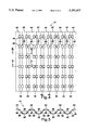
- FIG. 3 is an cross sectional view of the transport and storage cart in accordance with the present invention, as viewed from line 3--3 of FIG. 2, with rolled awnings placed therein;
- FIG. 4 is a top plan view of an awning support plate in accordance with the present invention.
- FIG. 5 is an elevational view of the awning support plate in accordance with the present invention.
- FIG. 6 is an elevational view, in cross section, of the awning support plate, as viewed from line 6--6 of FIG. 4;
- FIG. 7 is an elevational view, in cross section, of the awning support plate, as viewed from line 7--7 of FIG. 4.
- the awning transport and storage system is adapted and arranged to allow the safe and protected transport and storage of a number of rolled awnings 10.
- the rolled awnings which are adapted for use on residential and commercial buildings, as well as on travel trailers, mobile homes, motor homes, and the like, are wrapped or enclosed by a flexible plastic bag (not shown) or other protective material to prevent damage to the awning from liquids and the like.
- the awning transport and storage system generally includes a cart 12, a plurality of awning support plates 14, and a pair of awning end bags or covers 16. As shown best in FIG. 1, the awning end bags 16 attach to opposite ends of the cart 12, and protect and cover ends 17 of the rolled awnings 10 which would otherwise project in an exposed and unprotected manner from the cart 12. The end bags 16 limit axial or longitudinal movement of the awnings 10 which are otherwise free to slide longitudinally along the support plate 14, as will be described more fully hereafter.
- the cart 12 is shown to include a pair of awning support sections 18 and an intermediate, open section 20.
- the awning support sections 18 are adapted to receive and support the awning support plates 14 (FIG. 3).
- the open section 20 includes a series of upper and lower horizontal support members 22 and a pair of widthwise-directed channels 24.
- the upper and lower support members 22 interconnect the awning support sections 18.
- the pair of channels 24 are adapted or arranged to receive forklift forks (not shown) and, preferably, extend the width of the cart 12 to allow a forklift to lift the cart from either side.
- the intermediate section 20 is open at a top, each end, and each lateral side, as illustrated.
- the awning support sections 18 include a bottom panel 26, a pair of vertical support posts 27, a pair of side panels 28, and a series of horizontal support members 29.
- the awning support sections 18 are open at each end and at a top, as illustrated.
- the horizontal support members 29 vertically support the bottom support panel 26.
- Wheels 30 extend downwardly from the awning support sections 18 and allow the cart 12 to be manually pushed or transported, which is helpful in moving the cart when there is no forklift available or when moving with a forklift is not feasible.
- a vertical leg 32 is provided at each corner of the cart 12.
- the legs 32 cooperate with the horizontal support members 29 and the vertical support posts 27 to define a supporting framework for the awning support sections 18.
- the side panels 28 extend between the legs 32 and the vertical support posts 27, as illustrated.
- a lower terminal section 36 of the cart-supporting leg 32 is upwardly spaced a distance D from a bottom of the wheels 30 (i.e., from the support surface), and is of a relatively smaller size than the remainder of the leg 32.
- This smaller lower terminal section 36 is adapted to be received within an enlarged upper terminal section 38 of a downwardly adjacent leg. Receipt of the lower terminal section 36 by the upper terminal section 38 allows the carts to be vertically stacked which is helpful in shipping and storing multiple carts.
- the lower section 36 is upwardly spaced from the support surface to allow the wheels 30 to freely rotate and thereby propel or move the cart without interference from the legs 32.
- the overall length of the cart 12 is about 120 inches.
- Each of the awning support sections 18 is about 36 inches, with about 18 inches being between each of the forklift receiving channels 24.
- the cart also has a width of about 36 inches and a vertical height of about 34 inches.
- the usable height of the cart 12, which is generally equal to the vertical height of the side panels 28 of the awning support sections 18, is about 20 inches.
- the awning support plate 14 is shown to define a wave-like surface.
- the wave-like surface provides a series of lower sections 42 and upper sections 44, the lower and upper sections 42, 44 being connected by intermediate ramping members 46, as illustrated.
- a repeating pattern of lower section 42, ramping section 46, upper section 44, and ramping section 46 is provided by the support plate 14.
- Lower braces 48 connect the ramping members 46 with the lower sections 42, while upper braces 49 connect the ramping members to the upper sections 44.
- the awning support plates 14 are designed to alternatively stack or nest. As illustrated in FIG. 3, when the support plates 14 are in the stacked configuration the lower sections 42 of one support plate abut and rest on the upper sections 44 of a downwardly adjacent awning support plate. Likewise, the upper sections 44 of an awning support plate abut and support the lower sections 42 of an upwardly adjacent awning support plate. As such, the vertically adjacent and stacked awning support plates 14 define a series of elongated awning-receiving channels 50.
- the awning-receiving channels 50 are designed to be slightly larger than the awnings 10 which are placed therein. Sizing of the elongated channels 50 as such allows the awnings 10 to be freely and slidably movable within the channels
- the support plates are preferably placed in a nested configuration for return shipment to the awning manufacturer or for prolonged storage by the awning manufacturer.
- the lower sections 42 of the awning support plates are in contact with the lower braces 48 between a downwardly adjacent lower section 42 and ramping section 46.
- the upper braces 49 are in contact with an upper surface of a downwardly adjacent support plate upper section 44.
- the awning support plates 14 are vertically stacked on the support sections 18 of the cart, leaving the open section 20 therebetween.
- the awnings 10 typically have a length which is greater than that of the cart 12. Therefore, the ends 17 of the awnings 10 extend or project from the elongated channels 50 defined by the awning support plates in an unsupported or cantilever fashion, as illustrated.
- the projecting or cantilever ends 17 of the awnings are covered by the pair of awning end bags 16.
- the end bags 16 limit longitudinal movement of the awnings, and thereby prevent the awnings from sliding out of the elongated channels 50 during transport.
- the awning end bags 16 provided by the present invention comprise a fabric main section 52 and a series of straps
- the straps 54 are provided on opposite sides of the main section 52 and connect to an adjacent vertical leg 32 provided by the cart 12.
- the straps 54 are releasably locked to the vertical legs 32.
- ends of the straps 54 will be locked to the legs 32 by the manufacturer or shipper to prevent the end bags 16 from being accidentally misplaced by the retailer.
- Length adjustment means 56 are provided by the straps 54 to ensure a close supporting fit between the main section 52 and the awning ends 17.
- the length adjustment means 56 also allow the end bags 16 to be removed from the awning ends 17, and thereby provide access to the awnings without unlocking the straps 54 from the legs 32.
- the main fabric section 52 of the awning end bags 16 is designed and dimensioned to generally match the profile of the cantilever or projecting ends 17 of the awnings 10 and, therefore, provides a snug and continuous fit for the awning ends 17.
- the main section 52 which is preferably made of a durable fabric such as canvas, overlies and encloses the projecting ends 17 of the awnings, and helps to prevent damage to the awning ends 17 during shipment and subsequent storage. As shown best in FIG. 1, when the extending straps 54 are drawn tight, the awning end bag 16 engages the cantilever ends 17, and limits or otherwise prevents the awnings 10 from moving longitudinally.
- an awning support plate 14 is placed on the bottom panel 26 of each awning support section 18.
- the awning support plates 14 are positioned and retained between the side panels 28, the cart supporting legs 32, and the vertical support posts 27.
- awnings 10 are placed on the support plates 14 in contact with the bottom section 42 thereof.
- the awnings 10 are received by and extend between the awning support plates 14. If the awnings are long enough, the ends 17 extend or project from the awning support plates 14 in an unsupported or cantilever fashion.
- another or second awning support plate 14 is stacked on the existing plate and awnings 10 are placed on the second support plate 14 in contact with the lower section 42 thereof. The process is repeated until the cart 12 is full.
- the lower sections 42 and adjacent ramping members 46 of one support plate 14 cooperate with upper sections 44 and adjacent ramping members 46 of a vertically adjacent support plate to define the elongated awning-receiving channels 50.
- the upper surfaces of an upper section 44 vertically support and engage lower surfaces of a lower section 42 provided by a vertically adjacent support plate 14.
- the elongated channels 50 are preferably larger in diameter than the awnings 10, thereby allowing any particular awning to be freely and slidably removed from the array of awnings within the system.
- the main section 52 of the awning end bag 16 is fitted or placed over the cantilever ends 17 of the awnings and the removable straps 54 are attached to the legs 32.
- the length adjustment means 56 are adjusted to force the main section 52 to cover or enclose the cantilever ends 17 of the awnings 10, as illustrated in FIG. 1.
- the main section 52 covers and protects the ends 17 of the awnings 10 during shipment and prevents lengthwise or longitudinal movement of the awnings.
- the carts can be vertically stacked upon one another to reduce the floor space required for shipment and storage.
- One cart is lifted, by a forklift or the like, and lowered on a downwardly adjacent supporting cart such that the smaller terminal sections 36 of the lifted cart legs 32 are received by the enlarged upper terminal section 38 of the lower cart legs.
- the wheels of the lifted cart are vertically adjacent or above the awnings carried by the lower cart.
Abstract
Description
Claims (12)
Priority Applications (2)
| Application Number | Priority Date | Filing Date | Title |
|---|---|---|---|
| US08083067 US5351827B1 (en) | 1993-06-25 | 1993-06-25 | Returnable packaging system for awnings |
| US08/534,304 US5516244A (en) | 1993-06-25 | 1995-09-27 | Method of using a returnable packaging system for awnings |
Applications Claiming Priority (1)
| Application Number | Priority Date | Filing Date | Title |
|---|---|---|---|
| US08083067 US5351827B1 (en) | 1993-06-25 | 1993-06-25 | Returnable packaging system for awnings |
Related Child Applications (1)
| Application Number | Title | Priority Date | Filing Date |
|---|---|---|---|
| US29162994A Division | 1993-06-25 | 1994-08-17 |
Publications (2)
| Publication Number | Publication Date |
|---|---|
| US5351827A true US5351827A (en) | 1994-10-04 |
| US5351827B1 US5351827B1 (en) | 1996-10-15 |
Family
ID=22175959
Family Applications (2)
| Application Number | Title | Priority Date | Filing Date |
|---|---|---|---|
| US08083067 Expired - Lifetime US5351827B1 (en) | 1993-06-25 | 1993-06-25 | Returnable packaging system for awnings |
| US08/534,304 Expired - Fee Related US5516244A (en) | 1993-06-25 | 1995-09-27 | Method of using a returnable packaging system for awnings |
Family Applications After (1)
| Application Number | Title | Priority Date | Filing Date |
|---|---|---|---|
| US08/534,304 Expired - Fee Related US5516244A (en) | 1993-06-25 | 1995-09-27 | Method of using a returnable packaging system for awnings |
Country Status (1)
| Country | Link |
|---|---|
| US (2) | US5351827B1 (en) |
Cited By (15)
| Publication number | Priority date | Publication date | Assignee | Title |
|---|---|---|---|---|
| US5452973A (en) * | 1994-12-05 | 1995-09-26 | Arvin; Adrian H. | Truck bed cargo net |
| US5516244A (en) * | 1993-06-25 | 1996-05-14 | The Dometic Corporation | Method of using a returnable packaging system for awnings |
| NL9500529A (en) * | 1995-03-16 | 1996-11-01 | Allseas Group Sa | Vessel |
| USD384481S (en) * | 1996-05-17 | 1997-09-30 | Sheckells Amuel E | Load rack |
| US5957287A (en) * | 1999-01-04 | 1999-09-28 | Armstrong World Industries, Inc. | Roll storage and transport rack |
| US6164883A (en) * | 1998-08-18 | 2000-12-26 | White Consolidated Industries, Inc. | Returnable packaging system for elongated members |
| US6296133B1 (en) | 2000-06-02 | 2001-10-02 | Joseph L. Cobane | Container for vinyl siding |
| US6863482B2 (en) | 2003-06-16 | 2005-03-08 | Fred Lockhart | Cargo retention system |
| US20050074307A1 (en) * | 2003-10-02 | 2005-04-07 | Guarisco Leonard J. | Multilength tubular transporter |
| AU2013100033B4 (en) * | 2013-01-14 | 2015-11-12 | Whites Group Pty Ltd | Pack for fence posts or other elongate objects |
| CN105480564A (en) * | 2015-12-31 | 2016-04-13 | 苏州宝嘉新能源科技有限公司 | Pipe fitting packaging and fixing support assembly facilitating loading, unloading and transporting |
| CN105819121A (en) * | 2016-05-24 | 2016-08-03 | 天津市贤仕运输有限公司 | Device convenient for transporting cargoes |
| US10336356B2 (en) * | 2016-06-22 | 2019-07-02 | Globe Composite Solutions, Ltd. | Wheeled shipping cart with stackable trays |
| US20200087059A1 (en) * | 2015-06-11 | 2020-03-19 | Korea Railroad Research Institute | Foldable container and apparatus for folding and unfolding the same |
| US11318876B2 (en) | 2020-03-25 | 2022-05-03 | Home Depot Product Authority, Llc | Cargo retainer |
Families Citing this family (33)
| Publication number | Priority date | Publication date | Assignee | Title |
|---|---|---|---|---|
| US5755541A (en) * | 1996-05-03 | 1998-05-26 | Inter-American Vanguard Corporation | Drum transport support system |
| US5735412A (en) * | 1996-05-22 | 1998-04-07 | Sheckells; Amuel E. | Self-griping rack and method for stacking articles with rack |
| US5915899A (en) * | 1996-12-05 | 1999-06-29 | Dennis; John G. | End restraint for securing plural elongated items |
| DE29702638U1 (en) * | 1997-02-15 | 1997-04-03 | Thread Guard Technology Ltd | Device for supporting pipes |
| US6065915A (en) * | 1997-03-05 | 2000-05-23 | Ruehl; John W. | Tank storage apparatus |
| US6261037B1 (en) * | 1997-07-25 | 2001-07-17 | Drilltec Patents & Technologies Company, Inc. | Connector assembly |
| JP3796345B2 (en) * | 1998-02-23 | 2006-07-12 | ゼオン化成株式会社 | Rod shipping container |
| US6089802A (en) * | 1998-02-23 | 2000-07-18 | Bullock; Matthew | Cargo restraint system for a transport container |
| US6607337B1 (en) * | 2000-05-05 | 2003-08-19 | Matthew Bullock | Cargo restraint system |
| US6626620B1 (en) * | 2000-12-15 | 2003-09-30 | James B Veal | Load retaining apparatus on a vehicle |
| US6758644B1 (en) | 2001-11-16 | 2004-07-06 | Wayne E. Vick | Composite restraint system for securing freight |
| IL146806A0 (en) * | 2001-11-28 | 2002-07-25 | Moseroth Ltd | Extensible barrier |
| US7591384B2 (en) * | 2002-01-03 | 2009-09-22 | Sheckells Amuel E | Self gripping rack with snap-on flexible strap |
| WO2005063477A1 (en) * | 2003-12-09 | 2005-07-14 | Matthew Bullock | Cargo restraint system and method |
| US7329074B2 (en) * | 2003-12-09 | 2008-02-12 | Matthew Bullock | Cross-weave cargo restraint system and method |
| EP1691972B1 (en) * | 2003-12-09 | 2008-02-27 | Matthew Bullock | Cross-weave cargo restraint system and method |
| US6981827B2 (en) * | 2004-02-05 | 2006-01-03 | Matthew Bullock | Cargo restraint torque apparatus |
| US20060032850A1 (en) * | 2004-08-12 | 2006-02-16 | Theriot Ronald J | Adjustable basket for storing and transporting cargo |
| US20130341227A1 (en) * | 2006-01-20 | 2013-12-26 | Mark Knight | Modular pipe basket |
| US7381020B1 (en) * | 2005-09-20 | 2008-06-03 | Western Tube & Conduit Corporation | Method for loading tube bundles on railcars and tube packs for railcars |
| US7708508B2 (en) * | 2006-07-23 | 2010-05-04 | Matthew Bullock | Adjustable load stabilizer method and apparatus |
| CN201077592Y (en) * | 2007-08-03 | 2008-06-25 | 乔士军 | Packing support |
| WO2009152429A1 (en) | 2008-06-13 | 2009-12-17 | Hill-Rom Services, Inc. | Item support apparatuses and systems for bedside |
| US8128324B2 (en) * | 2009-06-09 | 2012-03-06 | Matthew Bullock | Cargo restraint method with enhanced shear strength |
| US8113752B2 (en) * | 2009-06-18 | 2012-02-14 | Matthew Bullock | Cargo restraint system with enhanced peel strength |
| US20110010854A1 (en) | 2009-07-15 | 2011-01-20 | Zerhusen Robert M | Siderail with storage area |
| US8403607B1 (en) | 2011-10-28 | 2013-03-26 | Matthew Bullock | Cargo restraint system with enhanced reinforcement end filament content |
| US8403609B1 (en) | 2011-10-28 | 2013-03-26 | Matthew Bullock | Cargo restraint system with enhanced reinforcement filament break strength content |
| US8408852B1 (en) | 2011-10-28 | 2013-04-02 | Matthew Bullock | Cargo restraint system with enhanced reinforcement content |
| US8419329B1 (en) | 2011-10-28 | 2013-04-16 | Matthew Bullock | Cargo restraint system with enhanced polyester reinforcement filament strand denier content |
| US8403608B1 (en) | 2011-10-28 | 2013-03-26 | Matthew Bullock | Cargo restraint system with enhanced reinforcement filament content |
| US9279457B2 (en) * | 2013-03-15 | 2016-03-08 | Sunpower Corporation | Nested torque tubes for photovoltaic tracking systems |
| US10654399B2 (en) * | 2017-06-13 | 2020-05-19 | Matthew Bullock | Load restraint strip with stitchbond fabric base layer |
Citations (8)
| Publication number | Priority date | Publication date | Assignee | Title |
|---|---|---|---|---|
| US1993216A (en) * | 1929-11-18 | 1935-03-05 | Gerrard Co Inc | Loading of pipe and like objects |
| US2170913A (en) * | 1936-04-09 | 1939-08-29 | Gerrard Co Inc | Car wall anchorage for cargo binders |
| US3196229A (en) * | 1963-03-28 | 1965-07-20 | Theodore D Glass | Core box |
| US3263830A (en) * | 1964-02-05 | 1966-08-02 | Union Metal Mfg Co | Package loading of poles |
| US3272329A (en) * | 1966-01-26 | 1966-09-13 | Mehalov John | Core box assembly |
| US3786932A (en) * | 1971-10-08 | 1974-01-22 | Schlegel Co Ca Ltd | Core trays |
| US4444311A (en) * | 1979-07-09 | 1984-04-24 | Isover Saint-Gobain | Multi-roll package of compressible materials |
| US4964771A (en) * | 1989-05-10 | 1990-10-23 | Callihan Timothy N | Cargo restrainer |
Family Cites Families (14)
| Publication number | Priority date | Publication date | Assignee | Title |
|---|---|---|---|---|
| DE905558C (en) * | 1950-06-16 | 1954-03-04 | Alvenius Ind Ab | Pipe transport trolley |
| US2838173A (en) * | 1955-05-02 | 1958-06-10 | Keyes Fibre Co | Packing for fragile articles |
| US2990951A (en) * | 1957-05-24 | 1961-07-04 | Crown Zellerbach Corp | Paperboard containers and method of erecting and simultaneously loading same |
| CH427647A (en) * | 1965-06-22 | 1966-12-31 | Fassbind Karl | Pallet carrier on wooden pallet |
| US3503519A (en) * | 1968-01-26 | 1970-03-31 | Jarke Corp | Material container with sling clearance |
| US3537599A (en) * | 1968-01-26 | 1970-11-03 | Richard S Jay | Material container |
| US4195732A (en) * | 1978-02-28 | 1980-04-01 | Great Northern Corporation | Supporting and spacing member for web material rolls |
| US4210202A (en) * | 1978-03-30 | 1980-07-01 | Ecolaire Incorporated | Support for heat exchange tubes |
| SU759360A1 (en) * | 1978-08-29 | 1980-08-30 | Engelskij Z Zhelezobetonnykh I | Apparatus for securing cylindrical articles on transport vehicle |
| US4901870A (en) * | 1988-11-14 | 1990-02-20 | Wright Tim E | Spacer for support of cylindrical rolls |
| JPH0818685B2 (en) * | 1989-06-09 | 1996-02-28 | 旭化成工業株式会社 | Filter carrier truck |
| DE3928320A1 (en) * | 1989-08-26 | 1991-03-14 | Drilltec Patents & Tech | DEVICE FOR STORING AND TRANSPORTING TUBES |
| SE9002151L (en) * | 1990-06-15 | 1991-12-16 | Bas Teknik Ab | HANDLING MANAGEMENT SYSTEM |
| US5351827B1 (en) * | 1993-06-25 | 1996-10-15 | Dometic Corp | Returnable packaging system for awnings |
-
1993
- 1993-06-25 US US08083067 patent/US5351827B1/en not_active Expired - Lifetime
-
1995
- 1995-09-27 US US08/534,304 patent/US5516244A/en not_active Expired - Fee Related
Patent Citations (8)
| Publication number | Priority date | Publication date | Assignee | Title |
|---|---|---|---|---|
| US1993216A (en) * | 1929-11-18 | 1935-03-05 | Gerrard Co Inc | Loading of pipe and like objects |
| US2170913A (en) * | 1936-04-09 | 1939-08-29 | Gerrard Co Inc | Car wall anchorage for cargo binders |
| US3196229A (en) * | 1963-03-28 | 1965-07-20 | Theodore D Glass | Core box |
| US3263830A (en) * | 1964-02-05 | 1966-08-02 | Union Metal Mfg Co | Package loading of poles |
| US3272329A (en) * | 1966-01-26 | 1966-09-13 | Mehalov John | Core box assembly |
| US3786932A (en) * | 1971-10-08 | 1974-01-22 | Schlegel Co Ca Ltd | Core trays |
| US4444311A (en) * | 1979-07-09 | 1984-04-24 | Isover Saint-Gobain | Multi-roll package of compressible materials |
| US4964771A (en) * | 1989-05-10 | 1990-10-23 | Callihan Timothy N | Cargo restrainer |
Cited By (17)
| Publication number | Priority date | Publication date | Assignee | Title |
|---|---|---|---|---|
| US5516244A (en) * | 1993-06-25 | 1996-05-14 | The Dometic Corporation | Method of using a returnable packaging system for awnings |
| US5452973A (en) * | 1994-12-05 | 1995-09-26 | Arvin; Adrian H. | Truck bed cargo net |
| NL9500529A (en) * | 1995-03-16 | 1996-11-01 | Allseas Group Sa | Vessel |
| USD384481S (en) * | 1996-05-17 | 1997-09-30 | Sheckells Amuel E | Load rack |
| US6164883A (en) * | 1998-08-18 | 2000-12-26 | White Consolidated Industries, Inc. | Returnable packaging system for elongated members |
| US5957287A (en) * | 1999-01-04 | 1999-09-28 | Armstrong World Industries, Inc. | Roll storage and transport rack |
| US6296133B1 (en) | 2000-06-02 | 2001-10-02 | Joseph L. Cobane | Container for vinyl siding |
| US6863482B2 (en) | 2003-06-16 | 2005-03-08 | Fred Lockhart | Cargo retention system |
| US20050074307A1 (en) * | 2003-10-02 | 2005-04-07 | Guarisco Leonard J. | Multilength tubular transporter |
| US7131803B2 (en) * | 2003-10-02 | 2006-11-07 | Paragon Industries, Inc. | Multilength tubular transporter |
| AU2013100033B4 (en) * | 2013-01-14 | 2015-11-12 | Whites Group Pty Ltd | Pack for fence posts or other elongate objects |
| US20200087059A1 (en) * | 2015-06-11 | 2020-03-19 | Korea Railroad Research Institute | Foldable container and apparatus for folding and unfolding the same |
| US11618488B2 (en) * | 2015-06-11 | 2023-04-04 | Korea Railroad Research Institute | Foldable container and apparatus for folding and unfolding the same |
| CN105480564A (en) * | 2015-12-31 | 2016-04-13 | 苏州宝嘉新能源科技有限公司 | Pipe fitting packaging and fixing support assembly facilitating loading, unloading and transporting |
| CN105819121A (en) * | 2016-05-24 | 2016-08-03 | 天津市贤仕运输有限公司 | Device convenient for transporting cargoes |
| US10336356B2 (en) * | 2016-06-22 | 2019-07-02 | Globe Composite Solutions, Ltd. | Wheeled shipping cart with stackable trays |
| US11318876B2 (en) | 2020-03-25 | 2022-05-03 | Home Depot Product Authority, Llc | Cargo retainer |
Also Published As
| Publication number | Publication date |
|---|---|
| US5516244A (en) | 1996-05-14 |
| US5351827B1 (en) | 1996-10-15 |
Similar Documents
| Publication | Publication Date | Title |
|---|---|---|
| US5351827A (en) | Returnable packaging system for awnings | |
| US6164883A (en) | Returnable packaging system for elongated members | |
| US4662532A (en) | Foldable container | |
| US4550830A (en) | Palletized container | |
| US3850295A (en) | Tire shipping and storage structure | |
| US4199069A (en) | Rack | |
| US20060103094A1 (en) | Pallet cart | |
| CA2186276C (en) | Glass shipping rack having removable front and/or rear gates | |
| US3565018A (en) | Storage rack | |
| US20090057191A1 (en) | Stackable and collapsible pallet container | |
| US4346906A (en) | Roll pallet | |
| US6905021B2 (en) | Pallet members having features for storing boxes and other articles | |
| US5826721A (en) | Rolled article storing and transporting container | |
| US4934538A (en) | Nestable shipping rack | |
| CA2551084A1 (en) | Rackable collapsible stackable unit | |
| EP1539597B1 (en) | A loading ledge | |
| US3489274A (en) | End suspension container | |
| US4401217A (en) | Roll retainer | |
| US6171048B1 (en) | Fire suppression agent storage container lifting and transportation device | |
| US5201427A (en) | Rack for stacking and maintaining stacked articles under compression | |
| US4191112A (en) | Internestable storage rack | |
| US20020148393A1 (en) | Stackable pallet | |
| GB2264924A (en) | Collapsible support rack | |
| JPH0752017Y2 (en) | Telescopic pallet | |
| US2896799A (en) | Rack structure |
Legal Events
| Date | Code | Title | Description |
|---|---|---|---|
| AS | Assignment |
Owner name: DOMETIC CORPORATION, THE, INDIANA Free format text: ASSIGNMENT OF ASSIGNORS INTEREST;ASSIGNOR:BAKA, GREGORY J.;REEL/FRAME:006602/0985 Effective date: 19930624 |
|
| STPP | Information on status: patent application and granting procedure in general |
Free format text: APPLICATION UNDERGOING PREEXAM PROCESSING |
|
| CC | Certificate of correction | ||
| RR | Request for reexamination filed |
Effective date: 19950605 |
|
| B1 | Reexamination certificate first reexamination | ||
| FPAY | Fee payment |
Year of fee payment: 4 |
|
| AS | Assignment |
Owner name: WHITE CONSOLIDATED INDUSTRIES, INC., OHIO Free format text: MERGER;ASSIGNOR:DOMETIC CORPORATION, THE;REEL/FRAME:009187/0733 Effective date: 19941222 |
|
| AS | Assignment |
Owner name: DOMETIC CORPORATION, INDIANA Free format text: ASSIGNMENT OF ASSIGNORS INTEREST;ASSIGNOR:WHITE CONSOLIDATED INDUSTRIES, INC.;REEL/FRAME:012219/0891 Effective date: 20010731 |
|
| FPAY | Fee payment |
Year of fee payment: 8 |
|
| AS | Assignment |
Owner name: DOMETIC CORPORATION, DELAWARE Free format text: RELEASE OF PATENT SECURITY INTEREST;ASSIGNOR:MIZUHO CORPORATE BANK, LTD.;REEL/FRAME:015778/0383 Effective date: 20041231 |
|
| FPAY | Fee payment |
Year of fee payment: 12 |
|
| AS | Assignment |
Owner name: DOMETIC, LLC, INDIANA Free format text: CERTIFICATE OF CONVERSION;ASSIGNOR:DOMETIC CORPORATION;REEL/FRAME:022117/0332 Effective date: 20071221 Owner name: DOMETIC, LLC,INDIANA Free format text: CERTIFICATE OF CONVERSION;ASSIGNOR:DOMETIC CORPORATION;REEL/FRAME:022117/0332 Effective date: 20071221 |
|
| AS | Assignment |
Owner name: NORDEA BANK AB (PUBL), SWEDEN Free format text: SECURITY INTEREST;ASSIGNORS:DOMETIC CORPORATION;DOMETIC, LLC;REEL/FRAME:026683/0590 Effective date: 20110506 |
|
| AS | Assignment |
Owner name: DOMETIC, LLC, INDIANA Free format text: RELEASE OF SECURITY AGREEMENT SUPPLEMENT;ASSIGNOR:NORDEA BANK AB (PUBL);REEL/FRAME:037244/0267 Effective date: 20151201 Owner name: DOMETIC CORPORATION, INDIANA Free format text: RELEASE OF SECURITY AGREEMENT SUPPLEMENT;ASSIGNOR:NORDEA BANK AB (PUBL);REEL/FRAME:037244/0267 Effective date: 20151201 |