US5327273A - Bistable ferroelectric liquid crystal display cell - Google Patents
Bistable ferroelectric liquid crystal display cell Download PDFInfo
- Publication number
- US5327273A US5327273A US08/046,468 US4646893A US5327273A US 5327273 A US5327273 A US 5327273A US 4646893 A US4646893 A US 4646893A US 5327273 A US5327273 A US 5327273A
- Authority
- US
- United States
- Prior art keywords
- liquid crystal
- smectic
- polarizer
- chiral
- cell
- Prior art date
- Legal status (The legal status is an assumption and is not a legal conclusion. Google has not performed a legal analysis and makes no representation as to the accuracy of the status listed.)
- Expired - Lifetime
Links
Images


Classifications
-
- C—CHEMISTRY; METALLURGY
- C09—DYES; PAINTS; POLISHES; NATURAL RESINS; ADHESIVES; COMPOSITIONS NOT OTHERWISE PROVIDED FOR; APPLICATIONS OF MATERIALS NOT OTHERWISE PROVIDED FOR
- C09K—MATERIALS FOR MISCELLANEOUS APPLICATIONS, NOT PROVIDED FOR ELSEWHERE
- C09K19/00—Liquid crystal materials
- C09K19/52—Liquid crystal materials characterised by components which are not liquid crystals, e.g. additives with special physical aspect: solvents, solid particles
- C09K19/58—Dopants or charge transfer agents
- C09K19/586—Optically active dopants; chiral dopants
- C09K19/588—Heterocyclic compounds
-
- C—CHEMISTRY; METALLURGY
- C09—DYES; PAINTS; POLISHES; NATURAL RESINS; ADHESIVES; COMPOSITIONS NOT OTHERWISE PROVIDED FOR; APPLICATIONS OF MATERIALS NOT OTHERWISE PROVIDED FOR
- C09K—MATERIALS FOR MISCELLANEOUS APPLICATIONS, NOT PROVIDED FOR ELSEWHERE
- C09K19/00—Liquid crystal materials
- C09K19/02—Liquid crystal materials characterised by optical, electrical or physical properties of the components, in general
- C09K19/0225—Ferroelectric
-
- C—CHEMISTRY; METALLURGY
- C09—DYES; PAINTS; POLISHES; NATURAL RESINS; ADHESIVES; COMPOSITIONS NOT OTHERWISE PROVIDED FOR; APPLICATIONS OF MATERIALS NOT OTHERWISE PROVIDED FOR
- C09K—MATERIALS FOR MISCELLANEOUS APPLICATIONS, NOT PROVIDED FOR ELSEWHERE
- C09K19/00—Liquid crystal materials
- C09K19/52—Liquid crystal materials characterised by components which are not liquid crystals, e.g. additives with special physical aspect: solvents, solid particles
- C09K19/58—Dopants or charge transfer agents
Definitions
- the invention relates to a liquid crystal display cell having a chiral ferroelectric smectic liquid crystal layer, the structure of which is so influenced by action of an electric field that its optical anisotropy changes, a pair of transparent plates enclosing the liquid crystal and having electrodes for generating an electric field therein, at least one plate having a surface structure which aligns the molecules of the liquid crystal, and one polarizer disposed in front and one polarizer behind the liquid crystal.
- Liquid crystal cells of the aforementioned kind react in various ways when a strong electric field (e.g. 10 V/ ⁇ ) is switched on or off.
- a strong electric field e.g. 10 V/ ⁇
- switching-on results in an approximately homogeneous structure (possibly with a number of dislocations) whereas switching-off may result in a helix, as is the case in DHF cells described in B. I. Ostrovski, Advances in Liquid Crystal Research and Applications, Oxford/Budapest, 1980, pages 469 ff.
- SSFLC Surface Stabilized Ferroelectric Liquid Crystal
- European patent application No. 88104176.8 describes another liquid crystal display which also uses liquid crystals having a small pitch.
- the structure of the liquid crystal in the cell comprises homogeneously oriented boundary layers (as in SSF-LCDs) and a helix structure in the interior of the cell.
- the disadvantage of the known cells is that the critical wall orientation causes difficulties. Also, the "memory switching angles" are considerably smaller than the optimum of 45°. The object of the present invention is to eliminate these disadvantages.
- a liquid crystal cell having two plate means sandwiching a chiral ferroelectric smectic liquid crystal means.
- Each plate means is connected to a polarizer so that two plate surfaces face each other and the polarizers face away from each other.
- a directional means used for aligning liquid crystal molecules in the cell.
- the chiral ferroelectric smectic liquid crystal means has a structure which is so influenced by an electric field so that its optical anisotropy is changes and the L.C. means is composed of an achiral smectic host mixture.
- This host mixture has a spontaneous polarizability of about P>10 nC/cm 2 and a smectic C tilting angle of about ⁇ >10° and is made up of at least two liquid crystal components.
- the first component has a tilted smectic phase and the second component has one or more chiral dopants which induce a helical pitch in the host mixture of about p ⁇ m.
- An electrode means is used for applying the electrical field to the plate means and the electrical field shapes the liquid crystal means so that after shaping at about a zero voltage and with the polarizers in a crossed position the liquid crystal cell forms dark parallel stripes indicating a non-homogeneous cell structure.
- the helix does not form or its formation is greatly delayed (for seconds to hours) and the planar structure is maintained in that it is stabilized by a network of parallel dislocations visible as dark lines between intersecting polarizers. If a field is briefly applied in the opposite direction, a homogeneous structure again forms but its optical axis is rotated from the first direction through the "bistable switching angle". This can be used for bistable switching between two stable or quasi-stable positions of the director.
- the cell according to the invention has a number of important advantages.
- the cell has short switching times because the LC mixtures have high spontaneous polarization, and thus the switching times are correspondingly short. There are no problems of pitch compensation or the like.
- the bistable structure of the liquid crystal layer is substantially determined by the applied field, and the surface is not responsible for bistability but only for the alignment of the smectic planes on transition to the S c * phase.
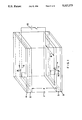
- FIG. 1 is a diagrammatic perspective view of a small portion of a liquid cell according to a preferred embodiment of the invention
- FIG. 2 shows the texture of the cell in a preferred embodiment of the invention
- FIG. 3 shows the texture of a prior-art DHF cell
- FIG. 4 shows part of a pulse sequence for actuating the cell in FIG. 1,
- FIG. 5 shows the transmittance of a 1.8 ⁇ thick cell, in the case of the pulse sequence shown in FIG. 4.
- the liquid crystal cell comprises a liquid crystal layer 1 disposed between two substantially plane- parallel plates 2, 3 made of glass or another transparent material such as acrylic glass or plastics sheets.
- the spacing between the plates is obtained in known manner, using polymer balls having a diameter of 2 ⁇ .
- a polarizer 4 is disposed in front of the front plate 2 and connected thereto preferably by sticking.
- a polarizer 5 is similarly associated with the rear plate 3.
- the surfaces of plates 2, 3 facing the liquid crystal have the conventional electrode coatings, which are segmented to represent characters or image spots.
- the portion of a cell shown in FIG. 1 has only a single electrode segment 6 on plate 2 and a facing electrode segment 7 on the rear plate 3.
- the surfaces of the glass plates facing the liquid crystal i.e. the inner surfaces, are also treated so that they exert a directional effect on the adjacent liquid-crystal molecules and thus determine the direction of the director.
- the result of this treatment is called "surface orientation”.
- One known method of surface orientation is to provide the inner surfaces of the glass plates with a PVA layer which is rubbed in one direction.
- the directions in which the two plates are rubbed are approximately parallel.
- Another possible method of obtaining optimum parallelism of the dislocation lines is to rub only one of the two plates.
- Another known method of surface orientation is oblique vacuum metallizing of orienting layers, etc.
- the polarizer 4 belonging to the front plate is disposed at an angle ⁇ to the axis of the helix or the direction of the dislocation lines.
- the polarizer belonging to the rear plate is rotated through an angle of 90° relative to the front polarizer.
- The-directions of polarization are shown by the long arrows in FIG. 1.
- This arrangement of polarizers is a preferred embodiment. Other arrangements are possible and likewise give good results.
- the suitable polarizer arrangements can be determined without difficulty, by simple adjustment.
- the liquid crystal 1 is a chiral smectic ferroelectric crystal, frequently described as smectic C (S C ) in the literature.
- Liquid crystals of this kind are known from the literature. They are characterized by the fact that the molecules are disposed not at right angles to the smectic planes but at a certain angle, the smectic tilt angle ⁇ o .
- the chirality is due to the fact that, unless influenced by walls or electric fields, the directions of the molecules are not parallel in all the layers, but are in different directions in different layers, resulting in an overall helical twist.
- the liquid crystal is preferably a mixture of an achiral S C host mixture comprising at least two LC components, at least one containing a tilted smectic phase (e.g. S C ), and one or more chiral dopants which individually or together induce a helical pitch p ⁇ 1 ⁇ m, the spontaneous polarizability of the total mixture being P>10 nC/cm 2 and the S c tilt angle of the final mixture being ⁇ >10°.
- the following values are particularly preferred: P>20 nC/cm 2 and ⁇ >17°.
- Such substances are described in U.S. Pat. applications Ser. Nos. 07/464,610 and 07/455,470 (applications corresponding to EP-A-0 269 963 which corresponds to U.S. Pat. No. 5,100,577) and include compounds of formula ##STR1## wherein R 11 and R 12 each independently represent optionally halogen-substituted C 1 -C 18 -alkyl or optionally halogen-substituted C 2 -C 18 -alkenyl in which optionally one CH 2 group or two non-adjacent CH 2 groups are replaced by oxygen; rings B, C and D denote 1,4-phenylene optionally substituted with cyano, halogen or lower alkyl; n stands for the number 0 or 1; E is a single covalent bond; and Y 1 and Y 2 are hydrogen or one of Y 1 and Y 2 is also cyano.
- 07/343,477 including compounds of formula ##STR8## wherein rings A, B and C each independently are 1,4-phenylene, which is unsubstituted of substituted with at least one of halogen, cyano, methyl or methoxy, and in which optionally 1 CH group or 2 CH groups is/are replaced by nitrogen:
- R 1 represents the radical of an optically active terpene alcohol after cleavage of the hydroxy group or a group --(CH 2 ) m --C*HX 1 --R 3
- R 2 represents the radical of an optically active terpene alcohol after cleavage of the hydroxy group or a group --(CH 2 ) n --C*HX 2 --R 4 ;
- m and n each independently stand for the number 0 or 1;
- C* denotes a chiral carbon atom;
- X 1 and X 2 each independently represent fluorine, chlorine, cyano, methyl or methoxy;
- R 3 and R 4 each independently de
- Preferred chiral dopants include optically active compounds having formula: ##STR9## wherein n stands for the number 0 or 1: the rings A, B and C independently denote 1,4-phenylene, unsubstituted or substituted by halogen, cyano, methyl and/or methoxy and in which 1 or 2 CH groups are replaced by nitrogen if required, or one of the rings A, B and C also denotes trans-1,4-cyclohexylene; Z 1 and Z 2 independently denote a single covalent bond, --CH 2 CH 2 , --OCH 2 --, --CH 2 O--, --COO-- or --OOC--; Z 3 and Z 4 independently denote a single covalent bond or oxygen, --COO-- or --OOC; R 1 and R 2 independently denote the radical of an optically active terpene alcohol after splitting off the hydroxy group or a chiral group --C*HX 1 --R 3 , --CH 2 C*HX 1 --R 3 , --C*
- R 1 is alkyl or perfluoroalkyl with 1-12 carbon atoms or an alkyl or perfluoroalkyl group with 1-12 carbon atoms in which one or two non-adjacent CH 2 or CF 2 groups are replaced by at least one of --O--, --CO--, --COO--, --CH ⁇ CH--, --CHhalogen--, --CHCN--, --O--CO--CHhalogen-- or --O--CO--CHCN--;
- R 5 is different from Y' and signifies alkyl with 1-15 carbon atoms or an alkyl group with 1-15 carbon atoms in which one or two non-adjacent CH 2 groups are replaced by at least one of --O--, --CO--, --O--CO--, --CO--O-- or --CH ⁇ CH--;
- a 2 , A 3 and A 4 each independently are unsubstituted 1,4-phenylene or 1,4-phenylene substituted with
- Z 1 and Z 2 preferably each denote a single covalent bond.
- all the rings A 2 , A 3 , A 4 , A, B and C are aromatic, more particularly 1,4-phenylene.
- Z 3 preferably stands for --OOC-- and Z 4 stands for --COO--.
- One preferred group of chiral dopants comprises those optically active compounds of formula I in which n stands for the number 1; the rings A, B and C independently denote 1,4-phenylene unsubstituted or substituted by halogen, cyano, methyl and/or methoxy, and in which 1 or 2 groups are replaced by nitrogen if required; Z 1 and Z 2 each denote a single covalent bond; Z 3 denotes --OOC-- and Z 4 denotes --COO--; R 1 and R 2 independently denote the radical of an optically active terpene alcohol after splitting off the hydroxy group of a chiral group --CH*X 1 R 3 or --CH 2 --C*HX 1 --R 3 ; C* denotes a chiral carbon atom; Z 1 denotes fluorine, chlorine, cyano, methyl or methoxy, and R 3 denotes alkyl or alkenyl.
- 1,4-phenylene, unsubstituted or substituted with halogen, cyano, methyl and/or methoxy, in which 1 or 1 CH groups are replaced by nitrogen if required comprises groups such as 1,4-phenylene, fluoro-1,4- phenylene, chloro-1,4-phenylene, cyano-1,4-phenylene, 2,3-dicyano-1,4-phenylene, methyl-1,4-phenylene, methoxy-1,4-phenylene, pyridine-2,5-diyl, pyrimidine-2,5-diyl, pyrazine- 2,5-diyl, pyridazine-3,6-diyl and the like.
- halogen comprises fluorine, chlorine, bromine and iodine, preferably fluorine and chlorine.
- radical of an optically active terpene alcohol after splitting off the hydroxy group denotes the group T of an optically active terpene alcohol having the formula TOH.
- terpene alcohol is well known to the skilled addressee, e.g. from Romps Chemie-Lexikon, Volume 6 (1977), and denotes alcohols derived from monoterpenes.
- monoterpene includes terpene hydrocarbon C 10 H 15 and hydrogenation and dehydrogenation derivatives thereof.
- optically active terpene alcohols (1R,2S,5R)-(-)-menthol, (1S,2R,5R)-(+)-isomenthol, (1S,2S,3S,5R)-(+)-isopinocampheol, (1S)-(-)-borneol, (1R)-(-)-myrtenol, (1S, 2S,5R)-(+)-neomenthol, (-)-carveol, (+)-dihydrocarveol, (+)-terpinene-4-ol, (+)- ⁇ -terpineol and the like.
- alkyl and alkenyl include straight-chain and branched radicals, preferably with not more than 15 carbon atoms, such as methyl, ethyl, propyl, isopropyl, butyl, isobutyl, pentyl, hexyl, heptyl, octyl, nonyl, vinyl, 1-propenyl, 1-butenyl, 1-pentenyl, allyl, 2-butenyl, 2-pentenyl, 3-butenyl, 3-pentenyl, 4-pentenyl, 5-hexenyl, 6-heptenyl and the like.
- the following compounds are examples of particularly preferred chiral dopants (C denotes a crystalline phase, S C * denotes a chiral smectic C phase, S A denotes a smectic A, Ch denotes a cholesteric and I denotes the isotropic phase, the spontaneous polarization P S was measured for a mixture of 5 wt. % of the dopant and 95 wt. % of 4-oxtyloxybenzoic acid-4-hexyloxyphenyl ester, and P S e is the extrapolated value of the spontaneous polarization):
- phenyl pyrimidines having the formula VII given in U.S. application Ser. Nos. 07/464,610 and 07/455,470 (EP-A-0 269 963) described above are particularly suitable compounds for the aforementioned S C materials.
- the S C hose mixture contains at least about 50 wt. % of the aforementioned compounds.
- a particularly preferred mixture consists of
- liquid crystal The exact configuration of the liquid crystal, however, is not known. It is assumed that twist and the like also occur inside the layers but are not at present measurable. Also, the liquid crystal is in a dynamic equilibrium, i.e. the structures are subject to continuous changes. For this reason, no molecular arrangement is shown in the drawings.
- the texture of the liquid crystal in the cell is characteristic and distinguishable from other textures known in the prior art.
- the texture recorded in a cell according to the invention with a 2 ⁇ thick layer without an applied voltage and between crossed polarizers is characterized by substantially parallel dislocation lines. Only one plate has a surface orientation produced by rubbing.
- the liquid crystal mixture is filled between the plates when hot, i.e. by capillary action when in the isotropic state, and is cooled to room temperature at an applied a.c. voltage of 30 V, 10 kHz.
- the symbolically-indicated voltage source 10 delivers periodic signals or actuating pulses which can have opposite polarity in the present cell, as explained in detail hereinafter.
- the director When the cell has been shaped by an electric field, i.e. the helix has been wound, the director, when no field is applied, is in one of two bistable positions. If a suitably polarized voltage is applied, it can be flipped. into the other stable position, thus altering the light-transmitting capacity of the cell.
- the optical contrast is greatest if firstly the angle is chosen so that the light-transmitting capacity is at a minimum in one stable position, and if secondly the switching angle (the angle between the projections of the director on to the plane of the electrodes in the two stable positions) is substantially equal to 45°.
- Test measurements were made on a cell having the aforementioned construction.
- a pulse sequence part of which is shown in FIG. 4, was applied to the cell. The sequence increases in linear manner from zero to 26 V. The last pair of pulses is shown. The left bipolar pulse switches the cell from light to dark whereas the right-hand pulse switches from dark to light. The width of each positive and negative pulse is 40 ⁇ sec. An important feature of this actuation is that the average value of the applied voltage is zero, preventing electrochemical decomposition of the liquid crystal.
- FIG. 5 shows the corresponding transmission curve for the top liquid-crystal mixture in a 1.8 ⁇ thick cell and with the pulse sequence shown in FIG. 4 at 25° C.
Abstract
Description
R.sup.1 --C.sup.* HX--Q--A.sup.4 --Z.sup.1 --A.sup.2 --(Z.sup.2 --A.sup.3).sub.n --X'--Q'--C.sup.* HY'--R.sup.5 II
Claims (4)
Priority Applications (1)
| Application Number | Priority Date | Filing Date | Title |
|---|---|---|---|
| US08/046,468 US5327273A (en) | 1989-06-29 | 1993-04-12 | Bistable ferroelectric liquid crystal display cell |
Applications Claiming Priority (10)
| Application Number | Priority Date | Filing Date | Title |
|---|---|---|---|
| CH240889 | 1989-06-29 | ||
| CH2408/89 | 1989-06-29 | ||
| CH244789 | 1989-06-30 | ||
| CH2447/89 | 1989-06-30 | ||
| CH3780/89 | 1989-10-18 | ||
| CH378089 | 1989-10-18 | ||
| US54350890A | 1990-06-26 | 1990-06-26 | |
| US77073991A | 1991-10-09 | 1991-10-09 | |
| US92588292A | 1992-08-06 | 1992-08-06 | |
| US08/046,468 US5327273A (en) | 1989-06-29 | 1993-04-12 | Bistable ferroelectric liquid crystal display cell |
Related Parent Applications (1)
| Application Number | Title | Priority Date | Filing Date |
|---|---|---|---|
| US92588292A Continuation | 1989-06-29 | 1992-08-06 |
Publications (1)
| Publication Number | Publication Date |
|---|---|
| US5327273A true US5327273A (en) | 1994-07-05 |
Family
ID=27543676
Family Applications (1)
| Application Number | Title | Priority Date | Filing Date |
|---|---|---|---|
| US08/046,468 Expired - Lifetime US5327273A (en) | 1989-06-29 | 1993-04-12 | Bistable ferroelectric liquid crystal display cell |
Country Status (1)
| Country | Link |
|---|---|
| US (1) | US5327273A (en) |
Cited By (11)
| Publication number | Priority date | Publication date | Assignee | Title |
|---|---|---|---|---|
| US5530569A (en) * | 1992-03-18 | 1996-06-25 | Canon Kabushiki Kaisha | Ferroelectric liquid crystal device with AC electric field pretreatment for bistability |
| US5670978A (en) * | 1993-12-28 | 1997-09-23 | Shimadzu Corporation | Light modulator using an asymetrically-driven ferroelectric liquid crystal thick cell |
| US6046789A (en) * | 1996-11-21 | 2000-04-04 | Rolic Ag | Bistable ferroelectric liquid crystal cell |
| US6703082B1 (en) | 2001-06-20 | 2004-03-09 | Displaytech, Inc. | Bookshelf liquid crystal materials and devices |
| US20040089843A1 (en) * | 2002-08-03 | 2004-05-13 | Merck Patent Gmbh | Liquid-crystalline medium and liquid-crystal display having high twist |
| US20040173775A1 (en) * | 2001-06-13 | 2004-09-09 | Juliane Suermann | Fluid crystalline medium and high-torsion liquid crystalline display device |
| US6838128B1 (en) | 2002-02-05 | 2005-01-04 | Displaytech, Inc. | High polarization dopants for ferroelectric liquid crystal compositions |
| US6870163B1 (en) | 1999-09-01 | 2005-03-22 | Displaytech, Inc. | Ferroelectric liquid crystal devices using materials with a de Vries smectic A phase |
| US7083832B2 (en) | 2000-09-01 | 2006-08-01 | Displaytech, Inc. | Partially fluorinated liquid crystal material |
| US7195719B1 (en) | 2001-01-03 | 2007-03-27 | Displaytech, Inc. | High polarization ferroelectric liquid crystal compositions |
| WO2011112121A1 (en) * | 2010-03-11 | 2011-09-15 | Закрытое Акционерное Общество "Мегавижн" | Ferroelectric liquid crystal display cell |
Citations (17)
| Publication number | Priority date | Publication date | Assignee | Title |
|---|---|---|---|---|
| JPS5979221A (en) * | 1982-10-29 | 1984-05-08 | Canon Inc | Electro-optical device |
| JPS61249019A (en) * | 1985-04-26 | 1986-11-06 | Canon Inc | Liquid crystal element |
| EP0213841A2 (en) * | 1985-08-19 | 1987-03-11 | The Secretary of State for Defence in Her Britannic Majesty's Government of the United Kingdom of Great Britain and | Secondary alcohol derivatives suitable for use in liquid crystal materials and devices |
| EP0219480A2 (en) * | 1985-10-14 | 1987-04-22 | S.A.R.L. S.T. Lagerwall | Ferroelectric liquid crystal devices |
| WO1987005017A2 (en) * | 1986-02-17 | 1987-08-27 | MERCK Patent Gesellschaft mit beschränkter Haftung | Optically active compounds |
| EP0259963A2 (en) * | 1986-08-07 | 1988-03-16 | Lloyd Elias Robilliard | Improvements relating to separating products grown in soil |
| EP0269963A2 (en) * | 1986-11-28 | 1988-06-08 | F. Hoffmann-La Roche Ag | Ferroelectric liquid crystals |
| EP0283916A2 (en) * | 1987-03-20 | 1988-09-28 | Hitachi, Ltd. | Liquid crystal light-modulating device imparted with memory effect and display unit utilizing same |
| EP0309774A2 (en) * | 1987-09-18 | 1989-04-05 | F. Hoffmann-La Roche Ag | Ferroelectric liquid-crystal cell |
| US4838663A (en) * | 1986-10-07 | 1989-06-13 | S.A.R.L. S.T. Lagerwall | Device for submicrosecond electro-optic modulation in the liquid crystal smectic-A phase using orthogonal bookshelf geometry |
| US4852978A (en) * | 1986-07-02 | 1989-08-01 | Stc Plc | Liquid crystal cell utilizing a ferroelectric liquid crystal having a natural pitch length is no longer than the longest wavelength of visible light |
| JPH01253716A (en) * | 1988-04-01 | 1989-10-11 | Matsushita Electric Ind Co Ltd | Ferroelectric liquid crystal panel |
| US4876028A (en) * | 1986-10-06 | 1989-10-24 | Hoechst Aktiengesellschaft | Chiral aryl-2,3-epoxyalkyl-ethers and the corresponding thio compounds thereof, and the use thereof as dopes in liquid-crystal phases |
| US4913838A (en) * | 1987-03-20 | 1990-04-03 | Chisso Corporation | Liquid crystal compound with a 4-(optically active alkyl)-3-cyanophenyl group |
| US4969719A (en) * | 1986-04-03 | 1990-11-13 | The Secretary Of State For Defence In Her Britannic Majesty's Governement Of The United Kingdom Of Great Britain And Northern Ireland | Smectic liquid crystal devices |
| US4997264A (en) * | 1986-04-03 | 1991-03-05 | The Secretary Of State For Defence In Her Britannic Majesty's Government Of The United Kingdom Of Great Britain And Northern Ireland | Ferroelectric liquid crystal devices having a high surface tilt |
| US5242619A (en) * | 1988-04-27 | 1993-09-07 | Hoffmann-La Roche Inc. | Liquid crystalline mixtures having a chiral tilted smectic phase |
-
1993
- 1993-04-12 US US08/046,468 patent/US5327273A/en not_active Expired - Lifetime
Patent Citations (20)
| Publication number | Priority date | Publication date | Assignee | Title |
|---|---|---|---|---|
| JPS5979221A (en) * | 1982-10-29 | 1984-05-08 | Canon Inc | Electro-optical device |
| JPS61249019A (en) * | 1985-04-26 | 1986-11-06 | Canon Inc | Liquid crystal element |
| EP0213841A2 (en) * | 1985-08-19 | 1987-03-11 | The Secretary of State for Defence in Her Britannic Majesty's Government of the United Kingdom of Great Britain and | Secondary alcohol derivatives suitable for use in liquid crystal materials and devices |
| US4753752A (en) * | 1985-08-19 | 1988-06-28 | The Secretary Of State For Defence In Her Britannic Majesty's Government Of The United Kingdom Of Great Britain And Northern Ireland | Secondary alcohol derivatives for use in liquid crystal materials and devices |
| EP0219480A2 (en) * | 1985-10-14 | 1987-04-22 | S.A.R.L. S.T. Lagerwall | Ferroelectric liquid crystal devices |
| WO1987005017A2 (en) * | 1986-02-17 | 1987-08-27 | MERCK Patent Gesellschaft mit beschränkter Haftung | Optically active compounds |
| US5064569A (en) * | 1986-02-17 | 1991-11-12 | Merck Patent Gesellschaft Mit Beschrankter Haftung | Optically active compounds |
| US4997264A (en) * | 1986-04-03 | 1991-03-05 | The Secretary Of State For Defence In Her Britannic Majesty's Government Of The United Kingdom Of Great Britain And Northern Ireland | Ferroelectric liquid crystal devices having a high surface tilt |
| US4969719A (en) * | 1986-04-03 | 1990-11-13 | The Secretary Of State For Defence In Her Britannic Majesty's Governement Of The United Kingdom Of Great Britain And Northern Ireland | Smectic liquid crystal devices |
| US4852978A (en) * | 1986-07-02 | 1989-08-01 | Stc Plc | Liquid crystal cell utilizing a ferroelectric liquid crystal having a natural pitch length is no longer than the longest wavelength of visible light |
| EP0259963A2 (en) * | 1986-08-07 | 1988-03-16 | Lloyd Elias Robilliard | Improvements relating to separating products grown in soil |
| US4876028A (en) * | 1986-10-06 | 1989-10-24 | Hoechst Aktiengesellschaft | Chiral aryl-2,3-epoxyalkyl-ethers and the corresponding thio compounds thereof, and the use thereof as dopes in liquid-crystal phases |
| US4838663A (en) * | 1986-10-07 | 1989-06-13 | S.A.R.L. S.T. Lagerwall | Device for submicrosecond electro-optic modulation in the liquid crystal smectic-A phase using orthogonal bookshelf geometry |
| EP0269963A2 (en) * | 1986-11-28 | 1988-06-08 | F. Hoffmann-La Roche Ag | Ferroelectric liquid crystals |
| US5100577A (en) * | 1986-11-28 | 1992-03-31 | Hoffman-La Roche Inc. | Ferroelectric liquid crystal mixtures and compounds as well as electro-optical devices employing same |
| US4913838A (en) * | 1987-03-20 | 1990-04-03 | Chisso Corporation | Liquid crystal compound with a 4-(optically active alkyl)-3-cyanophenyl group |
| EP0283916A2 (en) * | 1987-03-20 | 1988-09-28 | Hitachi, Ltd. | Liquid crystal light-modulating device imparted with memory effect and display unit utilizing same |
| EP0309774A2 (en) * | 1987-09-18 | 1989-04-05 | F. Hoffmann-La Roche Ag | Ferroelectric liquid-crystal cell |
| JPH01253716A (en) * | 1988-04-01 | 1989-10-11 | Matsushita Electric Ind Co Ltd | Ferroelectric liquid crystal panel |
| US5242619A (en) * | 1988-04-27 | 1993-09-07 | Hoffmann-La Roche Inc. | Liquid crystalline mixtures having a chiral tilted smectic phase |
Non-Patent Citations (14)
| Title |
|---|
| Acta Cryst 4: p. 219 (Jul. 7, 1950), Vries, "Rotatory Power . . . Crystal". |
| Acta Cryst 4: p. 219 (Jul. 7, 1950), Vries, Rotatory Power . . . Crystal . * |
| Beresnev et al., Soviet Technical Physics Letters 14: pp. 116 17 (Feb. 1988), Electrooptic Response . . . Polarization . * |
| Beresnev et al., Soviet Technical Physics Letters 14: pp. 116-17 (Feb. 1988), "Electrooptic Response . . . Polarization". |
| Ferroelectrics, 77: pp. 137 144 (1988), Taniguchi et al., Dependence . . . . * |
| Ferroelectrics, 77: pp. 137-144 (1988), Taniguchi et al., "Dependence . . . ". |
| Lagerwall et al., "Ferroelectric Liquid Crystals", 1984, Mol. Cryst. Liq. Cryst. vol. 114, pp. 151-187. |
| Lagerwall et al., Ferroelectric Liquid Crystals , 1984, Mol. Cryst. Liq. Cryst. vol. 114, pp. 151 187. * |
| Molecular Crystal Liquid Crystal, vol. 94, pp. 213 234, (1983), Clark et al., Ferroelectric Liquid Crystal Electro Optics Using the Surface . . . . * |
| Molecular Crystal Liquid Crystal, vol. 94, pp. 213-234, (1983), Clark et al., "Ferroelectric Liquid Crystal Electro-Optics Using the Surface . . . ". |
| Ostrovski et al., Advances in Liquid Crystal Research and Application, 1980, pp. 469 482, Behavior of Ferroelectric . . . . * |
| Ostrovski et al., Advances in Liquid Crystal Research and Application, 1980, pp. 469-482, "Behavior of Ferroelectric . . . ". |
| SID Proceedings, Society for Information Display, May 1990, pp. 106 109, J. Funfschilling and M. Schadt, Short Pitch Bistable Ferroelectric LCDs . * |
| SID Proceedings, Society for Information Display, May 1990, pp. 106-109, J. Funfschilling and M. Schadt, "Short Pitch Bistable Ferroelectric LCDs". |
Cited By (12)
| Publication number | Priority date | Publication date | Assignee | Title |
|---|---|---|---|---|
| US5530569A (en) * | 1992-03-18 | 1996-06-25 | Canon Kabushiki Kaisha | Ferroelectric liquid crystal device with AC electric field pretreatment for bistability |
| US5670978A (en) * | 1993-12-28 | 1997-09-23 | Shimadzu Corporation | Light modulator using an asymetrically-driven ferroelectric liquid crystal thick cell |
| US6046789A (en) * | 1996-11-21 | 2000-04-04 | Rolic Ag | Bistable ferroelectric liquid crystal cell |
| US6870163B1 (en) | 1999-09-01 | 2005-03-22 | Displaytech, Inc. | Ferroelectric liquid crystal devices using materials with a de Vries smectic A phase |
| US7083832B2 (en) | 2000-09-01 | 2006-08-01 | Displaytech, Inc. | Partially fluorinated liquid crystal material |
| US7195719B1 (en) | 2001-01-03 | 2007-03-27 | Displaytech, Inc. | High polarization ferroelectric liquid crystal compositions |
| US20040173775A1 (en) * | 2001-06-13 | 2004-09-09 | Juliane Suermann | Fluid crystalline medium and high-torsion liquid crystalline display device |
| US6703082B1 (en) | 2001-06-20 | 2004-03-09 | Displaytech, Inc. | Bookshelf liquid crystal materials and devices |
| US6838128B1 (en) | 2002-02-05 | 2005-01-04 | Displaytech, Inc. | High polarization dopants for ferroelectric liquid crystal compositions |
| US20040089843A1 (en) * | 2002-08-03 | 2004-05-13 | Merck Patent Gmbh | Liquid-crystalline medium and liquid-crystal display having high twist |
| US6858268B2 (en) * | 2002-08-03 | 2005-02-22 | Merck Patent Gmbh | Liquid-crystalline medium and liquid-crystal display having high twist |
| WO2011112121A1 (en) * | 2010-03-11 | 2011-09-15 | Закрытое Акционерное Общество "Мегавижн" | Ferroelectric liquid crystal display cell |
Similar Documents
| Publication | Publication Date | Title |
|---|---|---|
| US6482479B1 (en) | Active matrix displays having high contrast values | |
| Kelly et al. | Liquid crystals for electro-optic applications | |
| US5327273A (en) | Bistable ferroelectric liquid crystal display cell | |
| US6171519B1 (en) | Ferroelectric liquid crystal mixture | |
| JP2004507607A (en) | Liquid crystal mixture | |
| US5316694A (en) | Antiferroelectric liquid crystal composition | |
| US4892676A (en) | Phenyl pyrimidine compound and liquid crystalline composition | |
| KR0171891B1 (en) | Liquid crystal display cell with chiral ferroelectric smectic liquid crystal layer | |
| US5021191A (en) | Optically active-2-alkoxy-propyl ether and liquid crystal composition | |
| NO177539B (en) | Ferroelectric liquid crystal composition and light switching element | |
| US5779935A (en) | Ferroelectric liquid crystal mixture | |
| EP0391986B1 (en) | Display element based on the electroclinic effect | |
| JPH06306363A (en) | Smectic liquid crystal mixture | |
| JPH06330042A (en) | Smectic liquid crystal mixture | |
| EP0306195B1 (en) | Optically active-2,5-diphenylpyridines | |
| JPH0762349A (en) | Smectic liquid crystal mixture | |
| EP0411122A1 (en) | Ferroelectric liquid crystal composition | |
| EP0345091A2 (en) | Ferroelectric liquid crystal compositions | |
| US5676880A (en) | Ferroelectric liquid crystal cell | |
| US5807499A (en) | Liquid crystal composition and a liquid crystal display device containing the same | |
| EP0347941B1 (en) | Chiral smectic liquid crystal composition and liquid crystal device using same | |
| JP3826416B2 (en) | Liquid crystal composition and liquid crystal display element | |
| US6551668B1 (en) | Monostable ferroelectric active matrix display | |
| EP0352480A2 (en) | Ferroelectric chiral smectic liquid crystal composition and liquid crystal device using same | |
| JPS63104949A (en) | Fluoroalkane derivative, liquid crystal composition and liquid crystal element containing said derivative |
Legal Events
| Date | Code | Title | Description |
|---|---|---|---|
| STPP | Information on status: patent application and granting procedure in general |
Free format text: APPLICATION UNDERGOING PREEXAM PROCESSING |
|
| AS | Assignment |
Owner name: ROLIC LTD., SWITZERLAND Free format text: ASSIGNMENT OF ASSIGNORS INTEREST;ASSIGNOR:HOFFMANN-LA ROCHE INC.;REEL/FRAME:008334/0298 Effective date: 19970127 |
|
| FEPP | Fee payment procedure |
Free format text: PAYOR NUMBER ASSIGNED (ORIGINAL EVENT CODE: ASPN); ENTITY STATUS OF PATENT OWNER: LARGE ENTITY |
|
| FPAY | Fee payment |
Year of fee payment: 4 |
|
| AS | Assignment |
Owner name: STATE SCIENTIFIC CENTER OF THE RUSSIAN FEDERATION Free format text: CHANGE OF NAME;ASSIGNOR:MOSCOW RESEARCH AND PRODUCTION (SIC "INDUSTRIAL") ASSOCIATION "NIOPIK";REEL/FRAME:009064/0158 Effective date: 19970401 |
|
| AS | Assignment |
Owner name: ROLIC LTD., SWITZERLAND Free format text: AGREEMENT;ASSIGNORS:F. HOFFMANN-LA ROCHE LTD.;STATE SCIENTIFIC CENTRE OF THE RUSSIAN FEDERATION "NIOPIK", THE;REEL/FRAME:009289/0896 Effective date: 19961220 Owner name: F.HOFFMAN-LA ROCHE LTD., SWITZERLAND Free format text: AGREEMENT-PROTECTION AND USE OF JOINT INVENTIONS;ASSIGNOR:ORGANIC INTERMEDIATES AND DYES INSTITUTE;REEL/FRAME:009396/0675 Effective date: 19891201 |
|
| AS | Assignment |
Owner name: STATE SCIENTIFIC CENTER OF THE RUSSIAN FEDERATION Free format text: CHANGE OF NAME;ASSIGNOR:ORGANIC INTERMEDIATES AND DYES INSTITUTE;REEL/FRAME:009103/0330 Effective date: 19980316 |
|
| AS | Assignment |
Owner name: STATE SCIENTIFIC CENTER OF THE RUSSIAN FEDERATION Free format text: CERTIFICATE TO ENGAGE IN ECONOMIC ACTIVITY;ASSIGNOR:COMMITTEE OF THE RUSSIAN FEDERATION FOR CHEMICAL AND PETROCHEMICAL INDUSTRY;REEL/FRAME:009328/0501 Effective date: 19931223 |
|
| AS | Assignment |
Owner name: STATE SCIENTIFIC CENTER OFTHE RUSSIAN FEFERATION " Free format text: CERTIFICATE OF REGISTRATION;ASSIGNOR:MOSCOW REGISTRATION CHAMBER;REEL/FRAME:009350/0132 Effective date: 19931223 |
|
| FEPP | Fee payment procedure |
Free format text: PAYER NUMBER DE-ASSIGNED (ORIGINAL EVENT CODE: RMPN); ENTITY STATUS OF PATENT OWNER: LARGE ENTITY Free format text: PAYOR NUMBER ASSIGNED (ORIGINAL EVENT CODE: ASPN); ENTITY STATUS OF PATENT OWNER: LARGE ENTITY |
|
| FPAY | Fee payment |
Year of fee payment: 8 |
|
| FPAY | Fee payment |
Year of fee payment: 12 |