US5325632A - Composite door assembly - Google Patents
Composite door assembly Download PDFInfo
- Publication number
- US5325632A US5325632A US07/964,376 US96437692A US5325632A US 5325632 A US5325632 A US 5325632A US 96437692 A US96437692 A US 96437692A US 5325632 A US5325632 A US 5325632A
- Authority
- US
- United States
- Prior art keywords
- door
- panel
- inner panel
- belt
- outer panels
- Prior art date
- Legal status (The legal status is an assumption and is not a legal conclusion. Google has not performed a legal analysis and makes no representation as to the accuracy of the status listed.)
- Expired - Lifetime
Links
Images


Classifications
-
- B—PERFORMING OPERATIONS; TRANSPORTING
- B60—VEHICLES IN GENERAL
- B60J—WINDOWS, WINDSCREENS, NON-FIXED ROOFS, DOORS, OR SIMILAR DEVICES FOR VEHICLES; REMOVABLE EXTERNAL PROTECTIVE COVERINGS SPECIALLY ADAPTED FOR VEHICLES
- B60J5/00—Doors
- B60J5/04—Doors arranged at the vehicle sides
- B60J5/042—Reinforcement elements
- B60J5/0422—Elongated type elements, e.g. beams, cables, belts or wires
- B60J5/0423—Elongated type elements, e.g. beams, cables, belts or wires characterised by position in the lower door structure
- B60J5/0426—Elongated type elements, e.g. beams, cables, belts or wires characterised by position in the lower door structure the elements being arranged at the beltline
-
- B—PERFORMING OPERATIONS; TRANSPORTING
- B60—VEHICLES IN GENERAL
- B60J—WINDOWS, WINDSCREENS, NON-FIXED ROOFS, DOORS, OR SIMILAR DEVICES FOR VEHICLES; REMOVABLE EXTERNAL PROTECTIVE COVERINGS SPECIALLY ADAPTED FOR VEHICLES
- B60J5/00—Doors
- B60J5/04—Doors arranged at the vehicle sides
- B60J5/042—Reinforcement elements
- B60J5/0422—Elongated type elements, e.g. beams, cables, belts or wires
- B60J5/0423—Elongated type elements, e.g. beams, cables, belts or wires characterised by position in the lower door structure
- B60J5/0425—Elongated type elements, e.g. beams, cables, belts or wires characterised by position in the lower door structure the elements being arranged essentially horizontal in the centre of the lower door structure
Definitions
- This invention relates to a composite vehicle door structure and, more particularly, to a composite vehicle door structure including a tailored steel inner panel and a plastic outer panel wherein the panels are separated by a belt-line reinforcing member.
- the conventional door assembly usually includes a relatively thin inner panel formed by metal stamping, an outer panel of metal which is hemmed around the marginal edges of the inner panel and an intrusion beam extending longitudinally across the inner panels as major components. Often, it is necessary to further reinforce the inner panel along the side edges and proximate to the hinges because of the weight of the door assembly and the operational loads to which the door is subjected.
- the present invention is directed to solving one or more of these problems.
- the present invention is primarily concerned with greatly reducing the total number of parts necessary to make vehicle doors which are structurally sound, attractive, and easy to manufacture.
- the composite vehicle door assembly has substantially fewer parts than conventional vehicle door assemblies.
- the composite vehicle door structure includes a tailored steel inner panel, a composite or plastic outer body panel, as well as a belt-line reinforcement member which separates the inner and outer door panels along the bottom edge of the window opening and an intrusion beam.
- the tailored inner panel and plastic outer panel can be adhered together in various ways under the present invention.
- the belt-line reinforcing member is disposed between the inner and outer door panels to enhance the shock absorbing characteristics of the vehicle door during a collision.
- the reinforcing member also provides for proper spacing between the inner and outer door panels.
- One of the advantages of the present invention is a decrease in the unit cost of the vehicle door. By reducing the number of parts which make up the vehicle door structure and the assembly of parts, the amount expended for producing the vehicle door structure, as well as labor costs, will be reduced.
- Another advantage of the present invention is a reduction inventories and inventory costs.
- Yet another advantage of the present invention is a reduction in the weight of the vehicle door structure. This translates into better fuel efficiency which, in turn, means cost savings to the consumer.
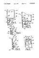
- FIG. 1 is an exploded perspective view of the door structure made in accordance with the teaching of the present invention
- FIG. 1a is a top view of the belt-line reinforcement of FIG. 1.
- FIG. 2 is a simplified cross-sectional view taken along lines 2--2 of FIG. 1 which illustrates the intrusion beam and tailoring of the inner door panel according to the present invention
- FIG. 3 is a simplified cross-sectional view which illustrates a first method of bonding the plastic outer panel to the steel inner panel according to the teaching of the present invention
- FIG. 4 is a simplified cross-sectional view which illustrates a second method of bonding the plastic outer panel to the steel inner panel according to the teachings of the present invention
- FIG. 5 is a simplified cross-sectional view which illustrates a third method of bonding the plastic outer panel to the steel inner panel according to the teachings of the present invention
- FIG. 6 is a simplified cross-sectional view which illustrates a fourth method of bonding the plastic outer panel to the steel inner panel according to the teaching of the present invention
- FIG. 7a is a simplified cross-sectional view which illustrates a fifth method of bonding the plastic outer panel to the steel inner panel according to the teachings of the present invention
- FIG. 7b is an enlarged sectional view further illustrating the method according to FIG. 7a;
- FIG. 8 is a simplified cross-sectional view illustrating a method of attaching the belt-line reinforcement member between the inner and outer door panels.
- FIG. 9 is a schematic diagram illustrating a method of manufacturing the composite vehicle door assembly of the present invention.
- the methods and apparatus of the present invention are concerned with providing a vehicle door assembly 10 having a tailored steel inner panel 12, a plastic outer panel 14, a belt-line reinforcing member 16 which separates the inner and outer panels along the lower edge of the window frame and an intrusion beam 18.
- Much of the focus of this invention is directed to the tailored steel inner panel 12.
- the inner panel 12, which is formed by stamping galvanized sheet metal to define a shape corresponding to that of the door opening in the vehicle with which it will be used, has a body including a lower generally rectangular portion 20 and a upper generally trapozidal portion 22. The intersection of the upper and lower portions is commonly referred to as the belt-line 24.
- additional steel reinforcement is provided along the laterally extending leading end 38 to increase the structural rigidity of the inner door panel 12.
- This additional steel reinforcement is accomplished generally by tailoring the inner door panel. Tailoring occurs by providing two or more separate inner door panel sections then aligning and joining them to form a single inner door panel. The sections may be combined in any suitable manner, but preferably are joined by laser welding. As demonstrated in FIG. 1, the laser weld would occur along the fissure 44 where the first and second door panel sections 46 and 48, respectively, are combined. It should be noted however that the tailoring may occur at various points along the inner panel and in one embodiment (not shown) the tailoring occurs along the lateral portion where the additional steel reinforcement and the thinner portion inner panel section converge.
- the inner panel is typically provided with a plurality of openings for access to the internal mechanisms such as window regulators and door latches (not shown) which are disposed within the vehicle door between the inner and outer panels.
- the trapezoidal portion includes the window frame 26 and a window opening 28.
- the periphery of the inner panel 12 is provided with an edge portion 30 which provides an area for attachment to the outer panel 14.
- a pair of detents 36 may be provided along the leading and trailing edges 32 and 34, respectively, for hosting the inwardly projecting trim strip track 50 of the outer panel 14.
- the outer door panel 14 which preferably is formed of a sheet molded compound (SMC) is provided for attachment to the inner panel.
- the outer door panel 14 includes an outer surface 52 which is exposed to the environment and an inner surface 54 which mates with peripheral edge 30 of inner panel 12.
- the belt-line reinforcement member 16 Disposed between the inner and outer panels and located along the belt-line 24 is a belt-line reinforcement member 16 as shown in FIGS. 1 and 8.
- the belt-line reinforcement member is a one-piece construction made from rigid fiber-reinforced plastic or steel having an overall rectangular shape.
- the belt-line reinforcement member includes a hollow body portion 56 having a first section 58 which forms an annular shoulder extending radially outwardly from the body portion and located along the bottom edge for attachment to the inner and outer door panels 12 and 14, respectively.
- Body portion 56 also includes a second section 60 which extends between the first portion 58 and the transversely disposed top surface 62.
- the top surface 62 is provided with a slot 64 for allowing the window 66 to pass therethrough when the window 66 is in an at least partially closed position as demonstrated in FIG. 8.
- one or more spacers 65 as shown in FIG. 1a extend across the slot to maintain the opening during assembly and are thereafter removed by trimming or punching them out after the door is assembled.
- Attachment of the belt-line reinforcement member to the inner and outer panels is typically accomplished through the use of an adhesive 70 which is applied to both the inner and outer panels.
- the adhesive allows the annular shoulder 58 to be bonded to both the inner surface 42 of the inner panel 12 and the inner surface 54 of the outer panel 14.
- a second amount of adhesive 72 is used to secure the top surface 62 to the incurved portions of the inner and outer panels 70 and 72, respectively.
- the belt-line reinforcement member of FIGS. 1 and 8 is utilized to maintain spacing and improve structural rigidity between the tailored steel inner panel 12 and a composite outer panel 14, it will be understood by those skilled in the art that the belt-line reinforcement member of the present invention can be effectively utilized in door embodiments made of other materials as well.
- An intrusion beam assembly 18 is provided for reinforcing the door assembly and absorbing impact forces in the event of a collision.
- the intrusion beam 78 is formed of a relatively rigid metal and includes a first end 80 and a second end 82. In the embodiment of FIGS. 1 and 2, the first end is secured within a recess 86 located proximate to the leading edge 32 of the inner panel 12 and the second end is secured within a recess 88 located proximate to the trailing edge 34 of the inner panel 12.
- a brace 90 is attached near the second end 82 of the beam 78.
- the brace 90 includes a slot 92 which provides for a slip plain to adjust the intrusion beam when necessary and is attached to the inner door panel by a nut and bolt assembly 94.
- the brace provides additional support to the intrusion beam. Securement of the intrusion beam can also be accomplished by other suitable fastening means such as by a system known as TOG-L-LOC (a trademark of BTM Corp. of Marysville, Mich.) wherein the sheet metal is punched into conforming engagement.
- TOG-L-LOC a trademark of BTM Corp. of Marysville, Mich.
- the beam extends across the lower portion 20 of the inner door panel between the leading end 38 and the second, laterally extending trailing end 40 thereby bridging the tailored and non-tailored portions of the inner door panel 12.
- the intrusion beam assembly of the present invention is of a high strength construction and involves fewer parts than other known intrusion beam assemblies which directly results in a desirable weight reduction for the door assembly 10.
- FIGS. 3 through 7b various methods of joining the tailored steel inner panel 12 and the composite or plastic outer panel 14 according to the teachings of the present invention are illustrated. Reference numerals for the inner panel 12, inner surface 42, outer panel 14, and surface 54 are utilized for each of the FIGS. 3 through 7b.
- the tailored steel inner panel 12 is shown to include a frame 96 having contoured end 104 for attachment to outer panel.
- the frame includes a body 98, a transitional step 100 and an extending portion 102 leading to the end portion 104.
- the extending portion 102 is spaced apart from the inner surface 54 of the outer panel 14 to provide sufficient space for bracket member 106.
- a plurality of spaced apart brackets 106 are utilized to assist in securing the inner and outer panels together.
- the brackets are U-shaped in cross-section having a first leg 108 and a second leg 110.
- the first leg 108 of the bracket 106 is secured to the inner surface 54 of the outer panel 14 by an adhesive 112 and the second leg 110 is attached to the frame 88 by a bolt 114 or another suitable fastener.
- the end 104 of the frame 96 is substantially C-shaped in cross-section and includes a back 116 disposed substantially parallel to the inner surface 54 of the outer panel 14 such that an adhesive 118 may be disposed between the back 116 and the inner surface 54 of the outer panel to further secure the inner and outer panels together.
- the steel inner panel includes a frame 120 having a body portion 122, a first transitional step 124 extending in the direction of the outer panel, an outwardly extending section 126, a second transitional step 128 extending from said outwardly extending section in the direction of the outer panel and a distal portion 130 disposed substantially parallel to the inner surface of the outer panel.
- the inner panel is designed to allow for the use of a plurality of spaced apart brackets 132 to assist in securing the steel inner panel to the outer panel.
- the brackets 132 have an overall L-shape including a first leg 134 which is attached to the inner surface 54 of the outer panel 14 along a first surface 138 by an adhesive 144 and a second leg 142 which is mechanically attached to the frame 120 along the second transitional step 128.
- the first leg 134 also includes an arm 136 extending transversely from the inner surface 140 of the first leg 134. The end of the arm 136 partially overlaps the first transitional portion 124 to align the bracket 132 within the gap 146 which occurs between the frame and the outer panel.
- the second leg 142 is provided with a slot 148 which allows for adjustment of the outer panel relative to the inner panel prior to tightening the nut and bolt fastening assembly 150 which is disposed through the slot.
- a second amount of adhesive 152 is then inserted between the distal portion 130 of the frame and the inner surface 54 of the outer panel 14 to further secure the inner and outer panels together.
- FIG. 5 yet another method of attaching the tailored steel inner panel 12 to the composite or plastic outer panel 14 according to the teachings of the present invention is shown.
- a plurality of spaced apart steel strip 154 are attached to the inner surface 54 of outer panel 14 by an adhesive 156 and to the outer surface 42 of the inner panel 12 by a second amount of adhesive 158 along a first end 160 of the strip.
- An additional amount of adhesive (not shown) may also be disposed on the surface 166 of the inner panel edge 164 to further adhere the steel strip 154 to the inner panel.
- one long steel strip or a plurality of shorter steel strips may be utilized to carry out this method of attaching the tailored steel inner panel to the composite or plastic outer panel.
- FIG. 6 yet another method of adjoining the tailored steel inner panel 12 and a composite or plastic outer panel 14 according to the teachings of the present invention is shown.
- the outer panel 14 is provided with a plurality of spaced apart post members 168 located proximate to the outer panels edge 170 and extending from the inner surface 54 thereof in the direction of the steel inner panel 12 to facilitate attachment of the inner and outer door panels.
- the inner panel 12 is provided with an edge portion 172 which includes a plurality of apertures 174 for receiving the corresponding post members 168. After the inner and outer panels have been aligned such that the post members 168 and apertures 174 are in mating engagement the panels are brought together.
- the adhesive 178 which was previously disposed within the gap 176 located between the inner and outer panel edge portions is then allowed to cure to permanently secure the inner and outer panels together.
- FIGS. 7a and 7b still another method of attaching the steel inner panel 12 and a composite or plastic outer panel 14 according to the teachings of the present invention is illustrated.
- the steel inner panel 12 is provided with a frame portion 180 having a body 182, a transitional portion 184 and an edge portion 188 having a plurality of spaced apart apertures 190 extending therethrough.
- the outer door panel 14 is provided with a plurality of spaced apart thermoplastic tabs 192 adhesively bonded to the outer panel by an adhesive 198 along the edge 200 of the outer panels inner surface 54.
- the plastic tabs 192 include a head portion 194 and a nipple 196 which is sufficiently long to extend through the corresponding aperture 190.
- plastic tabs 192 are heated to a temperature sufficient to cause the nipple to melt and expand laterally to initially lock the steel inner panel and the outer panel together. This melting of plastic tabs may be referred to as "heat staking" . Typically, there is a slight gap between the plastic tab and aperture to accommodate this expansion. A second adhesive 204 is then disposed between the gap 202 provided for between the edge portions 188 and 200, respectively, of the inner and outer panels to further secure the inner and outer panels together.
- FIG. 9 illustrates a method of manufacturing the composite vehicle door assembly 10 of the present invention.
- the tailored steel inner panel 12 along with the attached intrusion beam is washed in a suitable solvent, dried and then optionally preheated prior to receiving a desirable amount of adhesive.
- the adhesive is applied to the inner surface of the steel inner panel along the belt-line and peripheral edges.
- the belt-line reinforcement member is then attached to the inner surface of the inner door panel. Once the belt-line reinforcement member has been adhesively attached to the inner surface of the tailored steel inner panel an additional amount of adhesive is applied to the inner surface of the outer panel along the belt-line.
- the inner and outer panels are then brought together to adhesively attach the inner surface of the outer panel to the belt-line reinforcement member and adjoin the inner and outer panels to form the door assembly.
- the adhesive applications are allowed to cure to secure belt-line reinforcement and the inner and outer panels together.
- the excess material extending into the openings and slots provided on the belt-line reinforcement member and the on inner panel are then trimmed away.
- the entire assembly is then washed and the inner panel is provided with a mask to prevent overspray during painting. With the mask in place a primer paint is applied to the door assembly and allowed to cure.
- the protective mask is then removed and the door assembly is fogged by dipping or spraying the door assembly in oil to prevent rusting. After fogging the assembled door is ready to be shipped.
Abstract
Description
Claims (21)
Priority Applications (3)
| Application Number | Priority Date | Filing Date | Title |
|---|---|---|---|
| US07/964,376 US5325632A (en) | 1992-10-21 | 1992-10-21 | Composite door assembly |
| CA002108635A CA2108635A1 (en) | 1992-10-21 | 1993-10-18 | Composite door assembly |
| MX9306500A MX9306500A (en) | 1992-10-21 | 1993-10-20 | COMPOSITE DOOR ASSEMBLY. |
Applications Claiming Priority (1)
| Application Number | Priority Date | Filing Date | Title |
|---|---|---|---|
| US07/964,376 US5325632A (en) | 1992-10-21 | 1992-10-21 | Composite door assembly |
Publications (1)
| Publication Number | Publication Date |
|---|---|
| US5325632A true US5325632A (en) | 1994-07-05 |
Family
ID=25508472
Family Applications (1)
| Application Number | Title | Priority Date | Filing Date |
|---|---|---|---|
| US07/964,376 Expired - Lifetime US5325632A (en) | 1992-10-21 | 1992-10-21 | Composite door assembly |
Country Status (3)
| Country | Link |
|---|---|
| US (1) | US5325632A (en) |
| CA (1) | CA2108635A1 (en) |
| MX (1) | MX9306500A (en) |
Cited By (35)
| Publication number | Priority date | Publication date | Assignee | Title |
|---|---|---|---|---|
| US5536060A (en) * | 1995-02-17 | 1996-07-16 | General Motors Corporation | Reinforced vehicle door |
| US5573297A (en) * | 1993-11-22 | 1996-11-12 | Chrysler Corporation | Vehicle door assembly |
| US5740993A (en) * | 1994-04-15 | 1998-04-21 | Steyr-Daimler-Puch Ag | Vehicle door with separable collision protector |
| US5787646A (en) * | 1994-12-02 | 1998-08-04 | Mitsubishi Jidosha Kogyo Kabushiki Kaisha | Door panel construction and method of manufacturing door panel |
| US5813719A (en) * | 1997-09-25 | 1998-09-29 | Trim Trends, Inc. | Side intrusion beam assembly having compensating welds at brackets |
| US5857732A (en) * | 1996-02-21 | 1999-01-12 | The Budd Company | Plastic modular door for a vehicle |
| US5867942A (en) * | 1996-10-15 | 1999-02-09 | Trim Trends, Inc. | Removable door cassette for a vehicle and method of assembly |
| US5904002A (en) * | 1996-05-31 | 1999-05-18 | Lear Corporation | Motor vehicle door module |
| US5927021A (en) * | 1996-10-15 | 1999-07-27 | Trim Trends, Inc. | Door cassette for a vehicle |
| US5964063A (en) * | 1996-07-22 | 1999-10-12 | Honda Giken Kogyo Kabushiki Kaisha | Motor-vehicle door having window winder, method of assembling the door, and window sash assembly suitable for use in the door |
| US6022066A (en) * | 1998-10-15 | 2000-02-08 | Ricon Corporation | Door extension for vehicle doors |
| US6134840A (en) * | 1998-01-23 | 2000-10-24 | Brose Fahrzeugteile Gmbh & Co. Kg | Vehicle door assembly having a window lifter with movably mounted guide rails |
| US6390534B1 (en) * | 2000-11-08 | 2002-05-21 | Korea Advanced Institute Of Science And Technology | Impact beam for car doors |
| US6513860B1 (en) | 2000-04-26 | 2003-02-04 | Ford Global Technologies, Inc. | Method and apparatus for forming a three piece tailor welded door blank |
| US6536832B1 (en) * | 1999-09-28 | 2003-03-25 | Arvin Meritor Gmbh | Vehicle door including structural element support for a functional component |
| US6749254B1 (en) * | 2003-06-09 | 2004-06-15 | Ford Global Technologies, Llc | Body panel assembly |
| US20040216386A1 (en) * | 2003-04-29 | 2004-11-04 | Chernoff Adrian B. | Vehicle door having unitary inner panel and outer panel |
| US20060066446A1 (en) * | 2004-09-27 | 2006-03-30 | Mazda Motor Corporation | Automobile door structure |
| US20060267311A1 (en) * | 2003-01-29 | 2006-11-30 | Albert Brandstatter | Interior trimming piece |
| US20080007087A1 (en) * | 2006-06-09 | 2008-01-10 | Toyota Jidosha Kabushiki Kaisha | Vehicle door structure |
| US20080238136A1 (en) * | 2004-07-15 | 2008-10-02 | Daimlerchrysler Ag | Motor Vehicle Door |
| US20080251667A1 (en) * | 2007-04-16 | 2008-10-16 | Honda Motor Co., Ltd. | System for attaching components to a vehicle |
| US20090152893A1 (en) * | 2007-12-14 | 2009-06-18 | Hyundai Motor Company | Reinforcement structure for upper portion of vehicle door |
| US20090200832A1 (en) * | 2006-10-02 | 2009-08-13 | Johnson Control Technology Company | Multi-part equipment piece for a vehicle and connecting method |
| US20110254311A1 (en) * | 2010-04-15 | 2011-10-20 | Lanxess Deutschland Gmbh | Door structure module |
| DE10061642B4 (en) * | 2000-12-11 | 2012-01-12 | Volkswagen Ag | Door or lid-like vehicle construction element |
| US20120091747A1 (en) * | 2010-10-15 | 2012-04-19 | Norco Industries, Inc. | Roof bow |
| US20120153670A1 (en) * | 2010-12-16 | 2012-06-21 | Magna International Inc. | Composite lift gate deformable section |
| US20150003902A1 (en) * | 2013-06-28 | 2015-01-01 | GM Global Technology Operations LLC | Tipped surfaces for mixed material joining and methods of making and using the same |
| US9308577B2 (en) | 2011-09-30 | 2016-04-12 | ArcelorMittal Investigacion y Desarrolli, S.L. | Lightweight steel door for vehicle and method for manufacturing the same |
| EP3243579A1 (en) * | 2016-05-12 | 2017-11-15 | 3M Innovative Properties Company | Method of bonding panels to a panel assembly and panel assembly |
| US20190039442A1 (en) * | 2016-12-30 | 2019-02-07 | Advanced Comfort Systems France Sas - Acs France | Motor vehicle door, structural unit, glazed unit, corresponding manufacturing method and vehicle |
| US10864806B2 (en) * | 2019-01-24 | 2020-12-15 | Hyundai Motor Company | Door for vehicle |
| US11065945B2 (en) * | 2019-06-05 | 2021-07-20 | Nissan North America, Inc. | Vehicle door structure |
| US11235645B2 (en) * | 2017-11-01 | 2022-02-01 | Jfe Steel Corporation | Stiffening structure and stiffening method for automotive door panel part |
Citations (35)
| Publication number | Priority date | Publication date | Assignee | Title |
|---|---|---|---|---|
| US2198069A (en) * | 1938-01-24 | 1940-04-23 | Murray Corp | Method of making sheet metal vehicle doors |
| US2807498A (en) * | 1955-11-07 | 1957-09-24 | United Ind Corp | Automobile door structure |
| US3782036A (en) * | 1971-08-21 | 1974-01-01 | Gkn Sankey Ltd | Doors for vehicles |
| US3791693A (en) * | 1971-06-04 | 1974-02-12 | Ford Motor Co | Vehicle door, in particular for motor vehicles |
| US3861339A (en) * | 1973-01-31 | 1975-01-21 | Nissan Motor | Method of joining the edge portions of two sheets |
| US3862490A (en) * | 1973-01-31 | 1975-01-28 | Nissan Motor | Method of joining the edge portions of two sheets |
| US3909919A (en) * | 1973-01-31 | 1975-10-07 | Nissan Motor | Method of joining the edge portions of two sheets |
| US3909918A (en) * | 1973-01-31 | 1975-10-07 | Nissan Motor | Method of joining the edge portions of two sheets |
| US3936090A (en) * | 1973-02-28 | 1976-02-03 | Nissan Motor Co., Ltd. | Vehicle door |
| US4056280A (en) * | 1974-04-09 | 1977-11-01 | Volkswagenwerk Aktiengesellschaft | Door for vehicles, in particular motor vehicles |
| US4196929A (en) * | 1977-08-31 | 1980-04-08 | Volkswagenwerk Aktiengesellschaft | Door for a vehicle |
| EP0057270A1 (en) * | 1981-01-24 | 1982-08-11 | Messerschmitt-Bölkow-Blohm Gesellschaft mit beschränkter Haftung | Door, particularly for a motor vehicle |
| JPS57151427A (en) * | 1981-03-16 | 1982-09-18 | Nissan Motor Co Ltd | Reinforcement structure for door |
| US4411466A (en) * | 1979-12-10 | 1983-10-25 | Nissan Motor Company, Limited | Automobile door structure |
| US4411103A (en) * | 1980-05-29 | 1983-10-25 | Toyota Jidosha Kogyo Kabushiki Kaisha | Construction of a door beam of a motor vehicle |
| US4434580A (en) * | 1981-01-24 | 1984-03-06 | Messerschmitt-Boelkow-Blohm Gesellschaft Mit Beschraenkter Haftung | Door, especially for motor vehicles |
| EP0128621A2 (en) * | 1983-06-10 | 1984-12-19 | RENAULT ITALIA S.p.A. | Box-shaped vehicle door and method for its manufacture |
| US4529244A (en) * | 1982-11-19 | 1985-07-16 | General Motors Corporation | Plastic vehicle body panel mounting structure |
| US4561211A (en) * | 1983-08-05 | 1985-12-31 | General Motors Corporation | Vehicle door and window assembly |
| US4597153A (en) * | 1982-11-19 | 1986-07-01 | General Motors Corporation | Method for mounting plastic body panel |
| US4648208A (en) * | 1982-03-12 | 1987-03-10 | Brose Fahreugteile Gmbh & Co. Kommanditgesellschaft | Door unit for motor vehicles |
| US4651470A (en) * | 1985-06-25 | 1987-03-24 | Mazda Motor Corporation | Vehicle door structure having plastic door panel |
| US4662115A (en) * | 1985-01-21 | 1987-05-05 | Mazda Motor Corporation | Vehicle door |
| NL8600543A (en) * | 1986-03-04 | 1987-10-01 | Volvo Car Bv | VEHICLE WITH A CABIN COVER WITH INTERNAL REINFORCEMENT ELEMENTS. |
| US4711052A (en) * | 1985-12-05 | 1987-12-08 | Mazda Motor Corporation | Vehicle door structure |
| US4731951A (en) * | 1983-12-26 | 1988-03-22 | Toyota Jidosha Kabushiki Kaisha | Vehicle door structure |
| US4831710A (en) * | 1986-08-25 | 1989-05-23 | Mazda Motor Corporation | Method of assembling a vehicle door |
| US4843762A (en) * | 1987-04-14 | 1989-07-04 | The Budd Company | Vehicle door with split outer panel |
| US4861407A (en) * | 1985-06-18 | 1989-08-29 | The Dow Chemical Company | Method for adhesive bonding articles via pretreatment with energy beams |
| US4945682A (en) * | 1989-12-04 | 1990-08-07 | General Motors Corporation | Plastic motor vehicle door |
| US4968383A (en) * | 1985-06-18 | 1990-11-06 | The Dow Chemical Company | Method for molding over a preform |
| US5033236A (en) * | 1989-06-29 | 1991-07-23 | Brose Fahrzeugteile Gmbh & Co. Kg | Motor vehicle door |
| US5083832A (en) * | 1989-07-12 | 1992-01-28 | Mazda Motor Corporation | Structure of vehicle door |
| US5090158A (en) * | 1989-03-03 | 1992-02-25 | Rockwell International Corporation | Support for preassembled and preadjusted fittings for a motor vehicle door, and a door having this support |
| US5095659A (en) * | 1989-05-02 | 1992-03-17 | Atoma International, A Magna International Company | Automobile door modular assembly |
-
1992
- 1992-10-21 US US07/964,376 patent/US5325632A/en not_active Expired - Lifetime
-
1993
- 1993-10-18 CA CA002108635A patent/CA2108635A1/en not_active Abandoned
- 1993-10-20 MX MX9306500A patent/MX9306500A/en not_active IP Right Cessation
Patent Citations (35)
| Publication number | Priority date | Publication date | Assignee | Title |
|---|---|---|---|---|
| US2198069A (en) * | 1938-01-24 | 1940-04-23 | Murray Corp | Method of making sheet metal vehicle doors |
| US2807498A (en) * | 1955-11-07 | 1957-09-24 | United Ind Corp | Automobile door structure |
| US3791693A (en) * | 1971-06-04 | 1974-02-12 | Ford Motor Co | Vehicle door, in particular for motor vehicles |
| US3782036A (en) * | 1971-08-21 | 1974-01-01 | Gkn Sankey Ltd | Doors for vehicles |
| US3861339A (en) * | 1973-01-31 | 1975-01-21 | Nissan Motor | Method of joining the edge portions of two sheets |
| US3862490A (en) * | 1973-01-31 | 1975-01-28 | Nissan Motor | Method of joining the edge portions of two sheets |
| US3909919A (en) * | 1973-01-31 | 1975-10-07 | Nissan Motor | Method of joining the edge portions of two sheets |
| US3909918A (en) * | 1973-01-31 | 1975-10-07 | Nissan Motor | Method of joining the edge portions of two sheets |
| US3936090A (en) * | 1973-02-28 | 1976-02-03 | Nissan Motor Co., Ltd. | Vehicle door |
| US4056280A (en) * | 1974-04-09 | 1977-11-01 | Volkswagenwerk Aktiengesellschaft | Door for vehicles, in particular motor vehicles |
| US4196929A (en) * | 1977-08-31 | 1980-04-08 | Volkswagenwerk Aktiengesellschaft | Door for a vehicle |
| US4411466A (en) * | 1979-12-10 | 1983-10-25 | Nissan Motor Company, Limited | Automobile door structure |
| US4411103A (en) * | 1980-05-29 | 1983-10-25 | Toyota Jidosha Kogyo Kabushiki Kaisha | Construction of a door beam of a motor vehicle |
| EP0057270A1 (en) * | 1981-01-24 | 1982-08-11 | Messerschmitt-Bölkow-Blohm Gesellschaft mit beschränkter Haftung | Door, particularly for a motor vehicle |
| US4434580A (en) * | 1981-01-24 | 1984-03-06 | Messerschmitt-Boelkow-Blohm Gesellschaft Mit Beschraenkter Haftung | Door, especially for motor vehicles |
| JPS57151427A (en) * | 1981-03-16 | 1982-09-18 | Nissan Motor Co Ltd | Reinforcement structure for door |
| US4648208A (en) * | 1982-03-12 | 1987-03-10 | Brose Fahreugteile Gmbh & Co. Kommanditgesellschaft | Door unit for motor vehicles |
| US4597153A (en) * | 1982-11-19 | 1986-07-01 | General Motors Corporation | Method for mounting plastic body panel |
| US4529244A (en) * | 1982-11-19 | 1985-07-16 | General Motors Corporation | Plastic vehicle body panel mounting structure |
| EP0128621A2 (en) * | 1983-06-10 | 1984-12-19 | RENAULT ITALIA S.p.A. | Box-shaped vehicle door and method for its manufacture |
| US4561211A (en) * | 1983-08-05 | 1985-12-31 | General Motors Corporation | Vehicle door and window assembly |
| US4731951A (en) * | 1983-12-26 | 1988-03-22 | Toyota Jidosha Kabushiki Kaisha | Vehicle door structure |
| US4662115A (en) * | 1985-01-21 | 1987-05-05 | Mazda Motor Corporation | Vehicle door |
| US4861407A (en) * | 1985-06-18 | 1989-08-29 | The Dow Chemical Company | Method for adhesive bonding articles via pretreatment with energy beams |
| US4968383A (en) * | 1985-06-18 | 1990-11-06 | The Dow Chemical Company | Method for molding over a preform |
| US4651470A (en) * | 1985-06-25 | 1987-03-24 | Mazda Motor Corporation | Vehicle door structure having plastic door panel |
| US4711052A (en) * | 1985-12-05 | 1987-12-08 | Mazda Motor Corporation | Vehicle door structure |
| NL8600543A (en) * | 1986-03-04 | 1987-10-01 | Volvo Car Bv | VEHICLE WITH A CABIN COVER WITH INTERNAL REINFORCEMENT ELEMENTS. |
| US4831710A (en) * | 1986-08-25 | 1989-05-23 | Mazda Motor Corporation | Method of assembling a vehicle door |
| US4843762A (en) * | 1987-04-14 | 1989-07-04 | The Budd Company | Vehicle door with split outer panel |
| US5090158A (en) * | 1989-03-03 | 1992-02-25 | Rockwell International Corporation | Support for preassembled and preadjusted fittings for a motor vehicle door, and a door having this support |
| US5095659A (en) * | 1989-05-02 | 1992-03-17 | Atoma International, A Magna International Company | Automobile door modular assembly |
| US5033236A (en) * | 1989-06-29 | 1991-07-23 | Brose Fahrzeugteile Gmbh & Co. Kg | Motor vehicle door |
| US5083832A (en) * | 1989-07-12 | 1992-01-28 | Mazda Motor Corporation | Structure of vehicle door |
| US4945682A (en) * | 1989-12-04 | 1990-08-07 | General Motors Corporation | Plastic motor vehicle door |
Cited By (46)
| Publication number | Priority date | Publication date | Assignee | Title |
|---|---|---|---|---|
| US5573297A (en) * | 1993-11-22 | 1996-11-12 | Chrysler Corporation | Vehicle door assembly |
| US5740993A (en) * | 1994-04-15 | 1998-04-21 | Steyr-Daimler-Puch Ag | Vehicle door with separable collision protector |
| US5787646A (en) * | 1994-12-02 | 1998-08-04 | Mitsubishi Jidosha Kogyo Kabushiki Kaisha | Door panel construction and method of manufacturing door panel |
| US5536060A (en) * | 1995-02-17 | 1996-07-16 | General Motors Corporation | Reinforced vehicle door |
| US5857732A (en) * | 1996-02-21 | 1999-01-12 | The Budd Company | Plastic modular door for a vehicle |
| US6546674B1 (en) | 1996-05-31 | 2003-04-15 | Lear Corporation | Vehicle door assembly with a trim panel forming a structural door module component carrier |
| US5904002A (en) * | 1996-05-31 | 1999-05-18 | Lear Corporation | Motor vehicle door module |
| US20030218356A1 (en) * | 1996-05-31 | 2003-11-27 | Lear Corporation | Motor vehicle door module |
| US5964063A (en) * | 1996-07-22 | 1999-10-12 | Honda Giken Kogyo Kabushiki Kaisha | Motor-vehicle door having window winder, method of assembling the door, and window sash assembly suitable for use in the door |
| US5867942A (en) * | 1996-10-15 | 1999-02-09 | Trim Trends, Inc. | Removable door cassette for a vehicle and method of assembly |
| US5927021A (en) * | 1996-10-15 | 1999-07-27 | Trim Trends, Inc. | Door cassette for a vehicle |
| US5813719A (en) * | 1997-09-25 | 1998-09-29 | Trim Trends, Inc. | Side intrusion beam assembly having compensating welds at brackets |
| US6134840A (en) * | 1998-01-23 | 2000-10-24 | Brose Fahrzeugteile Gmbh & Co. Kg | Vehicle door assembly having a window lifter with movably mounted guide rails |
| US6022066A (en) * | 1998-10-15 | 2000-02-08 | Ricon Corporation | Door extension for vehicle doors |
| US6536832B1 (en) * | 1999-09-28 | 2003-03-25 | Arvin Meritor Gmbh | Vehicle door including structural element support for a functional component |
| US6513860B1 (en) | 2000-04-26 | 2003-02-04 | Ford Global Technologies, Inc. | Method and apparatus for forming a three piece tailor welded door blank |
| US6390534B1 (en) * | 2000-11-08 | 2002-05-21 | Korea Advanced Institute Of Science And Technology | Impact beam for car doors |
| DE10061642B4 (en) * | 2000-12-11 | 2012-01-12 | Volkswagen Ag | Door or lid-like vehicle construction element |
| US20060267311A1 (en) * | 2003-01-29 | 2006-11-30 | Albert Brandstatter | Interior trimming piece |
| US20040216386A1 (en) * | 2003-04-29 | 2004-11-04 | Chernoff Adrian B. | Vehicle door having unitary inner panel and outer panel |
| US6749254B1 (en) * | 2003-06-09 | 2004-06-15 | Ford Global Technologies, Llc | Body panel assembly |
| US20080238136A1 (en) * | 2004-07-15 | 2008-10-02 | Daimlerchrysler Ag | Motor Vehicle Door |
| US20060066446A1 (en) * | 2004-09-27 | 2006-03-30 | Mazda Motor Corporation | Automobile door structure |
| US7468654B2 (en) * | 2004-09-27 | 2008-12-23 | Mazda Motor Corporation | Automobile door structure |
| US7530624B2 (en) * | 2006-06-09 | 2009-05-12 | Toyota Jidosha Kabushiki Kaisha | Vehicle door structure |
| US20080007087A1 (en) * | 2006-06-09 | 2008-01-10 | Toyota Jidosha Kabushiki Kaisha | Vehicle door structure |
| US8567839B2 (en) * | 2006-10-02 | 2013-10-29 | Johnson Controls Technology Company | Multi-part equipment piece for a vehicle and connecting method |
| US20090200832A1 (en) * | 2006-10-02 | 2009-08-13 | Johnson Control Technology Company | Multi-part equipment piece for a vehicle and connecting method |
| US20080251667A1 (en) * | 2007-04-16 | 2008-10-16 | Honda Motor Co., Ltd. | System for attaching components to a vehicle |
| US7854101B2 (en) | 2007-04-16 | 2010-12-21 | Honda Motor Co., Ltd | System for attaching components to a vehicle |
| US7744146B2 (en) * | 2007-12-14 | 2010-06-29 | Hyundai Motor Company | Reinforcement structure for upper portion of vehicle door |
| US20090152893A1 (en) * | 2007-12-14 | 2009-06-18 | Hyundai Motor Company | Reinforcement structure for upper portion of vehicle door |
| US20110254311A1 (en) * | 2010-04-15 | 2011-10-20 | Lanxess Deutschland Gmbh | Door structure module |
| US9021703B2 (en) * | 2010-10-15 | 2015-05-05 | Norco Industries, Inc. | Method of manufacturing a roof bow |
| US20120091747A1 (en) * | 2010-10-15 | 2012-04-19 | Norco Industries, Inc. | Roof bow |
| US20120153670A1 (en) * | 2010-12-16 | 2012-06-21 | Magna International Inc. | Composite lift gate deformable section |
| US8646829B2 (en) * | 2010-12-16 | 2014-02-11 | Magna International Inc. | Composite lift gate deformable section |
| US9308577B2 (en) | 2011-09-30 | 2016-04-12 | ArcelorMittal Investigacion y Desarrolli, S.L. | Lightweight steel door for vehicle and method for manufacturing the same |
| US20150003902A1 (en) * | 2013-06-28 | 2015-01-01 | GM Global Technology Operations LLC | Tipped surfaces for mixed material joining and methods of making and using the same |
| EP3243579A1 (en) * | 2016-05-12 | 2017-11-15 | 3M Innovative Properties Company | Method of bonding panels to a panel assembly and panel assembly |
| WO2017197097A1 (en) * | 2016-05-12 | 2017-11-16 | 3M Innovative Properties Company | Method of bonding panels to a panel assembly and panel assembly |
| CN109153062A (en) * | 2016-05-12 | 2019-01-04 | 3M创新有限公司 | Bond the panel to the method and panel assembly of panel assembly |
| US20190039442A1 (en) * | 2016-12-30 | 2019-02-07 | Advanced Comfort Systems France Sas - Acs France | Motor vehicle door, structural unit, glazed unit, corresponding manufacturing method and vehicle |
| US11235645B2 (en) * | 2017-11-01 | 2022-02-01 | Jfe Steel Corporation | Stiffening structure and stiffening method for automotive door panel part |
| US10864806B2 (en) * | 2019-01-24 | 2020-12-15 | Hyundai Motor Company | Door for vehicle |
| US11065945B2 (en) * | 2019-06-05 | 2021-07-20 | Nissan North America, Inc. | Vehicle door structure |
Also Published As
| Publication number | Publication date |
|---|---|
| CA2108635A1 (en) | 1994-04-22 |
| MX9306500A (en) | 1994-06-30 |
Similar Documents
| Publication | Publication Date | Title |
|---|---|---|
| US5325632A (en) | Composite door assembly | |
| US4493506A (en) | Vehicle rocker panel structure | |
| US9114836B1 (en) | Vehicle roof structure | |
| US5456517A (en) | Cast shock tower for a vehicle | |
| JP3335781B2 (en) | Closed cross-sectional structure around the center pillar of a vehicle | |
| US5413397A (en) | Automotive window assembly system | |
| KR910005299B1 (en) | Structure for mounting roof carriers on a roof of motorcar | |
| US8820824B1 (en) | Vehicle roof structure | |
| EP3357798B1 (en) | Motor vehicle hybrid shelf assembly | |
| GB2262761A (en) | Door structure for vehicle | |
| US10065694B1 (en) | Vehicle assembly | |
| US4382626A (en) | Attachment of a stainless steel outerbody to a glass reinforced plastic inner body | |
| EP2454109A1 (en) | Reinforced door frame construction for a vehicle | |
| US8827358B2 (en) | Lining for a vehicle bonnet | |
| JPS58101873A (en) | Lid structure in vehicle | |
| JPS5824288B2 (en) | Body roof structure of vehicles equipped with sliding grooves and its assembly method | |
| EP2812229B1 (en) | Vehicle bonnet | |
| WO2001094138A1 (en) | Modular closure for motor vehicles and method of making the same | |
| US6712392B2 (en) | Automotive frame assembly | |
| JPH0326041Y2 (en) | ||
| CN111344218A (en) | Connecting a door to a vehicle | |
| EP3932785A1 (en) | Vehicle body structure | |
| US20230373276A1 (en) | Vehicle door assembly | |
| JPS6137581Y2 (en) | ||
| JPS6365528B2 (en) |
Legal Events
| Date | Code | Title | Description |
|---|---|---|---|
| AS | Assignment |
Owner name: BUDD COMPANY, THE, MICHIGAN Free format text: ASSIGNMENT OF ASSIGNORS INTEREST.;ASSIGNORS:DJAVAIRIAN, DAVID;FREEMAN, RICHARD B.;KANSIER, EARL E.;AND OTHERS;REEL/FRAME:006380/0462 Effective date: 19921215 |
|
| STCF | Information on status: patent grant |
Free format text: PATENTED CASE |
|
| FPAY | Fee payment |
Year of fee payment: 4 |
|
| FPAY | Fee payment |
Year of fee payment: 8 |
|
| FPAY | Fee payment |
Year of fee payment: 12 |
|
| AS | Assignment |
Owner name: THYSSENKRUPP BUDD COMPANY, MICHIGAN Free format text: CHANGE OF NAME;ASSIGNOR:THE BUDD COMPANY;REEL/FRAME:018471/0811 Effective date: 20020828 |
|
| AS | Assignment |
Owner name: MARTINREA INTERNATIONAL, INC., ONTARIO Free format text: ASSIGNMENT OF ASSIGNORS INTEREST;ASSIGNOR:THYSSENKRUPP BUDD COMPANY;REEL/FRAME:018563/0979 Effective date: 20061130 |
|
| FEPP | Fee payment procedure |
Free format text: PAYOR NUMBER ASSIGNED (ORIGINAL EVENT CODE: ASPN); ENTITY STATUS OF PATENT OWNER: LARGE ENTITY |