US5317481A - Circuit board and insertion tool - Google Patents
Circuit board and insertion tool Download PDFInfo
- Publication number
- US5317481A US5317481A US08/047,139 US4713993A US5317481A US 5317481 A US5317481 A US 5317481A US 4713993 A US4713993 A US 4713993A US 5317481 A US5317481 A US 5317481A
- Authority
- US
- United States
- Prior art keywords
- circuit board
- motherboard
- tool
- connector
- pins
- Prior art date
- Legal status (The legal status is an assumption and is not a legal conclusion. Google has not performed a legal analysis and makes no representation as to the accuracy of the status listed.)
- Expired - Fee Related
Links
- 238000003780 insertion Methods 0.000 title claims abstract description 63
- 230000037431 insertion Effects 0.000 title claims abstract description 60
- 125000006850 spacer group Chemical group 0.000 claims abstract description 25
- 230000013011 mating Effects 0.000 claims abstract description 6
- 238000000605 extraction Methods 0.000 claims abstract 3
- 230000008878 coupling Effects 0.000 claims description 9
- 238000010168 coupling process Methods 0.000 claims description 9
- 238000005859 coupling reaction Methods 0.000 claims description 9
- 238000012217 deletion Methods 0.000 claims 3
- 230000037430 deletion Effects 0.000 claims 3
- 230000007246 mechanism Effects 0.000 abstract description 3
- 230000004913 activation Effects 0.000 abstract 1
- 230000009471 action Effects 0.000 description 3
- 230000008901 benefit Effects 0.000 description 3
- 238000000034 method Methods 0.000 description 3
- 238000001816 cooling Methods 0.000 description 2
- 238000009434 installation Methods 0.000 description 2
- 238000004806 packaging method and process Methods 0.000 description 2
- 230000008569 process Effects 0.000 description 2
- 230000000712 assembly Effects 0.000 description 1
- 238000000429 assembly Methods 0.000 description 1
- 230000007423 decrease Effects 0.000 description 1
- 230000014759 maintenance of location Effects 0.000 description 1
- 230000002787 reinforcement Effects 0.000 description 1
- 239000002699 waste material Substances 0.000 description 1
Images


Classifications
-
- H—ELECTRICITY
- H05—ELECTRIC TECHNIQUES NOT OTHERWISE PROVIDED FOR
- H05K—PRINTED CIRCUITS; CASINGS OR CONSTRUCTIONAL DETAILS OF ELECTRIC APPARATUS; MANUFACTURE OF ASSEMBLAGES OF ELECTRICAL COMPONENTS
- H05K7/00—Constructional details common to different types of electric apparatus
- H05K7/14—Mounting supporting structure in casing or on frame or rack
- H05K7/1401—Mounting supporting structure in casing or on frame or rack comprising clamping or extracting means
- H05K7/1415—Mounting supporting structure in casing or on frame or rack comprising clamping or extracting means manual gripping tools
-
- H—ELECTRICITY
- H01—ELECTRIC ELEMENTS
- H01R—ELECTRICALLY-CONDUCTIVE CONNECTIONS; STRUCTURAL ASSOCIATIONS OF A PLURALITY OF MUTUALLY-INSULATED ELECTRICAL CONNECTING ELEMENTS; COUPLING DEVICES; CURRENT COLLECTORS
- H01R43/00—Apparatus or processes specially adapted for manufacturing, assembling, maintaining, or repairing of line connectors or current collectors or for joining electric conductors
- H01R43/26—Apparatus or processes specially adapted for manufacturing, assembling, maintaining, or repairing of line connectors or current collectors or for joining electric conductors for engaging or disengaging the two parts of a coupling device
-
- H—ELECTRICITY
- H01—ELECTRIC ELEMENTS
- H01R—ELECTRICALLY-CONDUCTIVE CONNECTIONS; STRUCTURAL ASSOCIATIONS OF A PLURALITY OF MUTUALLY-INSULATED ELECTRICAL CONNECTING ELEMENTS; COUPLING DEVICES; CURRENT COLLECTORS
- H01R12/00—Structural associations of a plurality of mutually-insulated electrical connecting elements, specially adapted for printed circuits, e.g. printed circuit boards [PCB], flat or ribbon cables, or like generally planar structures, e.g. terminal strips, terminal blocks; Coupling devices specially adapted for printed circuits, flat or ribbon cables, or like generally planar structures; Terminals specially adapted for contact with, or insertion into, printed circuits, flat or ribbon cables, or like generally planar structures
- H01R12/70—Coupling devices
- H01R12/7005—Guiding, mounting, polarizing or locking means; Extractors
-
- H—ELECTRICITY
- H01—ELECTRIC ELEMENTS
- H01R—ELECTRICALLY-CONDUCTIVE CONNECTIONS; STRUCTURAL ASSOCIATIONS OF A PLURALITY OF MUTUALLY-INSULATED ELECTRICAL CONNECTING ELEMENTS; COUPLING DEVICES; CURRENT COLLECTORS
- H01R12/00—Structural associations of a plurality of mutually-insulated electrical connecting elements, specially adapted for printed circuits, e.g. printed circuit boards [PCB], flat or ribbon cables, or like generally planar structures, e.g. terminal strips, terminal blocks; Coupling devices specially adapted for printed circuits, flat or ribbon cables, or like generally planar structures; Terminals specially adapted for contact with, or insertion into, printed circuits, flat or ribbon cables, or like generally planar structures
- H01R12/70—Coupling devices
- H01R12/71—Coupling devices for rigid printing circuits or like structures
- H01R12/72—Coupling devices for rigid printing circuits or like structures coupling with the edge of the rigid printed circuits or like structures
- H01R12/721—Coupling devices for rigid printing circuits or like structures coupling with the edge of the rigid printed circuits or like structures cooperating directly with the edge of the rigid printed circuits
-
- Y—GENERAL TAGGING OF NEW TECHNOLOGICAL DEVELOPMENTS; GENERAL TAGGING OF CROSS-SECTIONAL TECHNOLOGIES SPANNING OVER SEVERAL SECTIONS OF THE IPC; TECHNICAL SUBJECTS COVERED BY FORMER USPC CROSS-REFERENCE ART COLLECTIONS [XRACs] AND DIGESTS
- Y10—TECHNICAL SUBJECTS COVERED BY FORMER USPC
- Y10T—TECHNICAL SUBJECTS COVERED BY FORMER US CLASSIFICATION
- Y10T29/00—Metal working
- Y10T29/53—Means to assemble or disassemble
- Y10T29/537—Means to assemble or disassemble tool handle and tool
Definitions
- This invention relates to the field of packaging of electronic devices, and more particularly to the field of printed circuit boards and motherboards.
- the large number of electronic components 10 which make up the computer system generally requires that the components be arranged on more than one printed circuit board 12.
- these printed circuit boards 12 are arranged in parallel within a card cage 14. Tracks 17 within the card cage 14 guide the printed circuit board 12 during the insertion of the board into the card cage 14.
- One end of the card cage 14 is closed by a motherboard 16 upon which connectors 18 are located.
- the connectors 18 supply electrical power and ground connections to each of the printed circuit boards 12 and permit each of the printed circuit boards 12 to communicate with other printed circuit boards 12.
- Each printed circuit board 12 has an edge connector 20 containing a set of contact pins 21 located on the edge of the printed circuit board 12 which bring electrical power, ground and signals to the electronic components 10 on the board 12.
- Each edge connector 20 on each printed circuit board 12 mates with one of the connectors 18 on the motherboard 16.
- the motherboard 16 is located opposite the opening in the card cage 14 in through which the circuit boards 12 are inserted.
- the pins in the motherboard connector 18 are oriented in the direction of insertion of the printed circuit board 12.
- Each of the individual pins 21 in the edge connector 20 on the printed circuit board 12 mates with a corresponding pin within the motherboard connector 18.
- the pins within the motherboard connector 18 are constructed to tightly grip the pins 21 on the edge connector 20 and a good deal of force is required to mate the pins 21 on the edge connector 20 with the pins in the motherboard connector 18. This force is directed down onto the circuit board during insertion and causes undesirable bowing and related stress to the electrical leads and components that increases the risk of failure.
- the force used in inserting the edge connector pins 21 into the motherboard connector 18 also causes the pins of the connector 18 to rub against the pins 21 of the edge connector 20 and thereby remove or wipe any oxide from the pins 21 and the pins of the motherboard connector 18. In so doing, this action provides better electrical contact between the pins 21 of the edge connector 20 and the pins in the motherboard connector 18.
- the use of such motherboard connectors and circuit board edge connectors permits the circuit boards 12 to be removed and replaced easily.
- each circuit board 12 may have an insertion/removal lever 24,25 located at each outer corner of the board 12.
- One end of the top lever 24 engages the upper surface of the cage 14, while one end of the bottom lever 25 engages the lower surface of the cage 14.
- These levers 24, 25 aid in forcing the pins 21 of the edge connector 20 into the motherboard connector 18 during circuit board 12 insertion and in pulling the pins 21 of the edge connector 20 from the motherboard connector 18 during circuit board 12 removal.
- the top and the bottom surfaces of the card cage 14 typically also have slots 22 through which air flows vertically (arrows A and A') to cool the components 10 on the boards 12.
- Such a horizontal air flow is important when multiple card cages are stacked vertically. With a vertical arrangement of card cages, hot air, from the card cages below, is forced through the card cages above, resulting in less cooling to the circuit boards in the upper card cages. Vertical tiers of horizontal motherboards allow fresh, cool air flow to be directed across each stack of cards in their cages.
- This form of circuit board insertion is typically accomplished using a zero-insertion-force (ZIF) connector.
- ZIF zero-insertion-force
- a ZIF connector is constructed to be opened prior to circuit board insertion so as to increase the space between the pins of the motherboard connector. This permits the edge connectors 20 of the circuit board to be slid between the pins of the motherboard connectors 18. Once the circuit board 12 has been slid into the space between the motherboard connector pins, the connector is closed bringing the pins of the motherboard connector into contact with the pins 21 of the edge connector 20. However, since the pins 21 of the edge connector 20 do not rub against the pins of the motherboard connector during insertion, any oxide which has been formed on the pins remains and thereby decreases the reliability of the connection.
- the invention disclosed herein relates to a system for inserting a circuit board edge connector into a motherboard connector typically with restricted space above it, wherein the pins of the motherboard connector are oriented orthogonal to the direction in which the board must first be moved into place before insertion. Insertion of and electrical coupling of the pins then takes place through the application of a force that draws the circuit board into the motherboard using a mechanical advantage achieved by the components of an insertion tool system that are in part associated with the motherboard in part with the circuit board. The forces of drawing the boards together avoids the application of undesirable bowing forces to the motherboard.
- a reversal of the insertion process allows withdrawal of the circuit board by first disconnecting the respective connectors by forcing the circuit board away from the motherboard without bowing the boards and then providing a path making it possible to move the circuit over the face of the motherboard until it exits the restricted area.
- the system utilizes a tool that slides along the motherboard including a force transfer ramp cooperating with circuit board located pins for transferring force applied to the circuit board in the direction of circuit board insertion into force applied between the circuit board and motherboard in a direction to force the pins of the motherboard connector to mate with the pins of the circuit board connector.
- a second embodiment of the system includes sliding rail and groove assemblies, one associated with each of the circuit board and motherboard and incorporates a bell crank mechanism to apply insertion and removal forces through the rail and groove between the circuit board and motherboard in a direction to couple the pins of the circuit board connector into the pin sockets within the motherboard connector. Both implementations provide wiping action.
- the system includes a circuit board incorporating a spacer and a cardcage incorporating a spacer track which permits increased utilization of the circuit board surface for the placement of components.
- FIG. 1 is a perspective view of a card cage and circuit board known to the prior art
- FIG. 2 is a perspective view of an embodiment of a card cage and motherboard of the invention
- FIG. 2A is a sectional view through section B--B' of the embodiment of the card cage and motherboard of FIG. 2;
- FIG. 3 is a perspective view of an embodiment of a circuit board of the invention.
- FIG. 3A is a side view of the embodiment of the circuit board of FIG. 3;
- FIG. 4 is a perspective view of an embodiment of a tool used to insert the embodiment of the circuit board shown in FIG. 3 into the embodiment of the card cage and motherboard shown in FIG. 2;
- FIG. 4A is a sectional view of the embodiment of the tool of FIG. 4 taken through section C--C' of FIG. 4;
- FIG. 4B is an enlarged view of region B of the embodiment of the tool shown in FIG. 4;
- FIG. 4C is an enlarged view of region C of the embodiment of the tool shown in FIG. 4;
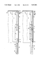
- FIGS. 5-5F depict the series of steps used to insert the embodiment of the circuit board shown in FIG. 3 into the embodiment of the card cage and motherboard of the embodiment of FIG. 2;
- FIGS. 6-6G depict the series of steps used to remove the embodiment of the circuit board of FIG. 2 from the embodiment of the motherboard of FIG. 2;
- FIG. 7 is a perspective view of another embodiment of a circuit board with a sliding rail and groove assembly having a bell crank and a card cage constructed in accordance with the invention.
- FIG. 8 is a perspective view of the device of FIG. 7, showing the circuit board with a circuit board pushed crank into a card cage by relative sliding of the rail and groove and aligned for mating with a motherboard;
- FIG. 9 is a perspective view of the device of FIG. 7, showing the circuit board with the bell crank activated to fully install and mate the circuit board with the motherboard;
- FIGS. 10, 11 and 12 show the stages of circuit board installation and connector coupling according to the present invention.
- FIG. 13 depicts an end view of the upper portion of an embodiment of the circuit board and cardcage of the system configured for increased circuit board surface utilization.
- the present invention contemplates a circuit board insertion and removal tool which permits insertion and removal in cramped overhead cages and in environment allowing good air circulation for cooling and further applies the insertion and removal forces directly between the male and female connector assembling to avoid board distortions.
- the card cage and motherboard assembly 30 includes a card cage 14 (shown in phantom) and a motherboard 16.
- the motherboard 16 is positioned at the bottom surface of the card cage 14.
- the motherboard 16 is constructed in the standard fashion, with several additional structures being used in aligning and inserting a printed circuit board.
- the motherboard may be closely spaced for high density packaging so that insufficient space is provided for using the approach of FIG. 1.
- a first tool alignment guide 32 having a lip 36 is positioned on the motherboard 16 and along one side of the connectors 18.
- the first tool alignment guide 32 serves to direct the circuit board removal-insertion tool during circuit board 12 insertion (Arrow I) and removal (Arrow R).
- a second tool alignment guide 34 Positioned on the other side of the connectors 18 from the first tool alignment guide 32 and approximately midway between the connectors 18 is a second tool alignment guide 34.
- the second alignment guide 34 constrains the circuit board removal-insertion tool to move along the first tool alignment guide 32 during circuit board removal and insertion.
- a forward retaining member 40 located toward the opening of the card cage 14 and laterally aligned approximately with the connectors 18, serves to retain the circuit board 68 during board insertion.
- a vertical alignment member 50 having a pair of alignment pins 52, one on each side, is located between the connectors 18, and serves to constrain the circuit board insertion and removal tool to move along the surface of the motherboard 16.
- a rear stop 60 provides a positive stop for the motion of the circuit board 12 during board removal.
- This form of card cage and motherboard makes possible the horizontal flow of air of homogeneous temperature from back to front through the card cage.
- air flow is important when multiple card cages are to be stacked in a vertical configuration.
- a source of air may be placed along the back of each card cage and the movement of air from back to front (Arrows A,A' in FIG. 2) insures each card cage will be cooled substantially equally.
- an embodiment of a circuit board 68 constructed in accordance with the invention includes a printed circuit board 12 having edge connectors 20.
- the edge connectors 20 are positioned on the edge of the printed circuit board 12 and spaced apart so as to mate with the motherboard connectors 18.
- a front force transfer member 70 having a pair of force transfer pins 72, extending one on each side.
- a rear force transfer member 80 having a pair of force transfer pins 82, again one extending from each side.
- the forward and rear force transfer members 70,80 convert forward horizontal motion of the circuit board 68 into downward vertical motion during board insertion and into upward vertical motion during board removal.
- the front force transfer member 70 extends below the rear force transfer member 80 and the force transfer pins 72 are positioned below the height of the force transfer pins 82.
- a circuit board reinforcement bar 90 is positioned near the lower edge of the circuit board 68, above the edge connectors 20 and serves to prevent board flexing during board insertion and removal.
- an embodiment of the circuit board removal insertion tool 100 in accordance with the invention includes a left 102 and a right 104 linear support member.
- the left 102 and right 104 linear support members are separated by a spring retaining member 110 located near one end of the linear support members 102,104.
- the spring retaining member 110 holds a bumper 118 biased by a spring 119 away from the spring retaining member 110.
- the bumper 118 pushes the circuit board 68 along during board insertion.
- the linear support members 102,104 are separated sufficiently so as to permit the forward retaining member 40, the vertical alignment member 50, and the connectors 18 of the motherboard 30 and the forward force transfer member 70, the rear force transfer member 80 and the edge connectors 20 of the circuit board 68 to pass between the linear support members 102,104 during board removal and insertion, while still permitting the linear support members 102,104 to move between the first 32 and second 34 tool alignment guides.
- the height of the linear support members 102,104 indicated by the dimension "h" is such that the left linear support member 102 can fit between the lip 36 of the first tool alignment guide 32 and the motherboard surface.
- a handle assembly 112 Adjacent the spring retaining member 110 and at the same end of the linear support members 102,104 is a handle assembly 112 projecting at approximately ninety degrees to the linear support members 102,104.
- the base of the handle assembly 114 and the spring retaining member 110 are secured to the linear support members 102,104 by bolts 116.
- Each of the linear support members 102,104 includes a pair of slots 130,132.
- the first slot 130 begins approximately midway along the linear support member 102 in a first receiving groove 140.
- the first receiving groove 140 is located at the top surface of the linear support member 104.
- the first slot 130 slopes toward the front edge 144 of the linear support member 104 and terminates in a first locating groove 142 positioned at about the middle of the front edge 144.
- the first receiving groove 140 is positioned so as to receive one of the force transfer pins 82 of the rear force transfer member 50 as the circuit board 68 is loaded in the tool 100 at the start of board insertion.
- the force transfer pin 82 moves, relative to the tool 100, from the first receiving groove 140 through the slot 130 through the first locating groove 142.
- the first locating groove 142 helps align the force transfer pin 82 of the rear force transfer member 80 with the first slot 130 and the force transfer pin 82 moves, relative to the tool 100, from the first locating groove 142 through the slot 130 to the first receiving groove 140.
- the second slot 132 begins in a second receiving groove 150 located at the upper surface of the linear support member 104 approximately adjacent the spring retaining member 110.
- the second slot 132 generally slopes toward the front edge 144 of the linear support member 104.
- the second slot 132 terminates in a second locating groove 152 at the front edge 144 of the linear support member 102 below the first locating groove 142.
- the second receiving groove 150 opens into a complex structure which will be discussed in more detail below.
- the second receiving groove 150 is located so as to receive one of the force transfer pins 72 of the front force transfer member 70 as the circuit board 68 is loaded in the tool 100 at the start of board insertion.
- the force transfer pins 72,82 extend from the force transfer members 70,80 sufficiently to engage the slots 132,130, while permitting the force transfer members 70,80 to pass between the linear support member 102,104.
- the force transfer pin 72 moves relative to the slot 132, from the second receiving groove 150 along the slot 132 through the second locating groove 152.
- the force transfer pin 72 moves, relative to the slot 132, from the second locating groove 152 to the second receiving groove 150.
- the second locating groove 152 helps align and engage both the force transfer pin 72 of the front force transfer member 70 and the alignment pin 52 of the vertical alignment member 50 with the second slot 132.
- the receiving groove 150 opens into an insertion groove 160 and a removal groove 162.
- the insertion groove 160 supports the force transfer pins 72 during board insertion and the removal groove 162 supports the force transfer pins 72 during board removal.
- These grooves 160,162 communicate with a sloping portion 154 of the slot 132.
- the sloping position 154 of the slot 132 in turn communicates with a horizontal portion 156 of the slot 132, which opens into the second locating groove 152.
- the circuit board 68 is first mounted in the tool 100 by placing the circuit board 68 between the two linear support members 102,104 and engaging the force transfer pin 72 on each side of the front force transfer member 70 with the insertion groove 160 of the second receiving groove 150 in the linear support members 102,104.
- each force transfer pin 82 on each side of the rear force transfer member 80 engages with the first receiving groove 140 in the linear support members 102,104.
- the front edge 144 of the left support member 102 of the tool 100 is positioned to slide below the lip 36 of the tool alignment guide 32.
- the tool 100 is oriented such that the forward retaining member 40 and the forward connector 18 are positioned between the two linear support members 102,104.
- the vertical alignment member 50 also is positioned between the linear support members 102,104, and the second locating groove 152 engages the alignment pins 52 of the vertical alignment member 50.
- the front force transfer member 70 rides over the forward retaining member 40, owing to the sloping engagement surfaces 41,71 on each member.
- the circuit board connectors 20 are aligned with the motherboard connectors 18 and the rear force transfer member 80 is aligned with the vertical alignment member 50.
- the tool 100 is then moved backward, out of the card cage and motherboard 30.
- the vertical surface 73 of the front force transfer member 70 is prevented from moving backward along with the tool 100 by the vertical surface 43 of the forward retaining member 40.
- the engagement of these surfaces 43,73 retains the circuit board 68 within the card cage and motherboard 30 as the tool 100 is removed.
- each slot 132,130 imparts a downward component of force on each of the force transfer pins 72,82 as the tool 100 is moved backward, owing to the retention of the circuit board 68 by the forward retaining member 40. This downward component of force pushes the circuit board edge connectors 2 into the motherboard connectors 18.
- the slope of the sloping portion 154 of slot 132 is such that once the connectors 18,20 seat, the sloping portion 154 becomes the horizontal portion 156, permitting the force transfer pins 72 to experience no downward component of force and to slide along the slot 132 and out through the second locating groove 152.
- the slope of the slot 130 is also such that once the connectors 18,20 seat, the force transfer pins 82 exit through the first locating groove 142. Once the force transfer pins 72 exit through the second locating groove 152, the tool 100 is free from the motherboard (FIG. 5F).
- a feature of this arrangement is that the tool, in applying the insertion force, acts to pull the circuit board pins and the motherboard connector together with a lever action in which the fulcrum extends across the entire length of the connector.
- This is distinguished from the prior art in which the circuit board is pushed into the motherboard.
- the force needed to insert the card pins into the connectors on the motherboard is transferred through the printed circuit board causing the circuit board to bow and risk being damaged.
- the pulling together function of the present invention avoids the problem of board flexing or bowing.
- the front edge 144 of the left support member 102 of the tool 100 is positioned to slide below the lip 36 of the alignment guide 32 (FIG. 6).
- the tool 100 is again oriented such that the forward retaining member 40 and the forward connector 18 are positioned between the two linear support members 102,104.
- the force transfer pins 72 of the front force transfer member 70 engage the second locating groove 152 and move along the horizontal portion 156 of slot 132.
- the vertical alignment member 50 also is positioned between the linear support members 102,104, and the second locating groove 152 engages the alignment pins 52 of the vertical alignment member 50 (FIG. 6A).
- the force transfer pins 82 of the rear force transfer member 80 engage the first locating groove 142.
- the force transfer pins 72 of the front force transfer member 70 reach the sloping portion 154 of the slot 132 as the force transfer pins 82 pass through the first location groove 42 and engage the slot 130.
- the force transfer pins 72, 82 of the front 70 and rear 80 force transfer members respectively slide along the slots 130,132 respectively.
- the lower edge of each slot 130,132 imparts an upward component of force on each of the force transfer pins 72,82 as the tool 100 is moved forward. This upward component of force separates the circuit board edge connectors 20 from the motherboard connectors 18.
- the slope of the sloping portion of slot 132 is again such that once the connectors 18,20 separate, the force transfer pins 72 move from the sloping portion 154 of slot 132 into the second receiving groove 150.
- the slope of the slot 130 is such that once the connectors 18,20 separate, the force transfer pins 82 move from the slot 132 into the first receiving groove 140 (FIG. 6C).
- the tool 100 is moved slightly further forward, causing the bumper 118 to press against the forward retaining member 40, compress the spring 119 and force the circuit board 68 against the stop 60.
- the force transfer pins 72 ride up the slope 161 (FIG. 6D) from the insertion groove 160 into the retaining groove 162 (FIG. 6E).
- the retaining groove 162 is located sufficiently high in the support member 102,104 that the base 74 of the front force transfer member 70 is supported above the top 44 of the retaining member 40. This permits the circuit board 68 to be removed, along with the tool 100, from the motherboard (FIGS. 6F and 6G).
- circuit board 68 may be removed from the tool 100 by lifting the circuit board 68 and permitting the force transfer pins 72,82 to lift from the receiving grooves 150,140 respectively.
- FIG. 7 Another embodiment of the invention which incorporates, on the circuit board itself the mechanism to insert the circuit board edge connectors into the motherboard connectors, is depicted in FIG. 7.
- FIG. 7 a further embodiment of the invention is illustrated with a card cage 234, a motherboard 236, and a circuit board 238 with a crank with lever 264 operative to raise and lower a rail 250.
- the motherboard 236 is positioned at the bottom of the card cage 234.
- the motherboard 236 and card cage 234 are constructed in the standard fashion, incorporating several additional structures to ensure precise alignment and stability of the circuit board with a crank 264 upon installation in the cage and mating with the motherboard.
- a lower grooved guide track 240 and an upper guide track 242 provide alignment of the card by accepting the rail 250 and upper card edge 252.
- the lower guide track 240 is positioned on or close to the motherboard 236 and along one side of the motherboard connectors 244.
- the lower guide track 240 has lips 246 defining an open, "T" shaped channel 248 able to receive a guide member or rail 250, which is "T" shaped to allow it to slide within the channel 248 without slipping out under insertion and removal pressures as described below.
- the preferred guide member 250 is small enough to slide freely along the axis of the lower guide track 240 yet large enough to move with minimal vertical and horizontal play and be precluded from being laterally withdrawn from the channel 248.
- the optional upper guide track 242 at the top of the card cage 234 aligns the circuit board 238 providing lateral stability to the top of the circuit board 252 both during insertion and removal of the board assembly 238, and while the board 238 is in place within the card cage 234.
- the upper guide track 242 has two parallel walls 254 separated by sufficient distance such that the upper edge of the circuit board 252 moves freely in the channel therebetween, but close enough together so that an acceptable limit to lateral movement at the top of the circuit board 252 is obtained.
- the depth of the guide track 242 is sufficient to retain the circuit board 252 throughout its entire range of vertical motion during insertion and removal.
- the rail 250 is separated as opposite ends from board 238 by crank 264 and a curved link 266 through pivotal connections to the circuit board 252 and the guide rail 250 to form a pivoting parallelogram.
- the crank lever 264 has a pin joint pivot 268 on the circuit board 252 and a second pin joint pivot 270 to rail 250.
- Link 266 has corresponding pivots 274 and 272.
- the length of the crank 264 and placement of the fulcrum pin joint 268 is such that a significant mechanical advantage is created in the application of force to the guide rail 250 from motion of the crank 264. This mechanically enhanced force is conveyed from the rail 250 to guide 240.
- a rear stop block 256 is positioned on the motherboard 236 to limit the travel of the printed circuit board 238 upon its insertion into the cage 234, by engaging a rear stop block 260 on circuit board 238.
- the board 238 is thus stopped with circuit board connectors 258 aligned with motherboard connectors 244 to allow the pins to be coupled without damage.
- the rear stop block 256 may be anchored to or a part of the cage 234.
- a motherboard forward stop block 257 is positioned on the motherboard 236 to limit the travel of the printed circuit board 238 upon its removal from the cage 234, by engaging a circuit board forward stop block 261 on circuit board 238.
- the board 238 is thus stopped with circuit board connectors 258 aligned with motherboard connectors 244 to allow the pins to be decoupled without damage.
- the motherboard forward stop block 257 is an L-shaped member located adjacent the front connector 244.
- the combination of motherboard forward stop block 257, front connector 244 and guide rail 240 defines a slot 259 into which the circuit board forward stop block 261 on the circuit board 238 engages when the circuit board 238 is coupled.
- the height of the L-shaped motherboard forward stop block 257 and the depth of the circuit board forward stop block 261 are chosen such that when the connectors 244,258 are decoupled, the circuit board forward stop block 257 may pass over the motherboard forward stop block 26 to permit circuit board insertion and removal.
- the circuit board 238 with crank 264 is shown inserted into the card cage 234, with rail 250 in the channel of guide 240 and portion 252 in track 240.
- the circuit board connectors 258 are placed in position for mating with the motherboard connectors 244, with rear block 260 against rear block 256 and the crank 264 fully pulled out. In this position, the circuit board forward stop block 261 has passed over the motherboard forward stop block 257. Due to the positioning of the blocks 256, 260, the circuit board connectors 258 and the motherboard connectors 244 are correctly aligned for mating. It is envisaged that second block could be a flange on the circuit board 252 or even the edge of the circuit board 252 itself.
- crank 264 has been pushed vertical against board 238. This has forced connectors 258 and 244 together by the force transfer between rail 250 and guide 240, and caused the forward stop block 261 of the circuit board to engage the slot 259 formed in part by the motherboard forward stop block 257.
- FIGS. 10-12 shown from, the opposite side of the circuit board 238 with crank 264 the process of insertion, or removal when reversed, is shown using the invention.
- the board 238 is ready for insertion into the cage (or has been fully withdrawn).
- FIG. 12 shows the circuit board with crank 238 raised to vertical, engaging the circuit board forward stop block 261 with the slot 259 formed in part by the motherboard forward stop block 257, and forcing the connectors and pins into contact achieving a fully installed position (or ready to have the crank 264 lowered to revert to the FIG. 4 condition).
- the circuit board 68 can not have components 10 located too close to the edge of the circuit board 68 which is opposite to the edge to which the connectors 20 are attached.
- the reason for this is that the circuit board 68, during insertion into and removal from the cardcage 14, is moved in a direction perpendicular to the direction of removal or insertion.
- the tracks 17 on the side of the cardcage 14 opposite to the side with the motherboard 16 must be sufficiently deep to permit the circuit board 68 to remain engaged between the tracks 17 both during insertion and when the circuit board 68 is fully inserted.
- FIG. 13 an embodiment of the circuit board 68 of the system is shown which permits an increased utilization of the surface area of the circuit board 68.
- the upper track 17 of the cardcage 14 is replaced with a spacer track 17' and a spacer 290 is attached to the edge of the circuit board 68.
- the spacer track 17' may simply take the form of an inverted-U, while the spacer 290 takes the form of an inverted-J.
- the base of the inverted-J of the spacer 290 is sized to fit with the base of the inverted-U of the track 17'.
- the inverted-J of the spacer 290 is attached to the edge of the circuit board 68, in the embodiment shown, by a screw 294 and nut 296, but other methods of attachment may be used.
- the spacer 290 is separated from the circuit board 68 by a separator 292.
- the spacer 290 engages the spacer track 17' near the open edge of the spacer track 290.
- the circuit board 68 moves up into the spacer track 17' as shown in phantom 300. Because the spacer 290 extends beyond the edge of the circuit board 68 and away from the surface of the circuit board 68, more surface space on the circuit board 68 may be allocated for components as shown in phantom 10'. Thus, less of the circuit board space is wasted without compromising the support normally provided by the upper tracks 17 of the cardcage 14.
Abstract
Description
Claims (19)
Priority Applications (1)
| Application Number | Priority Date | Filing Date | Title |
|---|---|---|---|
| US08/047,139 US5317481A (en) | 1991-06-13 | 1993-04-13 | Circuit board and insertion tool |
Applications Claiming Priority (3)
| Application Number | Priority Date | Filing Date | Title |
|---|---|---|---|
| US71510291A | 1991-06-13 | 1991-06-13 | |
| US07/860,191 US5238423A (en) | 1991-06-13 | 1992-03-26 | Circuit board and insertion tool |
| US08/047,139 US5317481A (en) | 1991-06-13 | 1993-04-13 | Circuit board and insertion tool |
Related Parent Applications (1)
| Application Number | Title | Priority Date | Filing Date |
|---|---|---|---|
| US07/860,191 Division US5238423A (en) | 1991-06-13 | 1992-03-26 | Circuit board and insertion tool |
Publications (1)
| Publication Number | Publication Date |
|---|---|
| US5317481A true US5317481A (en) | 1994-05-31 |
Family
ID=46247280
Family Applications (1)
| Application Number | Title | Priority Date | Filing Date |
|---|---|---|---|
| US08/047,139 Expired - Fee Related US5317481A (en) | 1991-06-13 | 1993-04-13 | Circuit board and insertion tool |
Country Status (1)
| Country | Link |
|---|---|
| US (1) | US5317481A (en) |
Cited By (40)
| Publication number | Priority date | Publication date | Assignee | Title |
|---|---|---|---|---|
| US5535100A (en) * | 1995-06-07 | 1996-07-09 | International Business Machines Corporation | Snap-together/quick-release fastening assembly for supporting a circuit card |
| GB2303742A (en) * | 1995-07-26 | 1997-02-26 | Aeg Schneider Automation | Device for insertion and removal of a PCB |
| US5673174A (en) * | 1995-03-23 | 1997-09-30 | Nexar Technologies, Inc. | System permitting the external replacement of the CPU and/or DRAM SIMMs microchip boards |
| US5751559A (en) * | 1996-10-08 | 1998-05-12 | International Business Machines Corporation | Apparatus for inserting PC cards having recessed guide paths with multiple levels in the guide paths |
| US5815377A (en) * | 1997-12-08 | 1998-09-29 | International Business Machines Corporation | Apparatus for auto docking PCI cards |
| US5868585A (en) * | 1996-12-13 | 1999-02-09 | International Business Machines Corporation | System and method for inserting circuit boards in tight spaces |
| US5943218A (en) * | 1998-06-01 | 1999-08-24 | Liu; Yen-Wen | Card type CPU-fixing structure |
| US6053760A (en) * | 1998-06-05 | 2000-04-25 | International Business Machines Corporation | Universal device for mounting circuit cards in a computer or like electrical machine |
| US6062894A (en) * | 1998-10-30 | 2000-05-16 | International Business Machines Corporation | System and method for inserting circuit boards in tight spaces |
| US6071143A (en) * | 1996-12-13 | 2000-06-06 | International Business Machines Corporation | Cabinet for insertion of circuit boards in tight spaces |
| US6226188B1 (en) | 1998-08-10 | 2001-05-01 | James F. Warren | Modular integrated pneumatic connection device |
| US6373712B1 (en) | 1998-06-05 | 2002-04-16 | International Business Machines Corporation | Device for inserting circuit cards into electrical machines |
| US6406322B1 (en) | 2001-08-29 | 2002-06-18 | International Business Machines Corporation | Easy load cartridge for carrying and inserting cards into printed circuit boards |
| US6411517B1 (en) * | 1998-04-16 | 2002-06-25 | Trioniq Inc. | Circuit card insertion and removal system |
| US20020125039A1 (en) * | 1999-05-25 | 2002-09-12 | Marketkar Nandu J. | Electromagnetic coupler alignment |
| JP2003037378A (en) * | 2001-07-25 | 2003-02-07 | Hitachi Kokusai Electric Inc | Enclosure structure for electronic equipment |
| US6529383B1 (en) | 2001-08-29 | 2003-03-04 | International Business Machines Corporation | Docking cartridge for insertion and removal of electronic circuit cards |
| WO2003041470A1 (en) * | 2001-11-08 | 2003-05-15 | Sun Microsystems, Inc. | Rack-mountable systems |
| US6570771B2 (en) * | 1996-08-29 | 2003-05-27 | Micron Technology, Inc. | Single-piece molded module housing |
| US6597581B2 (en) | 2001-08-29 | 2003-07-22 | International Business Machines Corporation | Single-sided cartridge guide mechanism |
| US6606255B2 (en) | 2001-08-29 | 2003-08-12 | International Business Machines Corporation | Mechanism for plugging planar boards |
| US6625039B2 (en) | 2001-08-29 | 2003-09-23 | International Business Machines Corporation | EMI spring configuration |
| US6709276B2 (en) | 2001-08-29 | 2004-03-23 | International Business Machines Corporation | Pluggable planar board |
| US20040111879A1 (en) * | 2002-12-13 | 2004-06-17 | Ramirez Carlos E. | Circuit board component installation tools and methods of using |
| WO2004084014A2 (en) * | 2003-03-17 | 2004-09-30 | Unisys Corporation | Computer system and method configured for improved cooling |
| US20040264123A1 (en) * | 2003-06-26 | 2004-12-30 | International Business Machines Corporation | Server packaging architecture utilizing a blind docking processor-to-midplane mechanism |
| US20050130458A1 (en) * | 2002-12-30 | 2005-06-16 | Simon Thomas D. | Electromagnetic coupler registration and mating |
| US20060082421A1 (en) * | 2002-06-05 | 2006-04-20 | Simon Thomas D | Controlling coupling strength in electromagnetic bus coupling |
| US7112084B1 (en) * | 2003-03-17 | 2006-09-26 | Unisys Corporation | Method and apparatus for installing a printed circuit assembly within a chassis of a computer system |
| US7283371B1 (en) | 2004-03-12 | 2007-10-16 | Sun Microsystems, Inc. | Device carrier system |
| US20080264192A1 (en) * | 2007-04-30 | 2008-10-30 | Christensen Steven M | Printed Circuit Board Engagement Systems and Methods |
| US20090078068A1 (en) * | 2007-09-26 | 2009-03-26 | International Business Machines Corporation | Actuation device having combined mechanisms to match a desired connector plugging curve and method for actuating a power supply therewith |
| US20090163046A1 (en) * | 2004-11-05 | 2009-06-25 | Adc Gmbh | Distribution board connection module |
| US20090166833A1 (en) * | 2007-12-28 | 2009-07-02 | Hon Hai Precision Industry Co., Ltd. | Semiconductor unit which includes multiple chip packages integrated together |
| US20090215303A1 (en) * | 2008-02-22 | 2009-08-27 | International Business Machines Corporation | Connector actuation mechanism |
| US7654844B1 (en) * | 2008-08-22 | 2010-02-02 | International Business Machines Corporation | Telescopic power connector |
| US7742292B1 (en) | 2004-03-12 | 2010-06-22 | Sun Microsystems, Inc. | Component array bracket assembly |
| US20130033832A1 (en) * | 2010-03-18 | 2013-02-07 | Xiao-Zhu Chen | Mounting apparatus for pci card |
| US20140168891A1 (en) * | 2012-12-14 | 2014-06-19 | Kevin Mundt | Telescoping enclosure for information handling system component |
| US9356381B2 (en) * | 2014-09-19 | 2016-05-31 | Tyco Electronics Corporation | Protective cover configured to cover a mating interface of an electrical connector |
Citations (22)
| Publication number | Priority date | Publication date | Assignee | Title |
|---|---|---|---|---|
| US3178214A (en) * | 1963-07-30 | 1965-04-13 | Gen Electric | Extractor for removing printed circuit boards from a rack |
| US3335386A (en) * | 1964-11-19 | 1967-08-08 | Admiral Corp | Locking device for printed circuit modules |
| US3476258A (en) * | 1967-05-18 | 1969-11-04 | Friden Inc | Board insertion and extraction system |
| US3484129A (en) * | 1968-01-10 | 1969-12-16 | Sherman G Askren | Universal extractor tool |
| US3617083A (en) * | 1969-12-18 | 1971-11-02 | Gte Automatic Electric Lab Inc | Tool for extracting printed circuit cards from card files |
| US3903576A (en) * | 1974-10-01 | 1975-09-09 | Bendix Corp | Apparatus for extracting circuit cards from chassis |
| US3944311A (en) * | 1974-09-04 | 1976-03-16 | Burroughs Corporation | Printed circuit card interface apparatus |
| US4223934A (en) * | 1978-07-24 | 1980-09-23 | Bell Telephone Laboratories, Incorporated | Tool to insert and extract printed circuit boards into and out of apparatus housing connectors |
| US4243283A (en) * | 1979-09-17 | 1981-01-06 | Rca Corporation | Circuit board guide and ground connector |
| US4352533A (en) * | 1978-10-31 | 1982-10-05 | Fujitsu Limited | Connector device for printed boards |
| US4367583A (en) * | 1981-03-12 | 1983-01-11 | Litton Systems, Inc. | Connector mounting press |
| US4445740A (en) * | 1982-04-26 | 1984-05-01 | Rockwell International Corporation | Circuit board assembly |
| US4454552A (en) * | 1982-05-17 | 1984-06-12 | General Electric Company | Printed circuit board connection system |
| US4480884A (en) * | 1983-07-01 | 1984-11-06 | International Business Machines Corporation | Zero insertion force connector and circuit card assembly |
| US4553322A (en) * | 1984-05-16 | 1985-11-19 | Amp Incorporated | Floating locator head for application tooling |
| US4631637A (en) * | 1985-12-23 | 1986-12-23 | Burroughs Corporation | Dual backplane interconnect system |
| US4692120A (en) * | 1986-10-01 | 1987-09-08 | Feinstein David Y | Electronic card for sharing the same edgeboard connector with another electronic edgeboard |
| US4731924A (en) * | 1986-08-04 | 1988-03-22 | American Telephone And Telegraph Company | Method and apparatus for inserting multi-leaded articles into a substrate |
| US4778401A (en) * | 1987-05-28 | 1988-10-18 | Digital Equipment Corporation | Extraction-insertion card guide mechanism |
| US4850884A (en) * | 1986-12-04 | 1989-07-25 | Yazaki Corporation | Controller-including wiring apparatus for automotive vehicle |
| US4869675A (en) * | 1987-02-12 | 1989-09-26 | Yazaki Corporation | Electrical connector for vehicles |
| US4917616A (en) * | 1988-07-15 | 1990-04-17 | Amp Incorporated | Backplane signal connector with controlled impedance |
-
1993
- 1993-04-13 US US08/047,139 patent/US5317481A/en not_active Expired - Fee Related
Patent Citations (22)
| Publication number | Priority date | Publication date | Assignee | Title |
|---|---|---|---|---|
| US3178214A (en) * | 1963-07-30 | 1965-04-13 | Gen Electric | Extractor for removing printed circuit boards from a rack |
| US3335386A (en) * | 1964-11-19 | 1967-08-08 | Admiral Corp | Locking device for printed circuit modules |
| US3476258A (en) * | 1967-05-18 | 1969-11-04 | Friden Inc | Board insertion and extraction system |
| US3484129A (en) * | 1968-01-10 | 1969-12-16 | Sherman G Askren | Universal extractor tool |
| US3617083A (en) * | 1969-12-18 | 1971-11-02 | Gte Automatic Electric Lab Inc | Tool for extracting printed circuit cards from card files |
| US3944311A (en) * | 1974-09-04 | 1976-03-16 | Burroughs Corporation | Printed circuit card interface apparatus |
| US3903576A (en) * | 1974-10-01 | 1975-09-09 | Bendix Corp | Apparatus for extracting circuit cards from chassis |
| US4223934A (en) * | 1978-07-24 | 1980-09-23 | Bell Telephone Laboratories, Incorporated | Tool to insert and extract printed circuit boards into and out of apparatus housing connectors |
| US4352533A (en) * | 1978-10-31 | 1982-10-05 | Fujitsu Limited | Connector device for printed boards |
| US4243283A (en) * | 1979-09-17 | 1981-01-06 | Rca Corporation | Circuit board guide and ground connector |
| US4367583A (en) * | 1981-03-12 | 1983-01-11 | Litton Systems, Inc. | Connector mounting press |
| US4445740A (en) * | 1982-04-26 | 1984-05-01 | Rockwell International Corporation | Circuit board assembly |
| US4454552A (en) * | 1982-05-17 | 1984-06-12 | General Electric Company | Printed circuit board connection system |
| US4480884A (en) * | 1983-07-01 | 1984-11-06 | International Business Machines Corporation | Zero insertion force connector and circuit card assembly |
| US4553322A (en) * | 1984-05-16 | 1985-11-19 | Amp Incorporated | Floating locator head for application tooling |
| US4631637A (en) * | 1985-12-23 | 1986-12-23 | Burroughs Corporation | Dual backplane interconnect system |
| US4731924A (en) * | 1986-08-04 | 1988-03-22 | American Telephone And Telegraph Company | Method and apparatus for inserting multi-leaded articles into a substrate |
| US4692120A (en) * | 1986-10-01 | 1987-09-08 | Feinstein David Y | Electronic card for sharing the same edgeboard connector with another electronic edgeboard |
| US4850884A (en) * | 1986-12-04 | 1989-07-25 | Yazaki Corporation | Controller-including wiring apparatus for automotive vehicle |
| US4869675A (en) * | 1987-02-12 | 1989-09-26 | Yazaki Corporation | Electrical connector for vehicles |
| US4778401A (en) * | 1987-05-28 | 1988-10-18 | Digital Equipment Corporation | Extraction-insertion card guide mechanism |
| US4917616A (en) * | 1988-07-15 | 1990-04-17 | Amp Incorporated | Backplane signal connector with controlled impedance |
Cited By (65)
| Publication number | Priority date | Publication date | Assignee | Title |
|---|---|---|---|---|
| US5673174A (en) * | 1995-03-23 | 1997-09-30 | Nexar Technologies, Inc. | System permitting the external replacement of the CPU and/or DRAM SIMMs microchip boards |
| US5535100A (en) * | 1995-06-07 | 1996-07-09 | International Business Machines Corporation | Snap-together/quick-release fastening assembly for supporting a circuit card |
| GB2303742A (en) * | 1995-07-26 | 1997-02-26 | Aeg Schneider Automation | Device for insertion and removal of a PCB |
| US6781848B2 (en) | 1996-08-29 | 2004-08-24 | Micron Technology, Inc. | Single-piece molded module housing |
| US20030193788A1 (en) * | 1996-08-29 | 2003-10-16 | Farnworth Warren M. | Single-piece molded module housing |
| US6570771B2 (en) * | 1996-08-29 | 2003-05-27 | Micron Technology, Inc. | Single-piece molded module housing |
| US5751559A (en) * | 1996-10-08 | 1998-05-12 | International Business Machines Corporation | Apparatus for inserting PC cards having recessed guide paths with multiple levels in the guide paths |
| US6071143A (en) * | 1996-12-13 | 2000-06-06 | International Business Machines Corporation | Cabinet for insertion of circuit boards in tight spaces |
| US5868585A (en) * | 1996-12-13 | 1999-02-09 | International Business Machines Corporation | System and method for inserting circuit boards in tight spaces |
| US5815377A (en) * | 1997-12-08 | 1998-09-29 | International Business Machines Corporation | Apparatus for auto docking PCI cards |
| US6411517B1 (en) * | 1998-04-16 | 2002-06-25 | Trioniq Inc. | Circuit card insertion and removal system |
| USRE45034E1 (en) * | 1998-04-16 | 2014-07-22 | International Business Machines Corporation | Circuit card insertion and removal system |
| US5943218A (en) * | 1998-06-01 | 1999-08-24 | Liu; Yen-Wen | Card type CPU-fixing structure |
| US6053760A (en) * | 1998-06-05 | 2000-04-25 | International Business Machines Corporation | Universal device for mounting circuit cards in a computer or like electrical machine |
| US6373712B1 (en) | 1998-06-05 | 2002-04-16 | International Business Machines Corporation | Device for inserting circuit cards into electrical machines |
| US6226188B1 (en) | 1998-08-10 | 2001-05-01 | James F. Warren | Modular integrated pneumatic connection device |
| US6062894A (en) * | 1998-10-30 | 2000-05-16 | International Business Machines Corporation | System and method for inserting circuit boards in tight spaces |
| US6836016B2 (en) * | 1999-05-25 | 2004-12-28 | Intel Corporation | Electromagnetic coupler alignment |
| US20020125039A1 (en) * | 1999-05-25 | 2002-09-12 | Marketkar Nandu J. | Electromagnetic coupler alignment |
| JP4518709B2 (en) * | 2001-07-25 | 2010-08-04 | 株式会社日立国際電気 | Electronic equipment housing structure |
| JP2003037378A (en) * | 2001-07-25 | 2003-02-07 | Hitachi Kokusai Electric Inc | Enclosure structure for electronic equipment |
| US6529383B1 (en) | 2001-08-29 | 2003-03-04 | International Business Machines Corporation | Docking cartridge for insertion and removal of electronic circuit cards |
| US6406322B1 (en) | 2001-08-29 | 2002-06-18 | International Business Machines Corporation | Easy load cartridge for carrying and inserting cards into printed circuit boards |
| US6709276B2 (en) | 2001-08-29 | 2004-03-23 | International Business Machines Corporation | Pluggable planar board |
| US6625039B2 (en) | 2001-08-29 | 2003-09-23 | International Business Machines Corporation | EMI spring configuration |
| US6606255B2 (en) | 2001-08-29 | 2003-08-12 | International Business Machines Corporation | Mechanism for plugging planar boards |
| US6597581B2 (en) | 2001-08-29 | 2003-07-22 | International Business Machines Corporation | Single-sided cartridge guide mechanism |
| WO2003041470A1 (en) * | 2001-11-08 | 2003-05-15 | Sun Microsystems, Inc. | Rack-mountable systems |
| US20050117316A1 (en) * | 2001-11-08 | 2005-06-02 | Wrycraft Sean C. | Rack-mountable systems |
| US7411470B2 (en) | 2002-06-05 | 2008-08-12 | Intel Corporation | Controlling coupling strength in electromagnetic bus coupling |
| US7649429B2 (en) | 2002-06-05 | 2010-01-19 | Intel Corporation | Controlling coupling strength in electromagnetic bus coupling |
| US20060082421A1 (en) * | 2002-06-05 | 2006-04-20 | Simon Thomas D | Controlling coupling strength in electromagnetic bus coupling |
| US20080266017A1 (en) * | 2002-06-05 | 2008-10-30 | Intel Corporation | Controlling coupling strength in electromagnetic bus coupling |
| US7886430B2 (en) | 2002-12-13 | 2011-02-15 | Hewlett-Packard Development Company, L.P. | Method of installing circuit board component |
| US20040111879A1 (en) * | 2002-12-13 | 2004-06-17 | Ramirez Carlos E. | Circuit board component installation tools and methods of using |
| US20050130458A1 (en) * | 2002-12-30 | 2005-06-16 | Simon Thomas D. | Electromagnetic coupler registration and mating |
| US20070287325A1 (en) * | 2002-12-30 | 2007-12-13 | Intel Corporation | Electromagnetic Coupler Registration and Mating |
| US7815451B2 (en) | 2002-12-30 | 2010-10-19 | Intel Corporation | Electromagnetic coupler registration and mating |
| US7252537B2 (en) | 2002-12-30 | 2007-08-07 | Intel Corporation | Electromagnetic coupler registration and mating |
| US6987667B1 (en) | 2003-03-17 | 2006-01-17 | Unisys Corporation | Computer system and method configured for improved cooling |
| WO2004084014A2 (en) * | 2003-03-17 | 2004-09-30 | Unisys Corporation | Computer system and method configured for improved cooling |
| US7112084B1 (en) * | 2003-03-17 | 2006-09-26 | Unisys Corporation | Method and apparatus for installing a printed circuit assembly within a chassis of a computer system |
| WO2004084014A3 (en) * | 2003-03-17 | 2004-12-09 | Unisys Corp | Computer system and method configured for improved cooling |
| US7180753B2 (en) * | 2003-06-26 | 2007-02-20 | International Business Machines Corporation | Server packaging architecture utilizing a blind docking processor-to-midplane mechanism |
| US20040264123A1 (en) * | 2003-06-26 | 2004-12-30 | International Business Machines Corporation | Server packaging architecture utilizing a blind docking processor-to-midplane mechanism |
| US7742292B1 (en) | 2004-03-12 | 2010-06-22 | Sun Microsystems, Inc. | Component array bracket assembly |
| US7283371B1 (en) | 2004-03-12 | 2007-10-16 | Sun Microsystems, Inc. | Device carrier system |
| US20090163046A1 (en) * | 2004-11-05 | 2009-06-25 | Adc Gmbh | Distribution board connection module |
| US7811107B2 (en) * | 2004-11-05 | 2010-10-12 | Adc Gmbh | Distribution board connection module |
| US7581959B2 (en) * | 2007-04-30 | 2009-09-01 | Newlsys, Inc. | Printed circuit board engagement systems and methods |
| US20080264192A1 (en) * | 2007-04-30 | 2008-10-30 | Christensen Steven M | Printed Circuit Board Engagement Systems and Methods |
| US7997918B2 (en) | 2007-09-26 | 2011-08-16 | International Business Machines Corporation | Actuation device having combined mechanisms to match a desired connector plugging curve and method for actuating a power supply therewith |
| US20090078068A1 (en) * | 2007-09-26 | 2009-03-26 | International Business Machines Corporation | Actuation device having combined mechanisms to match a desired connector plugging curve and method for actuating a power supply therewith |
| US20090166833A1 (en) * | 2007-12-28 | 2009-07-02 | Hon Hai Precision Industry Co., Ltd. | Semiconductor unit which includes multiple chip packages integrated together |
| US20090215303A1 (en) * | 2008-02-22 | 2009-08-27 | International Business Machines Corporation | Connector actuation mechanism |
| US20100221944A1 (en) * | 2008-02-22 | 2010-09-02 | International Business Machines Corporation | Connector actuation mechanism |
| US7874862B2 (en) | 2008-02-22 | 2011-01-25 | International Business Machines Corporation | Connector actuation mechanism |
| US7766684B2 (en) | 2008-02-22 | 2010-08-03 | International Business Machines Corporation | Connector actuation mechanism |
| US20100048037A1 (en) * | 2008-08-22 | 2010-02-25 | International Business Machines Corporation | Telescopic power connector |
| US7654844B1 (en) * | 2008-08-22 | 2010-02-02 | International Business Machines Corporation | Telescopic power connector |
| US20130033832A1 (en) * | 2010-03-18 | 2013-02-07 | Xiao-Zhu Chen | Mounting apparatus for pci card |
| US20140168891A1 (en) * | 2012-12-14 | 2014-06-19 | Kevin Mundt | Telescoping enclosure for information handling system component |
| US9383786B2 (en) * | 2012-12-14 | 2016-07-05 | Dell Products L.P. | Telescoping enclosure for information handling system component |
| US10001820B2 (en) | 2012-12-14 | 2018-06-19 | Dell Products L.P. | Telescoping enclosure for information handling system component |
| US9356381B2 (en) * | 2014-09-19 | 2016-05-31 | Tyco Electronics Corporation | Protective cover configured to cover a mating interface of an electrical connector |
Similar Documents
| Publication | Publication Date | Title |
|---|---|---|
| US5317481A (en) | Circuit board and insertion tool | |
| US5238423A (en) | Circuit board and insertion tool | |
| US4445740A (en) | Circuit board assembly | |
| KR100351595B1 (en) | An apparatus for retaining a card in a computer and computer using the same | |
| US6071143A (en) | Cabinet for insertion of circuit boards in tight spaces | |
| EP0293215B1 (en) | Extraction-insertion card guide mechanism | |
| US4614389A (en) | Circuit board assembly for accurate insertion | |
| US5868585A (en) | System and method for inserting circuit boards in tight spaces | |
| US5815377A (en) | Apparatus for auto docking PCI cards | |
| US7448912B1 (en) | Multi-in-one card connector that allows insertion of only one single card at a time | |
| US3944311A (en) | Printed circuit card interface apparatus | |
| US10320100B2 (en) | Card edge connector assembly | |
| US6975519B2 (en) | Insertion and extraction mechanism for circuit boards | |
| US7473039B2 (en) | Axis translation installation mechanism for optoelectronics modules and method | |
| CN108736227A (en) | Twin connectors system | |
| EP3229102A1 (en) | Component carrier | |
| US11596078B2 (en) | System and method for connecting at least one electronic card to a printed circuit board | |
| US6282099B1 (en) | Structure for mounting and method for installing a circuit card | |
| US5268821A (en) | Shared pc board ejector/injector tool | |
| CN109742639B (en) | SIM card plug-in mechanism | |
| US7507102B1 (en) | Method for horizontal installation of LGA socketed chips | |
| US4797786A (en) | Substrate mounting device | |
| US20040257777A1 (en) | Electronic system with a movable printed circuit assembly | |
| US4797784A (en) | Substrate mounting device | |
| US20030114035A1 (en) | Coverless ZIF socket for mounting an integrated circuit package on a circuit board |
Legal Events
| Date | Code | Title | Description |
|---|---|---|---|
| AS | Assignment |
Owner name: RTPC CORPORATION, DELAWARE Free format text: ASSIGNMENT OF 1% OF ASSIGNOR'S INTEREST;ASSIGNOR:RTMC CORPORATION;REEL/FRAME:007824/0938 Effective date: 19960208 Owner name: TM PATENTS, L.P., DELAWARE Free format text: ASSIGNOR HAS ASSIGNED TO ASSIGNEE, PURSUANT TO THE ASSIGNMENT, A 1% INTEREST IN THE PATENTS, PATENT APPLICATIONS AND OTHER PROPERTY DESCRIBED IN THE ASSIGNMENT;ASSIGNOR:RTPC CORPORATION;REEL/FRAME:007833/0001 Effective date: 19960208 Owner name: TM PATENTS, L.P., DELAWARE Free format text: ASSIGNMENT OF A 99% INTEREST;ASSIGNOR:RTMC CORPORATION;REEL/FRAME:007833/0719 Effective date: 19960208 Owner name: TMC CREDITORS, LLC, MASSACHUSETTS Free format text: SECURITY INTEREST;ASSIGNOR:TM PATENTS, L.P.;REEL/FRAME:007824/0887 Effective date: 19960208 |
|
| AS | Assignment |
Owner name: TM CREDITORS, LLC, MASSACHUSETTS Free format text: SECURITY INTEREST;ASSIGNOR:TM PATENTS, L.P.;REEL/FRAME:007919/0839 Effective date: 19960208 |
|
| FEPP | Fee payment procedure |
Free format text: PAYOR NUMBER ASSIGNED (ORIGINAL EVENT CODE: ASPN); ENTITY STATUS OF PATENT OWNER: SMALL ENTITY |
|
| FPAY | Fee payment |
Year of fee payment: 4 |
|
| FEPP | Fee payment procedure |
Free format text: PAT HOLDER CLAIMS SMALL ENTITY STATUS - SMALL BUSINESS (ORIGINAL EVENT CODE: SM02); ENTITY STATUS OF PATENT OWNER: SMALL ENTITY |
|
| REMI | Maintenance fee reminder mailed | ||
| LAPS | Lapse for failure to pay maintenance fees | ||
| STCH | Information on status: patent discontinuation |
Free format text: PATENT EXPIRED DUE TO NONPAYMENT OF MAINTENANCE FEES UNDER 37 CFR 1.362 |
|
| FP | Lapsed due to failure to pay maintenance fee |
Effective date: 20020531 |