US5313099A - Heat sink assembly for solid state devices - Google Patents
Heat sink assembly for solid state devices Download PDFInfo
- Publication number
- US5313099A US5313099A US08/026,515 US2651593A US5313099A US 5313099 A US5313099 A US 5313099A US 2651593 A US2651593 A US 2651593A US 5313099 A US5313099 A US 5313099A
- Authority
- US
- United States
- Prior art keywords
- heat sink
- electronic device
- device package
- adaptor
- top wall
- Prior art date
- Legal status (The legal status is an assumption and is not a legal conclusion. Google has not performed a legal analysis and makes no representation as to the accuracy of the status listed.)
- Expired - Lifetime
Links
Images


Classifications
-
- H—ELECTRICITY
- H01—ELECTRIC ELEMENTS
- H01L—SEMICONDUCTOR DEVICES NOT COVERED BY CLASS H10
- H01L23/00—Details of semiconductor or other solid state devices
- H01L23/34—Arrangements for cooling, heating, ventilating or temperature compensation ; Temperature sensing arrangements
- H01L23/40—Mountings or securing means for detachable cooling or heating arrangements ; fixed by friction, plugs or springs
- H01L23/4006—Mountings or securing means for detachable cooling or heating arrangements ; fixed by friction, plugs or springs with bolts or screws
-
- H—ELECTRICITY
- H01—ELECTRIC ELEMENTS
- H01L—SEMICONDUCTOR DEVICES NOT COVERED BY CLASS H10
- H01L23/00—Details of semiconductor or other solid state devices
- H01L23/34—Arrangements for cooling, heating, ventilating or temperature compensation ; Temperature sensing arrangements
- H01L23/40—Mountings or securing means for detachable cooling or heating arrangements ; fixed by friction, plugs or springs
- H01L23/4093—Snap-on arrangements, e.g. clips
-
- H—ELECTRICITY
- H01—ELECTRIC ELEMENTS
- H01L—SEMICONDUCTOR DEVICES NOT COVERED BY CLASS H10
- H01L23/00—Details of semiconductor or other solid state devices
- H01L23/34—Arrangements for cooling, heating, ventilating or temperature compensation ; Temperature sensing arrangements
- H01L23/40—Mountings or securing means for detachable cooling or heating arrangements ; fixed by friction, plugs or springs
- H01L23/4006—Mountings or securing means for detachable cooling or heating arrangements ; fixed by friction, plugs or springs with bolts or screws
- H01L2023/4037—Mountings or securing means for detachable cooling or heating arrangements ; fixed by friction, plugs or springs with bolts or screws characterised by thermal path or place of attachment of heatsink
- H01L2023/405—Mountings or securing means for detachable cooling or heating arrangements ; fixed by friction, plugs or springs with bolts or screws characterised by thermal path or place of attachment of heatsink heatsink to package
-
- H—ELECTRICITY
- H01—ELECTRIC ELEMENTS
- H01L—SEMICONDUCTOR DEVICES NOT COVERED BY CLASS H10
- H01L23/00—Details of semiconductor or other solid state devices
- H01L23/34—Arrangements for cooling, heating, ventilating or temperature compensation ; Temperature sensing arrangements
- H01L23/40—Mountings or securing means for detachable cooling or heating arrangements ; fixed by friction, plugs or springs
- H01L23/4006—Mountings or securing means for detachable cooling or heating arrangements ; fixed by friction, plugs or springs with bolts or screws
- H01L2023/4075—Mechanical elements
- H01L2023/4087—Mounting accessories, interposers, clamping or screwing parts
-
- H—ELECTRICITY
- H01—ELECTRIC ELEMENTS
- H01L—SEMICONDUCTOR DEVICES NOT COVERED BY CLASS H10
- H01L2924/00—Indexing scheme for arrangements or methods for connecting or disconnecting semiconductor or solid-state bodies as covered by H01L24/00
- H01L2924/0001—Technical content checked by a classifier
- H01L2924/0002—Not covered by any one of groups H01L24/00, H01L24/00 and H01L2224/00
Definitions
- This invention relates generally to electronic solid state devices and more particularly, to apparatus for dissipating heat generated by such devices.
- Solid state devices such as microprocessors and the like, generate a great deal of heat during operation which must be removed to prevent adverse effects on operation of the system in which the solid state device is used and even self-destruction of the device or destruction of near-by components.
- Heat sinks have also been permanently bonded to the electronic device package to provide an efficient thermal coupling between the two components; however, over time the bond tends to break thereby adversely affecting the thermal path between the heat sink and the device package.
- a heat sink member is formed with a threaded base which is adapted to be received in a threaded bore formed in the top wall of an adaptor which is adapted to clamp spaced marginal edges of an electronic device package.
- the package is inserted into opposed grooves of the adaptor and then the heat sink, which may be of various configurations including the type having a plurality of generally circular fins spaced along a generally cylindrical core or a helical fin extending from the core, is screwed down toward the package until the flat bottom surface of the heat sink base is firmly biased against the top of the electronic device package and thermally coupled thereto.
- the adaptor may be provided with a downwardly extending stop surface to limit travel of an electronic device package inserted into the grooves and locate the threaded bore at a central location of the package.
- the top wall of the adaptor is formed with a thicker hub portion through which the bore extends in order to provide a longer threaded bore for the threaded base.
- the base is provided with an outwardly extending flange at its lower distal end and is provided with a tapered surface portion. The flange is adapted to snap through the bore in the top wall to lock the heat sink to the adaptor.
- the tapered surface portion also serves as a cam surface when an electronic device package is inserted in the grooves biasing the base upwardly so that there is a good thermal coupling therebetween.
- the lower portion of the grooves are formed with lips having a tapered or cam curve surface so that the adaptor can be pushed onto an electronic device package with the lips snapping over the opposite marginal edges of the package.
- FIG. 1 is a broken apart perspective view of a heat sink assembly made in accordance with a first embodiment of the invention comprising a heat sink member and an adaptor shown along with an electronic device package in the form of a microprocessor having a grid array;
- FIG. 2 is a side elevation of the FIG. 1 apparatus with the adaptor shown in cross section;
- FIG. 3 is a top plan view of the FIGS. 1, 2 adaptor
- FIG. 4 is a side elevation of a modified adaptor
- FIGS. 5 and 6 are side elevational views, the adaptor shown in cross section of an alternative embodiment of the invention before and after connecting the heat sink to the adaptor.
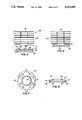
- FIGS. 7 and 8 are top plan and cross sectional views of an adaptor of yet another embodiment of the invention.
- FIG. 9 is a perspective view, partly in cross section, of a heat sink having a continuous helical fin useful with the adaptor of the invention.
- FIG. 10 is a top plan view of a modified heat sink adaptor; and FIG. 11 is a cross sectional view taken on line 11--11 of FIG. 10.
- a heat sink assembly 10 for an electronic device package containing a solid state device such as a microcompressor or the like, comprising an adaptor 12 formed of an electrically insulative material, such as an ABS plastic, having a top wall 14 and opposed side wall 16, 18 depending therefrom.
- Side walls 16, 18 are formed with laterally inwardly extending lips 20, 22 at their respective distal end portions forming a groove with top wall 14 adapted to capture the outer extremities or marginal portions of a solid state device 24.
- Top wall 14 is formed with a centrally disposed threaded bore 26. If desired a stop wall 19 can be provided depending downwardly from the back side of the adaptor to conveniently center the solid state device relative to bore 26. Stop wall 19 is shown with an optional inwardly extending lip 21.
- Heat sink 28 formed of good thermally conductive material such as aluminum, comprises a plurality of thin members 30 extending integrally from a core 32 having a threaded base 34 adapted to be threadingly received in a threaded bore 26.
- Solid state device 24 such as a microprocessor having a gate array
- Solid state device 24 is inserted into adaptor 12 with the outer marginal portions of the housing of device 24, shown in FIG. 1 by dash lines 23, received between lips 20, 22 and top wall 14 and the stop wall 19 limiting the inward motion of device 24 so that threaded bore 26 is aligned with the central portion of device 24.
- Heat sink 28 is then screwed into threaded bore 26 until it bottoms out against the solid state device 24 in intimate thermal coupling therewith.
- the flat bottom surface of base 34 is adapted to be placed on the space formed by planes lying respectively in the top and bottom of the surfaces forming the grooves to ensure a good thermal coupling with a solid state device received therein.
- Threaded bore 34 of the heat sink extends longitudinally a distance preferably slightly longer than the distance between top wall 14 and the top surface of a device 24 placed within the adaptor so that the heat sink can be screwed in until top wall bows slightly biasing the heat sink against solid state device 12.
- the longitudinal length of the thread on the heat sink base can be selected to extend a certain length to limit downward travel of the heat sink in order to prevent excessive forces from being placed on the electronic device package.
- FIG. 1 structure Due to the stress placed on the adaptor by screwing the heat sink against the solid state device, the FIG. 1 structure will maintain a bias of the heat sink against the solid state device, and thus an efficient heat path, even when the solid state device heats up.
- metal can also be used to form adaptor 12 with lips 20, 21 and 22 coating with a layer of suitable electrically insulative material.
- a boss 40 can be formed on the top wall of adaptor 12' to form a longer axial length of threaded bore 26' to facilitate the attachment between the adaptor and the heat sink.
- FIG. 5 Another embodiment, shown in FIG. 5, provides a snap coupling of heat sink 28' to adaptor 12".
- Base 34' has a tapered flange 42 adapted to be forced through bore 26' until the radially extending lip 44 snaps beyond recessed surface 46.
- the vertical height of tapered flange 42 shown as "a” in FIG. 5, may be selected to be slightly more than the distance between recess surface 46 and the lower surface 48 of top wall 14".
- heat sink 28' This will cause the lower surface 50 of heat sink 28' to be disposed in the space where the housing of solid state device 24 would occupy when inserted in the adaptor so that the tapered surface of flange 42 will cam wall 14 to bow it upwardly as solid state device 24 is pushed into the adaptor thereby insuring an efficient thermal coupling even with changes in temperature.
- heat sink 28' is shown formed with a cylindrical base it will be appreciated that it is within the purview of the invention to provide other configurations, if desired such as oblong or rectangular with a corresponding configured flange and aperture in the top wall.
- FIGS. 7 and 8 show another embodiment of the invention in which adaptor 12'" is provided with lips 20', 22' which have tapered surfaces 20.1, 22.1 respectively so that the adaptor can be placed on top of a solid state device 24 and pushed down onto it with surfaces 20.1 and 22.1 acting as cam surfaces forcing side walls 16', 18' to spread apart with the side walls 16', 18' returning to their normal vertical orientation when lips 20', 22' pass beyond the lower edge of solid state device 24 to securely grasp device 24.
- a heat sink such as heat sink 28" shown in FIG. 9
- the grasping force will be increased as top wall 14'" starts to bow upwardly.
- stop wall 14'" is provided with cut out portions 14.1 to enhance development of spring like characteristics to the wall.
- Heat sink 28" of FIG. 9 is similar to heat sink 28 and 28' shown in the previous figures but instead of having a plurality of separate fin members 30, has a single helical fin 30' integrally formed with core 32.
- FIGS. 10 and 11 show a modified heat sink in which spaced apart grooves are formed on two contiguous sides of the adaptor by lips 22.2 and 21.2 which are adapted to be received under spaced marginal portions of device package 24 to firmly grasp the package when a heat sink is inserted in bore 26 and screwed down into engagement with the package.
Abstract
Description
Claims (19)
Priority Applications (13)
| Application Number | Priority Date | Filing Date | Title |
|---|---|---|---|
| US08/026,515 US5313099A (en) | 1993-03-04 | 1993-03-04 | Heat sink assembly for solid state devices |
| US08/097,483 US5397919A (en) | 1993-03-04 | 1993-07-26 | Heat sink assembly for solid state devices |
| DK94908029.5T DK0687383T3 (en) | 1993-03-04 | 1994-02-14 | Heat sink assembly for semiconductor devices |
| DE69410245T DE69410245T2 (en) | 1993-03-04 | 1994-02-14 | RADIATOR ASSEMBLY DEVICE FOR A SEMICONDUCTOR COMPONENT |
| PCT/US1994/001510 WO1994020987A1 (en) | 1993-03-04 | 1994-02-14 | Heat sink assembly for solid state devices |
| DE9421619U DE9421619U1 (en) | 1993-03-04 | 1994-02-14 | Heatsink device for solid-state components |
| AT94908029T ATE166182T1 (en) | 1993-03-04 | 1994-02-14 | RADIATOR MOUNTING DEVICE FOR A SEMICONDUCTOR COMPONENT |
| CA002143105A CA2143105C (en) | 1993-03-04 | 1994-02-14 | Heat sink assembly for solid state devices |
| KR1019950703330A KR100262045B1 (en) | 1993-03-04 | 1994-02-14 | Heat sink assembly for solid state devices |
| AU61374/94A AU673056B2 (en) | 1993-03-04 | 1994-02-14 | Heat sink assembly for solid state devices |
| BR9405732A BR9405732A (en) | 1993-03-04 | 1994-02-14 | Heat sink assembly for solid state devices |
| JP6519989A JP2971578B2 (en) | 1993-03-04 | 1994-02-14 | Heat sink assembly for solid state device |
| EP94908029A EP0687383B1 (en) | 1993-03-04 | 1994-02-14 | Heat sink assembly for solid state devices |
Applications Claiming Priority (1)
| Application Number | Priority Date | Filing Date | Title |
|---|---|---|---|
| US08/026,515 US5313099A (en) | 1993-03-04 | 1993-03-04 | Heat sink assembly for solid state devices |
Related Child Applications (1)
| Application Number | Title | Priority Date | Filing Date |
|---|---|---|---|
| US08/097,483 Continuation-In-Part US5397919A (en) | 1993-03-04 | 1993-07-26 | Heat sink assembly for solid state devices |
Publications (1)
| Publication Number | Publication Date |
|---|---|
| US5313099A true US5313099A (en) | 1994-05-17 |
Family
ID=21832278
Family Applications (1)
| Application Number | Title | Priority Date | Filing Date |
|---|---|---|---|
| US08/026,515 Expired - Lifetime US5313099A (en) | 1993-03-04 | 1993-03-04 | Heat sink assembly for solid state devices |
Country Status (1)
| Country | Link |
|---|---|
| US (1) | US5313099A (en) |
Cited By (82)
| Publication number | Priority date | Publication date | Assignee | Title |
|---|---|---|---|---|
| US5371652A (en) * | 1993-11-15 | 1994-12-06 | Thermalloy, Inc. | Spring clamp assembly with electrically insulating shoe |
| GB2293487A (en) * | 1994-09-21 | 1996-03-27 | Hewlett Packard Co | Attacking heat sinks to integrated circuits |
| US5549155A (en) * | 1995-04-18 | 1996-08-27 | Thermacore, Inc. | Integrated circuit cooling apparatus |
| US5579827A (en) * | 1995-11-13 | 1996-12-03 | Us Micro Lab, Inc. | Heat sink arrangement for central processing unit |
| US5594624A (en) * | 1994-04-05 | 1997-01-14 | Thermalloy, Inc. | Strap spring for heat sink clip assembly |
| US5603374A (en) * | 1996-04-05 | 1997-02-18 | Malico Inc. | Heat sink assembly for an integrated circuit |
| US5637921A (en) * | 1995-04-21 | 1997-06-10 | Sun Microsystems, Inc. | Sub-ambient temperature electronic package |
| US5667870A (en) * | 1995-07-24 | 1997-09-16 | Chip Coolers, Inc. | Plastic article with interrupted interior threads for securing a threaded heat sink to a heat generating member |
| US5687059A (en) * | 1994-09-07 | 1997-11-11 | Hewlett-Packard Co | Mass storage device mounting scheme |
| US5691041A (en) * | 1995-09-29 | 1997-11-25 | International Business Machines Corporation | Socket for semi-permanently connecting a solder ball grid array device using a dendrite interposer |
| US5738531A (en) * | 1996-09-09 | 1998-04-14 | International Business Machines Corporation | Self-alligning low profile socket for connecting ball grid array devices through a dendritic interposer |
| US5754401A (en) * | 1996-02-16 | 1998-05-19 | Sun Microsystems, Inc. | Pressure compliantly protected heatsink for an electronic device |
| US5774335A (en) * | 1997-04-08 | 1998-06-30 | Chip Coolers, Inc. | Heat sink assembly with height adjustable mounting clip |
| US5777259A (en) * | 1994-01-14 | 1998-07-07 | Brush Wellman Inc. | Heat exchanger assembly and method for making the same |
| US5784257A (en) * | 1997-02-21 | 1998-07-21 | Chip Coolers, Inc. | Heatsink assembly with adjustable retaining clip |
| US5815921A (en) * | 1994-01-26 | 1998-10-06 | Sun Microsystems, Inc. | Electronic package cooling system and heat sink with heat transfer assembly |
| US5825622A (en) * | 1997-05-17 | 1998-10-20 | Chip Coolers, Inc. | Heat sink assembly with adjustable mounting clip |
| US5896269A (en) * | 1996-11-27 | 1999-04-20 | Gateway 2000, Inc. | Positive pressure heat sink conduit |
| US5901040A (en) * | 1997-07-30 | 1999-05-04 | Hewlett-Packard Company | Heat sink and Faraday Cage assembly for a semiconductor module and a power converter |
| US5926370A (en) * | 1998-10-29 | 1999-07-20 | Hewlett-Packard Company | Method and apparatus for a modular integrated apparatus for multi-function components |
| US5945736A (en) * | 1998-09-28 | 1999-08-31 | Chip Coolers, Inc. | Heat sink assembly with snap-in cover plate having multiple pressure capability |
| US5968606A (en) * | 1997-06-30 | 1999-10-19 | Ferro Corporation | Screen printable UV curable conductive material composition |
| US6014315A (en) * | 1998-09-08 | 2000-01-11 | Chip Coolers, Inc. | Heat sink assembly with multiple pressure capability |
| US6020424A (en) * | 1997-06-30 | 2000-02-01 | Ferro Corporation | Screen printable thermally curing conductive gel |
| US6021045A (en) * | 1998-10-26 | 2000-02-01 | Chip Coolers, Inc. | Heat sink assembly with threaded collar and multiple pressure capability |
| US6029742A (en) * | 1994-01-26 | 2000-02-29 | Sun Microsystems, Inc. | Heat exchanger for electronic equipment |
| WO2000014469A1 (en) * | 1998-09-07 | 2000-03-16 | Nokia Networks Oy | Heat exchanger, cabinet for telecommunication devices and method of cooling electronic devices |
| US6061235A (en) * | 1998-11-18 | 2000-05-09 | Hewlett-Packard Company | Method and apparatus for a modular integrated apparatus for heat dissipation, processor integration, electrical interface, and electromagnetic interference management |
| US6075699A (en) * | 1999-01-29 | 2000-06-13 | Chip Coolers, Inc. | Heat sink assembly with snap-in legs |
| US6084178A (en) * | 1998-02-27 | 2000-07-04 | Hewlett-Packard Company | Perimeter clamp for mounting and aligning a semiconductor component as part of a field replaceable unit (FRU) |
| EP1072180A1 (en) * | 1998-04-17 | 2001-01-31 | Advanced Interconnections Corporation | Integrated circuit intercoupling component with heat sink |
| US6191945B1 (en) | 1997-07-30 | 2001-02-20 | Hewlett-Packard Company | Cold plate arrangement for cooling processor and companion voltage regulator |
| US6198630B1 (en) | 1999-01-20 | 2001-03-06 | Hewlett-Packard Company | Method and apparatus for electrical and mechanical attachment, and electromagnetic interference and thermal management of high speed, high density VLSI modules |
| US6201697B1 (en) | 1999-02-16 | 2001-03-13 | Chip Coolers, Inc. | Heat sink assembly with cam lock |
| US6252774B1 (en) | 2000-03-28 | 2001-06-26 | Chip Coolers, Inc. | Multi-device heat sink assembly |
| US6293331B1 (en) | 2000-08-11 | 2001-09-25 | Tyco Electronics Logistics Ag | Vibration and shock resistant heat sink assembly |
| US6304451B1 (en) | 1999-12-01 | 2001-10-16 | Tyco Electronics Logistics Ag | Reverse mount heat sink assembly |
| US6343012B1 (en) * | 2000-11-13 | 2002-01-29 | Tyco Electronics Logistis Ag | Heat dissipation device with threaded fan module |
| US6351392B1 (en) * | 1999-10-05 | 2002-02-26 | Ironwood Electronics, Inc, | Offset array adapter |
| US6394820B1 (en) | 1999-10-14 | 2002-05-28 | Ironwood Electronics, Inc. | Packaged device adapter assembly and mounting apparatus |
| US6515360B2 (en) * | 1999-07-28 | 2003-02-04 | Mitsubishi Denki Kabushiki Kaisha | Packaged semiconductor device and manufacturing method thereof |
| US20030037433A1 (en) * | 2001-08-24 | 2003-02-27 | Cheng Chi Lee | Base for heat sink |
| US6533589B1 (en) | 1999-10-14 | 2003-03-18 | Ironwood Electronics, Inc. | Packaged device adapter assembly |
| US20030085024A1 (en) * | 2001-09-28 | 2003-05-08 | Santiago Juan G | Control of electrolysis gases in electroosmotic pump systems |
| US6606251B1 (en) | 2002-02-07 | 2003-08-12 | Cooligy Inc. | Power conditioning module |
| US20030161107A1 (en) * | 2002-02-27 | 2003-08-28 | Spark Electronic S.R.L. | Heat dissipater for integrated circuits |
| US6618251B2 (en) | 2001-10-09 | 2003-09-09 | Fujitsu Limited | Cooling device capable of contacting target with smaller urging force |
| US20030198021A1 (en) * | 2002-04-23 | 2003-10-23 | Freedman Philip D. | Structure with heat dissipating device and method to produce a computer |
| US6661657B1 (en) | 2002-02-14 | 2003-12-09 | Mercury Computer Systems, Inc. | Circuit board assembly for use in a central inlet chassis configuration |
| US6683787B1 (en) | 2002-02-14 | 2004-01-27 | Mercury Computer Systems, Inc. | Circuit board assembly with integrated air plenum chamber using self-aligning heat sinks |
| US6690575B1 (en) | 2002-02-14 | 2004-02-10 | Mercury Computer Systems, Inc. | Digital data processor chassis with flow balanced air intake into multiple circuit board assemblies |
| US6697255B1 (en) | 2002-02-14 | 2004-02-24 | Mercury Computer Systems, Inc. | Circuit board assembly with integrated shaping and control of flow resistance curve |
| US20040089442A1 (en) * | 2001-09-28 | 2004-05-13 | The Board Of Trustees Of The Leland Stanford Junior University | Electroosmotic microchannel cooling system |
| US20040095728A1 (en) * | 2002-11-15 | 2004-05-20 | Celestica International Inc. | System and method for mounting a heat sink |
| US6741470B2 (en) | 2001-06-01 | 2004-05-25 | Intel Corporation | Reusable thermal solution attachment mechanism and methods of using same |
| US6759588B1 (en) | 2002-02-14 | 2004-07-06 | Mercury Computer Systems, Inc. | Circuit board assembly with a combination thermal, shock, vibration, and/or electromagnetic compatibility cover |
| US6781831B1 (en) | 2002-02-14 | 2004-08-24 | Mercury Computer Systems, Inc. | Card-cage with integrated control and shaping of flow resistance curve for multiple plenum chambers |
| US20040242030A1 (en) * | 2003-05-30 | 2004-12-02 | Ironwood Electronics, Inc. | Packaged device adapter assembly with alignment structure and methods regarding same |
| US20040263007A1 (en) * | 2003-05-19 | 2004-12-30 | Wetherill Associates, Inc. | Thermal transfer container for semiconductor component |
| US20040261975A1 (en) * | 2003-06-27 | 2004-12-30 | Intel Corporation | Radial heat sink with helical shaped fins |
| US6879486B1 (en) | 2002-02-14 | 2005-04-12 | Mercury Computer Systems, Inc. | Central inlet circuit board assembly |
| US20050128715A1 (en) * | 2003-12-16 | 2005-06-16 | Rafael - Armament Development Authority Ltd. | Integrated-circuit cooling system |
| US20060198107A1 (en) * | 2005-03-07 | 2006-09-07 | Kaveh Azar | Heat sink assembly |
| US20060215370A1 (en) * | 2005-03-22 | 2006-09-28 | Yi-Cheng Kuo | Fixed pillar with heat loss |
| US20070019386A1 (en) * | 2005-07-24 | 2007-01-25 | Matteo Gravina | Encompassing Heat Sink |
| US7203065B1 (en) * | 2003-11-24 | 2007-04-10 | Ciena Corporation | Heatsink assembly |
| US20070122622A1 (en) * | 2002-04-23 | 2007-05-31 | Freedman Philip D | Electronic module with thermal dissipating surface |
| US20070279842A1 (en) * | 2006-05-30 | 2007-12-06 | Yazaki Corporation | Electrical connection box |
| US20090159254A1 (en) * | 2007-12-19 | 2009-06-25 | Tyco Electronics Corporation | Heat sink assembly and method of fabricating |
| US20090272512A1 (en) * | 2008-05-01 | 2009-11-05 | Acer Incorporated | Liquid cooling heat dissipating device |
| US20090325408A1 (en) * | 2008-06-30 | 2009-12-31 | Marvin Wong | Single Use Connector For Pulse Oximetry Sensors |
| US20110042042A1 (en) * | 2009-08-24 | 2011-02-24 | Kim Jong Man | Radiating package module for exothermic element |
| US8063485B1 (en) | 2008-06-27 | 2011-11-22 | Advanced Thermal Solutions, Inc. | Electronics package with integrated lugs for cooling attachment |
| US8611090B2 (en) | 2010-09-09 | 2013-12-17 | International Business Machines Corporation | Electronic module with laterally-conducting heat distributor layer |
| US8779585B2 (en) | 2011-08-05 | 2014-07-15 | International Business Machines Corporation | Implementing enhanced thermal conductivity in stacked modules |
| US9048565B2 (en) | 2013-06-12 | 2015-06-02 | Ironwood Electronics, Inc. | Adapter apparatus with deflectable element socket contacts |
| US9054659B2 (en) | 2010-07-16 | 2015-06-09 | Emblation Limited | Apparatus and method for thermal interfacing |
| US9263817B2 (en) | 2013-06-12 | 2016-02-16 | Ironwood Electronics, Inc. | Adapter apparatus with suspended conductive elastomer interconnect |
| US9736966B1 (en) * | 2016-02-10 | 2017-08-15 | International Business Machines Corporation | Heat sink with integrated threaded lid |
| US9877404B1 (en) | 2017-01-27 | 2018-01-23 | Ironwood Electronics, Inc. | Adapter apparatus with socket contacts held in openings by holding structures |
| US10306806B2 (en) | 2017-01-12 | 2019-05-28 | Samtec, Inc. | Cage with an attached heatsink |
| US10784183B2 (en) | 2018-11-30 | 2020-09-22 | Infineon Technologies Ag | Semiconductor module with package extension frames |
Citations (15)
| Publication number | Priority date | Publication date | Assignee | Title |
|---|---|---|---|---|
| US2432513A (en) * | 1946-05-24 | 1947-12-16 | Bell Telephone Labor Inc | Ionic discharge device |
| US2916159A (en) * | 1956-06-05 | 1959-12-08 | Thompson Ramo Wooldridge Inc | Mounting clip |
| US2958515A (en) * | 1958-02-03 | 1960-11-01 | Birtcher Corp | Heat dissipating device for electrical components |
| US3033537A (en) * | 1960-03-07 | 1962-05-08 | Pacific Semiconductors Inc | Transistor cooler |
| US3146384A (en) * | 1961-08-11 | 1964-08-25 | Robert A Ruehle | Mounting device for semiconductors |
| US3182114A (en) * | 1963-01-04 | 1965-05-04 | Fan Tron Corp | Rectifier unit with heat dissipator |
| US3229756A (en) * | 1964-01-21 | 1966-01-18 | Laszlo Z Keresztury | Semiconductor heat sink and/or cooler |
| US3417300A (en) * | 1965-12-15 | 1968-12-17 | Texas Instruments Inc | Economy high power package |
| US4481525A (en) * | 1982-08-12 | 1984-11-06 | Anthony D. Calabro | Heat dissipator for integrated circuit chips |
| US4576224A (en) * | 1983-09-21 | 1986-03-18 | Plessey Overseas Limited | Diamond heatsink assemblies |
| US4607685A (en) * | 1984-07-06 | 1986-08-26 | Burroughs Corporation | Heat sink for integrated circuit package |
| US4745456A (en) * | 1986-09-11 | 1988-05-17 | Thermalloy Incorporated | Heat sink clip assembly |
| US4753287A (en) * | 1986-10-24 | 1988-06-28 | Bicc Plc | Circuit board installation |
| US4924352A (en) * | 1987-12-22 | 1990-05-08 | Societe Anonyme Dite: Alcatel Cit | Method and device for cooling an integrated circuit package |
| US5170323A (en) * | 1991-07-16 | 1992-12-08 | United Technologies Corporation | Electrical component clamping and thermal transfer device |
-
1993
- 1993-03-04 US US08/026,515 patent/US5313099A/en not_active Expired - Lifetime
Patent Citations (15)
| Publication number | Priority date | Publication date | Assignee | Title |
|---|---|---|---|---|
| US2432513A (en) * | 1946-05-24 | 1947-12-16 | Bell Telephone Labor Inc | Ionic discharge device |
| US2916159A (en) * | 1956-06-05 | 1959-12-08 | Thompson Ramo Wooldridge Inc | Mounting clip |
| US2958515A (en) * | 1958-02-03 | 1960-11-01 | Birtcher Corp | Heat dissipating device for electrical components |
| US3033537A (en) * | 1960-03-07 | 1962-05-08 | Pacific Semiconductors Inc | Transistor cooler |
| US3146384A (en) * | 1961-08-11 | 1964-08-25 | Robert A Ruehle | Mounting device for semiconductors |
| US3182114A (en) * | 1963-01-04 | 1965-05-04 | Fan Tron Corp | Rectifier unit with heat dissipator |
| US3229756A (en) * | 1964-01-21 | 1966-01-18 | Laszlo Z Keresztury | Semiconductor heat sink and/or cooler |
| US3417300A (en) * | 1965-12-15 | 1968-12-17 | Texas Instruments Inc | Economy high power package |
| US4481525A (en) * | 1982-08-12 | 1984-11-06 | Anthony D. Calabro | Heat dissipator for integrated circuit chips |
| US4576224A (en) * | 1983-09-21 | 1986-03-18 | Plessey Overseas Limited | Diamond heatsink assemblies |
| US4607685A (en) * | 1984-07-06 | 1986-08-26 | Burroughs Corporation | Heat sink for integrated circuit package |
| US4745456A (en) * | 1986-09-11 | 1988-05-17 | Thermalloy Incorporated | Heat sink clip assembly |
| US4753287A (en) * | 1986-10-24 | 1988-06-28 | Bicc Plc | Circuit board installation |
| US4924352A (en) * | 1987-12-22 | 1990-05-08 | Societe Anonyme Dite: Alcatel Cit | Method and device for cooling an integrated circuit package |
| US5170323A (en) * | 1991-07-16 | 1992-12-08 | United Technologies Corporation | Electrical component clamping and thermal transfer device |
Cited By (109)
| Publication number | Priority date | Publication date | Assignee | Title |
|---|---|---|---|---|
| US5371652A (en) * | 1993-11-15 | 1994-12-06 | Thermalloy, Inc. | Spring clamp assembly with electrically insulating shoe |
| US5777259A (en) * | 1994-01-14 | 1998-07-07 | Brush Wellman Inc. | Heat exchanger assembly and method for making the same |
| US5815921A (en) * | 1994-01-26 | 1998-10-06 | Sun Microsystems, Inc. | Electronic package cooling system and heat sink with heat transfer assembly |
| US6029742A (en) * | 1994-01-26 | 2000-02-29 | Sun Microsystems, Inc. | Heat exchanger for electronic equipment |
| US6115253A (en) * | 1994-04-05 | 2000-09-05 | Thermalloy, Inc. | Strap spring for heat sink clip assembly |
| US5594624A (en) * | 1994-04-05 | 1997-01-14 | Thermalloy, Inc. | Strap spring for heat sink clip assembly |
| US5687059A (en) * | 1994-09-07 | 1997-11-11 | Hewlett-Packard Co | Mass storage device mounting scheme |
| US5594623A (en) * | 1994-09-21 | 1997-01-14 | Hewlett-Packard Co | Method and apparatus for attaching a heat sink and a fan to an integrated circuit package |
| GB2293487B (en) * | 1994-09-21 | 1998-08-12 | Hewlett Packard Co | Method and apparatus for attaching a heat sink and a fan to an intergrated circuit package |
| GB2293487A (en) * | 1994-09-21 | 1996-03-27 | Hewlett Packard Co | Attacking heat sinks to integrated circuits |
| US5549155A (en) * | 1995-04-18 | 1996-08-27 | Thermacore, Inc. | Integrated circuit cooling apparatus |
| US5637921A (en) * | 1995-04-21 | 1997-06-10 | Sun Microsystems, Inc. | Sub-ambient temperature electronic package |
| US5667870A (en) * | 1995-07-24 | 1997-09-16 | Chip Coolers, Inc. | Plastic article with interrupted interior threads for securing a threaded heat sink to a heat generating member |
| US5691041A (en) * | 1995-09-29 | 1997-11-25 | International Business Machines Corporation | Socket for semi-permanently connecting a solder ball grid array device using a dendrite interposer |
| US5770891A (en) * | 1995-09-29 | 1998-06-23 | International Business Machines Corporation | Socket for semi-permanently connecting a solder ball grid array device using a dendrite interposer |
| US5579827A (en) * | 1995-11-13 | 1996-12-03 | Us Micro Lab, Inc. | Heat sink arrangement for central processing unit |
| US5754401A (en) * | 1996-02-16 | 1998-05-19 | Sun Microsystems, Inc. | Pressure compliantly protected heatsink for an electronic device |
| US5603374A (en) * | 1996-04-05 | 1997-02-18 | Malico Inc. | Heat sink assembly for an integrated circuit |
| DE19615032A1 (en) * | 1996-04-05 | 1997-10-23 | Malico Inc | Heat sink assembly for integrated circuit e.g CPU |
| US5738531A (en) * | 1996-09-09 | 1998-04-14 | International Business Machines Corporation | Self-alligning low profile socket for connecting ball grid array devices through a dendritic interposer |
| US5896269A (en) * | 1996-11-27 | 1999-04-20 | Gateway 2000, Inc. | Positive pressure heat sink conduit |
| US5784257A (en) * | 1997-02-21 | 1998-07-21 | Chip Coolers, Inc. | Heatsink assembly with adjustable retaining clip |
| US5774335A (en) * | 1997-04-08 | 1998-06-30 | Chip Coolers, Inc. | Heat sink assembly with height adjustable mounting clip |
| US5825622A (en) * | 1997-05-17 | 1998-10-20 | Chip Coolers, Inc. | Heat sink assembly with adjustable mounting clip |
| US6020424A (en) * | 1997-06-30 | 2000-02-01 | Ferro Corporation | Screen printable thermally curing conductive gel |
| US5968606A (en) * | 1997-06-30 | 1999-10-19 | Ferro Corporation | Screen printable UV curable conductive material composition |
| US6204303B1 (en) | 1997-06-30 | 2001-03-20 | Ferro Corporation | Screen printable curable conductive material composition |
| US6191945B1 (en) | 1997-07-30 | 2001-02-20 | Hewlett-Packard Company | Cold plate arrangement for cooling processor and companion voltage regulator |
| US5901040A (en) * | 1997-07-30 | 1999-05-04 | Hewlett-Packard Company | Heat sink and Faraday Cage assembly for a semiconductor module and a power converter |
| US6084178A (en) * | 1998-02-27 | 2000-07-04 | Hewlett-Packard Company | Perimeter clamp for mounting and aligning a semiconductor component as part of a field replaceable unit (FRU) |
| EP1072180A4 (en) * | 1998-04-17 | 2002-05-02 | Advanced Interconnections | Integrated circuit intercoupling component with heat sink |
| EP1072180A1 (en) * | 1998-04-17 | 2001-01-31 | Advanced Interconnections Corporation | Integrated circuit intercoupling component with heat sink |
| WO2000014469A1 (en) * | 1998-09-07 | 2000-03-16 | Nokia Networks Oy | Heat exchanger, cabinet for telecommunication devices and method of cooling electronic devices |
| US6014315A (en) * | 1998-09-08 | 2000-01-11 | Chip Coolers, Inc. | Heat sink assembly with multiple pressure capability |
| US5945736A (en) * | 1998-09-28 | 1999-08-31 | Chip Coolers, Inc. | Heat sink assembly with snap-in cover plate having multiple pressure capability |
| US6021045A (en) * | 1998-10-26 | 2000-02-01 | Chip Coolers, Inc. | Heat sink assembly with threaded collar and multiple pressure capability |
| US5926370A (en) * | 1998-10-29 | 1999-07-20 | Hewlett-Packard Company | Method and apparatus for a modular integrated apparatus for multi-function components |
| US6061235A (en) * | 1998-11-18 | 2000-05-09 | Hewlett-Packard Company | Method and apparatus for a modular integrated apparatus for heat dissipation, processor integration, electrical interface, and electromagnetic interference management |
| US6198630B1 (en) | 1999-01-20 | 2001-03-06 | Hewlett-Packard Company | Method and apparatus for electrical and mechanical attachment, and electromagnetic interference and thermal management of high speed, high density VLSI modules |
| US6075699A (en) * | 1999-01-29 | 2000-06-13 | Chip Coolers, Inc. | Heat sink assembly with snap-in legs |
| US6201697B1 (en) | 1999-02-16 | 2001-03-13 | Chip Coolers, Inc. | Heat sink assembly with cam lock |
| US6515360B2 (en) * | 1999-07-28 | 2003-02-04 | Mitsubishi Denki Kabushiki Kaisha | Packaged semiconductor device and manufacturing method thereof |
| US6351392B1 (en) * | 1999-10-05 | 2002-02-26 | Ironwood Electronics, Inc, | Offset array adapter |
| US6533589B1 (en) | 1999-10-14 | 2003-03-18 | Ironwood Electronics, Inc. | Packaged device adapter assembly |
| US6394820B1 (en) | 1999-10-14 | 2002-05-28 | Ironwood Electronics, Inc. | Packaged device adapter assembly and mounting apparatus |
| US6304451B1 (en) | 1999-12-01 | 2001-10-16 | Tyco Electronics Logistics Ag | Reverse mount heat sink assembly |
| US6252774B1 (en) | 2000-03-28 | 2001-06-26 | Chip Coolers, Inc. | Multi-device heat sink assembly |
| US6293331B1 (en) | 2000-08-11 | 2001-09-25 | Tyco Electronics Logistics Ag | Vibration and shock resistant heat sink assembly |
| US6343012B1 (en) * | 2000-11-13 | 2002-01-29 | Tyco Electronics Logistis Ag | Heat dissipation device with threaded fan module |
| US6741470B2 (en) | 2001-06-01 | 2004-05-25 | Intel Corporation | Reusable thermal solution attachment mechanism and methods of using same |
| US20030037433A1 (en) * | 2001-08-24 | 2003-02-27 | Cheng Chi Lee | Base for heat sink |
| US6864572B2 (en) * | 2001-08-24 | 2005-03-08 | Hon Hai Precision Ind. Co., Ltd. | Base for heat sink |
| US7134486B2 (en) | 2001-09-28 | 2006-11-14 | The Board Of Trustees Of The Leeland Stanford Junior University | Control of electrolysis gases in electroosmotic pump systems |
| US7334630B2 (en) | 2001-09-28 | 2008-02-26 | The Board Of Trustees Of The Leland Stanford Junior University | Closed-loop microchannel cooling system |
| US20050205241A1 (en) * | 2001-09-28 | 2005-09-22 | The Board Of Trustees Of The Leland Stanford Junior University | Closed-loop microchannel cooling system |
| US6942018B2 (en) | 2001-09-28 | 2005-09-13 | The Board Of Trustees Of The Leland Stanford Junior University | Electroosmotic microchannel cooling system |
| US7131486B2 (en) | 2001-09-28 | 2006-11-07 | The Board Of Trustees Of The Leland Stanford Junior Universty | Electroosmotic microchannel cooling system |
| US20030085024A1 (en) * | 2001-09-28 | 2003-05-08 | Santiago Juan G | Control of electrolysis gases in electroosmotic pump systems |
| US6991024B2 (en) | 2001-09-28 | 2006-01-31 | The Board Of Trustees Of The Leland Stanford Junior University | Electroosmotic microchannel cooling system |
| US20040089442A1 (en) * | 2001-09-28 | 2004-05-13 | The Board Of Trustees Of The Leland Stanford Junior University | Electroosmotic microchannel cooling system |
| US6618251B2 (en) | 2001-10-09 | 2003-09-09 | Fujitsu Limited | Cooling device capable of contacting target with smaller urging force |
| US6678168B2 (en) | 2002-02-07 | 2004-01-13 | Cooligy, Inc. | System including power conditioning modules |
| US6606251B1 (en) | 2002-02-07 | 2003-08-12 | Cooligy Inc. | Power conditioning module |
| US6879486B1 (en) | 2002-02-14 | 2005-04-12 | Mercury Computer Systems, Inc. | Central inlet circuit board assembly |
| US6661657B1 (en) | 2002-02-14 | 2003-12-09 | Mercury Computer Systems, Inc. | Circuit board assembly for use in a central inlet chassis configuration |
| US6781831B1 (en) | 2002-02-14 | 2004-08-24 | Mercury Computer Systems, Inc. | Card-cage with integrated control and shaping of flow resistance curve for multiple plenum chambers |
| US6759588B1 (en) | 2002-02-14 | 2004-07-06 | Mercury Computer Systems, Inc. | Circuit board assembly with a combination thermal, shock, vibration, and/or electromagnetic compatibility cover |
| US6697255B1 (en) | 2002-02-14 | 2004-02-24 | Mercury Computer Systems, Inc. | Circuit board assembly with integrated shaping and control of flow resistance curve |
| US6690575B1 (en) | 2002-02-14 | 2004-02-10 | Mercury Computer Systems, Inc. | Digital data processor chassis with flow balanced air intake into multiple circuit board assemblies |
| US6683787B1 (en) | 2002-02-14 | 2004-01-27 | Mercury Computer Systems, Inc. | Circuit board assembly with integrated air plenum chamber using self-aligning heat sinks |
| US6778397B2 (en) | 2002-02-27 | 2004-08-17 | Spark Electronic S.R.L. | Heat dissipater for integrated circuits |
| US20030161107A1 (en) * | 2002-02-27 | 2003-08-28 | Spark Electronic S.R.L. | Heat dissipater for integrated circuits |
| US20070122622A1 (en) * | 2002-04-23 | 2007-05-31 | Freedman Philip D | Electronic module with thermal dissipating surface |
| US20030198021A1 (en) * | 2002-04-23 | 2003-10-23 | Freedman Philip D. | Structure with heat dissipating device and method to produce a computer |
| US7208191B2 (en) | 2002-04-23 | 2007-04-24 | Freedman Philip D | Structure with heat dissipating device and method |
| WO2004047170A1 (en) * | 2002-11-15 | 2004-06-03 | Celestica International Inc. | System and method for mounting a heat sink |
| US6944023B2 (en) | 2002-11-15 | 2005-09-13 | Celestica International Inc. | System and method for mounting a heat sink |
| US20040095728A1 (en) * | 2002-11-15 | 2004-05-20 | Celestica International Inc. | System and method for mounting a heat sink |
| US20040263007A1 (en) * | 2003-05-19 | 2004-12-30 | Wetherill Associates, Inc. | Thermal transfer container for semiconductor component |
| US20080042501A1 (en) * | 2003-05-19 | 2008-02-21 | Robert Malanga | Thermal transfer container for semiconductor component |
| US6877993B2 (en) | 2003-05-30 | 2005-04-12 | Ironwood Electronics, Inc. | Packaged device adapter assembly with alignment structure and methods regarding same |
| US20040242030A1 (en) * | 2003-05-30 | 2004-12-02 | Ironwood Electronics, Inc. | Packaged device adapter assembly with alignment structure and methods regarding same |
| US6886627B2 (en) * | 2003-06-27 | 2005-05-03 | Intel Corporation | Radial heat sink with helical shaped fins |
| US20040261975A1 (en) * | 2003-06-27 | 2004-12-30 | Intel Corporation | Radial heat sink with helical shaped fins |
| US7203065B1 (en) * | 2003-11-24 | 2007-04-10 | Ciena Corporation | Heatsink assembly |
| US20050128715A1 (en) * | 2003-12-16 | 2005-06-16 | Rafael - Armament Development Authority Ltd. | Integrated-circuit cooling system |
| US20060198107A1 (en) * | 2005-03-07 | 2006-09-07 | Kaveh Azar | Heat sink assembly |
| US7567435B2 (en) | 2005-03-07 | 2009-07-28 | Advanced Thermal Solutions, Inc. | Heat sink assembly |
| US7330355B2 (en) * | 2005-03-22 | 2008-02-12 | Via Technologies Inc. | Fixed pillar with heat loss |
| US20060215370A1 (en) * | 2005-03-22 | 2006-09-28 | Yi-Cheng Kuo | Fixed pillar with heat loss |
| US20070019386A1 (en) * | 2005-07-24 | 2007-01-25 | Matteo Gravina | Encompassing Heat Sink |
| US20070279842A1 (en) * | 2006-05-30 | 2007-12-06 | Yazaki Corporation | Electrical connection box |
| US20090159254A1 (en) * | 2007-12-19 | 2009-06-25 | Tyco Electronics Corporation | Heat sink assembly and method of fabricating |
| US20090272512A1 (en) * | 2008-05-01 | 2009-11-05 | Acer Incorporated | Liquid cooling heat dissipating device |
| US8063485B1 (en) | 2008-06-27 | 2011-11-22 | Advanced Thermal Solutions, Inc. | Electronics package with integrated lugs for cooling attachment |
| US20090325408A1 (en) * | 2008-06-30 | 2009-12-31 | Marvin Wong | Single Use Connector For Pulse Oximetry Sensors |
| US20110042042A1 (en) * | 2009-08-24 | 2011-02-24 | Kim Jong Man | Radiating package module for exothermic element |
| US9054659B2 (en) | 2010-07-16 | 2015-06-09 | Emblation Limited | Apparatus and method for thermal interfacing |
| US8611090B2 (en) | 2010-09-09 | 2013-12-17 | International Business Machines Corporation | Electronic module with laterally-conducting heat distributor layer |
| US9301430B2 (en) | 2010-09-09 | 2016-03-29 | International Business Machines Corporation | Electronic module with laterally-conducting heat distributor layer |
| US10004161B2 (en) | 2010-09-09 | 2018-06-19 | International Business Machines Corporation | Electronic module with laterally-conducting heat distributor layer |
| US8779585B2 (en) | 2011-08-05 | 2014-07-15 | International Business Machines Corporation | Implementing enhanced thermal conductivity in stacked modules |
| US9048565B2 (en) | 2013-06-12 | 2015-06-02 | Ironwood Electronics, Inc. | Adapter apparatus with deflectable element socket contacts |
| US9263817B2 (en) | 2013-06-12 | 2016-02-16 | Ironwood Electronics, Inc. | Adapter apparatus with suspended conductive elastomer interconnect |
| US9736966B1 (en) * | 2016-02-10 | 2017-08-15 | International Business Machines Corporation | Heat sink with integrated threaded lid |
| US10002819B2 (en) | 2016-02-10 | 2018-06-19 | International Business Machines Corporation | Heat sink with integrated threaded lid |
| US10306806B2 (en) | 2017-01-12 | 2019-05-28 | Samtec, Inc. | Cage with an attached heatsink |
| US9877404B1 (en) | 2017-01-27 | 2018-01-23 | Ironwood Electronics, Inc. | Adapter apparatus with socket contacts held in openings by holding structures |
| US10784183B2 (en) | 2018-11-30 | 2020-09-22 | Infineon Technologies Ag | Semiconductor module with package extension frames |
Similar Documents
| Publication | Publication Date | Title |
|---|---|---|
| US5313099A (en) | Heat sink assembly for solid state devices | |
| US5397919A (en) | Heat sink assembly for solid state devices | |
| US5784257A (en) | Heatsink assembly with adjustable retaining clip | |
| US5353193A (en) | High power dissipating packages with matched heatspreader heatsink assemblies | |
| US5579827A (en) | Heat sink arrangement for central processing unit | |
| US5019940A (en) | Mounting apparatus for electronic device packages | |
| US4587595A (en) | Heat sink arrangement with clip-on portion | |
| JP3810458B2 (en) | Heat sink assembly and manufacturing method thereof | |
| US4745456A (en) | Heat sink clip assembly | |
| US4712159A (en) | Heat sink clip assembly | |
| US5466970A (en) | Hooked spring clip | |
| US6115253A (en) | Strap spring for heat sink clip assembly | |
| US6246584B1 (en) | Heat sink | |
| US6293331B1 (en) | Vibration and shock resistant heat sink assembly | |
| US6950310B2 (en) | System and method for self-leveling heat sink for multiple height devices | |
| US5581442A (en) | Spring clip for clamping a heat sink module to an electronic module | |
| JPH0329310B2 (en) | ||
| US8125782B2 (en) | Heat sink assembly | |
| US5825622A (en) | Heat sink assembly with adjustable mounting clip | |
| US7817427B2 (en) | Fastener and heat sink assembly having the same | |
| US4961125A (en) | Apparatus and method of attaching an electronic device package and a heat sink to a circuit board | |
| US20100008045A1 (en) | Heat sink | |
| US4494814A (en) | Heat dissipating lead connector for semiconductor packages | |
| SE526963C2 (en) | Heat conductor for heat transfer between different elements as well as a cabinet for electronic components including a heat pipe |
Legal Events
| Date | Code | Title | Description |
|---|---|---|---|
| AS | Assignment |
Owner name: SQUARE HEAD, INC., RHODE ISLAND Free format text: ASSIGNMENT OF ASSIGNORS INTEREST;ASSIGNORS:TATA, PETER D.;RIFE, WILLIAM B.;REEL/FRAME:006790/0415 Effective date: 19931123 |
|
| STCF | Information on status: patent grant |
Free format text: PATENTED CASE |
|
| AS | Assignment |
Owner name: CHIP COOLERS, INC., RHODE ISLAND Free format text: CHANGE OF NAME;ASSIGNOR:SQUARE HEAD, INC.;REEL/FRAME:007815/0482 Effective date: 19951106 |
|
| FPAY | Fee payment |
Year of fee payment: 4 |
|
| FEPP | Fee payment procedure |
Free format text: PAT HLDR NO LONGER CLAIMS SMALL ENT STAT AS INDIV INVENTOR (ORIGINAL EVENT CODE: LSM1); ENTITY STATUS OF PATENT OWNER: LARGE ENTITY |
|
| AS | Assignment |
Owner name: TYCO ELECTRONICS LOGISTICS AG, SWITZERLAND Free format text: ASSIGNMENT OF ASSIGNORS INTEREST;ASSIGNOR:CHIP COOLERS, INC.;REEL/FRAME:011575/0201 Effective date: 20010406 |
|
| FPAY | Fee payment |
Year of fee payment: 8 |
|
| FPAY | Fee payment |
Year of fee payment: 12 |