US5280719A - Measurement of road roughness - Google Patents
Measurement of road roughness Download PDFInfo
- Publication number
- US5280719A US5280719A US07/613,553 US61355391A US5280719A US 5280719 A US5280719 A US 5280719A US 61355391 A US61355391 A US 61355391A US 5280719 A US5280719 A US 5280719A
- Authority
- US
- United States
- Prior art keywords
- emission
- ultrasound
- vehicle
- measuring
- reception
- Prior art date
- Legal status (The legal status is an assumption and is not a legal conclusion. Google has not performed a legal analysis and makes no representation as to the accuracy of the status listed.)
- Expired - Fee Related
Links
- 238000005259 measurement Methods 0.000 title claims abstract description 22
- 238000002604 ultrasonography Methods 0.000 claims abstract description 45
- 238000000034 method Methods 0.000 claims abstract description 17
- 238000002592 echocardiography Methods 0.000 claims abstract 2
- 238000012937 correction Methods 0.000 claims description 5
- 230000003746 surface roughness Effects 0.000 description 2
- 238000001514 detection method Methods 0.000 description 1
- 230000002349 favourable effect Effects 0.000 description 1
- 238000013507 mapping Methods 0.000 description 1
- 230000003287 optical effect Effects 0.000 description 1
- 230000010363 phase shift Effects 0.000 description 1
- 238000012545 processing Methods 0.000 description 1
Images

Classifications
-
- G—PHYSICS
- G01—MEASURING; TESTING
- G01C—MEASURING DISTANCES, LEVELS OR BEARINGS; SURVEYING; NAVIGATION; GYROSCOPIC INSTRUMENTS; PHOTOGRAMMETRY OR VIDEOGRAMMETRY
- G01C7/00—Tracing profiles
- G01C7/02—Tracing profiles of land surfaces
- G01C7/04—Tracing profiles of land surfaces involving a vehicle which moves along the profile to be traced
Definitions
- the present invention relates to a method and an apparatus for measuring roughness along the surface of a traffic area, e.g. a road or an airport runway.
- the invention concerns measuring the longitudinal dimension of the road, i.e. along a "wheel track”, and not transverse to the road (for instance in order to measure the transverse profile of the wheel track).
- U.S. Pat. No. 4,653,316 discloses a vehicle comprising two attached laser devices longitudinally spaced in relation to each other, which devices emit light beams perpendicularly down towards the road surface. The light spots are read by corresponding detectors (focus detection).
- U.S. Pat. No. 4,685,806 discloses a system in which stationary laser sources generate vertical and horizontal laser planes as a reference for a vehicle, which vehicle is equipped with "laser cameras" or the like, i.e. a transverse row of lasers/detectors or possibly ultrasound transducers directed down towards the road surface.
- laser cameras i.e. a transverse row of lasers/detectors or possibly ultrasound transducers directed down towards the road surface.
- a two-dimensional type mapping along the road track is thereby achieved, but the use of additional lasers for defining e.g. a horizontal plane is expensive and time-consuming.
- the present invention utilizes only one single row of ultrasound transducers, which feature involves cost savings in relation to laser devices. Furthermore, the requirement for fixed reference planes is eliminated when the present invention is put into use, and the measurements can be made quickly and reliably.
- this is achieved by adopting a method for measuring surface roughness along a longitudinal dimension of a traffic area, e.g. along a road.
- a measuring apparatus is carried during use by a vehicle or a carriage trailing behind a vehicle, wherein control means (or control), an energizing means (or energizer) and a recording means (or a recorder) for executing the measurements, as well as measuring devices for trailer/vehicle speed and distance tranvelled, are brought along.
- the method is characterized in that during motion there are simultaneously emitted ultrasound waves down toward the surface of the traffic area from a number N>2 of ultrasound transducers being located in a row on the underside of and along a straight bar which is arranged substantially parallel to the road surface on the trailer/vehicle and in a longitudinal direction.
- the ultrasound transducers are mounted an equal distance x between every two successive transducers, and each transducer receives an ultrasound echo from the surface which is due to that transducer's own emission.
- the method is also characterized in that the measurements are constantly repeated during motion in such a manner that a new ultrasound wave emission is made when the trailer/vehicle has advanced a distance nx in relation to the preceding measurement, n being an integer and n ⁇ N-1, so that an overlap with the preceding measurement is achieved.
- the successive measurements made during motion are chained together after their recording by means of a pre-programmed computer to create a continuous elevation profile of the longitudinal dimension of the traffic area.
- the ultrasound transducers are also tested for correct functioning by means of an automatically controlled comparison of measurement results at corresponding positions by overlap measurements.
- the invention also relates to an apparatus for measuring surface roughness along the longitudinal dimension of the traffic area adapted to be placed in the vehicle/trailer, and comprising control means, energizing means and recording means for the measurements, as well as measuring devices for the trailer/vehicle speed and distance travelled.
- the apparatus is characterized by a straight bar arranged in the trailer/vehicle substantially parallel to the road surface and in the longitudinal direction, on the underside of and along which bar are located a number N>2 of ultrasound transducers in a row, with an equal distance x between every two successive transducers, adapted for simultaneous emission during motion of ultrasound waves down toward the surface of said traffic area and capture of the reflected waves, each transducer being adapted to receive only that ultrasound echo which is due to its own emission.
- the equipment also has one further ultrasound transducer arranged on the bar for correction with regard to changes in air pressure, temperature and humidity.
- the equipment is adapted for repeated emission of ultrasound waves during motion in such a manner that a new emission is made from the ultrasound transducers when the trailer/vehicle has advanced a distance nx relative to the preceding measurement, n being an integer and n ⁇ N-1, so that an overlap with the preceding measurement is achieved.
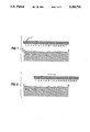
- FIG. 1 schematically illustrates the apparatus according to the present invention at a first position of use
- FIG. 2 illustrates the apparatus of FIG. 1 in a second position of the use
- FIG. 3 schematically illustrates the invention mounted on a vehicle.
- the figure show schematically a substantially horizontal bar I, arranged at a suitable distance about 20 cm above a road surface II.
- the bar has a length of 4 m, and in the disclosed embodiment the bar is equipped with 17 ultrasound transducers directed down toward the road surface.
- the number of transducers and the bar length may of course vary within wide limits.
- the bar I is arranged in a position which is substantially parallel to the road surface and pointing in the movement direction of the vehicle/trailer on which the bar is suspended.
- Ultrasound waves are emitted simultaneously from all transducers perpendicularly down toward the road surface, and the reflections which are detected give rise to signals which are recorded in recording equipment brought along.
- Typical parameters to be measured can be propagation time or phase shift for the received sound waves.
- Apparatus dimensions, distances and wave lengths are suitably selected in such a manner that unwanted influence upon neighboring transducers is minimized or can be removed during signal processing. Only that part of an ultrasound reflection passing substantially perpendicularly up to the emission transducer shall in principle be used in the measurement.
- the propagation velocity of the ultrasound waves is that much higher than the current driving velocities of the vehicle/trailer with the bar that no problems arise due to the fact that the transducers move while the ultrasound waves are in transit between the bar and the road surface.
- the distance between the transducers is 25 cm in the example shown.
- a calculation program may later convert the recorded data in such a manner that maximum sag is computed when the bar "touches" the surface in two ("touching is here only supposed to mean that those two positions in which the shortest distances are measured between bar and road surface, are used as a starting point).
- an energizer for energizing the measuring apparatus As shown in FIG. 3, an energizer for energizing the measuring apparatus, a control for controlling the measuring apparatus and a recorder for recording the measurement made by the measuring apparatus are provided.
- the vehicle or trailer moves all the time towards the right side of the figure.
- a new measurement is made by simultaneous emission of ultrasound waves from all transducers when the bar is located at a distance to the right of the starting position, which is an integral multiple of the distance between two successive transducers.
- the choice of such a measuring interval is made taking into consideration both the wish for high accuracy, which implies a large degree of overlap, i.e. short intervals, and a fast accomplishment of measuring a long road distance, which implies an increased driving speed, requiring longer recording intervals.
- the practical maximum driving speed is in the area 40 km per hour.
- the overlap recording technique described above forms a basis for chaining together successive recordings by means of a computer into a continuous elevation profile of the surface, given in the form of computed "elevations" with a spacing equal to the fixed mutual spacing between the ultrasound transducers.
- the computed elevation values do not represent the real elevation above sea level, but can be used in order to describe irregularities with a wavelength up to 50 m.
- the computed elevation profile forms a basis for calculating different roughness indexes for the road surface.
- the overlap measurements are also used in order to check that all transducers are working correctly.
- the overlapping part of the profile from two successive recordings must be identical (at least after executing corrections for a possible slanting of the whole bar relative to the foregoing recording), and this fact can be used to investigate if all transducers have been calibrated correctly.
Abstract
The present invention relates to a method and apparatus for measuring roughness along a surface (II) of a road or an airport runway in the driving direction. A long bar (I) has a number of ultrasound transducers (1-17) directed down toward the surface (II) of the road. The bar (I) is located e.g. in a carriage trailing behind a vehicle, at a suitable distance (for instance 20 cm) above the road surface (II). During motion, ultrasound pulses are simultaneously emitted form all transducers (1-17) for a subsequent recording of echoes from the road surface (II) with the same transducer, in order to obtain a recording of the distance between the bar and the road surface for each particular transducer. The measurement is repeated when the bar (I) has moved a distance equal to an integral multiple of the distance between two neighboring transducers, in such a manner that a number of the previously measured spots are measured once more, i.e. an overlap technique is used. The measurements are recorded in the vehicle and are data processed at a later time for presentation of e.g. an elevation profile along the completed drive distance measured.
Description
1. Field of the Invention
The present invention relates to a method and an apparatus for measuring roughness along the surface of a traffic area, e.g. a road or an airport runway.
More specifically, the invention concerns measuring the longitudinal dimension of the road, i.e. along a "wheel track", and not transverse to the road (for instance in order to measure the transverse profile of the wheel track).
2. State of the Prior Art
Previously known techniques for measuring roughness or evenness along a road track mainly comprise mechanical sensing techniques. During recent years optical techniques have also been put into use. For example, U.S. Pat. No. 4,653,316 discloses a vehicle comprising two attached laser devices longitudinally spaced in relation to each other, which devices emit light beams perpendicularly down towards the road surface. The light spots are read by corresponding detectors (focus detection).
U.S. Pat. No. 4,685,806 discloses a system in which stationary laser sources generate vertical and horizontal laser planes as a reference for a vehicle, which vehicle is equipped with "laser cameras" or the like, i.e. a transverse row of lasers/detectors or possibly ultrasound transducers directed down towards the road surface. A two-dimensional type mapping along the road track is thereby achieved, but the use of additional lasers for defining e.g. a horizontal plane is expensive and time-consuming.
The present invention utilizes only one single row of ultrasound transducers, which feature involves cost savings in relation to laser devices. Furthermore, the requirement for fixed reference planes is eliminated when the present invention is put into use, and the measurements can be made quickly and reliably.
In accordance with the present invention, this is achieved by adopting a method for measuring surface roughness along a longitudinal dimension of a traffic area, e.g. along a road. In the method a measuring apparatus is carried during use by a vehicle or a carriage trailing behind a vehicle, wherein control means (or control), an energizing means (or energizer) and a recording means (or a recorder) for executing the measurements, as well as measuring devices for trailer/vehicle speed and distance tranvelled, are brought along. The method is characterized in that during motion there are simultaneously emitted ultrasound waves down toward the surface of the traffic area from a number N>2 of ultrasound transducers being located in a row on the underside of and along a straight bar which is arranged substantially parallel to the road surface on the trailer/vehicle and in a longitudinal direction. The ultrasound transducers are mounted an equal distance x between every two successive transducers, and each transducer receives an ultrasound echo from the surface which is due to that transducer's own emission.
Preferably the method is also characterized in that the measurements are constantly repeated during motion in such a manner that a new ultrasound wave emission is made when the trailer/vehicle has advanced a distance nx in relation to the preceding measurement, n being an integer and n<N-1, so that an overlap with the preceding measurement is achieved.
According to another favourable feature of the present invention, the successive measurements made during motion are chained together after their recording by means of a pre-programmed computer to create a continuous elevation profile of the longitudinal dimension of the traffic area.
Preferably the ultrasound transducers are also tested for correct functioning by means of an automatically controlled comparison of measurement results at corresponding positions by overlap measurements.
The invention also relates to an apparatus for measuring surface roughness along the longitudinal dimension of the traffic area adapted to be placed in the vehicle/trailer, and comprising control means, energizing means and recording means for the measurements, as well as measuring devices for the trailer/vehicle speed and distance travelled. The apparatus is characterized by a straight bar arranged in the trailer/vehicle substantially parallel to the road surface and in the longitudinal direction, on the underside of and along which bar are located a number N>2 of ultrasound transducers in a row, with an equal distance x between every two successive transducers, adapted for simultaneous emission during motion of ultrasound waves down toward the surface of said traffic area and capture of the reflected waves, each transducer being adapted to receive only that ultrasound echo which is due to its own emission.
Preferably the equipment also has one further ultrasound transducer arranged on the bar for correction with regard to changes in air pressure, temperature and humidity.
Preferably the equipment is adapted for repeated emission of ultrasound waves during motion in such a manner that a new emission is made from the ultrasound transducers when the trailer/vehicle has advanced a distance nx relative to the preceding measurement, n being an integer and n<N-1, so that an overlap with the preceding measurement is achieved.
The present invention is further described below with reference to the accompanying drawings, wherein:
FIG. 1 schematically illustrates the apparatus according to the present invention at a first position of use;
FIG. 2 illustrates the apparatus of FIG. 1 in a second position of the use; and
FIG. 3 schematically illustrates the invention mounted on a vehicle.
The invention shall now be describe din closer detail, referring to the enclosed drawing figures. The figure show schematically a substantially horizontal bar I, arranged at a suitable distance about 20 cm above a road surface II. As an example, the bar has a length of 4 m, and in the disclosed embodiment the bar is equipped with 17 ultrasound transducers directed down toward the road surface. However, the number of transducers and the bar length may of course vary within wide limits.
As a starting point, it is supposed that the bar I is arranged in a position which is substantially parallel to the road surface and pointing in the movement direction of the vehicle/trailer on which the bar is suspended. Ultrasound waves are emitted simultaneously from all transducers perpendicularly down toward the road surface, and the reflections which are detected give rise to signals which are recorded in recording equipment brought along. Typical parameters to be measured can be propagation time or phase shift for the received sound waves. Apparatus dimensions, distances and wave lengths are suitably selected in such a manner that unwanted influence upon neighboring transducers is minimized or can be removed during signal processing. Only that part of an ultrasound reflection passing substantially perpendicularly up to the emission transducer shall in principle be used in the measurement. The propagation velocity of the ultrasound waves is that much higher than the current driving velocities of the vehicle/trailer with the bar that no problems arise due to the fact that the transducers move while the ultrasound waves are in transit between the bar and the road surface. The distance between the transducers is 25 cm in the example shown. Thus the distance between the road surface and the 17 ultrasound transducers is measured simultaneously for all transducers while the bar is moving. In this way the apparatus can be used as an "automated straight edge". A calculation program may later convert the recorded data in such a manner that maximum sag is computed when the bar "touches" the surface in two ("touching is here only supposed to mean that those two positions in which the shortest distances are measured between bar and road surface, are used as a starting point).
As shown in FIG. 3, an energizer for energizing the measuring apparatus, a control for controlling the measuring apparatus and a recorder for recording the measurement made by the measuring apparatus are provided.
The vehicle or trailer moves all the time towards the right side of the figure. A new measurement is made by simultaneous emission of ultrasound waves from all transducers when the bar is located at a distance to the right of the starting position, which is an integral multiple of the distance between two successive transducers. In the exemplified embodiment the distance from one transducer to the next one is 25 cm, and the interval between two successive measurements has been chosen to be equal to 4×25 cm=1 m. The choice of such a measuring interval is made taking into consideration both the wish for high accuracy, which implies a large degree of overlap, i.e. short intervals, and a fast accomplishment of measuring a long road distance, which implies an increased driving speed, requiring longer recording intervals. In the example shown, with intervals of 1 m, the practical maximum driving speed is in the area 40 km per hour. The overlap recording technique described above forms a basis for chaining together successive recordings by means of a computer into a continuous elevation profile of the surface, given in the form of computed "elevations" with a spacing equal to the fixed mutual spacing between the ultrasound transducers. The computed elevation values do not represent the real elevation above sea level, but can be used in order to describe irregularities with a wavelength up to 50 m. The computed elevation profile forms a basis for calculating different roughness indexes for the road surface.
The overlap measurements are also used in order to check that all transducers are working correctly. The overlapping part of the profile from two successive recordings must be identical (at least after executing corrections for a possible slanting of the whole bar relative to the foregoing recording), and this fact can be used to investigate if all transducers have been calibrated correctly. In the same manner it is also possible to study the accuracy of the measurements and how the accuracy is influenced by the texture of the road surface.
Claims (14)
1. A method for measuring the roughness of a surface, comprising:
providing a measuring apparatus with a vehicle for movement therewith, and further providing a control means for controlling said measuring apparatus, an energizing means for energizing said measuring apparatus and a recording means for recording measurements made by said measuring apparatus, wherein said measuring apparatus comprises a straight bar arranged substantially parallel to the surface and in a longitudinal direction having a number N>3 of ultrasound transducers located in a row therealong and on the underside thereof, said ultrasound transducers being mounted with an equal distance x between every two successive said transducers;
moving the vehicle along the surface such that said bar moves in the longitudinal direction and simultaneously emitting ultrasound waves down toward the surface from said number of ultrasound transducers; and
receiving with each said transducer an ultrasound echo from the surface due that said ultrasound transducer's own ultrasound wave emission.
2. The method of claim 1, and further comprising:
repeating said emission and reception of ultrasound waves during movement of the vehicle each time the vehicle travels a distance nx relative to the location of the preceding said emission and reception, n being an integer preceding said emission and reception, n being an integer and n>N-1, such that the repeated said emission and reception overlaps with the preceding said emission and reception.
3. The method of claim 2, wherein n<N-2.
4. The method of claim 2, wherein successive said emissions and receptions are recorded by said recording means and chained together by a preprogrammed computer into a continuous elevation profile of the longitudinal dimension of the surface.
5. The method of claim 4, wherein said ultrasound transducers are checked for correct functioning by automatically controlled comparison of the results of said emissions and receptions at corresponding overlap positions of said ultrasound transducers.
6. The method of claim 2, wherein said ultrasound transducers are checked for correct functioning by automatically controlled comparison of the results of said emissions and receptions at corresponding overlap positions of said ultrasound transducers.
7. An apparatus for use with a vehicle for measuring the roughness of a surface, comprising:
a straight bar adapted to be arranged substantially parallel to the surface in a longitudinal direction for movement with the vehicle; and
a number N>3 of measuring means for simultaneously emitting ultrasound waves during movement of the vehicle in the longitudinal direction down toward the surface and receiving only their respective reflected ultrasound wave echoes produced by their own emission, said number of measuring means being arranged in a row along the underside of said straight bar with an equal distance x between every two successive said measuring means, and a control means for controlling said number of measuring means, an energizing means for energizing said measuring means and a recording means for recording measurements made by said measuring means in the form of emissions and receptions of said ultrasound waves.
8. The apparatus of claim 7, wherein each said measuring means comprises an ultrasound transducer.
9. The apparatus of claim 8, and further comprising correction means on said bar for providing corrections with regard to changes in air pressure, temperature and humidity.
10. The apparatus of claim 9, wherein said correction means comprises an additional ultrasound transducer.
11. The apparatus of claim 10, wherein said number of measuring means, said control means and said energizing means are adapted for repeating the emission of ultrasound waves during motion of the vehicle such that a new emission and reflection are made from said number of measuring means when said straight bar has advanced a distance nx relative to the point of the preceding simultaneous emission and reception of ultrasound waves, n being an integer and n<N-1, such that the repeated simultaneous emission and reception overlaps with the preceding simultaneous emission and reception.
12. The apparatus of claim 11, wherein n<N-2.
13. The apparatus of claim 7, wherein said number of measuring means, said control means and said energizing means are adapted for repeating the emission of ultrasound waves during motion of the vehicle such that a new emission and reflection are made from said number of measuring means when said straight bar has advanced a distance nx relative to the point of the preceding simultaneous emission and reception of ultrasound waves, n being an integer and n<N-1, such that the repeated simultaneous emission and reception overlaps with the preceding simultaneous emission and reception.
14. The apparatus of claim 13, wherein n<N-2.
Applications Claiming Priority (2)
| Application Number | Priority Date | Filing Date | Title |
|---|---|---|---|
| NO882098A NO169309C (en) | 1988-05-13 | 1988-05-13 | MEASUREMENT OF ROAD SURFACE EQUITY |
| NO882098 | 1988-05-13 |
Publications (1)
| Publication Number | Publication Date |
|---|---|
| US5280719A true US5280719A (en) | 1994-01-25 |
Family
ID=19890884
Family Applications (1)
| Application Number | Title | Priority Date | Filing Date |
|---|---|---|---|
| US07/613,553 Expired - Fee Related US5280719A (en) | 1988-05-13 | 1989-05-11 | Measurement of road roughness |
Country Status (7)
| Country | Link |
|---|---|
| US (1) | US5280719A (en) |
| JP (1) | JPH03505252A (en) |
| DK (1) | DK164956C (en) |
| GB (1) | GB2239316B (en) |
| NO (1) | NO169309C (en) |
| SE (1) | SE470272B (en) |
| WO (1) | WO1989011001A1 (en) |
Cited By (13)
| Publication number | Priority date | Publication date | Assignee | Title |
|---|---|---|---|---|
| US5700955A (en) * | 1996-04-22 | 1997-12-23 | United States Of America As Represented By The Administrator Of The National Aeronautics And Space Administration | Precision thickness variation mapping via one-transducer ultrasonic high resolution profilometry for sample with irregular or rough surface |
| US6161429A (en) * | 1998-10-13 | 2000-12-19 | Paveset America, Llc | Dual path profilograph |
| US6230552B1 (en) * | 1998-05-28 | 2001-05-15 | New Tokyo International Airport Authority | Surface treatment shape evaluation system and surface treatment shape |
| WO2001044754A1 (en) * | 1999-12-17 | 2001-06-21 | Laboratoire Central Des Ponts Et Chaussees | Method for measuring the profile of a road |
| US20050204572A1 (en) * | 2003-03-17 | 2005-09-22 | Schajer Gary S | Surface profile measurement, independent of relative motions |
| US20090076722A1 (en) * | 2007-09-14 | 2009-03-19 | John Darlington | Road profiler and method therefor |
| US7845878B1 (en) | 2002-03-15 | 2010-12-07 | Gomaco Corporation | Smoothness indicator |
| US7850395B1 (en) | 2002-03-15 | 2010-12-14 | GOMACO Corporation a division of Godbersen Smith Construction Co. | Smoothness indicator analysis system |
| US20110259114A1 (en) * | 2009-10-16 | 2011-10-27 | Dynatest International A/S | Triangulation of pavement deflections using more than four sensors |
| US8892367B2 (en) | 2009-10-16 | 2014-11-18 | Dynatest International A/S | Determination of subgrade modulus and stiffness of pavement layers for measurement of bearing capacity under fast moving wheel load |
| CN104406570A (en) * | 2014-12-08 | 2015-03-11 | 鞍钢集团矿业公司 | Portable device and method for measuring vertical fractal characteristics of structural surface |
| US9395180B2 (en) | 2010-02-08 | 2016-07-19 | Fpinnovations | Measurement of the surface shape map of flat and curvy objects, independent of relative motions |
| US11060245B1 (en) | 2005-02-23 | 2021-07-13 | Gomaco Corporation | Method for operating paving train machines |
Citations (1)
| Publication number | Priority date | Publication date | Assignee | Title |
|---|---|---|---|---|
| US4048849A (en) * | 1974-07-22 | 1977-09-20 | Nippon Kokan Kabushiki Kaisha | Method and apparatus for measuring surface flatness of material |
Family Cites Families (4)
| Publication number | Priority date | Publication date | Assignee | Title |
|---|---|---|---|---|
| US4422322A (en) * | 1982-04-27 | 1983-12-27 | Spangler Elson B | Method and system for measurement of road profile |
| SE442675B (en) * | 1984-05-30 | 1986-01-20 | Peter Arnberg | DEVICE FOR SOIL-FREE SEATING OF THE PROTECTION OF TRAFFIC SURFACES |
| JPS614986A (en) * | 1984-06-20 | 1986-01-10 | Nissan Motor Co Ltd | Ultrasonic distance measuring instrument |
| US4653316A (en) * | 1986-03-14 | 1987-03-31 | Kabushiki Kaisha Komatsu Seisakusho | Apparatus mounted on vehicles for detecting road surface conditions |
-
1988
- 1988-05-13 NO NO882098A patent/NO169309C/en unknown
-
1989
- 1989-05-11 WO PCT/NO1989/000046 patent/WO1989011001A1/en unknown
- 1989-05-11 US US07/613,553 patent/US5280719A/en not_active Expired - Fee Related
- 1989-05-11 JP JP1505712A patent/JPH03505252A/en active Pending
-
1990
- 1990-11-07 DK DK266890A patent/DK164956C/en not_active IP Right Cessation
- 1990-11-08 GB GB9024331A patent/GB2239316B/en not_active Expired - Fee Related
- 1990-11-09 SE SE9003575A patent/SE470272B/en not_active IP Right Cessation
Patent Citations (1)
| Publication number | Priority date | Publication date | Assignee | Title |
|---|---|---|---|---|
| US4048849A (en) * | 1974-07-22 | 1977-09-20 | Nippon Kokan Kabushiki Kaisha | Method and apparatus for measuring surface flatness of material |
Cited By (18)
| Publication number | Priority date | Publication date | Assignee | Title |
|---|---|---|---|---|
| US5700955A (en) * | 1996-04-22 | 1997-12-23 | United States Of America As Represented By The Administrator Of The National Aeronautics And Space Administration | Precision thickness variation mapping via one-transducer ultrasonic high resolution profilometry for sample with irregular or rough surface |
| US6230552B1 (en) * | 1998-05-28 | 2001-05-15 | New Tokyo International Airport Authority | Surface treatment shape evaluation system and surface treatment shape |
| US6161429A (en) * | 1998-10-13 | 2000-12-19 | Paveset America, Llc | Dual path profilograph |
| WO2001044754A1 (en) * | 1999-12-17 | 2001-06-21 | Laboratoire Central Des Ponts Et Chaussees | Method for measuring the profile of a road |
| FR2802631A1 (en) * | 1999-12-17 | 2001-06-22 | France Etat Ponts Chaussees | MEASURING THE PROFILE OF A PAVEMENT |
| US6688167B2 (en) | 1999-12-17 | 2004-02-10 | Laboratoire Centrao Des Ponts Et Chaussees | Measuring the profile of a pavement by moving three contactless distance-measuring sensors |
| US7845878B1 (en) | 2002-03-15 | 2010-12-07 | Gomaco Corporation | Smoothness indicator |
| US7850395B1 (en) | 2002-03-15 | 2010-12-14 | GOMACO Corporation a division of Godbersen Smith Construction Co. | Smoothness indicator analysis system |
| US20050204572A1 (en) * | 2003-03-17 | 2005-09-22 | Schajer Gary S | Surface profile measurement, independent of relative motions |
| US7003894B2 (en) * | 2003-03-17 | 2006-02-28 | Forintek Canada Corp. | Surface profile measurement, independent of relative motions |
| US11060245B1 (en) | 2005-02-23 | 2021-07-13 | Gomaco Corporation | Method for operating paving train machines |
| US20090076722A1 (en) * | 2007-09-14 | 2009-03-19 | John Darlington | Road profiler and method therefor |
| US8596116B2 (en) * | 2009-10-16 | 2013-12-03 | Dynatest International A/S | Triangulation of pavement deflections using more than four sensors |
| US8892367B2 (en) | 2009-10-16 | 2014-11-18 | Dynatest International A/S | Determination of subgrade modulus and stiffness of pavement layers for measurement of bearing capacity under fast moving wheel load |
| DK178382B1 (en) * | 2009-10-16 | 2016-01-25 | Dynatest Internat A S | Rolling weight pavement deflection measurement system and method |
| US20110259114A1 (en) * | 2009-10-16 | 2011-10-27 | Dynatest International A/S | Triangulation of pavement deflections using more than four sensors |
| US9395180B2 (en) | 2010-02-08 | 2016-07-19 | Fpinnovations | Measurement of the surface shape map of flat and curvy objects, independent of relative motions |
| CN104406570A (en) * | 2014-12-08 | 2015-03-11 | 鞍钢集团矿业公司 | Portable device and method for measuring vertical fractal characteristics of structural surface |
Also Published As
| Publication number | Publication date |
|---|---|
| GB2239316A (en) | 1991-06-26 |
| NO169309C (en) | 1992-06-03 |
| NO882098L (en) | 1989-11-14 |
| NO882098D0 (en) | 1988-05-13 |
| DK164956C (en) | 1993-02-08 |
| DK164956B (en) | 1992-09-21 |
| DK266890A (en) | 1990-11-07 |
| SE9003575L (en) | 1990-11-09 |
| SE9003575D0 (en) | 1990-11-09 |
| SE470272B (en) | 1993-12-20 |
| WO1989011001A1 (en) | 1989-11-16 |
| GB9024331D0 (en) | 1991-01-23 |
| NO169309B (en) | 1992-02-24 |
| GB2239316B (en) | 1992-07-29 |
| JPH03505252A (en) | 1991-11-14 |
| DK266890D0 (en) | 1990-11-07 |
Similar Documents
| Publication | Publication Date | Title |
|---|---|---|
| EP1023610B1 (en) | Method and device for association of anonymous reflectors to detected angle positions | |
| US5280719A (en) | Measurement of road roughness | |
| US6873570B2 (en) | High resolution bathymetric sonar system and measuring method for measuring the physiognomy of the seabed | |
| US4532617A (en) | System for locating a towed marine object | |
| US6119353A (en) | Method and apparatus for non-contact measuring of the deflection of roads or rails | |
| US4635236A (en) | Submerged marine streamer locator | |
| US4924448A (en) | Bistatic system and method for ocean bottom mapping and surveying | |
| US4446538A (en) | Marine cable location system | |
| US4669067A (en) | Method and apparatus for locating a submerged marine streamer | |
| NZ199066A (en) | Marine seismic streamer location | |
| US20220155767A1 (en) | Autonomous metal-plate inspection apparatus, inspection method, and method for manufacturing metal plate | |
| US3381264A (en) | Submarine topography | |
| US4513401A (en) | Marine cable location system | |
| US4555779A (en) | Submerged marine streamer locator | |
| US4685806A (en) | Laser plane apparatus for measuring characteristics of traffic-bearing surfaces | |
| JPH02122307A (en) | Dynamic control/guide system | |
| Korba | Variable aperture sonar for mobile robots | |
| US2801403A (en) | Measuring railroad tunnels by echo sounding | |
| JPH1062532A (en) | Radar for vehicle | |
| RU2803398C1 (en) | Laser scanning system to determine the parameters of the vehicle in the traffic stream | |
| RU2124180C1 (en) | Method measuring diameter of wheel of rolling stock | |
| RU2736231C1 (en) | Method for determining sound velocity distribution | |
| SU1481698A1 (en) | Device for determining sound velocity in sea sediments | |
| JPS60178373A (en) | Detection of obstacle in moving body | |
| SU1293630A1 (en) | Method of ultrasonic checking of articles |
Legal Events
| Date | Code | Title | Description |
|---|---|---|---|
| AS | Assignment |
Owner name: VEIDIREKTORATET, VEGLABORATORIET, P.O. BOX 6390 ET Free format text: ASSIGNMENT OF ASSIGNORS INTEREST.;ASSIGNOR:NOSS, PER M.;REEL/FRAME:005566/0547 Effective date: 19910107 |
|
| REMI | Maintenance fee reminder mailed | ||
| LAPS | Lapse for failure to pay maintenance fees | ||
| FP | Lapsed due to failure to pay maintenance fee |
Effective date: 19980128 |
|
| STCH | Information on status: patent discontinuation |
Free format text: PATENT EXPIRED DUE TO NONPAYMENT OF MAINTENANCE FEES UNDER 37 CFR 1.362 |