US5259267A - Automatic control device having a multi-element knob - Google Patents
Automatic control device having a multi-element knob Download PDFInfo
- Publication number
- US5259267A US5259267A US07/882,758 US88275892A US5259267A US 5259267 A US5259267 A US 5259267A US 88275892 A US88275892 A US 88275892A US 5259267 A US5259267 A US 5259267A
- Authority
- US
- United States
- Prior art keywords
- knob
- control device
- elements
- manually operable
- reading
- Prior art date
- Legal status (The legal status is an assumption and is not a legal conclusion. Google has not performed a legal analysis and makes no representation as to the accuracy of the status listed.)
- Expired - Fee Related
Links
Images

Classifications
-
- H—ELECTRICITY
- H01—ELECTRIC ELEMENTS
- H01H—ELECTRIC SWITCHES; RELAYS; SELECTORS; EMERGENCY PROTECTIVE DEVICES
- H01H9/00—Details of switching devices, not covered by groups H01H1/00 - H01H7/00
- H01H9/16—Indicators for switching condition, e.g. "on" or "off"
-
- H—ELECTRICITY
- H01—ELECTRIC ELEMENTS
- H01H—ELECTRIC SWITCHES; RELAYS; SELECTORS; EMERGENCY PROTECTIVE DEVICES
- H01H19/00—Switches operated by an operating part which is rotatable about a longitudinal axis thereof and which is acted upon directly by a solid body external to the switch, e.g. by a hand
- H01H19/02—Details
- H01H19/10—Movable parts; Contacts mounted thereon
- H01H19/14—Operating parts, e.g. turn knob
- H01H2019/143—Operating parts, e.g. turn knob having at least two concentric turn knobs
-
- Y—GENERAL TAGGING OF NEW TECHNOLOGICAL DEVELOPMENTS; GENERAL TAGGING OF CROSS-SECTIONAL TECHNOLOGIES SPANNING OVER SEVERAL SECTIONS OF THE IPC; TECHNICAL SUBJECTS COVERED BY FORMER USPC CROSS-REFERENCE ART COLLECTIONS [XRACs] AND DIGESTS
- Y10—TECHNICAL SUBJECTS COVERED BY FORMER USPC
- Y10T—TECHNICAL SUBJECTS COVERED BY FORMER US CLASSIFICATION
- Y10T74/00—Machine element or mechanism
- Y10T74/20—Control lever and linkage systems
- Y10T74/20576—Elements
- Y10T74/20732—Handles
- Y10T74/20834—Hand wheels
- Y10T74/2084—Knob or dial
-
- Y—GENERAL TAGGING OF NEW TECHNOLOGICAL DEVELOPMENTS; GENERAL TAGGING OF CROSS-SECTIONAL TECHNOLOGIES SPANNING OVER SEVERAL SECTIONS OF THE IPC; TECHNICAL SUBJECTS COVERED BY FORMER USPC CROSS-REFERENCE ART COLLECTIONS [XRACs] AND DIGESTS
- Y10—TECHNICAL SUBJECTS COVERED BY FORMER USPC
- Y10T—TECHNICAL SUBJECTS COVERED BY FORMER US CLASSIFICATION
- Y10T74/00—Machine element or mechanism
- Y10T74/20—Control lever and linkage systems
- Y10T74/20576—Elements
- Y10T74/20732—Handles
- Y10T74/20834—Hand wheels
- Y10T74/20864—Handles
Definitions
- a motorized potentiometer has the disadvantage that a driving motor is mechanically coupled with the potentiometer shaft. Therefore, there are two factors determining knob position, namely, the user and the motor. This complicates the additional circuitry and makes the whole product very unreliable and expensive.
- a third known design of automated control is a rotary multipositional switch with no mechanical stop, surrounded by light emitting diodes (LED) With this control, the user turns the switch and the position of the switch is shown by one of the LEDs, which is activated by associated electronics.
- LED light emitting diodes
- one aspect of the present invention resides in a control device having a knob made up of at least two independently rotatable elements, namely, a knob body and a knob cap.
- the device further includes a reader and a driver that have coaxial independently revolving shafts, similar to a double-shafted potentiometer.
- the reader shaft is mechanically coupled to the knob body, while the driver shaft is coupled to the knob cap.
- the shafts are freely movable independently of each other without mechanical interference therebetween, as are the knob cap and knob body.
- the knob body is manually set by an operator, and the knob cap has a position marker which shows the operator the "subjective" position of the knob.
- the reader reads the actual position or movement of the knob body and sends this data to an electronic circuit.
- the circuit puts out corresponding data which is read by the driver, which in turn sets the position of the knob cap.
- the cap and body have no mechanical stop, i.e., they can revolve without restraint. Data outgoing from the reader is processed by the electronic circuit and may differ from data incoming to the driver. This means that the movement of cap does not necessarily have to follow the movement of the knob body. It is only the electronic circuit that determines the cap position setting, and it is only the operator who can move the knob body. This separation of functions of the knob body and the knob cap is essential for the invention.
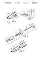
- FIG. 1 is a perspective view of a control device pursuant to the present invention
- FIG. 2 is a section along the line II--II of FIG. 1;
- FIG. 3 is an exploded view of the device of FIG. 1;
- FIG. 4 schematically illustrates the flow of data in the device
- FIGS. 5-6b show various embodiments of the knob and cap
- FIG. 7 is a view similar to FIG. 1, of an additional embodiment of the control device.
- FIGS. 1-4 illustrate a control device having a plastic knob body 2 with an independent cap 1, a reader 3, and a driver 4.
- the reader 3 is an optical encoder having a radially striped disk with an opto-electronic device capable of reading the movement of the disk and its direction.
- the knob body 2 is connected with the reader 3 by a shaft 5, and the disk is attached to the shaft 5 so that the reader 3 reads the movement of the knob body 2.
- the driver 4 is a miniature stepper motor attached to the cap 1 by a shaft 6.
- a circuit 7 is provided between the reader 3 and the driver 4. The circuit 7 receives data from the reader 3 and feeds corresponding data to the driver 4.
- the two element knob having a knob can be used for a wide variety of applications, and can be designed in several ways.
- the cap 1 does not have to be the element moved by the driver 4.
- a ring 8 at the bottom of the knob body 2 can take the place of the cap 1.
- the ring 8 can also be situated at any other point along the knob body 2.
- a marker 8 is provided on the cap 1 or ring 8 to show position of the knob 2.
- FIG. 7 shows an embodiment having an additional knob 10 and an additional cap 11 which are respectively connected to a reader 13 and a driver 12 by independent shafts coaxial with shafts 5, 6.
- Such a multiple arrangement operates on the same principle as the arrangement in FIG. 1.
Abstract
Description
Claims (5)
Priority Applications (1)
| Application Number | Priority Date | Filing Date | Title |
|---|---|---|---|
| US07/882,758 US5259267A (en) | 1990-05-14 | 1992-05-11 | Automatic control device having a multi-element knob |
Applications Claiming Priority (2)
| Application Number | Priority Date | Filing Date | Title |
|---|---|---|---|
| US52428990A | 1990-05-14 | 1990-05-14 | |
| US07/882,758 US5259267A (en) | 1990-05-14 | 1992-05-11 | Automatic control device having a multi-element knob |
Related Parent Applications (1)
| Application Number | Title | Priority Date | Filing Date |
|---|---|---|---|
| US52428990A Continuation-In-Part | 1990-05-14 | 1990-05-14 |
Publications (1)
| Publication Number | Publication Date |
|---|---|
| US5259267A true US5259267A (en) | 1993-11-09 |
Family
ID=27061452
Family Applications (1)
| Application Number | Title | Priority Date | Filing Date |
|---|---|---|---|
| US07/882,758 Expired - Fee Related US5259267A (en) | 1990-05-14 | 1992-05-11 | Automatic control device having a multi-element knob |
Country Status (1)
| Country | Link |
|---|---|
| US (1) | US5259267A (en) |
Cited By (6)
| Publication number | Priority date | Publication date | Assignee | Title |
|---|---|---|---|---|
| EP0957422A2 (en) | 1998-05-14 | 1999-11-17 | Illinois Tool Works Inc. | Control knob using led for backlighting |
| SG83068A1 (en) * | 1994-08-02 | 2001-09-18 | Thomson Multimedia Sa | Improvement to jog and shuttle controls for electronic or electrical devices |
| EP1150242A2 (en) * | 2000-04-27 | 2001-10-31 | Siemens Aktiengesellschaft | Rotation encoder for control inputs |
| US20040070574A1 (en) * | 2002-10-04 | 2004-04-15 | Wylie Brian D. | Method and apparatus for appliance control and status display |
| US20150234418A1 (en) * | 2012-09-14 | 2015-08-20 | Audi Ag | Control device for a functional device of a motor vehicle |
| US20180328471A1 (en) * | 2014-12-09 | 2018-11-15 | Aktiebolaget Skf | Planetary roller screw mechanism |
Citations (6)
| Publication number | Priority date | Publication date | Assignee | Title |
|---|---|---|---|---|
| JPS5776619A (en) * | 1980-10-31 | 1982-05-13 | Pioneer Electronic Corp | Operation knob |
| US4532817A (en) * | 1981-11-06 | 1985-08-06 | Clarion Co., Ltd. | Tuning shaft of pushbutton tuner |
| US4561565A (en) * | 1983-10-28 | 1985-12-31 | Deere & Company | Rate adjustment for chemical meter |
| US4779305A (en) * | 1986-12-15 | 1988-10-25 | Dickey-John Corporation | Positive-positioning knob assembly |
| US4920823A (en) * | 1988-02-05 | 1990-05-01 | U.S. Philips Corporation | Rotary knob for control devices or the like |
| US4947097A (en) * | 1989-06-12 | 1990-08-07 | The Grass Valley Group, Inc. | Automatic switching of motion control with tactile feedback |
-
1992
- 1992-05-11 US US07/882,758 patent/US5259267A/en not_active Expired - Fee Related
Patent Citations (6)
| Publication number | Priority date | Publication date | Assignee | Title |
|---|---|---|---|---|
| JPS5776619A (en) * | 1980-10-31 | 1982-05-13 | Pioneer Electronic Corp | Operation knob |
| US4532817A (en) * | 1981-11-06 | 1985-08-06 | Clarion Co., Ltd. | Tuning shaft of pushbutton tuner |
| US4561565A (en) * | 1983-10-28 | 1985-12-31 | Deere & Company | Rate adjustment for chemical meter |
| US4779305A (en) * | 1986-12-15 | 1988-10-25 | Dickey-John Corporation | Positive-positioning knob assembly |
| US4920823A (en) * | 1988-02-05 | 1990-05-01 | U.S. Philips Corporation | Rotary knob for control devices or the like |
| US4947097A (en) * | 1989-06-12 | 1990-08-07 | The Grass Valley Group, Inc. | Automatic switching of motion control with tactile feedback |
Cited By (9)
| Publication number | Priority date | Publication date | Assignee | Title |
|---|---|---|---|---|
| SG83068A1 (en) * | 1994-08-02 | 2001-09-18 | Thomson Multimedia Sa | Improvement to jog and shuttle controls for electronic or electrical devices |
| EP0957422A2 (en) | 1998-05-14 | 1999-11-17 | Illinois Tool Works Inc. | Control knob using led for backlighting |
| EP1150242A2 (en) * | 2000-04-27 | 2001-10-31 | Siemens Aktiengesellschaft | Rotation encoder for control inputs |
| EP1150242A3 (en) * | 2000-04-27 | 2003-08-20 | Siemens Aktiengesellschaft | Rotation encoder for control inputs |
| US20040070574A1 (en) * | 2002-10-04 | 2004-04-15 | Wylie Brian D. | Method and apparatus for appliance control and status display |
| US7171727B2 (en) | 2002-10-04 | 2007-02-06 | Wolf Appliance Company, Inc. | Method and apparatus for appliance control and status display |
| US20150234418A1 (en) * | 2012-09-14 | 2015-08-20 | Audi Ag | Control device for a functional device of a motor vehicle |
| US20180328471A1 (en) * | 2014-12-09 | 2018-11-15 | Aktiebolaget Skf | Planetary roller screw mechanism |
| US10781900B2 (en) * | 2014-12-09 | 2020-09-22 | Aktiebolaget Skf | Planetary roller screw mechanism |
Similar Documents
| Publication | Publication Date | Title |
|---|---|---|
| JP6506277B2 (en) | Control | |
| US6480752B1 (en) | Final operating element positioning device | |
| RU2300092C2 (en) | Device for sectioning tissue | |
| JPH04268914A (en) | Variable-scale input device | |
| US5259267A (en) | Automatic control device having a multi-element knob | |
| CN108633337B (en) | Light control operation unit with dual-axis encoder | |
| GB2258292A (en) | Automated and manual control knob device. | |
| US6538637B1 (en) | Intrinsic console with positionable programmable multi-function multi-position controllers | |
| US4342271A (en) | Stitch length range indicating arrangement in a multiple pattern sewing machine | |
| US4892312A (en) | Operating device for TV game machine | |
| CA2049281A1 (en) | Automated control device having a multi-element knob | |
| US6025588A (en) | Optical analog potentiometer | |
| US9722716B2 (en) | Rotary control device | |
| US4019449A (en) | Automatic buttonholing sizing device | |
| DE10304985B3 (en) | Manually-operated switch e.g. for control panel of music mixer desk, using touch-control sensors spaced around mantle surface of operating knob | |
| US4908598A (en) | Rotary potentiometer | |
| JPH0714475A (en) | Multidirectional inputting device | |
| US4044327A (en) | Trimming potentiometers with coarse and fine adjustment means | |
| US5156059A (en) | Retractable component mounting plate for a control console | |
| US5352960A (en) | Programmable speed selector for a Reeves drive | |
| JPS5825757Y2 (en) | Rotational drive amount control device | |
| JPH057627Y2 (en) | ||
| JPH0143286Y2 (en) | ||
| ATE211849T1 (en) | CIRCUIT ARRANGEMENT HAND CONTROLLED BY A MOVABLE PART, SUCH AS A BUTTON | |
| JPH01111223A (en) | Mouse device |
Legal Events
| Date | Code | Title | Description |
|---|---|---|---|
| REMI | Maintenance fee reminder mailed | ||
| FEPP | Fee payment procedure |
Free format text: PETITION RELATED TO MAINTENANCE FEES FILED (ORIGINAL EVENT CODE: PMFP); ENTITY STATUS OF PATENT OWNER: SMALL ENTITY |
|
| FP | Lapsed due to failure to pay maintenance fee |
Effective date: 19971112 |
|
| FPAY | Fee payment |
Year of fee payment: 4 |
|
| SULP | Surcharge for late payment | ||
| FEPP | Fee payment procedure |
Free format text: PETITION RELATED TO MAINTENANCE FEES GRANTED (ORIGINAL EVENT CODE: PMFG); ENTITY STATUS OF PATENT OWNER: SMALL ENTITY |
|
| PRDP | Patent reinstated due to the acceptance of a late maintenance fee |
Effective date: 19990709 |
|
| FEPP | Fee payment procedure |
Free format text: PAYOR NUMBER ASSIGNED (ORIGINAL EVENT CODE: ASPN); ENTITY STATUS OF PATENT OWNER: SMALL ENTITY |
|
| FPAY | Fee payment |
Year of fee payment: 8 |
|
| FEPP | Fee payment procedure |
Free format text: PAYER NUMBER DE-ASSIGNED (ORIGINAL EVENT CODE: RMPN); ENTITY STATUS OF PATENT OWNER: SMALL ENTITY Free format text: PAYOR NUMBER ASSIGNED (ORIGINAL EVENT CODE: ASPN); ENTITY STATUS OF PATENT OWNER: SMALL ENTITY |
|
| REMI | Maintenance fee reminder mailed | ||
| LAPS | Lapse for failure to pay maintenance fees | ||
| STCH | Information on status: patent discontinuation |
Free format text: PATENT EXPIRED DUE TO NONPAYMENT OF MAINTENANCE FEES UNDER 37 CFR 1.362 |
|
| FP | Lapsed due to failure to pay maintenance fee |
Effective date: 20051109 |