US5238654A - Syringe drive with lead screw mechanism - Google Patents
Syringe drive with lead screw mechanism Download PDFInfo
- Publication number
- US5238654A US5238654A US07/891,780 US89178092A US5238654A US 5238654 A US5238654 A US 5238654A US 89178092 A US89178092 A US 89178092A US 5238654 A US5238654 A US 5238654A
- Authority
- US
- United States
- Prior art keywords
- nut
- lead screw
- syringe drive
- syringe
- plunger
- Prior art date
- Legal status (The legal status is an assumption and is not a legal conclusion. Google has not performed a legal analysis and makes no representation as to the accuracy of the status listed.)
- Expired - Lifetime
Links
Images


Classifications
-
- G—PHYSICS
- G01—MEASURING; TESTING
- G01N—INVESTIGATING OR ANALYSING MATERIALS BY DETERMINING THEIR CHEMICAL OR PHYSICAL PROPERTIES
- G01N35/00—Automatic analysis not limited to methods or materials provided for in any single one of groups G01N1/00 - G01N33/00; Handling materials therefor
- G01N35/10—Devices for transferring samples or any liquids to, in, or from, the analysis apparatus, e.g. suction devices, injection devices
- G01N35/1095—Devices for transferring samples or any liquids to, in, or from, the analysis apparatus, e.g. suction devices, injection devices for supplying the samples to flow-through analysers
- G01N35/1097—Devices for transferring samples or any liquids to, in, or from, the analysis apparatus, e.g. suction devices, injection devices for supplying the samples to flow-through analysers characterised by the valves
-
- G—PHYSICS
- G01—MEASURING; TESTING
- G01N—INVESTIGATING OR ANALYSING MATERIALS BY DETERMINING THEIR CHEMICAL OR PHYSICAL PROPERTIES
- G01N30/00—Investigating or analysing materials by separation into components using adsorption, absorption or similar phenomena or using ion-exchange, e.g. chromatography or field flow fractionation
- G01N30/02—Column chromatography
- G01N30/26—Conditioning of the fluid carrier; Flow patterns
- G01N30/28—Control of physical parameters of the fluid carrier
- G01N30/32—Control of physical parameters of the fluid carrier of pressure or speed
- G01N2030/326—Control of physical parameters of the fluid carrier of pressure or speed pumps
-
- G—PHYSICS
- G01—MEASURING; TESTING
- G01N—INVESTIGATING OR ANALYSING MATERIALS BY DETERMINING THEIR CHEMICAL OR PHYSICAL PROPERTIES
- G01N30/00—Investigating or analysing materials by separation into components using adsorption, absorption or similar phenomena or using ion-exchange, e.g. chromatography or field flow fractionation
- G01N30/02—Column chromatography
- G01N30/26—Conditioning of the fluid carrier; Flow patterns
- G01N30/38—Flow patterns
- G01N2030/382—Flow patterns flow switching in a single column
- G01N2030/385—Flow patterns flow switching in a single column by switching valves
-
- G—PHYSICS
- G01—MEASURING; TESTING
- G01N—INVESTIGATING OR ANALYSING MATERIALS BY DETERMINING THEIR CHEMICAL OR PHYSICAL PROPERTIES
- G01N30/00—Investigating or analysing materials by separation into components using adsorption, absorption or similar phenomena or using ion-exchange, e.g. chromatography or field flow fractionation
- G01N30/02—Column chromatography
- G01N30/04—Preparation or injection of sample to be analysed
- G01N30/16—Injection
- G01N30/18—Injection using a septum or microsyringe
-
- G—PHYSICS
- G01—MEASURING; TESTING
- G01N—INVESTIGATING OR ANALYSING MATERIALS BY DETERMINING THEIR CHEMICAL OR PHYSICAL PROPERTIES
- G01N30/00—Investigating or analysing materials by separation into components using adsorption, absorption or similar phenomena or using ion-exchange, e.g. chromatography or field flow fractionation
- G01N30/02—Column chromatography
- G01N30/04—Preparation or injection of sample to be analysed
- G01N30/16—Injection
- G01N30/20—Injection using a sampling valve
-
- Y—GENERAL TAGGING OF NEW TECHNOLOGICAL DEVELOPMENTS; GENERAL TAGGING OF CROSS-SECTIONAL TECHNOLOGIES SPANNING OVER SEVERAL SECTIONS OF THE IPC; TECHNICAL SUBJECTS COVERED BY FORMER USPC CROSS-REFERENCE ART COLLECTIONS [XRACs] AND DIGESTS
- Y10—TECHNICAL SUBJECTS COVERED BY FORMER USPC
- Y10S—TECHNICAL SUBJECTS COVERED BY FORMER USPC CROSS-REFERENCE ART COLLECTIONS [XRACs] AND DIGESTS
- Y10S128/00—Surgery
- Y10S128/01—Motorized syringe
-
- Y—GENERAL TAGGING OF NEW TECHNOLOGICAL DEVELOPMENTS; GENERAL TAGGING OF CROSS-SECTIONAL TECHNOLOGIES SPANNING OVER SEVERAL SECTIONS OF THE IPC; TECHNICAL SUBJECTS COVERED BY FORMER USPC CROSS-REFERENCE ART COLLECTIONS [XRACs] AND DIGESTS
- Y10—TECHNICAL SUBJECTS COVERED BY FORMER USPC
- Y10T—TECHNICAL SUBJECTS COVERED BY FORMER US CLASSIFICATION
- Y10T74/00—Machine element or mechanism
- Y10T74/18—Mechanical movements
- Y10T74/18568—Reciprocating or oscillating to or from alternating rotary
- Y10T74/18576—Reciprocating or oscillating to or from alternating rotary including screw and nut
- Y10T74/18648—Carriage surrounding, guided by, and primarily supported by member other than screw [e.g., linear guide, etc.]
Definitions
- This invention relates to liquid sampling techniques and devices for taking accurate and reproducible liquid sample volumes, and in particular to a syringe drive with a lead screw mechanism for use in an autosampler system which itself may be used in conjunction with a liquid chromatograph.
- sample volumes may be in the range of 10-50 ⁇ l, but may range down to as little as 1.0 ⁇ l or less.
- the sampling mechanism With the small sample volumes analyzed, it has become critical that the sampling mechanism not only be accurate in the volume taken, but also produce reproducible results. That is, from one sample to the next, the sampling mechanism must be able to withdraw and deliver the same volume, or whatever volume is preselected, time after time.
- Purge mechanisms operate by purging a sample loop.
- purge mechanisms tended to be uncontrolled. That is, gas pressurization or suction alone has been relied on to move a sample volume from its container into the sample loop.
- such mechanisms may be used with a complete fill loop only, where the sample taken completely filled a predetermined volume in a sample loop.
- Syringe transport mechanisms have also been used to withdraw a sample volume from a container.
- the syringe is physically inserted into the sample container, a predetermined sample volume is drawn into the syringe, and the syringe is then removed from the sample container.
- the syringe containing the sample is then physically moved and connected to a sample injection mechanism for injecting the sample into a chromatography column or other separation device or detector.
- Newer syringe and automated sampler designs have utilized multiport valves so that the sample may be drawn directly into a sample loop by the syringe.
- the use of a syringe to withdraw a sample offers the benefit of a low waste level. Only the small volume of sample needed is withdrawn.
- prior syringe mechanisms have had a number of problems which have affected accuracy and reproducibility.
- the syringe includes a plunger which is mechanically connected to a stepper motor through a lead screw drive mechanism.
- Lead screw mechanisms have not provided perfectly linear motion, due either to slight manufacturing defects such as a bent lead screw or misalignment occurring during assembly or in use. Rather, typically there is a cyclic modulation of the linear displacement of the mechanism.
- the screw drive may turn less than one-quarter of a full rotation.
- Any misalignment of the screw drive with respect to the plunger may introduce significant errors into the sample volume and/or the ability to reproduce the same sample volume repeatedly. This increases the costs of manufacturing and assembling the syringe drive because of the need for strict tolerances to minimize any misalignment.
- the drive mechanism will wear and introduce an additional degree of wobble or misalignment. Even if perfectly aligned initially, the mechanism may become misaligned through movement of equipment and the concomitant bumping and jarring of the mechanism which is inevitable during use. Misalignment also increases stress on the mechanism which may result in excess wear.
- the present invention meets that need by providing a syringe of relatively simple construction which is capable of both accurate and reproducible sample volume withdrawals, including volumes of 1.0 ⁇ l or less.
- the syringe drive mechanism of the present invention is preferably adapted for use in an autosampler in conjunction with a liquid chromatography analysis system. However, it may find use in other sampling systems where accuracy and reproducibility in the handling of small liquid volumes are required.
- the screw is driven and caused to rotate by a motor.
- a stepper motor is preferred because such a motor provides the precise starting and stopping of the rotation of the screw which is needed for accurate sample withdrawals.
- the connecting means for the plunger which mechanically connects the plunger to the rotating lead screw comprises a nut threaded onto the screw, a slider mechanism associated with the nut which also includes means for securing the plunger thereto, means for aligning the slider mechanism for linear movement, and means for permitting lateral movement of the nut.
- the means for aligning the slider mechanism comprises a pair of substantially parallel rails and means for slidably securing the slider to the rails.
- the means for permitting this lateral movement of the nut includes at least one bearing having an annular opening therein for the screw to pass through.
- Preferably a pair of bearings are provided, with each bearing positioned on opposite ends of the nut.
- the bearings include hemispherical inner surfaces adapted to mate with correspondingly-shaped exterior surfaces of the nut to permit lateral movement of the nut.
- means are preferably associated with the nut comprising a tab extending laterally from the nut.
- the slider includes a recess therein for receiving the laterally extending tab from the nut, locking the nut in place and preventing rotation thereof during its linear travel along the lead screw.
- means are associated with the screw for preventing backlash of the screw when rotation is initiated by the motor. These means include a biased spring associated with the opposite end of the screw.
- syringe mechanisms of this general type were directly connected to the slider mechanism and required precise alignment of the drive components (lead screw, traveling nut, and slider) for the operation of the plunger. Assembly of the lead screw and other drive components required precise linear alignment with no lateral misalignment which would cause errors in the volume sampled or lack of reproducibility. Even a small degree of lateral movement occurring during the rotation of the screw, whether due to misalignment of the components or from wear of the mechanism, needed to be avoided. Otherwise, variations in the precise linear movement of the plunger would be introduced.
- the present invention provides a mechanism where the traveling nut is permitted to move freely in all directions except for rotation about the lead screw. Some degree of lateral misalignment of the drive components may be tolerated without that misalignment causing sampling errors. Because of the construction of the bearings between which the nut is positioned, lateral misalignment of the drive screw does not affect the precise linear movement of the slider mechanism, and consequently, the plunger. This provides a mechanism which is less expensive to assemble and align properly, but which has a high degree of accuracy and reproducibility. Further, because of the degree of freedom in the, movement of the traveling nut, less stress is placed on the syringe drive mechanism during operation.
- FIG. 1 is a schematic diagram of a typical liquid sampling apparatus utilizing a syringe mechanism
- FIG. 2 is an isometric view of the syringe drive with lead screw mechanism of the present invention
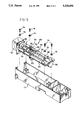
- FIG. 3 is an exploded perspective view of the drive components of the present invention.
- FIG. 4 is an exploded perspective view of the traveling nut and slider mechanism of the present invention.
- FIG. 5 is a perspective view, partially in section, illustrating the assembly of the traveling nut and bearings into the slider mechanism
- FIG. 6 is an exploded perspective view, partially in section, of the anti-backlash spring assembly and lead screw.
- a typical liquid sampling apparatus 10 having a syringe 12.
- Syringe 12 includes a plunger 14 movable by a drive mechanism 16 such as a stepper motor driven lead screw.
- a three-way valve 18 controls whether flush solvent 20 is withdrawn from reservoir 22 by the movement of plunger 14, or whether a sample 24 is withdrawn from vial 26 through needle 28 supported by sample tower 30.
- the six port valve 32 has two positions, namely a "fill” position where the syringe 12 is connected to sample needle 28 via sample loop 34, and an "inject" position where the sample loop 34 is connected to a test column 38 with a fluid source for the sample by means of pump 40.
- test column 38 and pump 40 are not shown, but rather are indicated by the labeled arrows in FIG. 1.
- a computer 42, with associated control lines 44, 46, and 48 controls the entire system by well known methods.
- the operation of six port valve 32, syringe 12, and three-way valve 18 are shown to be controlled by computer 42. Further details concerning the operation of liquid sampling apparatus 10 may be found in Nohl et al, U.S. Pat. No. 4,957,009, issued Sep. 18, 1990, the disclosure of which is hereby incorporated by reference.
- FIGS. 2-6 the details of construction of the syringe drive with lead screw mechanism of the present invention are illustrated.
- syringe 12 and plunger 14 are in communication with three-way valve 18, the position of which determines whether solvent or sample is pulled into the system.
- the drive mechanism, generally indicated at 49, operating plunger 14 includes a threaded lead screw 50, one end of which is driven by a suitable drive means 52 such as a stepper motor. Threaded onto lead screw 50 is a traveling nut 54 which is mounted in a slider mechanism 56.
- Slider mechanism 56 includes extension 60 which extends through an opening 62 in housing 17 Extension 60 includes an annular passage therein through which a thumb screw 64 extends and secures plunger 14 to slider mechanism 56. Linear movement of slider 56 translates directly into a corresponding linear movement of plunger 14.
- Slider 56 is aligned for linear movement along parallel rails 66 and 68. As shown, slider 56 is slidingly secured to rails 66, 68 by suitable means such as C-shaped clips 70 and/or rings 72. The drive mechanism 49 is secured in housing 17 by suitable means such as screws 74 and washers 76.
- traveling nut 54 includes means for permitting lateral movement of the nut within slider mechanism 56.
- theses means include a pair of bearings 80 and 82 which are designed to fit over the opposite ends of nut 54.
- Bearings 80, 82 include annular openings therethrough for the threaded lead screw 50 to pass.
- the bearings have hemispherically-shaped inner surfaces which mate with the correspondingly-shaped ends of nut 54. These bearings permit the nut 54 to wobble or deviate laterally from its position within slider mechanism 56 and accommodate some misalignment or manufacturing defects in lead screw 50.
- nut 54 is prevented from rotating by means of a laterally extending tab 86 which fits into a corresponding recess in extension 60 of slider mechanism 56.
- nut 54 is permitted to move in all directions except for rotation around threaded lead screw 50.
- the slider mechanism 56, nut 54, and bearings 80, 82 may all be molded from a hard plastic material such as Nylon® or Delrin®.
- the nut and slider are of Nylon®, while the bearings are of Delrin®.
- the syringe drive of the present invention also includes means associated with lead screw 50 for preventing backlash of the lead screw when rotation is first initiated by stepper motor 52. Backlash may affect the accuracy and reproducibility of the sample size taken.
- this anti-backlash means 90 includes a bearing 92 and a bias spring 94 which are positioned within housing 96. Bearing 92 reduces friction and permits free rotation of lead screw 50 within the drive mechanism. The biased spring 94 eliminates any play in the rotation of the lead screw by stepper motor 52.
Abstract
Description
Claims (18)
Priority Applications (1)
| Application Number | Priority Date | Filing Date | Title |
|---|---|---|---|
| US07/891,780 US5238654A (en) | 1992-06-01 | 1992-06-01 | Syringe drive with lead screw mechanism |
Applications Claiming Priority (1)
| Application Number | Priority Date | Filing Date | Title |
|---|---|---|---|
| US07/891,780 US5238654A (en) | 1992-06-01 | 1992-06-01 | Syringe drive with lead screw mechanism |
Publications (1)
| Publication Number | Publication Date |
|---|---|
| US5238654A true US5238654A (en) | 1993-08-24 |
Family
ID=25398811
Family Applications (1)
| Application Number | Title | Priority Date | Filing Date |
|---|---|---|---|
| US07/891,780 Expired - Lifetime US5238654A (en) | 1992-06-01 | 1992-06-01 | Syringe drive with lead screw mechanism |
Country Status (1)
| Country | Link |
|---|---|
| US (1) | US5238654A (en) |
Cited By (28)
| Publication number | Priority date | Publication date | Assignee | Title |
|---|---|---|---|---|
| EP0829715A2 (en) * | 1996-08-15 | 1998-03-18 | Kyoto Daiichi Kagaku Co., Ltd. | Method and apparatus for performing liquid chromatography |
| US6110149A (en) * | 1996-09-13 | 2000-08-29 | Novo Nordisk A/S | Syringe |
| US6142447A (en) * | 1996-11-26 | 2000-11-07 | Lohr Industries | Translation block with disengaging nut for screw-mounted lifting mechanism |
| US6475188B1 (en) * | 1999-05-20 | 2002-11-05 | Anthony David Baxter | Bilateral microinjector pump for freely moving animals in an operant chamber |
| US20020183702A1 (en) * | 1999-11-29 | 2002-12-05 | Henley Alan Wayne | Wound treatment apparatus |
| US20040172512A1 (en) * | 2003-02-28 | 2004-09-02 | Masashi Nakanishi | Method, apparatus, and computer readable medium for managing back-up |
| US20040249353A1 (en) * | 1999-11-29 | 2004-12-09 | Risks James R. | Wound treatment apparatus |
| US20070295113A1 (en) * | 2004-06-14 | 2007-12-27 | Parker-Hannifin Corporation | Robotic Handling System and Method with Independently Operable Detachable Tools |
| US20080152515A1 (en) * | 2006-12-21 | 2008-06-26 | Karg Jeffrey A | Reciprocating antirotation pump |
| US20080156117A1 (en) * | 2005-01-28 | 2008-07-03 | Parker-Hannifin Corporation | Sampling Probe, Gripper and Interface For Laboratory Sample Management Systems |
| US20080314412A1 (en) * | 2005-12-05 | 2008-12-25 | Grippo Paul M | Self-Cleaning Injection Port for Analytical Applications |
| US20090032065A1 (en) * | 2005-12-08 | 2009-02-05 | Bantz Daniel L | Syringe wash station for analytical applications |
| US20090158862A1 (en) * | 2006-01-27 | 2009-06-25 | Parker Hannifin Corporation | Sampling probe, gripper and interface for laboratory sample management systems |
| US7678090B2 (en) | 1999-11-29 | 2010-03-16 | Risk Jr James R | Wound treatment apparatus |
| US7723560B2 (en) | 2001-12-26 | 2010-05-25 | Lockwood Jeffrey S | Wound vacuum therapy dressing kit |
| US7794438B2 (en) | 1998-08-07 | 2010-09-14 | Alan Wayne Henley | Wound treatment apparatus |
| US7867206B2 (en) | 2000-11-29 | 2011-01-11 | Kci Licensing, Inc. | Vacuum therapy and cleansing dressing for wounds |
| US7896864B2 (en) | 2001-12-26 | 2011-03-01 | Lockwood Jeffrey S | Vented vacuum bandage with irrigation for wound healing and method |
| US7896856B2 (en) | 2002-08-21 | 2011-03-01 | Robert Petrosenko | Wound packing for preventing wound closure |
| US7910791B2 (en) | 2000-05-22 | 2011-03-22 | Coffey Arthur C | Combination SIS and vacuum bandage and method |
| US7927318B2 (en) | 2001-10-11 | 2011-04-19 | Risk Jr James Robert | Waste container for negative pressure therapy |
| US7985216B2 (en) | 2004-03-16 | 2011-07-26 | Dali Medical Devices Ltd. | Medicinal container engagement and automatic needle device |
| US7988680B2 (en) | 2000-11-29 | 2011-08-02 | Kci Medical Resources | Vacuum therapy and cleansing dressing for wounds |
| US8168848B2 (en) | 2002-04-10 | 2012-05-01 | KCI Medical Resources, Inc. | Access openings in vacuum bandage |
| US8350116B2 (en) | 2001-12-26 | 2013-01-08 | Kci Medical Resources | Vacuum bandage packing |
| US8376998B2 (en) | 2003-09-17 | 2013-02-19 | Elcam Medical Agricultural Cooperative Association Ltd. | Automatic injection device |
| US10583228B2 (en) | 2015-07-28 | 2020-03-10 | J&M Shuler Medical, Inc. | Sub-atmospheric wound therapy systems and methods |
| US11160917B2 (en) | 2020-01-22 | 2021-11-02 | J&M Shuler Medical Inc. | Negative pressure wound therapy barrier |
Citations (8)
| Publication number | Priority date | Publication date | Assignee | Title |
|---|---|---|---|---|
| US4475666A (en) * | 1981-08-31 | 1984-10-09 | American Hospital Supply Corporation | Automated liquid dispenser control |
| US4476999A (en) * | 1981-08-31 | 1984-10-16 | American Hospital Supply Corporation | Automated liquid dispenser |
| US4528161A (en) * | 1981-08-31 | 1985-07-09 | American Hospital Supply Corp. | Probe for automated liquid dispenser |
| US4528158A (en) * | 1982-06-14 | 1985-07-09 | Baird Corporation | Automatic sampling system |
| US4544369A (en) * | 1983-11-22 | 1985-10-01 | C. R. Bard, Inc. | Battery operated miniature syringe infusion pump |
| US4622457A (en) * | 1981-03-09 | 1986-11-11 | Spectra-Physics, Inc. | Autosampler mechanism |
| US4957009A (en) * | 1988-09-23 | 1990-09-18 | Spectra-Physics, Inc. | Pushloop liquid sampling method |
| US5101679A (en) * | 1990-01-08 | 1992-04-07 | Ivac Corporation | Screw drive engagement/disengagement and decoupling mechanism |
-
1992
- 1992-06-01 US US07/891,780 patent/US5238654A/en not_active Expired - Lifetime
Patent Citations (8)
| Publication number | Priority date | Publication date | Assignee | Title |
|---|---|---|---|---|
| US4622457A (en) * | 1981-03-09 | 1986-11-11 | Spectra-Physics, Inc. | Autosampler mechanism |
| US4475666A (en) * | 1981-08-31 | 1984-10-09 | American Hospital Supply Corporation | Automated liquid dispenser control |
| US4476999A (en) * | 1981-08-31 | 1984-10-16 | American Hospital Supply Corporation | Automated liquid dispenser |
| US4528161A (en) * | 1981-08-31 | 1985-07-09 | American Hospital Supply Corp. | Probe for automated liquid dispenser |
| US4528158A (en) * | 1982-06-14 | 1985-07-09 | Baird Corporation | Automatic sampling system |
| US4544369A (en) * | 1983-11-22 | 1985-10-01 | C. R. Bard, Inc. | Battery operated miniature syringe infusion pump |
| US4957009A (en) * | 1988-09-23 | 1990-09-18 | Spectra-Physics, Inc. | Pushloop liquid sampling method |
| US5101679A (en) * | 1990-01-08 | 1992-04-07 | Ivac Corporation | Screw drive engagement/disengagement and decoupling mechanism |
Cited By (42)
| Publication number | Priority date | Publication date | Assignee | Title |
|---|---|---|---|---|
| EP0829715A3 (en) * | 1996-08-15 | 1999-12-22 | Kyoto Daiichi Kagaku Co., Ltd. | Method and apparatus for performing liquid chromatography |
| EP0829715A2 (en) * | 1996-08-15 | 1998-03-18 | Kyoto Daiichi Kagaku Co., Ltd. | Method and apparatus for performing liquid chromatography |
| US6110149A (en) * | 1996-09-13 | 2000-08-29 | Novo Nordisk A/S | Syringe |
| US6142447A (en) * | 1996-11-26 | 2000-11-07 | Lohr Industries | Translation block with disengaging nut for screw-mounted lifting mechanism |
| US7794438B2 (en) | 1998-08-07 | 2010-09-14 | Alan Wayne Henley | Wound treatment apparatus |
| US8540687B2 (en) | 1998-08-07 | 2013-09-24 | Kci Licensing, Inc. | Wound treatment apparatus |
| US6475188B1 (en) * | 1999-05-20 | 2002-11-05 | Anthony David Baxter | Bilateral microinjector pump for freely moving animals in an operant chamber |
| US8021348B2 (en) | 1999-11-29 | 2011-09-20 | Kci Medical Resources | Wound treatment apparatus |
| US20040249353A1 (en) * | 1999-11-29 | 2004-12-09 | Risks James R. | Wound treatment apparatus |
| US6800074B2 (en) * | 1999-11-29 | 2004-10-05 | Hill-Rom Services, Inc. | Wound treatment apparatus |
| US7678090B2 (en) | 1999-11-29 | 2010-03-16 | Risk Jr James R | Wound treatment apparatus |
| US7763000B2 (en) | 1999-11-29 | 2010-07-27 | Risk Jr James R | Wound treatment apparatus having a display |
| US20020183702A1 (en) * | 1999-11-29 | 2002-12-05 | Henley Alan Wayne | Wound treatment apparatus |
| US8747887B2 (en) | 2000-05-22 | 2014-06-10 | Kci Medical Resources | Combination SIS and vacuum bandage and method |
| US7910791B2 (en) | 2000-05-22 | 2011-03-22 | Coffey Arthur C | Combination SIS and vacuum bandage and method |
| US10357404B2 (en) | 2000-11-29 | 2019-07-23 | Kci Medical Resources Unlimited Company | Vacuum therapy and cleansing dressing for wounds |
| US7988680B2 (en) | 2000-11-29 | 2011-08-02 | Kci Medical Resources | Vacuum therapy and cleansing dressing for wounds |
| US8246592B2 (en) | 2000-11-29 | 2012-08-21 | Kci Medical Resources | Vacuum therapy and cleansing dressing for wounds |
| US7867206B2 (en) | 2000-11-29 | 2011-01-11 | Kci Licensing, Inc. | Vacuum therapy and cleansing dressing for wounds |
| US7927318B2 (en) | 2001-10-11 | 2011-04-19 | Risk Jr James Robert | Waste container for negative pressure therapy |
| US7896864B2 (en) | 2001-12-26 | 2011-03-01 | Lockwood Jeffrey S | Vented vacuum bandage with irrigation for wound healing and method |
| US7723560B2 (en) | 2001-12-26 | 2010-05-25 | Lockwood Jeffrey S | Wound vacuum therapy dressing kit |
| US8350116B2 (en) | 2001-12-26 | 2013-01-08 | Kci Medical Resources | Vacuum bandage packing |
| US8168848B2 (en) | 2002-04-10 | 2012-05-01 | KCI Medical Resources, Inc. | Access openings in vacuum bandage |
| US7896856B2 (en) | 2002-08-21 | 2011-03-01 | Robert Petrosenko | Wound packing for preventing wound closure |
| US20040172512A1 (en) * | 2003-02-28 | 2004-09-02 | Masashi Nakanishi | Method, apparatus, and computer readable medium for managing back-up |
| EP2650033A2 (en) | 2003-09-17 | 2013-10-16 | Elcam Medical Agricultural Cooperative Association Ltd. | Automatic injection device |
| US11623051B2 (en) | 2003-09-17 | 2023-04-11 | E3D Agricultural Cooperative Association Ltd. | Automatic injection device |
| US8376998B2 (en) | 2003-09-17 | 2013-02-19 | Elcam Medical Agricultural Cooperative Association Ltd. | Automatic injection device |
| US7985216B2 (en) | 2004-03-16 | 2011-07-26 | Dali Medical Devices Ltd. | Medicinal container engagement and automatic needle device |
| US20070295113A1 (en) * | 2004-06-14 | 2007-12-27 | Parker-Hannifin Corporation | Robotic Handling System and Method with Independently Operable Detachable Tools |
| US8187535B2 (en) | 2004-06-14 | 2012-05-29 | Parker-Hannifin Corporation | Robotic handling system and method with independently operable detachable tools |
| US8057756B2 (en) | 2005-01-28 | 2011-11-15 | Parker-Hannifin Corporation | Sampling probe, gripper and interface for laboratory sample management systems |
| US20080156117A1 (en) * | 2005-01-28 | 2008-07-03 | Parker-Hannifin Corporation | Sampling Probe, Gripper and Interface For Laboratory Sample Management Systems |
| US20080314412A1 (en) * | 2005-12-05 | 2008-12-25 | Grippo Paul M | Self-Cleaning Injection Port for Analytical Applications |
| US20090032065A1 (en) * | 2005-12-08 | 2009-02-05 | Bantz Daniel L | Syringe wash station for analytical applications |
| US8192698B2 (en) | 2006-01-27 | 2012-06-05 | Parker-Hannifin Corporation | Sampling probe, gripper and interface for laboratory sample management systems |
| US20090158862A1 (en) * | 2006-01-27 | 2009-06-25 | Parker Hannifin Corporation | Sampling probe, gripper and interface for laboratory sample management systems |
| US20080152515A1 (en) * | 2006-12-21 | 2008-06-26 | Karg Jeffrey A | Reciprocating antirotation pump |
| US10583228B2 (en) | 2015-07-28 | 2020-03-10 | J&M Shuler Medical, Inc. | Sub-atmospheric wound therapy systems and methods |
| US11160917B2 (en) | 2020-01-22 | 2021-11-02 | J&M Shuler Medical Inc. | Negative pressure wound therapy barrier |
| US11766514B2 (en) | 2020-01-22 | 2023-09-26 | J&M Shuler Medical Inc. | Negative pressure wound therapy barrier |
Similar Documents
| Publication | Publication Date | Title |
|---|---|---|
| US5238654A (en) | Syringe drive with lead screw mechanism | |
| US5814742A (en) | Fully automated micro-autosampler for micro, capillary and nano high performance liquid chromatography | |
| EP0327658B1 (en) | Sample injector for a liquid chromatograph | |
| US6168759B1 (en) | Analyzer transport device | |
| US5105322A (en) | Transverse positioner for read/write head | |
| US5286652A (en) | Automated sample input module | |
| US4478095A (en) | Autosampler mechanism | |
| US5032151A (en) | System and method for automated cool on-column injection with column diameters less than 530 μm | |
| US3508442A (en) | Automatic liquid sampler for chromatography | |
| US20160245730A1 (en) | Autosampler and gas chromatography system and method including same | |
| US4944781A (en) | Gas chromatograph/autosampler coupling assembly | |
| Steiner et al. | HPLC autosamplers: Perspectives, principles, and practices | |
| CN208568697U (en) | A kind of automatic sampling apparatus for high performance liquid chromatograph | |
| CA1080173A (en) | Fluid proportioning apparatus | |
| US4957009A (en) | Pushloop liquid sampling method | |
| WO2005011832A2 (en) | A simultaneous multi-colum liquid chromatograph for direct sampling of an array of liquid samples | |
| US4577515A (en) | Sampling valve for use in high-speed liquid chromatography | |
| US3550453A (en) | Automatic liquid sampler | |
| US11879875B2 (en) | Sample manager, system and method | |
| JPH04225159A (en) | Injector-plunger returning device | |
| GB2290283A (en) | Rotary injection valve | |
| US3529475A (en) | Automatic fluid sampling system | |
| US4346610A (en) | Device for introducing micro amount of sample into an analyzing apparatus | |
| US4352300A (en) | Combined linear and circular drive mechanism | |
| GB2112519A (en) | Hydrodynamic sample introduction system |
Legal Events
| Date | Code | Title | Description |
|---|---|---|---|
| AS | Assignment |
Owner name: SPECTRA-PHYSICS ANALYTICAL, INC., CALIFORNIA Free format text: ASSIGNMENT OF ASSIGNORS INTEREST.;ASSIGNORS:NOHL, ANDRE;MCCALL, THOMAS J. JR.;REEL/FRAME:006308/0623;SIGNING DATES FROM 19920505 TO 19920629 |
|
| AS | Assignment |
Owner name: THERMO SEPARATION PRODUCTS (CALIFORNIA) INC., CALI Free format text: CHANGE OF NAME;ASSIGNOR:SPECTRA-PHYSICS ANALYTICAL, INC.;REEL/FRAME:006573/0613 Effective date: 19930226 |
|
| STCF | Information on status: patent grant |
Free format text: PATENTED CASE |
|
| AS | Assignment |
Owner name: THERMO SEPARATION PRODUCTS INC., CALIFORNIA Free format text: MERGER;ASSIGNORS:THERMO SEPARATION PRODUCTS (CALIFORNIA) INC.;THERMO SEPARATION PRODUCTS (FLORIDA) INC.;REEL/FRAME:006997/0733 Effective date: 19931223 |
|
| FEPP | Fee payment procedure |
Free format text: PAYOR NUMBER ASSIGNED (ORIGINAL EVENT CODE: ASPN); ENTITY STATUS OF PATENT OWNER: LARGE ENTITY |
|
| FPAY | Fee payment |
Year of fee payment: 4 |
|
| FPAY | Fee payment |
Year of fee payment: 8 |
|
| FPAY | Fee payment |
Year of fee payment: 12 |