US5233830A - Exhaust gas purification system for an internal combustion engine - Google Patents
Exhaust gas purification system for an internal combustion engine Download PDFInfo
- Publication number
- US5233830A US5233830A US07/709,000 US70900091A US5233830A US 5233830 A US5233830 A US 5233830A US 70900091 A US70900091 A US 70900091A US 5233830 A US5233830 A US 5233830A
- Authority
- US
- United States
- Prior art keywords
- catalyst
- passage
- exhaust gas
- engine
- flow
- Prior art date
- Legal status (The legal status is an assumption and is not a legal conclusion. Google has not performed a legal analysis and makes no representation as to the accuracy of the status listed.)
- Expired - Fee Related
Links
Images


Classifications
-
- F—MECHANICAL ENGINEERING; LIGHTING; HEATING; WEAPONS; BLASTING
- F01—MACHINES OR ENGINES IN GENERAL; ENGINE PLANTS IN GENERAL; STEAM ENGINES
- F01N—GAS-FLOW SILENCERS OR EXHAUST APPARATUS FOR MACHINES OR ENGINES IN GENERAL; GAS-FLOW SILENCERS OR EXHAUST APPARATUS FOR INTERNAL COMBUSTION ENGINES
- F01N3/00—Exhaust or silencing apparatus having means for purifying, rendering innocuous, or otherwise treating exhaust
- F01N3/08—Exhaust or silencing apparatus having means for purifying, rendering innocuous, or otherwise treating exhaust for rendering innocuous
- F01N3/10—Exhaust or silencing apparatus having means for purifying, rendering innocuous, or otherwise treating exhaust for rendering innocuous by thermal or catalytic conversion of noxious components of exhaust
- F01N3/18—Exhaust or silencing apparatus having means for purifying, rendering innocuous, or otherwise treating exhaust for rendering innocuous by thermal or catalytic conversion of noxious components of exhaust characterised by methods of operation; Control
- F01N3/22—Control of additional air supply only, e.g. using by-passes or variable air pump drives
-
- F—MECHANICAL ENGINEERING; LIGHTING; HEATING; WEAPONS; BLASTING
- F01—MACHINES OR ENGINES IN GENERAL; ENGINE PLANTS IN GENERAL; STEAM ENGINES
- F01N—GAS-FLOW SILENCERS OR EXHAUST APPARATUS FOR MACHINES OR ENGINES IN GENERAL; GAS-FLOW SILENCERS OR EXHAUST APPARATUS FOR INTERNAL COMBUSTION ENGINES
- F01N13/00—Exhaust or silencing apparatus characterised by constructional features ; Exhaust or silencing apparatus, or parts thereof, having pertinent characteristics not provided for in, or of interest apart from, groups F01N1/00 - F01N5/00, F01N9/00, F01N11/00
- F01N13/009—Exhaust or silencing apparatus characterised by constructional features ; Exhaust or silencing apparatus, or parts thereof, having pertinent characteristics not provided for in, or of interest apart from, groups F01N1/00 - F01N5/00, F01N9/00, F01N11/00 having two or more separate purifying devices arranged in series
- F01N13/0097—Exhaust or silencing apparatus characterised by constructional features ; Exhaust or silencing apparatus, or parts thereof, having pertinent characteristics not provided for in, or of interest apart from, groups F01N1/00 - F01N5/00, F01N9/00, F01N11/00 having two or more separate purifying devices arranged in series the purifying devices are arranged in a single housing
-
- F—MECHANICAL ENGINEERING; LIGHTING; HEATING; WEAPONS; BLASTING
- F01—MACHINES OR ENGINES IN GENERAL; ENGINE PLANTS IN GENERAL; STEAM ENGINES
- F01N—GAS-FLOW SILENCERS OR EXHAUST APPARATUS FOR MACHINES OR ENGINES IN GENERAL; GAS-FLOW SILENCERS OR EXHAUST APPARATUS FOR INTERNAL COMBUSTION ENGINES
- F01N13/00—Exhaust or silencing apparatus characterised by constructional features ; Exhaust or silencing apparatus, or parts thereof, having pertinent characteristics not provided for in, or of interest apart from, groups F01N1/00 - F01N5/00, F01N9/00, F01N11/00
- F01N13/011—Exhaust or silencing apparatus characterised by constructional features ; Exhaust or silencing apparatus, or parts thereof, having pertinent characteristics not provided for in, or of interest apart from, groups F01N1/00 - F01N5/00, F01N9/00, F01N11/00 having two or more purifying devices arranged in parallel
-
- F—MECHANICAL ENGINEERING; LIGHTING; HEATING; WEAPONS; BLASTING
- F01—MACHINES OR ENGINES IN GENERAL; ENGINE PLANTS IN GENERAL; STEAM ENGINES
- F01N—GAS-FLOW SILENCERS OR EXHAUST APPARATUS FOR MACHINES OR ENGINES IN GENERAL; GAS-FLOW SILENCERS OR EXHAUST APPARATUS FOR INTERNAL COMBUSTION ENGINES
- F01N3/00—Exhaust or silencing apparatus having means for purifying, rendering innocuous, or otherwise treating exhaust
- F01N3/08—Exhaust or silencing apparatus having means for purifying, rendering innocuous, or otherwise treating exhaust for rendering innocuous
- F01N3/10—Exhaust or silencing apparatus having means for purifying, rendering innocuous, or otherwise treating exhaust for rendering innocuous by thermal or catalytic conversion of noxious components of exhaust
- F01N3/18—Exhaust or silencing apparatus having means for purifying, rendering innocuous, or otherwise treating exhaust for rendering innocuous by thermal or catalytic conversion of noxious components of exhaust characterised by methods of operation; Control
- F01N3/20—Exhaust or silencing apparatus having means for purifying, rendering innocuous, or otherwise treating exhaust for rendering innocuous by thermal or catalytic conversion of noxious components of exhaust characterised by methods of operation; Control specially adapted for catalytic conversion ; Methods of operation or control of catalytic converters
- F01N3/2053—By-passing catalytic reactors, e.g. to prevent overheating
-
- F—MECHANICAL ENGINEERING; LIGHTING; HEATING; WEAPONS; BLASTING
- F01—MACHINES OR ENGINES IN GENERAL; ENGINE PLANTS IN GENERAL; STEAM ENGINES
- F01N—GAS-FLOW SILENCERS OR EXHAUST APPARATUS FOR MACHINES OR ENGINES IN GENERAL; GAS-FLOW SILENCERS OR EXHAUST APPARATUS FOR INTERNAL COMBUSTION ENGINES
- F01N3/00—Exhaust or silencing apparatus having means for purifying, rendering innocuous, or otherwise treating exhaust
- F01N3/08—Exhaust or silencing apparatus having means for purifying, rendering innocuous, or otherwise treating exhaust for rendering innocuous
- F01N3/10—Exhaust or silencing apparatus having means for purifying, rendering innocuous, or otherwise treating exhaust for rendering innocuous by thermal or catalytic conversion of noxious components of exhaust
- F01N3/24—Exhaust or silencing apparatus having means for purifying, rendering innocuous, or otherwise treating exhaust for rendering innocuous by thermal or catalytic conversion of noxious components of exhaust characterised by constructional aspects of converting apparatus
- F01N3/28—Construction of catalytic reactors
- F01N3/2803—Construction of catalytic reactors characterised by structure, by material or by manufacturing of catalyst support
-
- F—MECHANICAL ENGINEERING; LIGHTING; HEATING; WEAPONS; BLASTING
- F01—MACHINES OR ENGINES IN GENERAL; ENGINE PLANTS IN GENERAL; STEAM ENGINES
- F01N—GAS-FLOW SILENCERS OR EXHAUST APPARATUS FOR MACHINES OR ENGINES IN GENERAL; GAS-FLOW SILENCERS OR EXHAUST APPARATUS FOR INTERNAL COMBUSTION ENGINES
- F01N3/00—Exhaust or silencing apparatus having means for purifying, rendering innocuous, or otherwise treating exhaust
- F01N3/08—Exhaust or silencing apparatus having means for purifying, rendering innocuous, or otherwise treating exhaust for rendering innocuous
- F01N3/10—Exhaust or silencing apparatus having means for purifying, rendering innocuous, or otherwise treating exhaust for rendering innocuous by thermal or catalytic conversion of noxious components of exhaust
- F01N3/24—Exhaust or silencing apparatus having means for purifying, rendering innocuous, or otherwise treating exhaust for rendering innocuous by thermal or catalytic conversion of noxious components of exhaust characterised by constructional aspects of converting apparatus
- F01N3/38—Arrangements for igniting
-
- F—MECHANICAL ENGINEERING; LIGHTING; HEATING; WEAPONS; BLASTING
- F01—MACHINES OR ENGINES IN GENERAL; ENGINE PLANTS IN GENERAL; STEAM ENGINES
- F01N—GAS-FLOW SILENCERS OR EXHAUST APPARATUS FOR MACHINES OR ENGINES IN GENERAL; GAS-FLOW SILENCERS OR EXHAUST APPARATUS FOR INTERNAL COMBUSTION ENGINES
- F01N2370/00—Selection of materials for exhaust purification
- F01N2370/02—Selection of materials for exhaust purification used in catalytic reactors
- F01N2370/04—Zeolitic material
-
- F—MECHANICAL ENGINEERING; LIGHTING; HEATING; WEAPONS; BLASTING
- F01—MACHINES OR ENGINES IN GENERAL; ENGINE PLANTS IN GENERAL; STEAM ENGINES
- F01N—GAS-FLOW SILENCERS OR EXHAUST APPARATUS FOR MACHINES OR ENGINES IN GENERAL; GAS-FLOW SILENCERS OR EXHAUST APPARATUS FOR INTERNAL COMBUSTION ENGINES
- F01N2410/00—By-passing, at least partially, exhaust from inlet to outlet of apparatus, to atmosphere or to other device
- F01N2410/06—By-passing, at least partially, exhaust from inlet to outlet of apparatus, to atmosphere or to other device at cold starting
-
- F—MECHANICAL ENGINEERING; LIGHTING; HEATING; WEAPONS; BLASTING
- F01—MACHINES OR ENGINES IN GENERAL; ENGINE PLANTS IN GENERAL; STEAM ENGINES
- F01N—GAS-FLOW SILENCERS OR EXHAUST APPARATUS FOR MACHINES OR ENGINES IN GENERAL; GAS-FLOW SILENCERS OR EXHAUST APPARATUS FOR INTERNAL COMBUSTION ENGINES
- F01N2510/00—Surface coverings
- F01N2510/06—Surface coverings for exhaust purification, e.g. catalytic reaction
-
- Y—GENERAL TAGGING OF NEW TECHNOLOGICAL DEVELOPMENTS; GENERAL TAGGING OF CROSS-SECTIONAL TECHNOLOGIES SPANNING OVER SEVERAL SECTIONS OF THE IPC; TECHNICAL SUBJECTS COVERED BY FORMER USPC CROSS-REFERENCE ART COLLECTIONS [XRACs] AND DIGESTS
- Y02—TECHNOLOGIES OR APPLICATIONS FOR MITIGATION OR ADAPTATION AGAINST CLIMATE CHANGE
- Y02T—CLIMATE CHANGE MITIGATION TECHNOLOGIES RELATED TO TRANSPORTATION
- Y02T10/00—Road transport of goods or passengers
- Y02T10/10—Internal combustion engine [ICE] based vehicles
- Y02T10/12—Improving ICE efficiencies
Definitions
- the present invention relates to an exhaust gas purification system for an internal combustion engine which can purify nitrogen oxides (NOx), hydrocarbons (HC), and carbon monoxide (CO) included in exhaust gas from an internal combustion engine both when the engine is being warmed-up and after the engine has been warmed-up.
- NOx nitrogen oxides
- HC hydrocarbons
- CO carbon monoxide
- Japanese Patent Publication HEI 1-130735 discloses a zeolite catalyst carrying transition metals which can reduce NOx in the presence of hydrocarbons (hereinafter, a lean NOx catalyst).
- the oxidizing or three-way catalyst since the oxidizing or three-way catalyst is located relatively far from the engine because of the lean NOx catalyst located between the engine and the oxidizing or three-way catalyst, and since temperature of exhaust gas itself is relatively low due to the lean burn, the oxidizing or three-way catalyst cannot be quickly warmed-up. As a result, the oxidizing or three-way catalyst cannot effectively purify HC and CO emissions during the warming-up of the engine, though a relatively large amount of HC and CO emissions is included in the gas flowing from the engine to the catalyst during the warming-up.
- An object of the invention is to provide an exhaust gas purification system for an internal combustion engine wherein HC and CO emissions can be effectively purified even when the engine is being warmed-up as well as after the engine has been warmed-up.
- the system includes an internal combustion engine capable executing fuel combustion at lean air-fuel ratios and having an exhaust manifold, an exhaust gas conduit connected to the exhaust manifold and having a dual passage portion located downstream of and close to the exhaust manifold, the dual passage portion including a first passage and a second passage which are connected in parallel to each other, a first catalyst installed in the first passage and constructed of zeolite carrying at least one metal selected from the group consisting of transition metals and noble metals to reduce nitrogen oxides included in exhaust gas from the engine under oxidizing conditions and in the presence of hydrocarbons, a second catalyst installed in the first passage downstream of the first catalyst and constructed of any one of a three-way catalyst and an oxidizing catalyst, a third catalyst installed in the second passage and constructed of any one of a three-way catalyst and an oxidizing catalyst, a flow switching valve for switching exhaust gas flow from the exhaust manifold between the first passage and the second passage, and
- FIG. 2 is a schematic system diagram of an exhaust gas purification system of an internal combustion engine in accordance with a second embodiment of the present invention
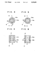
- FIG. 6 is a cross-sectional view of the catalyst portion of FIG. 5 taken along line 6--6;
- FIG. 7 is a flow chart for EGR control
- FIG. 8 is a flow chart for fuel injection control
- FIG. 9 is a flow chart for control of a flow switching valve
- FIG. 11 is a graph illustrating a relationship between NOx purification rate and a ratio of melting-out of copper ion into condensate water on a lean NOx catalyst.
- FIG. 12 is a flow chart for control of secondary air introduction.
- FIG. 1 illustrates an arrangement of an exhaust gas purification system in accordance with a first embodiment of the invention.
- a dual passage portion 6 is provided in an exhaust conduit 24 of an internal combustion engine 2 capable of fuel combustion at lean air-fuel ratios.
- the dual passage portion 6 is located downstream of and close to an exhaust manifold 4 of the engine.
- the dual passage portion 6 includes a first passage 6a and a second passage 6b which are connected in parallel to each other.
- the first passage 6a and the second passage 6b are separate from each other at the longitudinally intermediate portions of the first and second passages 6a and 6b.
- a first catalyst 10 constructed of lean NOx catalyst is installed and a second catalyst 12 constructed of either a three-way or an oxidizing catalyst is further installed downstream of the first catalyst 10.
- a lean NOx catalyst is defined as a catalyst constructed of zeolite carrying at least one metal selected from the group consisting of transition metals and noble metals to reduce nitrogen oxides included in exhaust gas from the engine under oxidizing conditions and in the presence of hydrocarbons.
- a third catalyst 8 constructed of either a three-way or an oxidizing catalyst is installed.
- a flow switching valve 14 for switching the exhaust gas flow between the first passage 6a and the second passage 6b is installed at an upstream side connecting portion of the first passage 6a and the second passage 6b.
- the flow switching valve 14 is coupled to a valve actuator which is electrically connected to and is operated by a micro computer (valve control means) for controlling the switching operation of the flow switching valve 14.
- the computer includes an input/output interface, a central processor unit for executing calculation, a read only memory storing various programs including routines of FIGS. 7, 8, 9, and 12, and a random access memory.
- the computer controls the flow switching valve 14 so that the flow switching valve 14 causes exhaust gas to flow through the second passage 6b while the engine is being warmed-up and causes exhaust gas to flow through the first passage 6a after the engine has been warmed-up.
- An engine recirculation system 16 is also provided so that a portion of exhaust gas is recirculated to an intake manifold 18 of the engine.
- a fourth catalyst 22 constructed of a three-way catalyst may be installed in a portion of the exhaust conduit downstream of the dual passage portion 6.
- FIGS. 2-6 illustrate arrangements of exhaust gas purification systems in accordance with a second embodiment and a third embodiment of the invention. Since the second embodiment and the third embodiment differ from the first embodiment in the structures of the dual passage portions thereof only, explanation of the portions of the second embodiment and the third embodiment having the same structures as those of the first embodiment will be omitted by denoting like reference numerals, and the different portions only will be explained below.
- a dual passage portion 26 which corresponds to the dual passage portion 6 of the first embodiment, is provided downstream of and close to the exhaust manifold 4 of the engine 2.
- the dual passage portion 26 includes a first passage 26a and a second passage 26b which are connected in parallel to each other.
- the first passage 26a and the second passage 26b contact each other, and the second passage 26b surrounds the first passage 26a.
- the first catalyst 10 constructed of lean NOx catalyst is installed and the second catalyst 12 constructed of either three-way or oxidizing catalyst is installed downstream of the first catalyst 10.
- the third catalyst 8 constructed of either three-way or oxidizing catalyst is installed.
- a dual passage portion 36 which corresponds to the dual passage portion 6 of the first embodiment, is provided downstream of and close to the exhaust manifold 4 of the engine 2.
- the dual passage portion 36 includes a first passage 36a and a second passage 36b which are connected in parallel to each other.
- the first passage 36a and the second passage 36b contact each other, and the first passage 36a surrounds the second passage 36b.
- the first catalyst 10 constructed of lean NOx catalyst
- the second catalyst 12 constructed of either three-way or oxidizing catalyst is installed downstream of the first catalyst 10.
- the third catalyst 8 constructed of either three-way or oxidizing catalyst is installed.
- the dual passage portions 26 and 36 of the second and third embodiments are more compact in size than the dual passage portion 6 of the first embodiment.
- a secondary air introduction port 20 is provided in the first passage 6a of the dual passage portion 6 upstream of the first catalyst 10 constructed of lean NOx catalyst. Secondary air is introduced for a predetermined period of time after stopping of the engine through the secondary air introduction port 20 so that water is prevented from being condensed on the first catalyst 10 of lean NOx catalyst from vapour included in the exhaust gas.
- control for EGR control for fuel injection
- control for switching of the switching valve 14 control for introduction of secondary air
- FIG. 7 illustrates a routine for controlling EGR.
- the amount of EGR affects a fuel injection amount modification factor KLEAN (which will be described hereinafter) which in turn affects an air-fuel ratio, a NOx amount, HC and CO emissions, and a switching timing of the flow switching valve 14.
- KLEAN fuel injection amount modification factor
- the routine of FIG. 7 is entered at intervals of predetermined periods of time.
- the routine proceeds to step 106 where flag XEGR is set to "0" and then returns, because EGR should not be executed at low temperatures including engine start-up and idling conditions.
- the routine proceeds to step 102.
- step 103 the opening degree obtained at step 102 is fed to a step motor (not shown) for opening and closing the EGR valve of the EGR device 16.
- step 104 it is determined whether or not the EGR is in the state of "ON".
- the routine proceeds to step 105, where the EGR flag XEGR is set to "1".
- step 106 the EGR flag XEGR is set to "0". The EGR flag XEGR will be used in the routing of FIG. 8.
- a pressure increment PT of the intake pressure PM due to execution of EGR is calculated.
- the pressure increment PT is dependent on the opening degree of the EGR valve and the engine speed NE. More particularly, PM changes in proportion to the opening degree of the EGR valve and in inverse proportion to the engine speed NE. For the purpose of calculating PT more exactly, a predetermined map may be used.
- an intake pressure component PM' of a newly suctioned intake gas (excluding EGR gas) is calculated by the following equation:
- PM is an intake pressure detected by a pressure sensor (not shown), and PT is an increment of the intake pressure due to execution of EGR.
- the above-described fuel injection modification factor KLEAN is also used for control of switching of the flow switching valve 14 in accordance with a routine of FIG. 9.
- FIG. 9 illustrates a routine for controlling switching of the flow switching valve 14.
- the routine of FIG. 9 is entered at intervals of predetermined periods of time.
- the current engine cooling water temperature TW and the current fuel injection amount modification factor KLEAN are entered in the computer.
- step 302 it is determined whether or not the current TW is smaller than a predetermined temperature TWO.
- TW is determined to be smaller than TWO
- the current engine operating condition is deemed to be in a warming-up condition and the routine proceeds to step 303 and then to steps 304 and 305.
- TW is determined to not be smaller than TWO at step 302
- the current engine operating condition is deemed to be in a warmed-up condition, and the routine proceeds to step 306.
- setting "1" (bypass "ON”) of FB1 corresponds to a state where the exhaust gas bypasses the first catalyst 10 of lean NOx catalyst and flows through the third catalyst 8 of three-way or oxidizing catalyst
- setting "0" (bypass "OFF") of FB1 corresponds to a state where the exhaust gas flows through the first catalyst of lean NOx catalyst.
- step 303 When the routine proceeds to step 303 and FB1 is determined to be not at “0”, the routine returns without executing any action.
- FB1 is determined to be at "0" at step 303 and therefore the exhaust gas is flowing through the lean NOx catalyst, the routine proceeds to step 304, where the flow switching valve 14 is switched to "ON" so that the exhaust gas flows through the third catalyst 8 of oxidizing or three-way catalyst. Then, the routine proceeds to step 305 where bypass flag FB1 is set to "1".
- step 306 it is determined whether or not the fuel injection amount modification factor KLEAN is greater than 1.0.
- KLEAN is determined to be greater than 1.0 at step 306, the current air-fuel ratio is deemed to be in a rich or stoichiometric condition. Therefore, the flow switching valve 14 is controlled in accordance with the steps 303 to 305 so that the exhaust gas flows through the third catalyst 8 of three-way or oxidizing catalyst.
- step 307 it is determined whether of not the bypass flag FB1 is at "0".
- the routine returns without executing any action because the exhaust gas is flowing through the first catalyst 10 of lean NOx catalyst.
- step 308 the flow switching valve 14 is switched to "OFF” so that the exhaust gas flows through the first catalyst 10 of lean NOx catalyst.
- step 309 the bypass flag FB1 is set to "0".
- exhaust gas flows through the third catalyst 8 of three-way or oxidizing catalyst when the engine is being warmed-up (TW is smaller than TWO) and when the throttle valve is in a full-open state (KLEAN is equal to or larger than 1.0) even if the engine is in a warmed-up condition.
- exhaust gas flows through the first catalyst 10 of lean NOx catalyst and the second catalyst 12 after the engine has been warmed-up (TW is equal to or larger than TWO) and the throttle valve is not in a full-open state (KLEAN is smaller than 1.0).
- control structures are application to the first to third embodiments.
- FIG. 12 illustrates a routine for control for supply of secondary air which is application to the fourth embodiment of FIG. 10 only.
- the routine of FIG. 12 is a routine for control of supply of secondary air for the purpose of preventing vapour included in the exhaust gas remaining in the exhaust conduit after stopping of the engine from being condensed to generate water which will collect on the first catalyst 10 of lean NOx catalyst. If water collects on the lean NOx catalyst, copper ion carried by the zeolite of the lean NOx catalyst dissolves into the condensate water to degrade the NOx purification rate of the lean NOx catalyst as shown in FIG. 11. In this instance, the transition metal, for example, copper is carried in the form of ion by the zeolite of the lean NOx catalyst.
- the routine of FIG. 12 is entered at intervals of predetermined periods of time.
- the routine returns without executing any action, because vapour is not condensed on the lean NOx catalyst.
- step 402 it is determined whether or not an ignition key is turned to "OFF".
- the routine returns without executing any action.
- the routine proceeds to step 403, where supply of secondary air is switched to "ON” so that secondary air is supplied through the secondary air introduction port 20 to a portion of the first passage upstream of the lean NOx catalyst.
- the routine proceeds to step 404 where timer counting starts and then to step 405 where whether or not the counted time (t) exceeds a predetermined time (te) is determined. Until the increasing time (t) exceeds the predetermined time (te), the routine is repeatedly executed so that supply of secondary air continues.
- step 406 supply of secondary air is switched to "OFF” and stops. Then, at step 407, the timer is turned to "OFF” and the counted time (t) is cleared.
- the flow switching valve 14 is controlled so as to cause exhaust gas to flow through the third catalyst 8 of oxidizing or three-way catalyst during warming-up of the engine and since the third catalyst 8 is located close to the exhaust manifold 4, the third catalyst 8 is quickly warmed-up so that HC and CO emissions are effectively purified. Also, the flow switching valve 14 is controlled so as to cause exhaust gas to flow through the first catalyst 10 of lean NOx catalyst after the engine has been warmed-up, NOx and a portion of HC and CO emissions are purified by the lean NOx catalyst and the remaining portion of HC and CO emissions which could not be purified by the lean NOx catalyst is purified by the second catalyst 12 located downstream of the first catalyst 10.
- a catalytic converter including the first through third catalysts can be designed compact and a good warming-up characteristic of, one catalyst surrounded by the other catalyst is obtained.
Abstract
Description
PM'=PN-PT
KLEAN=PMLEAN×NELEAN
TAU=TP×KLEAN×A+B
Claims (8)
Priority Applications (1)
| Application Number | Priority Date | Filing Date | Title |
|---|---|---|---|
| US08/060,375 US5365733A (en) | 1990-05-28 | 1993-05-07 | Exhaust gas purification system for an internal combustion engine |
Applications Claiming Priority (2)
| Application Number | Priority Date | Filing Date | Title |
|---|---|---|---|
| JP2-135233 | 1990-05-28 | ||
| JP2135233A JP2712758B2 (en) | 1990-05-28 | 1990-05-28 | Exhaust gas purification device for internal combustion engine |
Related Child Applications (1)
| Application Number | Title | Priority Date | Filing Date |
|---|---|---|---|
| US08/060,375 Continuation US5365733A (en) | 1990-05-28 | 1993-05-07 | Exhaust gas purification system for an internal combustion engine |
Publications (1)
| Publication Number | Publication Date |
|---|---|
| US5233830A true US5233830A (en) | 1993-08-10 |
Family
ID=15146925
Family Applications (2)
| Application Number | Title | Priority Date | Filing Date |
|---|---|---|---|
| US07/709,000 Expired - Fee Related US5233830A (en) | 1990-05-28 | 1991-05-21 | Exhaust gas purification system for an internal combustion engine |
| US08/060,375 Expired - Fee Related US5365733A (en) | 1990-05-28 | 1993-05-07 | Exhaust gas purification system for an internal combustion engine |
Family Applications After (1)
| Application Number | Title | Priority Date | Filing Date |
|---|---|---|---|
| US08/060,375 Expired - Fee Related US5365733A (en) | 1990-05-28 | 1993-05-07 | Exhaust gas purification system for an internal combustion engine |
Country Status (5)
| Country | Link |
|---|---|
| US (2) | US5233830A (en) |
| EP (1) | EP0460507B1 (en) |
| JP (1) | JP2712758B2 (en) |
| CA (1) | CA2043295C (en) |
| DE (1) | DE69113119T2 (en) |
Cited By (87)
| Publication number | Priority date | Publication date | Assignee | Title |
|---|---|---|---|---|
| US5349816A (en) * | 1992-02-20 | 1994-09-27 | Mitsubishi Jidosha Kogyo Kabushiki Kaisha | Exhaust emission control system |
| US5377486A (en) * | 1993-05-17 | 1995-01-03 | Ford Motor Company | Catalytic converter system |
| US5423181A (en) * | 1992-09-02 | 1995-06-13 | Toyota Jidosha Kabushiki Kaisha | Exhaust gas purification device of an engine |
| US5437153A (en) * | 1992-06-12 | 1995-08-01 | Toyota Jidosha Kabushiki Kaisha | Exhaust purification device of internal combustion engine |
| US5473887A (en) * | 1991-10-03 | 1995-12-12 | Toyota Jidosha Kabushiki Kaisha | Exhaust purification device of internal combustion engine |
| US5510086A (en) * | 1995-04-10 | 1996-04-23 | General Motors Corporation | Adcat exhaust treatment device |
| US5578277A (en) * | 1994-06-24 | 1996-11-26 | Caterpillar Inc. | Modular catalytic converter and muffler for internal combustion engine |
| US5611198A (en) * | 1994-08-16 | 1997-03-18 | Caterpillar Inc. | Series combination catalytic converter |
| US5619853A (en) * | 1995-12-26 | 1997-04-15 | Corning Incorporated | Exhaust system with a fluidics apparatus diverter body having extensions |
| WO1998000222A1 (en) * | 1996-07-03 | 1998-01-08 | Low Emissions Technologies Research And Development Partnership | Material and system for catalytic reduction of nitrogen oxide in an exhaust stream of a combustion process |
| US5732554A (en) * | 1995-02-14 | 1998-03-31 | Toyota Jidosha Kabushiki Kaisha | Exhaust gas purification device for an internal combustion engine |
| US5771690A (en) * | 1996-01-22 | 1998-06-30 | Nissan Motor Co., Ltd. | Engine exhaust purifier |
| US5787708A (en) * | 1995-12-15 | 1998-08-04 | Caterpillar Inc. | Combustion exhaust purification system and method via high sac volume fuel injectors |
| US5832722A (en) * | 1997-03-31 | 1998-11-10 | Ford Global Technologies, Inc. | Method and apparatus for maintaining catalyst efficiency of a NOx trap |
| US5894725A (en) * | 1997-03-27 | 1999-04-20 | Ford Global Technologies, Inc. | Method and apparatus for maintaining catalyst efficiency of a NOx trap |
| US5897846A (en) * | 1997-01-27 | 1999-04-27 | Asec Manufacturing | Catalytic converter having a catalyst with noble metal on molecular sieve crystal surface and method of treating diesel engine exhaust gas with same |
| US5950423A (en) * | 1997-06-27 | 1999-09-14 | Corning Incorporated | In-line exhaust system for a transverse mounted v-engine |
| US5966929A (en) * | 1997-06-27 | 1999-10-19 | Corning Incorporated | In-line exhaust system for a transverse mounted v-engine |
| US5992142A (en) * | 1996-09-28 | 1999-11-30 | Volkswagen Ag | No exhaust emission control method and arrangement |
| US6161378A (en) * | 1996-06-10 | 2000-12-19 | Hitachi, Ltd. | Exhaust gas purification apparatus of internal combustion engine and catalyst for purifying exhaust gas internal combustion engine |
| US6212885B1 (en) * | 1998-04-28 | 2001-04-10 | Toyota Jidosha Kabushiki Kaisha | Exhaust emission control system of internal combustion engine |
| US6308697B1 (en) | 2000-03-17 | 2001-10-30 | Ford Global Technologies, Inc. | Method for improved air-fuel ratio control in engines |
| US6308515B1 (en) | 2000-03-17 | 2001-10-30 | Ford Global Technologies, Inc. | Method and apparatus for accessing ability of lean NOx trap to store exhaust gas constituent |
| US6327847B1 (en) | 2000-03-17 | 2001-12-11 | Ford Global Technologies, Inc. | Method for improved performance of a vehicle |
| US20020007628A1 (en) * | 2000-03-17 | 2002-01-24 | Bidner David Karl | Method for determining emission control system operability |
| US6360530B1 (en) | 2000-03-17 | 2002-03-26 | Ford Global Technologies, Inc. | Method and apparatus for measuring lean-burn engine emissions |
| US6370868B1 (en) | 2000-04-04 | 2002-04-16 | Ford Global Technologies, Inc. | Method and system for purge cycle management of a lean NOx trap |
| US6374597B1 (en) | 2000-03-17 | 2002-04-23 | Ford Global Technologies, Inc. | Method and apparatus for accessing ability of lean NOx trap to store exhaust gas constituent |
| US6389803B1 (en) | 2000-08-02 | 2002-05-21 | Ford Global Technologies, Inc. | Emission control for improved vehicle performance |
| US6422006B2 (en) * | 2000-06-27 | 2002-07-23 | Honda Giken Kogyo Kabushiki Kaisha | Exhaust gas purifying apparatus for internal combustion engine |
| US6427437B1 (en) | 2000-03-17 | 2002-08-06 | Ford Global Technologies, Inc. | Method for improved performance of an engine emission control system |
| US6434930B1 (en) | 2000-03-17 | 2002-08-20 | Ford Global Technologies, Inc. | Method and apparatus for controlling lean operation of an internal combustion engine |
| US6438944B1 (en) | 2000-03-17 | 2002-08-27 | Ford Global Technologies, Inc. | Method and apparatus for optimizing purge fuel for purging emissions control device |
| US6453666B1 (en) | 2001-06-19 | 2002-09-24 | Ford Global Technologies, Inc. | Method and system for reducing vehicle tailpipe emissions when operating lean |
| US6463733B1 (en) | 2001-06-19 | 2002-10-15 | Ford Global Technologies, Inc. | Method and system for optimizing open-loop fill and purge times for an emission control device |
| US6467259B1 (en) | 2001-06-19 | 2002-10-22 | Ford Global Technologies, Inc. | Method and system for operating dual-exhaust engine |
| US6477832B1 (en) | 2000-03-17 | 2002-11-12 | Ford Global Technologies, Inc. | Method for improved performance of a vehicle having an internal combustion engine |
| US6481199B1 (en) | 2000-03-17 | 2002-11-19 | Ford Global Technologies, Inc. | Control for improved vehicle performance |
| US6487853B1 (en) | 2001-06-19 | 2002-12-03 | Ford Global Technologies. Inc. | Method and system for reducing lean-burn vehicle emissions using a downstream reductant sensor |
| US6487850B1 (en) | 2000-03-17 | 2002-12-03 | Ford Global Technologies, Inc. | Method for improved engine control |
| US6487849B1 (en) | 2000-03-17 | 2002-12-03 | Ford Global Technologies, Inc. | Method and apparatus for controlling lean-burn engine based upon predicted performance impact and trap efficiency |
| US6490860B1 (en) | 2001-06-19 | 2002-12-10 | Ford Global Technologies, Inc. | Open-loop method and system for controlling the storage and release cycles of an emission control device |
| US6499293B1 (en) | 2000-03-17 | 2002-12-31 | Ford Global Technologies, Inc. | Method and system for reducing NOx tailpipe emissions of a lean-burn internal combustion engine |
| US6502387B1 (en) | 2001-06-19 | 2003-01-07 | Ford Global Technologies, Inc. | Method and system for controlling storage and release of exhaust gas constituents in an emission control device |
| US6539704B1 (en) | 2000-03-17 | 2003-04-01 | Ford Global Technologies, Inc. | Method for improved vehicle performance |
| US6539706B2 (en) | 2001-06-19 | 2003-04-01 | Ford Global Technologies, Inc. | Method and system for preconditioning an emission control device for operation about stoichiometry |
| US6546718B2 (en) | 2001-06-19 | 2003-04-15 | Ford Global Technologies, Inc. | Method and system for reducing vehicle emissions using a sensor downstream of an emission control device |
| US6553754B2 (en) | 2001-06-19 | 2003-04-29 | Ford Global Technologies, Inc. | Method and system for controlling an emission control device based on depletion of device storage capacity |
| US6568177B1 (en) | 2002-06-04 | 2003-05-27 | Ford Global Technologies, Llc | Method for rapid catalyst heating |
| US6594989B1 (en) | 2000-03-17 | 2003-07-22 | Ford Global Technologies, Llc | Method and apparatus for enhancing fuel economy of a lean burn internal combustion engine |
| US6596247B1 (en) | 1996-10-25 | 2003-07-22 | Hitachi, Ltd. | Method for purifying exhaust gas from internal combustion engines |
| US6604504B2 (en) | 2001-06-19 | 2003-08-12 | Ford Global Technologies, Llc | Method and system for transitioning between lean and stoichiometric operation of a lean-burn engine |
| US6615577B2 (en) | 2001-06-19 | 2003-09-09 | Ford Global Technologies, Llc | Method and system for controlling a regeneration cycle of an emission control device |
| US6629453B1 (en) | 2000-03-17 | 2003-10-07 | Ford Global Technologies, Llc | Method and apparatus for measuring the performance of an emissions control device |
| US20030192306A1 (en) * | 2002-04-15 | 2003-10-16 | Toyota Jidosha Kabushiki Kaisha | Internal combustion engine emission control apparatus and method |
| US6650991B2 (en) | 2001-06-19 | 2003-11-18 | Ford Global Technologies, Llc | Closed-loop method and system for purging a vehicle emission control |
| US20030221419A1 (en) * | 2002-06-04 | 2003-12-04 | Ford Global Technologies, Inc. | Method for controlling the temperature of an emission control device |
| US20030221416A1 (en) * | 2002-06-04 | 2003-12-04 | Ford Global Technologies, Inc. | Method and system for rapid heating of an emission control device |
| US20030221671A1 (en) * | 2002-06-04 | 2003-12-04 | Ford Global Technologies, Inc. | Method for controlling an engine to obtain rapid catalyst heating |
| US6691020B2 (en) | 2001-06-19 | 2004-02-10 | Ford Global Technologies, Llc | Method and system for optimizing purge of exhaust gas constituent stored in an emission control device |
| US6694244B2 (en) | 2001-06-19 | 2004-02-17 | Ford Global Technologies, Llc | Method for quantifying oxygen stored in a vehicle emission control device |
| US6691507B1 (en) | 2000-10-16 | 2004-02-17 | Ford Global Technologies, Llc | Closed-loop temperature control for an emission control device |
| US6708483B1 (en) | 2000-03-17 | 2004-03-23 | Ford Global Technologies, Llc | Method and apparatus for controlling lean-burn engine based upon predicted performance impact |
| US6715462B2 (en) | 2002-06-04 | 2004-04-06 | Ford Global Technologies, Llc | Method to control fuel vapor purging |
| US6725830B2 (en) | 2002-06-04 | 2004-04-27 | Ford Global Technologies, Llc | Method for split ignition timing for idle speed control of an engine |
| US6736120B2 (en) | 2002-06-04 | 2004-05-18 | Ford Global Technologies, Llc | Method and system of adaptive learning for engine exhaust gas sensors |
| US6735940B2 (en) | 2002-07-11 | 2004-05-18 | Fleetguard, Inc. | Adsorber aftertreatment system having dual adsorbers |
| US6735938B2 (en) | 2002-06-04 | 2004-05-18 | Ford Global Technologies, Llc | Method to control transitions between modes of operation of an engine |
| US6736121B2 (en) | 2002-06-04 | 2004-05-18 | Ford Global Technologies, Llc | Method for air-fuel ratio sensor diagnosis |
| US6745560B2 (en) | 2002-07-11 | 2004-06-08 | Fleetguard, Inc. | Adsorber aftertreatment system having dual soot filters |
| US6745747B2 (en) | 2002-06-04 | 2004-06-08 | Ford Global Technologies, Llc | Method for air-fuel ratio control of a lean burn engine |
| US6758185B2 (en) | 2002-06-04 | 2004-07-06 | Ford Global Technologies, Llc | Method to improve fuel economy in lean burn engines with variable-displacement-like characteristics |
| US6769398B2 (en) | 2002-06-04 | 2004-08-03 | Ford Global Technologies, Llc | Idle speed control for lean burn engine with variable-displacement-like characteristic |
| US20040182365A1 (en) * | 2002-06-04 | 2004-09-23 | Gopichandra Surnilla | Method for controlling transitions between operating modes of an engine for rapid heating of an emission control device |
| US20040200212A1 (en) * | 2003-01-20 | 2004-10-14 | Kozo Katogi | Exhaust gas purifier |
| US6820414B2 (en) | 2002-07-11 | 2004-11-23 | Fleetguard, Inc. | Adsorber aftertreatment system having downstream soot filter |
| US6843051B1 (en) | 2000-03-17 | 2005-01-18 | Ford Global Technologies, Llc | Method and apparatus for controlling lean-burn engine to purge trap of stored NOx |
| US6860100B1 (en) | 2000-03-17 | 2005-03-01 | Ford Global Technologies, Llc | Degradation detection method for an engine having a NOx sensor |
| US20050091965A1 (en) * | 2002-02-14 | 2005-05-05 | Klaus Ries-Mueller | Method and device for operating an internal combustion engine |
| US6925982B2 (en) | 2002-06-04 | 2005-08-09 | Ford Global Technologies, Llc | Overall scheduling of a lean burn engine system |
| WO2006048728A1 (en) | 2004-11-04 | 2006-05-11 | Eaton Corporation | Multiple reactant multiple catalyst selective catalytic reduction for nox abatement in internal combustion engines |
| US20070175206A1 (en) * | 2002-07-11 | 2007-08-02 | Rahul Mital | NOx adsorber aftertreatment system for internal combustion engines |
| US20080271442A1 (en) * | 2007-05-04 | 2008-11-06 | Thomas Baumgartner | Exhaust Gas System for an Internal Combustion Engine |
| US20100037607A1 (en) * | 2008-08-12 | 2010-02-18 | Man Nutzfahrzeuge Ag | Method and device for the regeneration of a particle filter arranged in the exhaust gas tract of an internal combustion engine |
| US20110289903A1 (en) * | 2009-01-22 | 2011-12-01 | Man Truck & Bus Ag | Device and method for regenerating a particulate filter arranged in the exhaust section of an internal combustion engine |
| US20140130769A1 (en) * | 2005-07-19 | 2014-05-15 | Avl List Gmbh | Exhaust gas line of an internal combustion engine |
| US20170226938A1 (en) * | 2016-02-05 | 2017-08-10 | Ford Global Technologies, Llc | Auto-ignition internal combustion engine suitable for hcci operation, and method for operating an internal combustion engine of said type |
Families Citing this family (43)
| Publication number | Priority date | Publication date | Assignee | Title |
|---|---|---|---|---|
| JPH04224223A (en) * | 1990-12-20 | 1992-08-13 | Mitsubishi Heavy Ind Ltd | Purification method for exhaust gas |
| JP2887984B2 (en) * | 1991-09-20 | 1999-05-10 | トヨタ自動車株式会社 | Exhaust gas purification device for internal combustion engine |
| US5185305A (en) * | 1991-11-08 | 1993-02-09 | Ford Motor Company | Catalyst system for treating the exhaust from a lean-burn gasoline-fueled engine |
| JPH0693839A (en) * | 1992-09-10 | 1994-04-05 | Hitachi Ltd | Exhaust emission control device for internal combustion engine |
| FR2698909B1 (en) * | 1992-12-04 | 1994-12-30 | Renault | Exhaust device for internal combustion engine. |
| EP0605991A1 (en) * | 1993-01-07 | 1994-07-13 | Ford Motor Company Limited | Base metal only catalyst system for internal combustion engines |
| JPH06272542A (en) * | 1993-03-17 | 1994-09-27 | Hitachi Ltd | Apparatus and method for controlling exhaust emission of internal combustion engine |
| DE4406648C1 (en) * | 1994-03-01 | 1995-08-10 | Daimler Benz Ag | Catalytic reduction of hydrocarbons, carbon monoxide and nitrogen oxides from i.c engine exhaust |
| US5609022A (en) * | 1994-10-31 | 1997-03-11 | General Motors Corporation | Method of reducing NOx emissions from lean-burn combustion engines |
| DE19529835A1 (en) * | 1995-08-12 | 1997-02-13 | Opel Adam Ag | Exhaust system of a gasoline engine |
| DE19617563C2 (en) * | 1996-05-02 | 2000-06-15 | Daimler Chrysler Ag | Catalytic converter system for a diesel engine |
| DE19643053C1 (en) * | 1996-10-18 | 1997-07-10 | Daimler Benz Ag | Exhaust nitrogen oxide emissions reduction method for directly fuel-injected IC engine |
| DE19709102A1 (en) * | 1997-03-06 | 1998-10-08 | Degussa | Catalyst system for exhaust gas purification of diesel engines |
| JP2000066819A (en) | 1998-08-18 | 2000-03-03 | Matsushita Electric Ind Co Ltd | General-purpose chinese voice keyboard setting device |
| DE19904314A1 (en) * | 1999-01-28 | 2000-08-17 | Porsche Ag | Exhaust gas purifying device has a catalyst arrangement consisting of a main catalyst and several pre-catalysts arranged relatively near to the cylinder head |
| JP4330048B2 (en) * | 1999-06-11 | 2009-09-09 | ヤマハ発動機株式会社 | Multi-cylinder 4-cycle engine for outboard motor |
| DE19928559C2 (en) * | 1999-06-22 | 2003-03-20 | Bayerische Motoren Werke Ag | Method for determining the end of the dew point when controlling exhaust-gas-related functions in a motor vehicle |
| JP2003065095A (en) * | 2001-08-27 | 2003-03-05 | Yanmar Co Ltd | Operation control method for internal combustion engine |
| GB2389918A (en) * | 2002-06-21 | 2003-12-24 | Lotus Car | De-activation of combustion chambers in a multi-combustion chamber i.c. engine |
| US6679051B1 (en) * | 2002-07-31 | 2004-01-20 | Ford Global Technologies, Llc | Diesel engine system for use with emission control device |
| US6694727B1 (en) | 2002-09-03 | 2004-02-24 | Arvin Technologies, Inc. | Exhaust processor |
| US7341699B2 (en) * | 2002-09-03 | 2008-03-11 | Arvin Technologies, Inc. | Emission abatement device and method of using same |
| GB2408470B (en) * | 2003-11-25 | 2007-06-13 | Arvin Internat | An internal combustion engine exhaust system |
| DE102005006122A1 (en) * | 2004-02-11 | 2005-09-15 | Arvin Technologies, Inc., Troy | Particulate filter assembly for trapping particulate matter in exhaust gas from internal combustion engines, has conductor for mounting filter in tube and defining exhaust gas outlet passageway to conduct exhaust gas to end cap outlet |
| DE102004008415A1 (en) * | 2004-02-20 | 2005-09-01 | Arvin Technologies, Inc., Troy | Device for cleaning vehicle exhaust gases, in particular diesel soot filters |
| DE102004013458A1 (en) * | 2004-03-18 | 2005-10-20 | Arvin Technologies Inc | Device for cleaning vehicle exhaust gases |
| DE102004016690A1 (en) * | 2004-04-05 | 2005-10-27 | Arvin Technologies, Inc., Troy | Device for cleaning vehicle exhaust gases, in particular diesel soot filters, and vehicle with corresponding device |
| US7776280B2 (en) | 2005-05-10 | 2010-08-17 | Emcon Technologies Llc | Method and apparatus for selective catalytic reduction of NOx |
| US20060254260A1 (en) * | 2005-05-16 | 2006-11-16 | Arvinmeritor Emissions Technologies Gmbh | Method and apparatus for piezoelectric injection of agent into exhaust gas for use with emission abatement device |
| US7246005B2 (en) * | 2005-06-07 | 2007-07-17 | Arvin Technologies, Inc. | Method and apparatus for controlling a component by feed-forward closed-loop controller state modification |
| US7332142B2 (en) * | 2005-06-17 | 2008-02-19 | Emcon Tehnologies Germany (Augsburg) Gmbh | Method and apparatus for bubble injection of agent into exhaust gas for use with emission abatement device |
| AT500737B1 (en) * | 2005-12-06 | 2008-06-15 | Avl List Gmbh | Spark-ignition internal combustion engine for vehicle, has water injection device injecting water into exhaust gas line, where injection device opens upstream of upstream of turbine of turbocharger into exhaust gas line |
| AT503124B1 (en) * | 2006-05-05 | 2007-08-15 | Man Nutzfahrzeuge Oesterreich | Exhaust system for internal combustion engine of e.g. automobile, has hydrolysis catalyzer attached with oxidation catalyzer, where reduction agent is injected in tubular section of string, and ammonia is produced by hydrolysis catalyzer |
| US20080286177A1 (en) * | 2007-05-18 | 2008-11-20 | Tribute Creations, Llc | Reactor with differentially distributed catalytic activity |
| DE102007053932A1 (en) * | 2007-11-13 | 2009-05-14 | Bayerische Motoren Werke Aktiengesellschaft | Exhaust system and method for operating the same |
| US20110041482A1 (en) * | 2009-08-20 | 2011-02-24 | Gm Global Technology Operations, Inc. | Method and apparatus for exhaust aftertreatment of an internal combustion engine |
| DE102009058713A1 (en) * | 2009-12-17 | 2011-06-22 | Deutz Ag, 51149 | Method for exhaust gas recirculation |
| FI124642B (en) | 2012-10-09 | 2014-11-14 | Wärtsilä Finland Oy | Piston engine catalytic converter unit and supercharged piston engine |
| IL223937A (en) | 2012-12-27 | 2016-12-29 | Vladimir N Filatov | High voltage transmission line cable based on textile composite material |
| DE102013213292B4 (en) | 2013-07-08 | 2015-02-26 | Ford Global Technologies, Llc (N.D.Ges.D. Staates Delaware) | Combustion engine with cylinder deactivation and method for cylinder deactivation |
| DE102013213294A1 (en) | 2013-07-08 | 2015-01-08 | Ford Global Technologies, Llc (N.D.Ges.D. Staates Delaware) | Combustion engine with cylinder deactivation and method for cylinder deactivation |
| DE202013103022U1 (en) | 2013-07-08 | 2013-07-18 | Ford Global Technologies, Llc | Internal combustion engine with cylinder deactivation |
| DE102018104588B4 (en) * | 2018-02-28 | 2022-07-07 | Tenneco Gmbh | Emission control unit, emission control system and method for cleaning |
Citations (7)
| Publication number | Priority date | Publication date | Assignee | Title |
|---|---|---|---|---|
| US3072458A (en) * | 1960-05-31 | 1963-01-08 | Universal Oil Prod Co | Method of catalytically purifying exhaust gases of internal combustion engines and cyclically regenerating the lead-contaminated catalyst |
| US3476508A (en) * | 1965-10-27 | 1969-11-04 | Exxon Research Engineering Co | Catalytic purification treatment of exhaust gas |
| GB1314504A (en) * | 1971-01-19 | 1973-04-26 | British Leyland Motor Corp | Exhaust systems for internal combustion engines |
| US3793830A (en) * | 1972-05-19 | 1974-02-26 | P August | Device for the after treatment of exhaust gases of an internal combustion engine |
| GB1347542A (en) * | 1971-07-10 | 1974-02-27 | Ford Motor Co | Catalyst converter assembly for an internal combustion engine |
| DE2259946A1 (en) * | 1972-12-07 | 1974-06-27 | August Paul Dipl Ing Dr H C | AFTERBURN DEVICE FOR THE REMOVAL OF TOXIC COMPONENTS IN THE EXHAUST GASES FROM COMBUSTION MACHINES |
| US4297328A (en) * | 1979-09-28 | 1981-10-27 | Union Carbide Corporation | Three-way catalytic process for gaseous streams |
Family Cites Families (4)
| Publication number | Priority date | Publication date | Assignee | Title |
|---|---|---|---|---|
| GB1334797A (en) * | 1970-11-20 | 1973-10-24 | British Leyland Motor Corp | Exhaust systems for internal combustion engines |
| US3949551A (en) * | 1972-01-29 | 1976-04-13 | Robert Bosch G.M.B.H. | Method and system for reducing noxious components in the exhaust emission of internal combustion engine systems and particularly during the warm-up phase of the engine |
| DE3629945A1 (en) * | 1986-09-03 | 1987-10-01 | Daimler Benz Ag | Device for aftertreatment of the exhaust gases of an internal combustion engine |
| JPS6439145A (en) * | 1987-08-03 | 1989-02-09 | Nec Corp | Circuit for switching data transfer timing |
-
1990
- 1990-05-28 JP JP2135233A patent/JP2712758B2/en not_active Expired - Fee Related
-
1991
- 1991-05-21 US US07/709,000 patent/US5233830A/en not_active Expired - Fee Related
- 1991-05-27 CA CA002043295A patent/CA2043295C/en not_active Expired - Fee Related
- 1991-05-27 EP EP91108708A patent/EP0460507B1/en not_active Expired - Lifetime
- 1991-05-27 DE DE69113119T patent/DE69113119T2/en not_active Expired - Fee Related
-
1993
- 1993-05-07 US US08/060,375 patent/US5365733A/en not_active Expired - Fee Related
Patent Citations (7)
| Publication number | Priority date | Publication date | Assignee | Title |
|---|---|---|---|---|
| US3072458A (en) * | 1960-05-31 | 1963-01-08 | Universal Oil Prod Co | Method of catalytically purifying exhaust gases of internal combustion engines and cyclically regenerating the lead-contaminated catalyst |
| US3476508A (en) * | 1965-10-27 | 1969-11-04 | Exxon Research Engineering Co | Catalytic purification treatment of exhaust gas |
| GB1314504A (en) * | 1971-01-19 | 1973-04-26 | British Leyland Motor Corp | Exhaust systems for internal combustion engines |
| GB1347542A (en) * | 1971-07-10 | 1974-02-27 | Ford Motor Co | Catalyst converter assembly for an internal combustion engine |
| US3793830A (en) * | 1972-05-19 | 1974-02-26 | P August | Device for the after treatment of exhaust gases of an internal combustion engine |
| DE2259946A1 (en) * | 1972-12-07 | 1974-06-27 | August Paul Dipl Ing Dr H C | AFTERBURN DEVICE FOR THE REMOVAL OF TOXIC COMPONENTS IN THE EXHAUST GASES FROM COMBUSTION MACHINES |
| US4297328A (en) * | 1979-09-28 | 1981-10-27 | Union Carbide Corporation | Three-way catalytic process for gaseous streams |
Cited By (117)
| Publication number | Priority date | Publication date | Assignee | Title |
|---|---|---|---|---|
| US5473887A (en) * | 1991-10-03 | 1995-12-12 | Toyota Jidosha Kabushiki Kaisha | Exhaust purification device of internal combustion engine |
| US5349816A (en) * | 1992-02-20 | 1994-09-27 | Mitsubishi Jidosha Kogyo Kabushiki Kaisha | Exhaust emission control system |
| US5437153A (en) * | 1992-06-12 | 1995-08-01 | Toyota Jidosha Kabushiki Kaisha | Exhaust purification device of internal combustion engine |
| US5423181A (en) * | 1992-09-02 | 1995-06-13 | Toyota Jidosha Kabushiki Kaisha | Exhaust gas purification device of an engine |
| US5377486A (en) * | 1993-05-17 | 1995-01-03 | Ford Motor Company | Catalytic converter system |
| US5578277A (en) * | 1994-06-24 | 1996-11-26 | Caterpillar Inc. | Modular catalytic converter and muffler for internal combustion engine |
| US5611198A (en) * | 1994-08-16 | 1997-03-18 | Caterpillar Inc. | Series combination catalytic converter |
| US5732554A (en) * | 1995-02-14 | 1998-03-31 | Toyota Jidosha Kabushiki Kaisha | Exhaust gas purification device for an internal combustion engine |
| US5510086A (en) * | 1995-04-10 | 1996-04-23 | General Motors Corporation | Adcat exhaust treatment device |
| US5787708A (en) * | 1995-12-15 | 1998-08-04 | Caterpillar Inc. | Combustion exhaust purification system and method via high sac volume fuel injectors |
| US5619853A (en) * | 1995-12-26 | 1997-04-15 | Corning Incorporated | Exhaust system with a fluidics apparatus diverter body having extensions |
| US5771690A (en) * | 1996-01-22 | 1998-06-30 | Nissan Motor Co., Ltd. | Engine exhaust purifier |
| US6161378A (en) * | 1996-06-10 | 2000-12-19 | Hitachi, Ltd. | Exhaust gas purification apparatus of internal combustion engine and catalyst for purifying exhaust gas internal combustion engine |
| US20050089456A1 (en) * | 1996-06-10 | 2005-04-28 | Hitachi, Ltd. | Exhaust gas purifcation apparatus of internal combustion engine and catalyst for purifying exhaust gas of internal combustion engine |
| US7093432B2 (en) | 1996-06-10 | 2006-08-22 | Hitachi, Ltd. | Exhaust gas purification apparatus of internal combustion engine and catalyst for purifying exhaust gas of internal combustion engine |
| US6397582B1 (en) | 1996-06-10 | 2002-06-04 | Hitachi, Ltd. | Exhaust gas purification apparatus of internal combustion engine and catalyst for purifying exhaust gas of internal combustion engine |
| US5830421A (en) * | 1996-07-03 | 1998-11-03 | Low Emissions Technologies Research And Development Partnership | Material and system for catalytic reduction of nitrogen oxide in an exhaust stream of a combustion process |
| US6165934A (en) * | 1996-07-03 | 2000-12-26 | Low Emissions Technologies Research And Development Partnership | Material and system for catalytic reduction of nitrogen oxide in an exhaust stream of a combustion process |
| WO1998000222A1 (en) * | 1996-07-03 | 1998-01-08 | Low Emissions Technologies Research And Development Partnership | Material and system for catalytic reduction of nitrogen oxide in an exhaust stream of a combustion process |
| US5992142A (en) * | 1996-09-28 | 1999-11-30 | Volkswagen Ag | No exhaust emission control method and arrangement |
| US6596247B1 (en) | 1996-10-25 | 2003-07-22 | Hitachi, Ltd. | Method for purifying exhaust gas from internal combustion engines |
| US6127300A (en) * | 1997-01-27 | 2000-10-03 | Asec Manufacturing General Partnership | Process for making a catalyst with noble metal on molecular sieve crystal surface |
| US5897846A (en) * | 1997-01-27 | 1999-04-27 | Asec Manufacturing | Catalytic converter having a catalyst with noble metal on molecular sieve crystal surface and method of treating diesel engine exhaust gas with same |
| US5894725A (en) * | 1997-03-27 | 1999-04-20 | Ford Global Technologies, Inc. | Method and apparatus for maintaining catalyst efficiency of a NOx trap |
| US5832722A (en) * | 1997-03-31 | 1998-11-10 | Ford Global Technologies, Inc. | Method and apparatus for maintaining catalyst efficiency of a NOx trap |
| US5950423A (en) * | 1997-06-27 | 1999-09-14 | Corning Incorporated | In-line exhaust system for a transverse mounted v-engine |
| US5966929A (en) * | 1997-06-27 | 1999-10-19 | Corning Incorporated | In-line exhaust system for a transverse mounted v-engine |
| US6212885B1 (en) * | 1998-04-28 | 2001-04-10 | Toyota Jidosha Kabushiki Kaisha | Exhaust emission control system of internal combustion engine |
| USRE42156E1 (en) * | 1998-04-28 | 2011-02-22 | Toyota Jidosha Kabushiki Kaisha | Exhaust emission control system of an internal combustion engine |
| US6360530B1 (en) | 2000-03-17 | 2002-03-26 | Ford Global Technologies, Inc. | Method and apparatus for measuring lean-burn engine emissions |
| US6990799B2 (en) | 2000-03-17 | 2006-01-31 | Ford Global Technologies, Llc | Method of determining emission control system operability |
| US6629453B1 (en) | 2000-03-17 | 2003-10-07 | Ford Global Technologies, Llc | Method and apparatus for measuring the performance of an emissions control device |
| US6308697B1 (en) | 2000-03-17 | 2001-10-30 | Ford Global Technologies, Inc. | Method for improved air-fuel ratio control in engines |
| US6594989B1 (en) | 2000-03-17 | 2003-07-22 | Ford Global Technologies, Llc | Method and apparatus for enhancing fuel economy of a lean burn internal combustion engine |
| US6427437B1 (en) | 2000-03-17 | 2002-08-06 | Ford Global Technologies, Inc. | Method for improved performance of an engine emission control system |
| US6434930B1 (en) | 2000-03-17 | 2002-08-20 | Ford Global Technologies, Inc. | Method and apparatus for controlling lean operation of an internal combustion engine |
| US6438944B1 (en) | 2000-03-17 | 2002-08-27 | Ford Global Technologies, Inc. | Method and apparatus for optimizing purge fuel for purging emissions control device |
| US20020007628A1 (en) * | 2000-03-17 | 2002-01-24 | Bidner David Karl | Method for determining emission control system operability |
| US6327847B1 (en) | 2000-03-17 | 2001-12-11 | Ford Global Technologies, Inc. | Method for improved performance of a vehicle |
| US7059112B2 (en) | 2000-03-17 | 2006-06-13 | Ford Global Technologies, Llc | Degradation detection method for an engine having a NOx sensor |
| US6477832B1 (en) | 2000-03-17 | 2002-11-12 | Ford Global Technologies, Inc. | Method for improved performance of a vehicle having an internal combustion engine |
| US6481199B1 (en) | 2000-03-17 | 2002-11-19 | Ford Global Technologies, Inc. | Control for improved vehicle performance |
| US6374597B1 (en) | 2000-03-17 | 2002-04-23 | Ford Global Technologies, Inc. | Method and apparatus for accessing ability of lean NOx trap to store exhaust gas constituent |
| US6487850B1 (en) | 2000-03-17 | 2002-12-03 | Ford Global Technologies, Inc. | Method for improved engine control |
| US6487849B1 (en) | 2000-03-17 | 2002-12-03 | Ford Global Technologies, Inc. | Method and apparatus for controlling lean-burn engine based upon predicted performance impact and trap efficiency |
| US6308515B1 (en) | 2000-03-17 | 2001-10-30 | Ford Global Technologies, Inc. | Method and apparatus for accessing ability of lean NOx trap to store exhaust gas constituent |
| US6490856B2 (en) | 2000-03-17 | 2002-12-10 | Ford Global Technologies, Inc. | Control for improved vehicle performance |
| US6499293B1 (en) | 2000-03-17 | 2002-12-31 | Ford Global Technologies, Inc. | Method and system for reducing NOx tailpipe emissions of a lean-burn internal combustion engine |
| US6860100B1 (en) | 2000-03-17 | 2005-03-01 | Ford Global Technologies, Llc | Degradation detection method for an engine having a NOx sensor |
| US6539704B1 (en) | 2000-03-17 | 2003-04-01 | Ford Global Technologies, Inc. | Method for improved vehicle performance |
| US6843051B1 (en) | 2000-03-17 | 2005-01-18 | Ford Global Technologies, Llc | Method and apparatus for controlling lean-burn engine to purge trap of stored NOx |
| US6810659B1 (en) | 2000-03-17 | 2004-11-02 | Ford Global Technologies, Llc | Method for determining emission control system operability |
| US6708483B1 (en) | 2000-03-17 | 2004-03-23 | Ford Global Technologies, Llc | Method and apparatus for controlling lean-burn engine based upon predicted performance impact |
| US6370868B1 (en) | 2000-04-04 | 2002-04-16 | Ford Global Technologies, Inc. | Method and system for purge cycle management of a lean NOx trap |
| US6422006B2 (en) * | 2000-06-27 | 2002-07-23 | Honda Giken Kogyo Kabushiki Kaisha | Exhaust gas purifying apparatus for internal combustion engine |
| US6389803B1 (en) | 2000-08-02 | 2002-05-21 | Ford Global Technologies, Inc. | Emission control for improved vehicle performance |
| US6691507B1 (en) | 2000-10-16 | 2004-02-17 | Ford Global Technologies, Llc | Closed-loop temperature control for an emission control device |
| US6615577B2 (en) | 2001-06-19 | 2003-09-09 | Ford Global Technologies, Llc | Method and system for controlling a regeneration cycle of an emission control device |
| US6490860B1 (en) | 2001-06-19 | 2002-12-10 | Ford Global Technologies, Inc. | Open-loop method and system for controlling the storage and release cycles of an emission control device |
| US6539706B2 (en) | 2001-06-19 | 2003-04-01 | Ford Global Technologies, Inc. | Method and system for preconditioning an emission control device for operation about stoichiometry |
| US6650991B2 (en) | 2001-06-19 | 2003-11-18 | Ford Global Technologies, Llc | Closed-loop method and system for purging a vehicle emission control |
| US6453666B1 (en) | 2001-06-19 | 2002-09-24 | Ford Global Technologies, Inc. | Method and system for reducing vehicle tailpipe emissions when operating lean |
| US6604504B2 (en) | 2001-06-19 | 2003-08-12 | Ford Global Technologies, Llc | Method and system for transitioning between lean and stoichiometric operation of a lean-burn engine |
| US6463733B1 (en) | 2001-06-19 | 2002-10-15 | Ford Global Technologies, Inc. | Method and system for optimizing open-loop fill and purge times for an emission control device |
| US6691020B2 (en) | 2001-06-19 | 2004-02-10 | Ford Global Technologies, Llc | Method and system for optimizing purge of exhaust gas constituent stored in an emission control device |
| US6694244B2 (en) | 2001-06-19 | 2004-02-17 | Ford Global Technologies, Llc | Method for quantifying oxygen stored in a vehicle emission control device |
| US6467259B1 (en) | 2001-06-19 | 2002-10-22 | Ford Global Technologies, Inc. | Method and system for operating dual-exhaust engine |
| US6553754B2 (en) | 2001-06-19 | 2003-04-29 | Ford Global Technologies, Inc. | Method and system for controlling an emission control device based on depletion of device storage capacity |
| US6487853B1 (en) | 2001-06-19 | 2002-12-03 | Ford Global Technologies. Inc. | Method and system for reducing lean-burn vehicle emissions using a downstream reductant sensor |
| US6502387B1 (en) | 2001-06-19 | 2003-01-07 | Ford Global Technologies, Inc. | Method and system for controlling storage and release of exhaust gas constituents in an emission control device |
| US6546718B2 (en) | 2001-06-19 | 2003-04-15 | Ford Global Technologies, Inc. | Method and system for reducing vehicle emissions using a sensor downstream of an emission control device |
| US20050091965A1 (en) * | 2002-02-14 | 2005-05-05 | Klaus Ries-Mueller | Method and device for operating an internal combustion engine |
| US7213396B2 (en) * | 2002-02-14 | 2007-05-08 | Robert Bosch Gmbh | Method and device for operating an internal combustion engine |
| US6883310B2 (en) * | 2002-04-15 | 2005-04-26 | Toyota Jidosha Kabushiki Kaisha | Internal combustion engine emission control apparatus and method |
| US20030192306A1 (en) * | 2002-04-15 | 2003-10-16 | Toyota Jidosha Kabushiki Kaisha | Internal combustion engine emission control apparatus and method |
| US6736121B2 (en) | 2002-06-04 | 2004-05-18 | Ford Global Technologies, Llc | Method for air-fuel ratio sensor diagnosis |
| US7047932B2 (en) | 2002-06-04 | 2006-05-23 | Ford Global Technologies, Llc | Method to improve fuel economy in lean burn engines with variable-displacement-like characteristics |
| US6769398B2 (en) | 2002-06-04 | 2004-08-03 | Ford Global Technologies, Llc | Idle speed control for lean burn engine with variable-displacement-like characteristic |
| US20040182374A1 (en) * | 2002-06-04 | 2004-09-23 | Gopichandra Surnilla | Method and system of adaptive learning for engine exhaust gas sensors |
| US20040182365A1 (en) * | 2002-06-04 | 2004-09-23 | Gopichandra Surnilla | Method for controlling transitions between operating modes of an engine for rapid heating of an emission control device |
| US20030221416A1 (en) * | 2002-06-04 | 2003-12-04 | Ford Global Technologies, Inc. | Method and system for rapid heating of an emission control device |
| US20040206072A1 (en) * | 2002-06-04 | 2004-10-21 | Gopichandra Surnilla | Method to improve fuel economy in lean burn engines with variable-displacement-like characteristics |
| US6745747B2 (en) | 2002-06-04 | 2004-06-08 | Ford Global Technologies, Llc | Method for air-fuel ratio control of a lean burn engine |
| US7168239B2 (en) | 2002-06-04 | 2007-01-30 | Ford Global Technologies, Llc | Method and system for rapid heating of an emission control device |
| US20040244770A1 (en) * | 2002-06-04 | 2004-12-09 | Gopichandra Surnilla | Idle speed control for lean burn engine with variable-displacement-like characteristic |
| US7111450B2 (en) | 2002-06-04 | 2006-09-26 | Ford Global Technologies, Llc | Method for controlling the temperature of an emission control device |
| US6735938B2 (en) | 2002-06-04 | 2004-05-18 | Ford Global Technologies, Llc | Method to control transitions between modes of operation of an engine |
| US6868827B2 (en) | 2002-06-04 | 2005-03-22 | Ford Global Technologies, Llc | Method for controlling transitions between operating modes of an engine for rapid heating of an emission control device |
| US6874490B2 (en) | 2002-06-04 | 2005-04-05 | Ford Global Technologies, Llc | Method and system of adaptive learning for engine exhaust gas sensors |
| US20030221671A1 (en) * | 2002-06-04 | 2003-12-04 | Ford Global Technologies, Inc. | Method for controlling an engine to obtain rapid catalyst heating |
| US6736120B2 (en) | 2002-06-04 | 2004-05-18 | Ford Global Technologies, Llc | Method and system of adaptive learning for engine exhaust gas sensors |
| US6725830B2 (en) | 2002-06-04 | 2004-04-27 | Ford Global Technologies, Llc | Method for split ignition timing for idle speed control of an engine |
| US6925982B2 (en) | 2002-06-04 | 2005-08-09 | Ford Global Technologies, Llc | Overall scheduling of a lean burn engine system |
| US6955155B2 (en) | 2002-06-04 | 2005-10-18 | Ford Global Technologies, Llc | Method for controlling transitions between operating modes of an engine for rapid heating of an emission control device |
| US6715462B2 (en) | 2002-06-04 | 2004-04-06 | Ford Global Technologies, Llc | Method to control fuel vapor purging |
| US7032572B2 (en) | 2002-06-04 | 2006-04-25 | Ford Global Technologies, Llc | Method for controlling an engine to obtain rapid catalyst heating |
| US6758185B2 (en) | 2002-06-04 | 2004-07-06 | Ford Global Technologies, Llc | Method to improve fuel economy in lean burn engines with variable-displacement-like characteristics |
| US20030221419A1 (en) * | 2002-06-04 | 2003-12-04 | Ford Global Technologies, Inc. | Method for controlling the temperature of an emission control device |
| US6568177B1 (en) | 2002-06-04 | 2003-05-27 | Ford Global Technologies, Llc | Method for rapid catalyst heating |
| US7069903B2 (en) | 2002-06-04 | 2006-07-04 | Ford Global Technologies, Llc | Idle speed control for lean burn engine with variable-displacement-like characteristic |
| US6735940B2 (en) | 2002-07-11 | 2004-05-18 | Fleetguard, Inc. | Adsorber aftertreatment system having dual adsorbers |
| US6745560B2 (en) | 2002-07-11 | 2004-06-08 | Fleetguard, Inc. | Adsorber aftertreatment system having dual soot filters |
| US6820414B2 (en) | 2002-07-11 | 2004-11-23 | Fleetguard, Inc. | Adsorber aftertreatment system having downstream soot filter |
| US20070175206A1 (en) * | 2002-07-11 | 2007-08-02 | Rahul Mital | NOx adsorber aftertreatment system for internal combustion engines |
| US7080507B2 (en) * | 2003-01-20 | 2006-07-25 | Hitachi, Ltd. | Exhaust gas purifier |
| US20040200212A1 (en) * | 2003-01-20 | 2004-10-14 | Kozo Katogi | Exhaust gas purifier |
| WO2006048728A1 (en) | 2004-11-04 | 2006-05-11 | Eaton Corporation | Multiple reactant multiple catalyst selective catalytic reduction for nox abatement in internal combustion engines |
| US20140130769A1 (en) * | 2005-07-19 | 2014-05-15 | Avl List Gmbh | Exhaust gas line of an internal combustion engine |
| US7661265B2 (en) | 2007-05-04 | 2010-02-16 | Man Nutzfahrzeuge Osterreich Ag | Exhaust gas system for an internal combustion engine |
| US20080271442A1 (en) * | 2007-05-04 | 2008-11-06 | Thomas Baumgartner | Exhaust Gas System for an Internal Combustion Engine |
| US20100037607A1 (en) * | 2008-08-12 | 2010-02-18 | Man Nutzfahrzeuge Ag | Method and device for the regeneration of a particle filter arranged in the exhaust gas tract of an internal combustion engine |
| US8756927B2 (en) * | 2008-08-12 | 2014-06-24 | Man Truck & Bus Ag | Method and device for the regeneration of a particle filter arranged in the exhaust gas tract of an internal combustion engine |
| US20110289903A1 (en) * | 2009-01-22 | 2011-12-01 | Man Truck & Bus Ag | Device and method for regenerating a particulate filter arranged in the exhaust section of an internal combustion engine |
| US10240498B2 (en) | 2009-01-22 | 2019-03-26 | Man Truck & Bus Ag | Device and method for regenerating a particulate filter arranged in the exhaust section of an internal combustion engine |
| US20170226938A1 (en) * | 2016-02-05 | 2017-08-10 | Ford Global Technologies, Llc | Auto-ignition internal combustion engine suitable for hcci operation, and method for operating an internal combustion engine of said type |
| CN107044320A (en) * | 2016-02-05 | 2017-08-15 | 福特环球技术公司 | Method for the automatic ignition explosive motor and the operation type explosive motor of HCCI operation |
| US10487756B2 (en) * | 2016-02-05 | 2019-11-26 | Ford Global Technologies, Llc | Auto-ignition internal combustion engine suitable for HCCI operation, and method for operating an internal combustion engine of said type |
Also Published As
| Publication number | Publication date |
|---|---|
| EP0460507B1 (en) | 1995-09-20 |
| DE69113119D1 (en) | 1995-10-26 |
| CA2043295A1 (en) | 1991-11-29 |
| JPH0431615A (en) | 1992-02-03 |
| EP0460507A1 (en) | 1991-12-11 |
| CA2043295C (en) | 1994-03-08 |
| JP2712758B2 (en) | 1998-02-16 |
| DE69113119T2 (en) | 1996-03-21 |
| US5365733A (en) | 1994-11-22 |
Similar Documents
| Publication | Publication Date | Title |
|---|---|---|
| US5233830A (en) | Exhaust gas purification system for an internal combustion engine | |
| US6502391B1 (en) | Exhaust emission control device of internal combustion engine | |
| US6233925B1 (en) | Exhaust discharge control device for internal combustion engine | |
| JP2830464B2 (en) | Exhaust gas purification device for internal combustion engine | |
| KR100413551B1 (en) | Exhaust purifying apparatus for internal combustion engine | |
| US6148612A (en) | Engine exhaust gas control system having NOx catalyst | |
| US7634905B2 (en) | Method for operating an internal combustion engine and device for implementing the method | |
| EP0433772B1 (en) | Exhaust gas purification system for an internal combustion engine | |
| JP2004036431A (en) | Exhaust gas purifier of internal combustion engine | |
| US7257943B2 (en) | System for controlling NOx emissions during restarts of hybrid and conventional vehicles | |
| JPH0586848A (en) | Exhaust emission control device for internal combustion engine | |
| JP2932838B2 (en) | Secondary air control device for internal combustion engine | |
| JPH11270382A (en) | Air-fuel ratio control device of internal combustion engine | |
| JP2850551B2 (en) | Exhaust gas purification device for internal combustion engine | |
| US20080034735A1 (en) | Internal combustion engine and method of controlling the same | |
| JPH11107828A (en) | Air-fuel ratio controller for internal combustion engine | |
| JPH04265414A (en) | Exhaust purifying device for internal combustion engine | |
| JPS62178740A (en) | Exhaust gas purifying device for multicylinder engine | |
| JP2000205010A (en) | Fuel injection control apparatus of internal combustion engine | |
| JP2008121509A (en) | Failure diagnostic device of exhaust emission control system | |
| JP3557842B2 (en) | Catalyst regeneration device for internal combustion engine | |
| JPH0511294Y2 (en) | ||
| JPH09203314A (en) | Exhaust gas purifying device for engine | |
| JP3096151B2 (en) | Engine exhaust purification device | |
| JPH11294146A (en) | Temperature control method for catalyst |
Legal Events
| Date | Code | Title | Description |
|---|---|---|---|
| AS | Assignment |
Owner name: TOYOTA JIDOSHA KABUSHIKI KAISHA Free format text: ASSIGNMENT OF ASSIGNORS INTEREST.;ASSIGNORS:TAKESHIMA, SHINICHI;TANAKA, TOSHIAKI;INOUE, TOKUTA;REEL/FRAME:005750/0486 Effective date: 19910515 |
|
| FEPP | Fee payment procedure |
Free format text: PAYOR NUMBER ASSIGNED (ORIGINAL EVENT CODE: ASPN); ENTITY STATUS OF PATENT OWNER: LARGE ENTITY |
|
| CC | Certificate of correction | ||
| FPAY | Fee payment |
Year of fee payment: 4 |
|
| FPAY | Fee payment |
Year of fee payment: 8 |
|
| REMI | Maintenance fee reminder mailed | ||
| LAPS | Lapse for failure to pay maintenance fees | ||
| LAPS | Lapse for failure to pay maintenance fees |
Free format text: PATENT EXPIRED FOR FAILURE TO PAY MAINTENANCE FEES (ORIGINAL EVENT CODE: EXP.); ENTITY STATUS OF PATENT OWNER: LARGE ENTITY |
|
| STCH | Information on status: patent discontinuation |
Free format text: PATENT EXPIRED DUE TO NONPAYMENT OF MAINTENANCE FEES UNDER 37 CFR 1.362 |
|
| FP | Lapsed due to failure to pay maintenance fee |
Effective date: 20050810 |