US5032439A - Thermal insulations using vacuum panels - Google Patents
Thermal insulations using vacuum panels Download PDFInfo
- Publication number
- US5032439A US5032439A US07/398,788 US39878889A US5032439A US 5032439 A US5032439 A US 5032439A US 39878889 A US39878889 A US 39878889A US 5032439 A US5032439 A US 5032439A
- Authority
- US
- United States
- Prior art keywords
- powder
- glass
- panels
- evacuated
- envelope
- Prior art date
- Legal status (The legal status is an assumption and is not a legal conclusion. Google has not performed a legal analysis and makes no representation as to the accuracy of the status listed.)
- Expired - Fee Related
Links
- 238000009413 insulation Methods 0.000 title claims abstract description 20
- 239000000843 powder Substances 0.000 claims abstract description 47
- 239000011521 glass Substances 0.000 claims abstract description 46
- 239000006260 foam Substances 0.000 claims description 17
- 239000000463 material Substances 0.000 claims description 8
- 230000001681 protective effect Effects 0.000 claims description 3
- 229910010293 ceramic material Inorganic materials 0.000 claims description 2
- 239000000919 ceramic Substances 0.000 abstract description 6
- 238000000034 method Methods 0.000 description 12
- VYPSYNLAJGMNEJ-UHFFFAOYSA-N Silicium dioxide Chemical compound O=[Si]=O VYPSYNLAJGMNEJ-UHFFFAOYSA-N 0.000 description 8
- 239000006187 pill Substances 0.000 description 6
- 238000002844 melting Methods 0.000 description 5
- 230000008018 melting Effects 0.000 description 5
- 239000007789 gas Substances 0.000 description 4
- 229910000679 solder Inorganic materials 0.000 description 4
- 239000002245 particle Substances 0.000 description 3
- 238000005299 abrasion Methods 0.000 description 2
- 239000011152 fibreglass Substances 0.000 description 2
- 239000011888 foil Substances 0.000 description 2
- 235000013305 food Nutrition 0.000 description 2
- 239000003365 glass fiber Substances 0.000 description 2
- 238000010438 heat treatment Methods 0.000 description 2
- 238000004519 manufacturing process Methods 0.000 description 2
- 229910052751 metal Inorganic materials 0.000 description 2
- 239000002184 metal Substances 0.000 description 2
- 238000004806 packaging method and process Methods 0.000 description 2
- 239000008188 pellet Substances 0.000 description 2
- 230000035699 permeability Effects 0.000 description 2
- 239000004033 plastic Substances 0.000 description 2
- 229920003023 plastic Polymers 0.000 description 2
- 239000000377 silicon dioxide Substances 0.000 description 2
- RZVAJINKPMORJF-UHFFFAOYSA-N Acetaminophen Chemical compound CC(=O)NC1=CC=C(O)C=C1 RZVAJINKPMORJF-UHFFFAOYSA-N 0.000 description 1
- 229910002019 Aerosil® 380 Inorganic materials 0.000 description 1
- OKTJSMMVPCPJKN-UHFFFAOYSA-N Carbon Chemical compound [C] OKTJSMMVPCPJKN-UHFFFAOYSA-N 0.000 description 1
- 229910001209 Low-carbon steel Inorganic materials 0.000 description 1
- CBENFWSGALASAD-UHFFFAOYSA-N Ozone Chemical compound [O-][O+]=O CBENFWSGALASAD-UHFFFAOYSA-N 0.000 description 1
- 229910052782 aluminium Inorganic materials 0.000 description 1
- XAGFODPZIPBFFR-UHFFFAOYSA-N aluminium Chemical compound [Al] XAGFODPZIPBFFR-UHFFFAOYSA-N 0.000 description 1
- PNEYBMLMFCGWSK-UHFFFAOYSA-N aluminium oxide Inorganic materials [O-2].[O-2].[O-2].[Al+3].[Al+3] PNEYBMLMFCGWSK-UHFFFAOYSA-N 0.000 description 1
- 238000007664 blowing Methods 0.000 description 1
- 230000015556 catabolic process Effects 0.000 description 1
- KYKAJFCTULSVSH-UHFFFAOYSA-N chloro(fluoro)methane Chemical compound F[C]Cl KYKAJFCTULSVSH-UHFFFAOYSA-N 0.000 description 1
- 239000004020 conductor Substances 0.000 description 1
- 238000010276 construction Methods 0.000 description 1
- 230000007812 deficiency Effects 0.000 description 1
- 238000006731 degradation reaction Methods 0.000 description 1
- 238000011161 development Methods 0.000 description 1
- 238000010586 diagram Methods 0.000 description 1
- 238000009792 diffusion process Methods 0.000 description 1
- 238000001125 extrusion Methods 0.000 description 1
- 239000000835 fiber Substances 0.000 description 1
- 229920002457 flexible plastic Polymers 0.000 description 1
- 239000012530 fluid Substances 0.000 description 1
- 239000010881 fly ash Substances 0.000 description 1
- 229910021485 fumed silica Inorganic materials 0.000 description 1
- 239000000156 glass melt Substances 0.000 description 1
- 238000007511 glassblowing Methods 0.000 description 1
- 239000001307 helium Substances 0.000 description 1
- 229910052734 helium Inorganic materials 0.000 description 1
- SWQJXJOGLNCZEY-UHFFFAOYSA-N helium atom Chemical compound [He] SWQJXJOGLNCZEY-UHFFFAOYSA-N 0.000 description 1
- 239000012212 insulator Substances 0.000 description 1
- 239000005001 laminate film Substances 0.000 description 1
- 239000003562 lightweight material Substances 0.000 description 1
- 239000007788 liquid Substances 0.000 description 1
- 239000011159 matrix material Substances 0.000 description 1
- 239000000203 mixture Substances 0.000 description 1
- 239000006060 molten glass Substances 0.000 description 1
- 230000003287 optical effect Effects 0.000 description 1
- 239000010451 perlite Substances 0.000 description 1
- 235000019362 perlite Nutrition 0.000 description 1
- JTJMJGYZQZDUJJ-UHFFFAOYSA-N phencyclidine Chemical compound C1CCCCN1C1(C=2C=CC=CC=2)CCCCC1 JTJMJGYZQZDUJJ-UHFFFAOYSA-N 0.000 description 1
- ISWSIDIOOBJBQZ-UHFFFAOYSA-N phenol group Chemical group C1(=CC=CC=C1)O ISWSIDIOOBJBQZ-UHFFFAOYSA-N 0.000 description 1
- 229920000642 polymer Polymers 0.000 description 1
- 229920002635 polyurethane Polymers 0.000 description 1
- 239000004814 polyurethane Substances 0.000 description 1
- 238000003825 pressing Methods 0.000 description 1
- 239000005297 pyrex Substances 0.000 description 1
- 230000005855 radiation Effects 0.000 description 1
- 238000002310 reflectometry Methods 0.000 description 1
- 239000003507 refrigerant Substances 0.000 description 1
- 238000007789 sealing Methods 0.000 description 1
- 231100000820 toxicity test Toxicity 0.000 description 1
- 238000012546 transfer Methods 0.000 description 1
- 238000009461 vacuum packaging Methods 0.000 description 1
- XLYOFNOQVPJJNP-UHFFFAOYSA-N water Substances O XLYOFNOQVPJJNP-UHFFFAOYSA-N 0.000 description 1
Images

Classifications
-
- F—MECHANICAL ENGINEERING; LIGHTING; HEATING; WEAPONS; BLASTING
- F25—REFRIGERATION OR COOLING; COMBINED HEATING AND REFRIGERATION SYSTEMS; HEAT PUMP SYSTEMS; MANUFACTURE OR STORAGE OF ICE; LIQUEFACTION SOLIDIFICATION OF GASES
- F25D—REFRIGERATORS; COLD ROOMS; ICE-BOXES; COOLING OR FREEZING APPARATUS NOT OTHERWISE PROVIDED FOR
- F25D23/00—General constructional features
- F25D23/06—Walls
- F25D23/062—Walls defining a cabinet
- F25D23/063—Walls defining a cabinet formed by an assembly of panels
-
- E—FIXED CONSTRUCTIONS
- E04—BUILDING
- E04B—GENERAL BUILDING CONSTRUCTIONS; WALLS, e.g. PARTITIONS; ROOFS; FLOORS; CEILINGS; INSULATION OR OTHER PROTECTION OF BUILDINGS
- E04B1/00—Constructions in general; Structures which are not restricted either to walls, e.g. partitions, or floors or ceilings or roofs
- E04B1/62—Insulation or other protection; Elements or use of specified material therefor
- E04B1/74—Heat, sound or noise insulation, absorption, or reflection; Other building methods affording favourable thermal or acoustical conditions, e.g. accumulating of heat within walls
- E04B1/76—Heat, sound or noise insulation, absorption, or reflection; Other building methods affording favourable thermal or acoustical conditions, e.g. accumulating of heat within walls specifically with respect to heat only
- E04B1/78—Heat insulating elements
- E04B1/80—Heat insulating elements slab-shaped
- E04B1/803—Heat insulating elements slab-shaped with vacuum spaces included in the slab
-
- F—MECHANICAL ENGINEERING; LIGHTING; HEATING; WEAPONS; BLASTING
- F25—REFRIGERATION OR COOLING; COMBINED HEATING AND REFRIGERATION SYSTEMS; HEAT PUMP SYSTEMS; MANUFACTURE OR STORAGE OF ICE; LIQUEFACTION SOLIDIFICATION OF GASES
- F25D—REFRIGERATORS; COLD ROOMS; ICE-BOXES; COOLING OR FREEZING APPARATUS NOT OTHERWISE PROVIDED FOR
- F25D2201/00—Insulation
- F25D2201/10—Insulation with respect to heat
- F25D2201/14—Insulation with respect to heat using subatmospheric pressure
-
- Y—GENERAL TAGGING OF NEW TECHNOLOGICAL DEVELOPMENTS; GENERAL TAGGING OF CROSS-SECTIONAL TECHNOLOGIES SPANNING OVER SEVERAL SECTIONS OF THE IPC; TECHNICAL SUBJECTS COVERED BY FORMER USPC CROSS-REFERENCE ART COLLECTIONS [XRACs] AND DIGESTS
- Y02—TECHNOLOGIES OR APPLICATIONS FOR MITIGATION OR ADAPTATION AGAINST CLIMATE CHANGE
- Y02A—TECHNOLOGIES FOR ADAPTATION TO CLIMATE CHANGE
- Y02A30/00—Adapting or protecting infrastructure or their operation
- Y02A30/24—Structural elements or technologies for improving thermal insulation
- Y02A30/242—Slab shaped vacuum insulation
-
- Y—GENERAL TAGGING OF NEW TECHNOLOGICAL DEVELOPMENTS; GENERAL TAGGING OF CROSS-SECTIONAL TECHNOLOGIES SPANNING OVER SEVERAL SECTIONS OF THE IPC; TECHNICAL SUBJECTS COVERED BY FORMER USPC CROSS-REFERENCE ART COLLECTIONS [XRACs] AND DIGESTS
- Y02—TECHNOLOGIES OR APPLICATIONS FOR MITIGATION OR ADAPTATION AGAINST CLIMATE CHANGE
- Y02B—CLIMATE CHANGE MITIGATION TECHNOLOGIES RELATED TO BUILDINGS, e.g. HOUSING, HOUSE APPLIANCES OR RELATED END-USER APPLICATIONS
- Y02B80/00—Architectural or constructional elements improving the thermal performance of buildings
- Y02B80/10—Insulation, e.g. vacuum or aerogel insulation
-
- Y—GENERAL TAGGING OF NEW TECHNOLOGICAL DEVELOPMENTS; GENERAL TAGGING OF CROSS-SECTIONAL TECHNOLOGIES SPANNING OVER SEVERAL SECTIONS OF THE IPC; TECHNICAL SUBJECTS COVERED BY FORMER USPC CROSS-REFERENCE ART COLLECTIONS [XRACs] AND DIGESTS
- Y10—TECHNICAL SUBJECTS COVERED BY FORMER USPC
- Y10T—TECHNICAL SUBJECTS COVERED BY FORMER US CLASSIFICATION
- Y10T428/00—Stock material or miscellaneous articles
- Y10T428/16—Two dimensionally sectional layer
-
- Y—GENERAL TAGGING OF NEW TECHNOLOGICAL DEVELOPMENTS; GENERAL TAGGING OF CROSS-SECTIONAL TECHNOLOGIES SPANNING OVER SEVERAL SECTIONS OF THE IPC; TECHNICAL SUBJECTS COVERED BY FORMER USPC CROSS-REFERENCE ART COLLECTIONS [XRACs] AND DIGESTS
- Y10—TECHNICAL SUBJECTS COVERED BY FORMER USPC
- Y10T—TECHNICAL SUBJECTS COVERED BY FORMER US CLASSIFICATION
- Y10T428/00—Stock material or miscellaneous articles
- Y10T428/23—Sheet including cover or casing
- Y10T428/231—Filled with gas other than air; or under vacuum
-
- Y—GENERAL TAGGING OF NEW TECHNOLOGICAL DEVELOPMENTS; GENERAL TAGGING OF CROSS-SECTIONAL TECHNOLOGIES SPANNING OVER SEVERAL SECTIONS OF THE IPC; TECHNICAL SUBJECTS COVERED BY FORMER USPC CROSS-REFERENCE ART COLLECTIONS [XRACs] AND DIGESTS
- Y10—TECHNICAL SUBJECTS COVERED BY FORMER USPC
- Y10T—TECHNICAL SUBJECTS COVERED BY FORMER US CLASSIFICATION
- Y10T428/00—Stock material or miscellaneous articles
- Y10T428/23—Sheet including cover or casing
- Y10T428/234—Sheet including cover or casing including elements cooperating to form cells
-
- Y—GENERAL TAGGING OF NEW TECHNOLOGICAL DEVELOPMENTS; GENERAL TAGGING OF CROSS-SECTIONAL TECHNOLOGIES SPANNING OVER SEVERAL SECTIONS OF THE IPC; TECHNICAL SUBJECTS COVERED BY FORMER USPC CROSS-REFERENCE ART COLLECTIONS [XRACs] AND DIGESTS
- Y10—TECHNICAL SUBJECTS COVERED BY FORMER USPC
- Y10T—TECHNICAL SUBJECTS COVERED BY FORMER US CLASSIFICATION
- Y10T428/00—Stock material or miscellaneous articles
- Y10T428/23—Sheet including cover or casing
- Y10T428/239—Complete cover or casing
-
- Y—GENERAL TAGGING OF NEW TECHNOLOGICAL DEVELOPMENTS; GENERAL TAGGING OF CROSS-SECTIONAL TECHNOLOGIES SPANNING OVER SEVERAL SECTIONS OF THE IPC; TECHNICAL SUBJECTS COVERED BY FORMER USPC CROSS-REFERENCE ART COLLECTIONS [XRACs] AND DIGESTS
- Y10—TECHNICAL SUBJECTS COVERED BY FORMER USPC
- Y10T—TECHNICAL SUBJECTS COVERED BY FORMER US CLASSIFICATION
- Y10T428/00—Stock material or miscellaneous articles
- Y10T428/249921—Web or sheet containing structurally defined element or component
- Y10T428/249953—Composite having voids in a component [e.g., porous, cellular, etc.]
- Y10T428/249987—With nonvoid component of specified composition
Definitions
- Closed cell foam has excellent insulating characteristics because it contains chlorofluorocarbon (CFC) vapor within the cells.
- CFC chlorofluorocarbon
- the CFC vapor has a thermal conductivity which is one-third that of air.
- This CFC causes depletion of the stratospheric ozone layer.
- the U.S. and other developed nations have agreed to phase out the use of CFC over the next decade.
- Replacement refrigerant vapors are not available at present. Replacements being considered have not completed toxicity tests, have higher projected costs and higher thermal conductivity, and there is little manufacturing capability in place for these replacements.
- Vacuum insulations have been used for thermos-type containers and for vessels containing cryogenic fluids. These are vacuums made with rigid wall containers which have a high reflectivity surface to reduce radiation heat transfer. These insulations are expensive and fragile.
- the panel is formed of evacuated foam insulation within a metal-plastics laminate film envelope.
- the panels are filled with lightly compressed blocks of fine powder.
- the powder is covered with a flexible plastic skin or packaging coated with thin metallic layers which prevent air diffusion.
- a modest vacuum e.g., one mm Hg pressure
- the effective conductivity of the powder is found to have one-third to one-fifth the conductivity of the best closed cell foam insulation.
- the powder also supports the skin so that it does not collapse when it is evacuated.
- evacuated insulation panels are formed by enclosing in an evacuated envelope lightly compressed fine powder formed of low thermal conductivity materials.
- the envelope is also comprised of low thermal conductivity, low gas permeable ceramic material, such as glass or other ceramics in continuous layers.
- the panels thus formed may be enclosed in an outer protective enclosure of low thermal conductivity lightweight material, such as open-cell foam.
- the low-thermal conductivity envelope reduces the opportunity for heat to bypass the evacuated envelope and the foam enclosure protects the envelope surface from abrasion or sharp objects.
- the ceramic envelope can be preformed in the shape of the powder as it is manufactured, or it can initially be in continuous sheet form, powder or non-woven fiber form, or it can be placed over the compressed powder, heated to softening, and formed around the powder by evacuating the powder while the hot film envelope is being formed in place around the powder.
- An array of N rows and M columns of such panels can be formed so that damage to one does not substantially degrade overall performance.
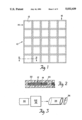
- FIG. 1 is a front view of a panel array of the invention.
- FIG. 2 is a sectional view taken along lines II--II of FIG. 1 of the overall panel array performance.
- FIG. 3 is a schematic view of a first method for forming panel envelopes in accordance with the invention.
- FIG. 4 is a schematic view of a method for forming panels in accordance with the invention.
- FIG. 5 is a partial sectional view of a panel.
- FIG. 6 is a perspective view of a portion of a panel array made in accordance with the FIG. 4 method.
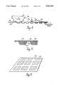
- FIG. 7 is a sectional side view of a first step in an alternate method for making the panels of the invention.
- FIG. 8 is a sectional side view of a last step in the process of FIG. 7.
- FIG. 9 is a sectional view of a first step in another method embodiment for making the panels of the invention.
- FIG. 10 shows the panel as processed in FIG. 9.
- FIG. 11 shows a step in a glass blowing embodiment of the invention.
- FIG. 12 shows the panel envelope as made per FIG. 11.
- Each panel consists of an inner core 18 of low thermal conductivity powder, such as fumed silica (MinileitTM, Gruenzweig and Hartmann AG) (Aerosil 380® or Cab-O-Sil®, Cabot Corporation) silica dust (Selma GrayTM, Alabama Met. Corp.
- fumed silica such as fumed silica (MinileitTM, Gruenzweig and Hartmann AG) (Aerosil 380® or Cab-O-Sil®, Cabot Corporation) silica dust (Selma GrayTM, Alabama Met. Corp.
- each of these materials is considered to be a low conductivity powder.
- such material should have a high thermal resistivity of about 15 or more (h ft 2 °F./Btu in) at pressure levels in the range of 1/10-10 mm Hg.
- An outer envelope 20 of low thermal conductivity material which has a low permeability to atmospheric gases encloses the powder.
- this material is glass, such as pyrex®, C-Glass, Corning low melting point solder glass, or an Owens-Corning Glass fiber mat combined with solder glass or ceramic glaze.
- the envelope is evacuated down to a pressure of about 5 mm Hg.
- Glass has a thermal conductivity which is 200 times less than aluminum, 40 times less than mild steel and only 3-5 times greater than polymers. In addition, glass has a very low permeability to all gases, except helium.
- a glass envelope 20 is formed of a glass film 5-15 thousands of an inch thick.
- Each panel envelope 20 is 5 inches wide and 1 inch thick. This will have an insulating value equivalent to 3.5-4 inch thick closed cell foam.
- the vacuum elements of this width are preferably enclosed in open cell air filled foam protection covering 22.
- the foam 22 protects the glass surface from abrasion or sharp objects. If a 5 inch wide envelope 20 is punctured, neighboring vacuum panels will continue to function and the overall impact on the appliance or the building energy efficiency will be minimal.
- Thin glass sheets for the envelope can be manufactured by continuous extrusion and drawing, as shown in the schematic diagram of FIG. 3.
- Softened or molten glass 30 is forced through die 32 yielding flattened oval- or elliptical-shaped cylindrical extended glass panel envelopes 34.
- glass in tubular form may be heated and drawn to the requisite envelope shape 34.
- Suitable low thermal conductivity powder (not shown) may be co-extruded into the center of the envelope 34, or added later in the process.
- the extended envelope 34 is cut to the desired length (about 18 inches) and evacuated and sealed at the ends. Molded glass or metallic end caps may be used to seal the ends. Optical clarity and uniform thickness are not necessary, so the sheets should be relatively inexpensive.
- the thin glass envelope has some degree of flexibility; the tightly compacted powder can support the glass without breakage if the glass has the same shape as the powder.
- the glass can be preformed as it is manufactured, as shown in FIG. 4.
- a hot glass sheet is conveyed past a die 42 in the direction of arrow 44.
- Die 42 rotates about its axis in the counterclockwise direction indicated by arrow 46.
- Male molds 48 disposed about the latitude and periphery of cylindrical die 42 create dimples 50, or depressions, in sheet 40 as it passes beneath the die 42. These dimples may be several inches in width or diameter, with a depth up to one or several inches.
- Surrounding each depression 50 is a flat portion 52 of the sheet, as shown in FIG. 6.
- the depressions are filled with powder 60, either in loose form, or compressed lightly into the shape of the depression 50. If in loose form, the powder should be compressed after it enters the depression to eliminate any large voids.
- a second flat sheet of glass 54 is placed over the dimpled sheet 90 forming a cover for the depressions.
- the resulting sandwich 60 (FIG. 5) is placed in a vacuum oven (not shown) to evacuate the air from the powder 60 and the two glass sheets 54 and 50 are sealed by fusing the adjacent flat surfaces 52 and 62 at elevated temperatures (FIG. 5).
- an upper glass sheet 70 can be placed over pellets of compressed powder 72 disposed on a lower glass sheet 74, as shown in FIG. 7.
- Each pill or pellet 72 may be three or four inches wide and one-half to one inch thick.
- the sandwich is placed in a vacuum oven (not shown) and the temperature elevated above the glass softening temperature.
- the glass sheet 72 on top flows around the surface of the pill 72, optionally, with the aid of a mold or fixture 76 applying pressure from above, and joins the sheet 74 on the bottom to form a series of closed surfaces around each individual pill 72, as shown in FIG. 8.
- the compressed insulating powder shapes or pills 80 may be coated with a ceramic or glass powder 82, such as C-Glass or Corning low melting point solder glass, whose melting point is lower than the softening point of the insulating powder forming the pill 80.
- the coated shape is heated in a vacuum until the powder on the surface forms a liquid which flows together to form a continuous surface film or glaze 82' to encapsulate the evacuated pill 80' (FIG. 10).
- the glass envelope can be blown into the desired shape much the same way as glass containers are blown by blowing a hot gob of glass 90 into a mold 92 of the desired shape.
- Possible shapes include flat cylinders 94 four inches in diameter and one inch high with an open filling tube 96 on the top. Another shape is the flattened cylinder described in connection with FIG. 3.
- Powder (not shown) is added to the container 94 and the container is evacuated with a filter in the neck 96 to retain the particles. The powder compacts as it is evacuated, or can be compacted by vibration. Several successive fillings will achieve complete filling of the glass shape.
- the filling tube can be sealed by heating and pinching off the tube 96, or by the use of an end cap similar to the base of an incandescent light bulb.
- the evacuated panels can be placed in a foam matrix 22 (FIG. 2), or used by themselves. They can be used to insulate appliances or to form part of an insulated building panel. Another possible use of the vacuum panel is as a night insulation for windows. Strips 2.5 inches wide and 1/4 inch thick may have an R value of 7 (BTU hrft 2 °F.) -1 when evacuated to a level of 10 mm Hg, or less, and sealed by a glass envelope. These strips could be used in the form of jalousies, or in a flexible roll which can be deployed at night.
- the inorganic ceramic envelope evacuated powder panels of the present invention can be made with small widths without causing substantial degradation of thermal performance.
- the powder is enclosed in a five to 10 mil thick nonwoven glass fiber mat, which is porous to air, such as that made by Owens Corning Fiberglas.
- the powder element enclosed in the mat can be used in the aforementioned processes.
- the mat can be impregnated with powdered glass, such as Corning low melting point solder glass or powdered C glass, so that when the mat is heated, the powdered glass melts to form with the mat a strong impermeable envelope.
- the mat and the powdered glass can be combined together before applying around the low conductivity powder, or the low conductivity powder can be encapsulated within the mat, the glass powder applied to the mat surface and the resulting elements placed in a vacuum furnace to evacuate the low conductivity powder and melt the glass powder on the surface of the glass mat.
- the glass powder must have a lower melting point than the softening point of the low conductivity powder.
- the powder may be desirable to first heat the powder in loose or compressed form and/or evacuate the powder for enough time to drive off water, gas or vapor-forming materials which are physically trapped or chemically bonded to the particles before the particles are encapsulated in the glass layer. Typically, heating at 212° F. for 24 hours is used for the powder.
- low temperature means are used to seal the glass around the low conductivity powder
- This process can be carried out using processes similar to the vacuum packing of foods, such as coffee.
- This package could be subsequently sealed in a thin glass envelope within hours or days of its manufacture. In sealing this package in glass film, the evacuation could be carried out very quickly.
Landscapes
- Engineering & Computer Science (AREA)
- Physics & Mathematics (AREA)
- Architecture (AREA)
- General Engineering & Computer Science (AREA)
- Mechanical Engineering (AREA)
- Thermal Sciences (AREA)
- Chemical & Material Sciences (AREA)
- Acoustics & Sound (AREA)
- Combustion & Propulsion (AREA)
- Electromagnetism (AREA)
- Civil Engineering (AREA)
- Structural Engineering (AREA)
- Thermal Insulation (AREA)
- Joining Of Glass To Other Materials (AREA)
Abstract
Thermal insulation vacuum panels are formed of an inner core of compressed low thermal conductivity powders enclosed by a ceramic/glass envelope evaluated to a low pressure.
Description
The Government has rights in this invention pursuant to Subcontract Number 19X-09099C awarded by the Department of Energy.
The most efficient insulation used in buildings and appliances is closed cell foam polyurethane, polyisocyanerate or phenolic insulation. When new, this insulation has over twice the insulating value per inch of thickness as does fiberglass insulation. Substantially, all commercial refrigerators made today in the U.S. use closed cell foam for the surfaces; save the doors. About seven million refrigerators are sold in the U.S. every year. One-third of the interior volume of a refrigerator is foam insulation. Industry representatives estimate that reducing insulation volume by one cubic foot would be worth $50.
About one-half of the buildings constructed in the U.S. use closed cell foam for roof or wall insulation. Use of boards made of foam as exterior sheathing is the most practical way 2×4 framed construction can meet the current energy standards.
Closed cell foam has excellent insulating characteristics because it contains chlorofluorocarbon (CFC) vapor within the cells. The CFC vapor has a thermal conductivity which is one-third that of air. Unfortunately, it has been found that this CFC causes depletion of the stratospheric ozone layer. The U.S. and other developed nations have agreed to phase out the use of CFC over the next decade. Replacement refrigerant vapors are not available at present. Replacements being considered have not completed toxicity tests, have higher projected costs and higher thermal conductivity, and there is little manufacturing capability in place for these replacements.
All of the above factors favor the development of alternate insulations which are inexpensive and have insulating values per unit thickness equal to or exceeding that of present day closed cell foams. One such concept is vacuum thermal insulation. Vacuum insulations have been used for thermos-type containers and for vessels containing cryogenic fluids. These are vacuums made with rigid wall containers which have a high reflectivity surface to reduce radiation heat transfer. These insulations are expensive and fragile.
Recent interest has centered on vacuum panels made with flexible surfaces. In Uekado et al., U.S. Pat No. 4,668,555, the panel is formed of evacuated foam insulation within a metal-plastics laminate film envelope. In another system, the panels are filled with lightly compressed blocks of fine powder. The powder is covered with a flexible plastic skin or packaging coated with thin metallic layers which prevent air diffusion. When the interior of the panel is evacuated to a modest vacuum, e.g., one mm Hg pressure, the effective conductivity of the powder is found to have one-third to one-fifth the conductivity of the best closed cell foam insulation. The powder also supports the skin so that it does not collapse when it is evacuated.
The problem with such systems is the presence of pin holes, or gaps, in the metallic-plastic layers which allow air to enter the panel. As the air pressure in the panel rises, the insulating performance drops off dramatically.
Use of thicker metal foils to prevent pin holes causes a secondary problem. Since the metal is a good conductor of heat, appreciable heat is transferred around the foil surface, bypassing the vacuum space.
The deficiencies summarized above may be overcome by the present invention. In accordance with the present invention, evacuated insulation panels are formed by enclosing in an evacuated envelope lightly compressed fine powder formed of low thermal conductivity materials. The envelope is also comprised of low thermal conductivity, low gas permeable ceramic material, such as glass or other ceramics in continuous layers. Optionally, the panels thus formed may be enclosed in an outer protective enclosure of low thermal conductivity lightweight material, such as open-cell foam.
The low-thermal conductivity envelope reduces the opportunity for heat to bypass the evacuated envelope and the foam enclosure protects the envelope surface from abrasion or sharp objects.
The ceramic envelope can be preformed in the shape of the powder as it is manufactured, or it can initially be in continuous sheet form, powder or non-woven fiber form, or it can be placed over the compressed powder, heated to softening, and formed around the powder by evacuating the powder while the hot film envelope is being formed in place around the powder.
An array of N rows and M columns of such panels can be formed so that damage to one does not substantially degrade overall performance.
FIG. 1 is a front view of a panel array of the invention.
FIG. 2 is a sectional view taken along lines II--II of FIG. 1 of the overall panel array performance.
FIG. 3 is a schematic view of a first method for forming panel envelopes in accordance with the invention.
FIG. 4 is a schematic view of a method for forming panels in accordance with the invention.
FIG. 5 is a partial sectional view of a panel.
FIG. 6 is a perspective view of a portion of a panel array made in accordance with the FIG. 4 method.
FIG. 7 is a sectional side view of a first step in an alternate method for making the panels of the invention.
FIG. 8 is a sectional side view of a last step in the process of FIG. 7.
FIG. 9 is a sectional view of a first step in another method embodiment for making the panels of the invention.
FIG. 10 shows the panel as processed in FIG. 9.
FIG. 11 shows a step in a glass blowing embodiment of the invention.
FIG. 12 shows the panel envelope as made per FIG. 11.
Referring now to FIGS. 1 and 2, the invention will now be described in detail in connection therewith. An array 10 of evacuated insulation panels 12 is shown in FIG. 1 which consists of N rows 14 and M columns 16. In the embodiment of FIG. 1, N=M=5. Each panel consists of an inner core 18 of low thermal conductivity powder, such as fumed silica (Minileit™, Gruenzweig and Hartmann AG) (Aerosil 380® or Cab-O-Sil®, Cabot Corporation) silica dust (Selma Gray™, Alabama Met. Corp. or Beverly Fume™, Interlake, Inc.), fine perlite (Chemrock Corp.), fiberglass and alumina, precipitated silica (FK500LS, Degussa Corp.) or precipitated silica/fly ash mixtures. Each of these materials is considered to be a low conductivity powder. Preferably, such material should have a high thermal resistivity of about 15 or more (h ft2 °F./Btu in) at pressure levels in the range of 1/10-10 mm Hg. [See Advanced Evacuated Thermal Insulators: The State of the Art, H. Alan Fine (1988)] An outer envelope 20 of low thermal conductivity material which has a low permeability to atmospheric gases encloses the powder. Preferably, this material is glass, such as pyrex®, C-Glass, Corning low melting point solder glass, or an Owens-Corning Glass fiber mat combined with solder glass or ceramic glaze.
The envelope is evacuated down to a pressure of about 5 mm Hg.
Glass has a thermal conductivity which is 200 times less than aluminum, 40 times less than mild steel and only 3-5 times greater than polymers. In addition, glass has a very low permeability to all gases, except helium.
In the embodiment of FIG. 1, a glass envelope 20 is formed of a glass film 5-15 thousands of an inch thick. Each panel envelope 20 is 5 inches wide and 1 inch thick. This will have an insulating value equivalent to 3.5-4 inch thick closed cell foam. The vacuum elements of this width are preferably enclosed in open cell air filled foam protection covering 22. The foam 22 protects the glass surface from abrasion or sharp objects. If a 5 inch wide envelope 20 is punctured, neighboring vacuum panels will continue to function and the overall impact on the appliance or the building energy efficiency will be minimal.
Thin glass sheets for the envelope can be manufactured by continuous extrusion and drawing, as shown in the schematic diagram of FIG. 3. Softened or molten glass 30 is forced through die 32 yielding flattened oval- or elliptical-shaped cylindrical extended glass panel envelopes 34. Alternatively, glass in tubular form may be heated and drawn to the requisite envelope shape 34. Suitable low thermal conductivity powder (not shown) may be co-extruded into the center of the envelope 34, or added later in the process. The extended envelope 34 is cut to the desired length (about 18 inches) and evacuated and sealed at the ends. Molded glass or metallic end caps may be used to seal the ends. Optical clarity and uniform thickness are not necessary, so the sheets should be relatively inexpensive.
The thin glass envelope has some degree of flexibility; the tightly compacted powder can support the glass without breakage if the glass has the same shape as the powder. The glass can be preformed as it is manufactured, as shown in FIG. 4. In FIG. 4, a hot glass sheet is conveyed past a die 42 in the direction of arrow 44. Die 42 rotates about its axis in the counterclockwise direction indicated by arrow 46. Male molds 48 disposed about the latitude and periphery of cylindrical die 42 create dimples 50, or depressions, in sheet 40 as it passes beneath the die 42. These dimples may be several inches in width or diameter, with a depth up to one or several inches. Surrounding each depression 50 is a flat portion 52 of the sheet, as shown in FIG. 6. The depressions are filled with powder 60, either in loose form, or compressed lightly into the shape of the depression 50. If in loose form, the powder should be compressed after it enters the depression to eliminate any large voids. A second flat sheet of glass 54 is placed over the dimpled sheet 90 forming a cover for the depressions. The resulting sandwich 60 (FIG. 5) is placed in a vacuum oven (not shown) to evacuate the air from the powder 60 and the two glass sheets 54 and 50 are sealed by fusing the adjacent flat surfaces 52 and 62 at elevated temperatures (FIG. 5).
Alternatively, an upper glass sheet 70 can be placed over pellets of compressed powder 72 disposed on a lower glass sheet 74, as shown in FIG. 7. Each pill or pellet 72 may be three or four inches wide and one-half to one inch thick. The sandwich is placed in a vacuum oven (not shown) and the temperature elevated above the glass softening temperature. The glass sheet 72 on top flows around the surface of the pill 72, optionally, with the aid of a mold or fixture 76 applying pressure from above, and joins the sheet 74 on the bottom to form a series of closed surfaces around each individual pill 72, as shown in FIG. 8.
In another embodiment, shown in FIG. 9, the compressed insulating powder shapes or pills 80 may be coated with a ceramic or glass powder 82, such as C-Glass or Corning low melting point solder glass, whose melting point is lower than the softening point of the insulating powder forming the pill 80. The coated shape is heated in a vacuum until the powder on the surface forms a liquid which flows together to form a continuous surface film or glaze 82' to encapsulate the evacuated pill 80' (FIG. 10).
As shown in FIG. 11, the glass envelope can be blown into the desired shape much the same way as glass containers are blown by blowing a hot gob of glass 90 into a mold 92 of the desired shape. Possible shapes include flat cylinders 94 four inches in diameter and one inch high with an open filling tube 96 on the top. Another shape is the flattened cylinder described in connection with FIG. 3. Powder (not shown) is added to the container 94 and the container is evacuated with a filter in the neck 96 to retain the particles. The powder compacts as it is evacuated, or can be compacted by vibration. Several successive fillings will achieve complete filling of the glass shape. The filling tube can be sealed by heating and pinching off the tube 96, or by the use of an end cap similar to the base of an incandescent light bulb.
The evacuated panels can be placed in a foam matrix 22 (FIG. 2), or used by themselves. They can be used to insulate appliances or to form part of an insulated building panel. Another possible use of the vacuum panel is as a night insulation for windows. Strips 2.5 inches wide and 1/4 inch thick may have an R value of 7 (BTU hrft2 °F.)-1 when evacuated to a level of 10 mm Hg, or less, and sealed by a glass envelope. These strips could be used in the form of jalousies, or in a flexible roll which can be deployed at night.
The inorganic ceramic envelope evacuated powder panels of the present invention can be made with small widths without causing substantial degradation of thermal performance.
In another embodiment, the powder is enclosed in a five to 10 mil thick nonwoven glass fiber mat, which is porous to air, such as that made by Owens Corning Fiberglas. The powder element enclosed in the mat can be used in the aforementioned processes. Alternatively, the mat can be impregnated with powdered glass, such as Corning low melting point solder glass or powdered C glass, so that when the mat is heated, the powdered glass melts to form with the mat a strong impermeable envelope. The mat and the powdered glass can be combined together before applying around the low conductivity powder, or the low conductivity powder can be encapsulated within the mat, the glass powder applied to the mat surface and the resulting elements placed in a vacuum furnace to evacuate the low conductivity powder and melt the glass powder on the surface of the glass mat. In this process, the glass powder must have a lower melting point than the softening point of the low conductivity powder.
To automate the process, it may be desirable to first heat the powder in loose or compressed form and/or evacuate the powder for enough time to drive off water, gas or vapor-forming materials which are physically trapped or chemically bonded to the particles before the particles are encapsulated in the glass layer. Typically, heating at 212° F. for 24 hours is used for the powder.
If low temperature means are used to seal the glass around the low conductivity powder, it may be advantageous to first evacuate and seal the powder in an inexpensive conventional food packaging which will retain an adequate vacuum, of the order of 1 to 10 mm Hg for a period of several hours to several weeks. This process can be carried out using processes similar to the vacuum packing of foods, such as coffee. This package could be subsequently sealed in a thin glass envelope within hours or days of its manufacture. In sealing this package in glass film, the evacuation could be carried out very quickly.
This completes the description of the preferred embodiments of the invention.
Those skilled in the art will recognize, or be able to ascertain employing no more than routine experimentation, many equivalents to the specific structures, steps, functions and materials described specifically herein, and such equivalents are intended to be encompassed within the scope of the following claims.
Claims (6)
1. An evacuated insulation system comprising:
a) a plurality of panels each comprising:
(i) an inner core of low thermal conductivity powder;
(ii) an outer envelope of thin low thermal conductivity, low gas permeable glass material enclosing the powder in an evacuated volume; and
b) a protective covering of closed cell foam enclosing the panels.
2. The system of claim 3 wherein the panels form an array of N rows and M columns of evacuated panels.
3. The system of claim 2 wherein N and M are greater than one.
4. An evacuated insulation system comprising:
a) a plurality of panels each comprising:
(i) an inner core of low thermal conductivity powder;
(ii) an outer envelope of thin low thermal conductivity, low gas permeable ceramic material enclosing the powder in an evacuated volume; and
b) a protective covering of closed cell foam enclosing the panels.
5. The system of claim 4 wherein the panels form an array of N rows and M columns of evacuated panels.
6. The system of claim 5 wherein N and M are greater than one.
Priority Applications (2)
| Application Number | Priority Date | Filing Date | Title |
|---|---|---|---|
| US07/398,788 US5032439A (en) | 1989-08-25 | 1989-08-25 | Thermal insulations using vacuum panels |
| PCT/US1990/004864 WO1991002856A1 (en) | 1989-08-25 | 1990-08-27 | Thermal insulations using vacuum panels |
Applications Claiming Priority (1)
| Application Number | Priority Date | Filing Date | Title |
|---|---|---|---|
| US07/398,788 US5032439A (en) | 1989-08-25 | 1989-08-25 | Thermal insulations using vacuum panels |
Publications (1)
| Publication Number | Publication Date |
|---|---|
| US5032439A true US5032439A (en) | 1991-07-16 |
Family
ID=23576817
Family Applications (1)
| Application Number | Title | Priority Date | Filing Date |
|---|---|---|---|
| US07/398,788 Expired - Fee Related US5032439A (en) | 1989-08-25 | 1989-08-25 | Thermal insulations using vacuum panels |
Country Status (2)
| Country | Link |
|---|---|
| US (1) | US5032439A (en) |
| WO (1) | WO1991002856A1 (en) |
Cited By (40)
| Publication number | Priority date | Publication date | Assignee | Title |
|---|---|---|---|---|
| US5273801A (en) * | 1991-12-31 | 1993-12-28 | Whirlpool Corporation | Thermoformed vacuum insulation container |
| US5316816A (en) * | 1989-05-10 | 1994-05-31 | Degussa Aktiengesellschaft | Form body for heat insulation and vacuum insulation panel with asymmetric design |
| US5330816A (en) * | 1992-12-23 | 1994-07-19 | Owens-Corning Fiberglas Technology Inc. | High R super insulation panel |
| EP0612954A1 (en) * | 1993-02-27 | 1994-08-31 | Fritz Eichenauer GmbH & Co. KG | Preformed compressed composite panel for installation as a thermal insulation in cooking and heating devices |
| US5652278A (en) * | 1993-06-22 | 1997-07-29 | Imperial Chemical Industries Plc | Microvoid polyurethane materials |
| US5792539A (en) * | 1996-07-08 | 1998-08-11 | Oceaneering International, Inc. | Insulation barrier |
| US5877100A (en) * | 1996-09-27 | 1999-03-02 | Cabot Corporation | Compositions and insulation bodies having low thermal conductivity |
| US6010762A (en) * | 1998-01-15 | 2000-01-04 | Cabot Corporation | Self-evacuating vacuum insulation panels |
| US6037033A (en) * | 1996-07-08 | 2000-03-14 | Hunter; Rick Cole | Insulation panel |
| US6132837A (en) * | 1998-09-30 | 2000-10-17 | Cabot Corporation | Vacuum insulation panel and method of preparing the same |
| US6164030A (en) * | 1996-07-29 | 2000-12-26 | Bayer Aktiengesellschaft | Fixed vacuum insulation panel |
| US6220473B1 (en) | 1999-07-14 | 2001-04-24 | Thermo Solutions, Inc. | Collapsible vacuum panel container |
| US6244458B1 (en) * | 1998-07-09 | 2001-06-12 | Thermo Solutions, Inc. | Thermally insulated container |
| WO2002002433A2 (en) * | 2000-07-03 | 2002-01-10 | Kodiak Technologies, Inc. | Thermal container with data monitoring system |
| US6623829B1 (en) * | 1999-04-08 | 2003-09-23 | Free-Flow Packaging International, Inc. | Tear-off cushions of loose fill packing material |
| US20040050021A1 (en) * | 2000-04-27 | 2004-03-18 | Free-Flow Packaging International, Inc. | Cushions of loose fill packing material |
| US6860082B1 (en) * | 1999-04-12 | 2005-03-01 | Isuzu Motors Limited | Heat insulating wall member, and method of manufacturing the same |
| US6964801B1 (en) * | 1997-01-10 | 2005-11-15 | Dana Corporation | Method for producing a heat shield and heat shield produced by this method |
| US20060157274A1 (en) * | 2002-03-22 | 2006-07-20 | Stark David H | Wafer-level hermetic micro-device packages |
| US20060261088A1 (en) * | 2005-05-20 | 2006-11-23 | Qin's, Inc. | Container systems for beverages and other fluids, and associated methods of manufacture and use |
| US20090032924A1 (en) * | 2002-03-22 | 2009-02-05 | Stark David H | Hermetically sealed package with window |
| US20090074997A1 (en) * | 2007-09-14 | 2009-03-19 | Electronics Packaging Solutions, Inc. | Insulating glass unit having multi-height internal standoffs and visible decoration |
| US20090136703A1 (en) * | 2005-06-13 | 2009-05-28 | James Carolan | Insulating panel |
| US20090145092A1 (en) * | 2006-11-17 | 2009-06-11 | Minnesota Thermal Science, Llc | Method of packaging thermally labile goods employing color-coded panels of phase change material |
| US20100034996A1 (en) * | 2008-08-09 | 2010-02-11 | Lawrence Mott | Asymmetrical flexible edge seal for vacuum insulating glass |
| US20100175347A1 (en) * | 2009-01-15 | 2010-07-15 | Bettger Kenneth J | Filament-strung stand-off elements for maintaining pane separation in vacuum insulating glazing units |
| US20100178439A1 (en) * | 2009-01-15 | 2010-07-15 | Eversealed Windows, Inc. | Flexible edge seal for vacuum insulating glazing units |
| US7832177B2 (en) | 2002-03-22 | 2010-11-16 | Electronics Packaging Solutions, Inc. | Insulated glazing units |
| US20100326993A1 (en) * | 2009-02-20 | 2010-12-30 | Mayer William T | Modular cuboidal passive temperature controlled shipping container |
| US7950246B1 (en) * | 2008-02-13 | 2011-05-31 | Minnesota Thermal Science, Llc | Assembly of abutting vacuum insulated panels arranged to form a retention chamber with a slip surface interposed between the panels |
| US20110147391A1 (en) * | 2009-12-17 | 2011-06-23 | Jacob Corder | Cascading series of thermally insulated passive temperature controlled containers |
| US20120009376A1 (en) * | 2010-07-12 | 2012-01-12 | Rusek Jr Stanley J | Vacuum Insulation Panel, Insulated Masonry Structure Comprising Same, And Method Of Construction |
| EP2543942A2 (en) * | 2010-03-04 | 2013-01-09 | LG Hausys, Ltd. | Grooved type of vacuum thermal insulation material and a production method for the same |
| JP2013245775A (en) * | 2012-05-28 | 2013-12-09 | Mitsubishi Electric Corp | Vacuum heat insulating material and vacuum heat insulating device employing the vacuum heat insulating material |
| US8950162B2 (en) | 2010-06-02 | 2015-02-10 | Eversealed Windows, Inc. | Multi-pane glass unit having seal with adhesive and hermetic coating layer |
| US9328512B2 (en) | 2011-05-05 | 2016-05-03 | Eversealed Windows, Inc. | Method and apparatus for an insulating glazing unit and compliant seal for an insulating glazing unit |
| US10593967B2 (en) | 2016-06-30 | 2020-03-17 | Honeywell International Inc. | Modulated thermal conductance thermal enclosure |
| US10683158B2 (en) | 2017-01-26 | 2020-06-16 | Pelican Biothermal, Llc | Protectively framed and covered thermal insulation panel |
| US11549635B2 (en) | 2016-06-30 | 2023-01-10 | Intelligent Energy Limited | Thermal enclosure |
| US11692763B2 (en) | 2020-10-30 | 2023-07-04 | Whirlpool Corporation | Insulation materials for a vacuum insulated structure and methods of forming |
Families Citing this family (7)
| Publication number | Priority date | Publication date | Assignee | Title |
|---|---|---|---|---|
| US5032439A (en) * | 1989-08-25 | 1991-07-16 | Massachusetts Institute Of Technology | Thermal insulations using vacuum panels |
| DE4342673A1 (en) * | 1993-12-15 | 1995-06-22 | Schoeck Bauteile Gmbh | Component for thermal insulation |
| US5527411A (en) * | 1995-03-31 | 1996-06-18 | Owens-Corning Fiberglas Technology, Inc. | Insulating modular panels incorporating vacuum insulation panels and methods for manufacturing |
| US5875599A (en) * | 1995-09-25 | 1999-03-02 | Owens-Corning Fiberglas Technology Inc. | Modular insulation panels and insulated structures |
| FR2755159B1 (en) * | 1996-10-28 | 1999-01-15 | Panhelleux Gerard Marcel Patri | SELF-SUPPORTING INSULATING PANEL |
| AT500367B1 (en) * | 2004-01-09 | 2007-11-15 | Prima Bau Und Daemmsysteme Ges | THERMAL PLATE |
| DE202010009060U1 (en) * | 2010-06-15 | 2010-09-02 | Microtherm N.V. | Thermal insulation composite |
Citations (17)
| Publication number | Priority date | Publication date | Assignee | Title |
|---|---|---|---|---|
| GB1271070A (en) * | 1969-01-22 | 1972-04-19 | Accessair Sa | Evacuated hollow panels and container elements |
| US3991531A (en) * | 1970-06-25 | 1976-11-16 | Otto Alfred Becker | Composite wall element for thermal and acoustic insulation |
| US4159359A (en) * | 1976-08-05 | 1979-06-26 | L'air Liquide Societe Anonyme Pour L'etude Et L'exploitation Des Procedes Georges Claude | Insulating material with low thermal conductivity, formed of a compacted granular structure |
| US4304824A (en) * | 1980-11-10 | 1981-12-08 | Karpinski Ralph E | Flexible modular insulation |
| US4399175A (en) * | 1979-07-16 | 1983-08-16 | Grunzweig + Hartmann Und Glasfaser Ag | Heat-insulating body |
| US4425413A (en) * | 1980-12-06 | 1984-01-10 | Brown, Boveri & Cie Ag | Thermal Insulation |
| US4492725A (en) * | 1982-07-20 | 1985-01-08 | Matsushita Electric Industrial Co., Ltd. | Composite thermal insulator |
| US4505977A (en) * | 1982-03-27 | 1985-03-19 | Brown, Boveri & Cie Ag | Thermal insulation |
| US4529638A (en) * | 1980-12-09 | 1985-07-16 | Matsushita Electric Industrial Co., Ltd. | Thermal insulator |
| US4531511A (en) * | 1983-07-14 | 1985-07-30 | Hochberg Nelson D | Means for controlling heat flux |
| US4579756A (en) * | 1984-08-13 | 1986-04-01 | Edgel Rex D | Insulation material with vacuum compartments |
| US4636415A (en) * | 1985-02-08 | 1987-01-13 | General Electric Company | Precipitated silica insulation |
| US4668555A (en) * | 1984-12-27 | 1987-05-26 | Matsushita Refrigeration Co. | Heat insulating body |
| US4681788A (en) * | 1986-07-31 | 1987-07-21 | General Electric Company | Insulation formed of precipitated silica and fly ash |
| US4683154A (en) * | 1985-08-19 | 1987-07-28 | The United States Of America As Represented By The United States Department Of Energy | Laser sealed vacuum insulation window |
| US4798753A (en) * | 1986-12-19 | 1989-01-17 | General Electric Company | Insulating panels containing insulating powders and insulating gases |
| WO1991002856A1 (en) * | 1989-08-25 | 1991-03-07 | Massachusetts Institute Of Technology | Thermal insulations using vacuum panels |
-
1989
- 1989-08-25 US US07/398,788 patent/US5032439A/en not_active Expired - Fee Related
-
1990
- 1990-08-27 WO PCT/US1990/004864 patent/WO1991002856A1/en unknown
Patent Citations (17)
| Publication number | Priority date | Publication date | Assignee | Title |
|---|---|---|---|---|
| GB1271070A (en) * | 1969-01-22 | 1972-04-19 | Accessair Sa | Evacuated hollow panels and container elements |
| US3991531A (en) * | 1970-06-25 | 1976-11-16 | Otto Alfred Becker | Composite wall element for thermal and acoustic insulation |
| US4159359A (en) * | 1976-08-05 | 1979-06-26 | L'air Liquide Societe Anonyme Pour L'etude Et L'exploitation Des Procedes Georges Claude | Insulating material with low thermal conductivity, formed of a compacted granular structure |
| US4399175A (en) * | 1979-07-16 | 1983-08-16 | Grunzweig + Hartmann Und Glasfaser Ag | Heat-insulating body |
| US4304824A (en) * | 1980-11-10 | 1981-12-08 | Karpinski Ralph E | Flexible modular insulation |
| US4425413A (en) * | 1980-12-06 | 1984-01-10 | Brown, Boveri & Cie Ag | Thermal Insulation |
| US4529638A (en) * | 1980-12-09 | 1985-07-16 | Matsushita Electric Industrial Co., Ltd. | Thermal insulator |
| US4505977A (en) * | 1982-03-27 | 1985-03-19 | Brown, Boveri & Cie Ag | Thermal insulation |
| US4492725A (en) * | 1982-07-20 | 1985-01-08 | Matsushita Electric Industrial Co., Ltd. | Composite thermal insulator |
| US4531511A (en) * | 1983-07-14 | 1985-07-30 | Hochberg Nelson D | Means for controlling heat flux |
| US4579756A (en) * | 1984-08-13 | 1986-04-01 | Edgel Rex D | Insulation material with vacuum compartments |
| US4668555A (en) * | 1984-12-27 | 1987-05-26 | Matsushita Refrigeration Co. | Heat insulating body |
| US4636415A (en) * | 1985-02-08 | 1987-01-13 | General Electric Company | Precipitated silica insulation |
| US4683154A (en) * | 1985-08-19 | 1987-07-28 | The United States Of America As Represented By The United States Department Of Energy | Laser sealed vacuum insulation window |
| US4681788A (en) * | 1986-07-31 | 1987-07-21 | General Electric Company | Insulation formed of precipitated silica and fly ash |
| US4798753A (en) * | 1986-12-19 | 1989-01-17 | General Electric Company | Insulating panels containing insulating powders and insulating gases |
| WO1991002856A1 (en) * | 1989-08-25 | 1991-03-07 | Massachusetts Institute Of Technology | Thermal insulations using vacuum panels |
Non-Patent Citations (8)
| Title |
|---|
| "Advanced Evacuated Thermal Insulations: The State of the Art", by H. Alan Fine, 6/15/88, pp. 1-38. |
| "Development of Advanced Thermal Insulation for Appliances", Progress Report for the Period Jul. 1984 through Jun. 1985, Yarbrough et al., May 1986. |
| "Flat Panel Vacuum Thermal Insulation", Strong et al., Journal of Applied Physics, vol. 31, No. 1, Jan. 1960, pp. 39-50. |
| "The Thermal Resistance of Perlite-Based Evaluated Insulations for Refrigerators", Yarbrough et al., Sep. 1986. |
| Advanced Evacuated Thermal Insulations: The State of the Art , by H. Alan Fine, 6/15/88, pp. 1 38. * |
| Development of Advanced Thermal Insulation for Appliances , Progress Report for the Period Jul. 1984 through Jun. 1985, Yarbrough et al., May 1986. * |
| Flat Panel Vacuum Thermal Insulation , Strong et al., Journal of Applied Physics , vol. 31, No. 1, Jan. 1960, pp. 39 50. * |
| The Thermal Resistance of Perlite Based Evaluated Insulations for Refrigerators , Yarbrough et al., Sep. 1986. * |
Cited By (56)
| Publication number | Priority date | Publication date | Assignee | Title |
|---|---|---|---|---|
| US5316816A (en) * | 1989-05-10 | 1994-05-31 | Degussa Aktiengesellschaft | Form body for heat insulation and vacuum insulation panel with asymmetric design |
| US5273801A (en) * | 1991-12-31 | 1993-12-28 | Whirlpool Corporation | Thermoformed vacuum insulation container |
| US5330816A (en) * | 1992-12-23 | 1994-07-19 | Owens-Corning Fiberglas Technology Inc. | High R super insulation panel |
| EP0612954A1 (en) * | 1993-02-27 | 1994-08-31 | Fritz Eichenauer GmbH & Co. KG | Preformed compressed composite panel for installation as a thermal insulation in cooking and heating devices |
| US5652278A (en) * | 1993-06-22 | 1997-07-29 | Imperial Chemical Industries Plc | Microvoid polyurethane materials |
| US5763502A (en) * | 1993-06-22 | 1998-06-09 | Imperial Chemical Industries Plc | Microvoid polyurethane materials |
| US6001449A (en) * | 1996-07-08 | 1999-12-14 | Oceaneering International, Inc. | Insulation panel with getter material support |
| US6037033A (en) * | 1996-07-08 | 2000-03-14 | Hunter; Rick Cole | Insulation panel |
| US5792539A (en) * | 1996-07-08 | 1998-08-11 | Oceaneering International, Inc. | Insulation barrier |
| US6164030A (en) * | 1996-07-29 | 2000-12-26 | Bayer Aktiengesellschaft | Fixed vacuum insulation panel |
| US5877100A (en) * | 1996-09-27 | 1999-03-02 | Cabot Corporation | Compositions and insulation bodies having low thermal conductivity |
| US6964801B1 (en) * | 1997-01-10 | 2005-11-15 | Dana Corporation | Method for producing a heat shield and heat shield produced by this method |
| US6010762A (en) * | 1998-01-15 | 2000-01-04 | Cabot Corporation | Self-evacuating vacuum insulation panels |
| US6244458B1 (en) * | 1998-07-09 | 2001-06-12 | Thermo Solutions, Inc. | Thermally insulated container |
| US6132837A (en) * | 1998-09-30 | 2000-10-17 | Cabot Corporation | Vacuum insulation panel and method of preparing the same |
| US6623829B1 (en) * | 1999-04-08 | 2003-09-23 | Free-Flow Packaging International, Inc. | Tear-off cushions of loose fill packing material |
| US6860082B1 (en) * | 1999-04-12 | 2005-03-01 | Isuzu Motors Limited | Heat insulating wall member, and method of manufacturing the same |
| US6220473B1 (en) | 1999-07-14 | 2001-04-24 | Thermo Solutions, Inc. | Collapsible vacuum panel container |
| US20040050021A1 (en) * | 2000-04-27 | 2004-03-18 | Free-Flow Packaging International, Inc. | Cushions of loose fill packing material |
| WO2002002433A3 (en) * | 2000-07-03 | 2003-09-04 | Kodiak Technologies Inc | Thermal container with data monitoring system |
| WO2002002433A2 (en) * | 2000-07-03 | 2002-01-10 | Kodiak Technologies, Inc. | Thermal container with data monitoring system |
| US20060157274A1 (en) * | 2002-03-22 | 2006-07-20 | Stark David H | Wafer-level hermetic micro-device packages |
| US20090032924A1 (en) * | 2002-03-22 | 2009-02-05 | Stark David H | Hermetically sealed package with window |
| US7832177B2 (en) | 2002-03-22 | 2010-11-16 | Electronics Packaging Solutions, Inc. | Insulated glazing units |
| US7517712B2 (en) | 2002-03-22 | 2009-04-14 | Electronics Packaging Solutions, Inc. | Wafer-level hermetic micro-device packages |
| US20060261088A1 (en) * | 2005-05-20 | 2006-11-23 | Qin's, Inc. | Container systems for beverages and other fluids, and associated methods of manufacture and use |
| US20090136703A1 (en) * | 2005-06-13 | 2009-05-28 | James Carolan | Insulating panel |
| US20110195218A1 (en) * | 2005-06-13 | 2011-08-11 | Kingspan Research And Developments Limited | Insulating Panel |
| US20090145092A1 (en) * | 2006-11-17 | 2009-06-11 | Minnesota Thermal Science, Llc | Method of packaging thermally labile goods employing color-coded panels of phase change material |
| US7905075B2 (en) | 2006-11-17 | 2011-03-15 | Minnesota Thermal Science, Llc | Method of packaging thermally labile goods employing color-coded panels of phase change material |
| US7989040B2 (en) | 2007-09-14 | 2011-08-02 | Electronics Packaging Solutions, Inc. | Insulating glass unit having multi-height internal standoffs and visible decoration |
| US20090074997A1 (en) * | 2007-09-14 | 2009-03-19 | Electronics Packaging Solutions, Inc. | Insulating glass unit having multi-height internal standoffs and visible decoration |
| US7950246B1 (en) * | 2008-02-13 | 2011-05-31 | Minnesota Thermal Science, Llc | Assembly of abutting vacuum insulated panels arranged to form a retention chamber with a slip surface interposed between the panels |
| US20100034996A1 (en) * | 2008-08-09 | 2010-02-11 | Lawrence Mott | Asymmetrical flexible edge seal for vacuum insulating glass |
| US8283023B2 (en) | 2008-08-09 | 2012-10-09 | Eversealed Windows, Inc. | Asymmetrical flexible edge seal for vacuum insulating glass |
| US8512830B2 (en) | 2009-01-15 | 2013-08-20 | Eversealed Windows, Inc. | Filament-strung stand-off elements for maintaining pane separation in vacuum insulating glazing units |
| US20100178439A1 (en) * | 2009-01-15 | 2010-07-15 | Eversealed Windows, Inc. | Flexible edge seal for vacuum insulating glazing units |
| US20100175347A1 (en) * | 2009-01-15 | 2010-07-15 | Bettger Kenneth J | Filament-strung stand-off elements for maintaining pane separation in vacuum insulating glazing units |
| US8329267B2 (en) | 2009-01-15 | 2012-12-11 | Eversealed Windows, Inc. | Flexible edge seal for vacuum insulating glazing units |
| US9751682B2 (en) | 2009-02-20 | 2017-09-05 | Pelican Biothermal Llc | Modular cuboidal passive temperature controlled shipping container |
| US20100326993A1 (en) * | 2009-02-20 | 2010-12-30 | Mayer William T | Modular cuboidal passive temperature controlled shipping container |
| US8424335B2 (en) | 2009-12-17 | 2013-04-23 | Minnesota Thermal Science, Llc | Cascading series of thermally insulated passive temperature controlled containers |
| US20110147391A1 (en) * | 2009-12-17 | 2011-06-23 | Jacob Corder | Cascading series of thermally insulated passive temperature controlled containers |
| EP2543942A2 (en) * | 2010-03-04 | 2013-01-09 | LG Hausys, Ltd. | Grooved type of vacuum thermal insulation material and a production method for the same |
| EP2543942A4 (en) * | 2010-03-04 | 2014-10-22 | Lg Hausys Ltd | Grooved type of vacuum thermal insulation material and a production method for the same |
| US8927084B2 (en) | 2010-03-04 | 2015-01-06 | Lg Hausys, Ltd. | Grooved type vacuum thermal insulation material and a production method for the same |
| US8950162B2 (en) | 2010-06-02 | 2015-02-10 | Eversealed Windows, Inc. | Multi-pane glass unit having seal with adhesive and hermetic coating layer |
| US20120009376A1 (en) * | 2010-07-12 | 2012-01-12 | Rusek Jr Stanley J | Vacuum Insulation Panel, Insulated Masonry Structure Comprising Same, And Method Of Construction |
| US11035168B2 (en) | 2011-05-05 | 2021-06-15 | Astravac Glass, Inc. | Method and apparatus for an insulating glazing unit and compliant seal for an insulating glazing unit |
| US9328512B2 (en) | 2011-05-05 | 2016-05-03 | Eversealed Windows, Inc. | Method and apparatus for an insulating glazing unit and compliant seal for an insulating glazing unit |
| JP2013245775A (en) * | 2012-05-28 | 2013-12-09 | Mitsubishi Electric Corp | Vacuum heat insulating material and vacuum heat insulating device employing the vacuum heat insulating material |
| US10593967B2 (en) | 2016-06-30 | 2020-03-17 | Honeywell International Inc. | Modulated thermal conductance thermal enclosure |
| US11223054B2 (en) | 2016-06-30 | 2022-01-11 | Honeywell International Inc. | Modulated thermal conductance thermal enclosure |
| US11549635B2 (en) | 2016-06-30 | 2023-01-10 | Intelligent Energy Limited | Thermal enclosure |
| US10683158B2 (en) | 2017-01-26 | 2020-06-16 | Pelican Biothermal, Llc | Protectively framed and covered thermal insulation panel |
| US11692763B2 (en) | 2020-10-30 | 2023-07-04 | Whirlpool Corporation | Insulation materials for a vacuum insulated structure and methods of forming |
Also Published As
| Publication number | Publication date |
|---|---|
| WO1991002856A1 (en) | 1991-03-07 |
Similar Documents
| Publication | Publication Date | Title |
|---|---|---|
| US5032439A (en) | Thermal insulations using vacuum panels | |
| US6001449A (en) | Insulation panel with getter material support | |
| US6037033A (en) | Insulation panel | |
| EP0535147B1 (en) | Improved compact vacuum insulation | |
| US5798154A (en) | Flex wrapped vacuum insulator | |
| DK173447B1 (en) | Heat-insulating construction or lighting element, process for production thereof and apparatus for implementing the process | |
| US5175975A (en) | Compact vacuum insulation | |
| US5107649A (en) | Compact vacuum insulation embodiments | |
| KR930002589B1 (en) | Vacuum insulation panel | |
| US4636416A (en) | Shaped microporous thermal insulation body with sheathing and process for making same | |
| JP3212309B2 (en) | High insulation panel | |
| FI104651B (en) | Thermal insulation piece for thermal insulation | |
| CA1127395A (en) | Fire screening glazing panels and method of manufacturing same | |
| CA1328724C (en) | Compact vacuum insulation | |
| US4513041A (en) | Tubular vacuum-tight enclosures for thermal and acoustical insulating panels | |
| KR20110028423A (en) | Vacuum insulation panel | |
| GB2115602A (en) | Getters in infra-red radiation detectors | |
| JPH10297944A (en) | Plural layer glass panel | |
| WO1994024398A1 (en) | Insulating panel | |
| EP1337722B1 (en) | Improved edge insulation for vacuum insulation panels | |
| JPS59146993A (en) | Manufacture of heat insulative structure | |
| JPH10306658A (en) | Double glazing panel | |
| JPS6319787B2 (en) | ||
| KR101414515B1 (en) | Vacuum Thermal Insulator Made of a Formed Glass Wool Material and its Fabrication Method | |
| JPH10331532A (en) | Manufacture of low-pressure double glazing |
Legal Events
| Date | Code | Title | Description |
|---|---|---|---|
| AS | Assignment |
Owner name: MASSACHUSETTS INSTITUTE OF TECHNOLOGY, MASSACHUSET Free format text: ASSIGNMENT OF ASSIGNORS INTEREST.;ASSIGNORS:GLICKSMAN, LEON R.;BURKE, MELISSA S.;REEL/FRAME:005117/0564 Effective date: 19890825 |
|
| FEPP | Fee payment procedure |
Free format text: PAYOR NUMBER ASSIGNED (ORIGINAL EVENT CODE: ASPN); ENTITY STATUS OF PATENT OWNER: SMALL ENTITY |
|
| REMI | Maintenance fee reminder mailed | ||
| FPAY | Fee payment |
Year of fee payment: 4 |
|
| SULP | Surcharge for late payment | ||
| REMI | Maintenance fee reminder mailed | ||
| LAPS | Lapse for failure to pay maintenance fees | ||
| FP | Lapsed due to failure to pay maintenance fee |
Effective date: 19990716 |
|
| STCH | Information on status: patent discontinuation |
Free format text: PATENT EXPIRED DUE TO NONPAYMENT OF MAINTENANCE FEES UNDER 37 CFR 1.362 |