US5030875A - Sacrificial quartz crystal mount - Google Patents
Sacrificial quartz crystal mount Download PDFInfo
- Publication number
- US5030875A US5030875A US07/470,484 US47048490A US5030875A US 5030875 A US5030875 A US 5030875A US 47048490 A US47048490 A US 47048490A US 5030875 A US5030875 A US 5030875A
- Authority
- US
- United States
- Prior art keywords
- crystal resonator
- crystal
- thermal expansion
- mounting
- resonator
- Prior art date
- Legal status (The legal status is an assumption and is not a legal conclusion. Google has not performed a legal analysis and makes no representation as to the accuracy of the status listed.)
- Expired - Fee Related
Links
Images
Classifications
-
- H—ELECTRICITY
- H03—ELECTRONIC CIRCUITRY
- H03H—IMPEDANCE NETWORKS, e.g. RESONANT CIRCUITS; RESONATORS
- H03H9/00—Networks comprising electromechanical or electro-acoustic devices; Electromechanical resonators
- H03H9/02—Details
- H03H9/05—Holders; Supports
- H03H9/0504—Holders; Supports for bulk acoustic wave devices
- H03H9/0509—Holders; Supports for bulk acoustic wave devices consisting of adhesive elements
-
- H—ELECTRICITY
- H03—ELECTRONIC CIRCUITRY
- H03H—IMPEDANCE NETWORKS, e.g. RESONANT CIRCUITS; RESONATORS
- H03H9/00—Networks comprising electromechanical or electro-acoustic devices; Electromechanical resonators
- H03H9/02—Details
- H03H9/05—Holders; Supports
- H03H9/0504—Holders; Supports for bulk acoustic wave devices
- H03H9/0514—Holders; Supports for bulk acoustic wave devices consisting of mounting pads or bumps
Definitions
- This invention relates to crystal mounting structures.
- this invention relates to crystal mounting structures that reduce mechanical stresses in a piezoelectric quartz crystal resonator.
- FIG. 1 shows a representative cross-sectional diagram of a typical prior art piezoelectric quartz crystal resonator (10).
- a package base (20) which is typically metallic but may also be glass or ceramic, supports a piezoelectric quartz resonator element (30) which includes two electroded surfaces (the electrodes are shown as elements 32 and 34) supported between two fixed mounting posts (36) as shown.
- the piezoelectric quartz crystal resonator (10) includes a thin piece of quartz (30), typically only a few thousandths of an inch thickness having a predetermined cut orientation (such as an AT-cut or GT-cut as they are known in the art).
- the cut orientation, and other physical dimensions and the electrode dimension establish the resonant frequency of the resonator (10).
- the piezoelectric quartz resonator element (30) typically has a thermal expansion coefficient of anywhere between 5 and 30 parts per million per degree centigrade although values between 10 and 20 parts per million per degree centigrade are more typical.
- the package base (20) on the other hand, which is typically metallic, has a thermal expansion coefficient of between 2 and 10 parts per million per degree centigrade.
- the electrodes (32 and 34) on the quartz crystal plate (30) are attached to the mounting posts (36) by an appropriate adhesive.
- Conductive epoxy or solder may be used to attach the mounting posts (36) to the electrodes (32 and 34).
- the quartz crystal resonator (10) usually must be heated to an elevated temperature.
- the package base and quartz crystal plate expand, albeit at different rates and when cooled after the adhesive sets, the mechanical joints existing between the mounting posts create mechanical stresses in the quartz (30) because of the differences in thermal expansion coefficients. Since the thermal expansion coefficients of the package base (20) and the quartz crystal plate (30) are different, the physical dimensions of the pieces will change as their temperature shifts.
- Alternate schemes of mounting the quartz crystal resonator (30) to a package base (20) include using a quartz material for the package base (20) which would have a substantially identical thermal expansion coefficient.
- the cost of using quartz for the package base creates other problems including expense and hermetically sealing the crystal resonator (10).
- a crystal mounting structure which reduces mechanical stresses on the piezoelectric quartz crystal resonator at a reasonable cost would be an improvement over the prior art.
- a crystal resonator that has a piezoelectric quartz crystal plate suspended from the package base by cantilevered mounting posts fixed to the base.
- the crystal resonator includes an intermediate layer of material, preferably similar in size and material to the crystal plate, which is also fixed to the mounting posts, between the crystal plate and package base.
- the intermediate layer is attached to the mounting posts between the package base and crystal plate, it isolates the crystal plate from mechanical stresses caused by differences in thermal expansion coefficients by fixing the position of the mounting posts with respect to the crystal plate and absorbing mechanical stresses that the crystal plate would previously have to absorb.
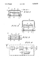
- FIG. 1 shows a representative cross-sectional diagram of a prior art crystal resonator.
- FIG. 2 shows a cross-sectional diagram of a preferred embodiment of the invention.
- FIG. 3 shows an alternate embodiment of the invention.
- FIG. 4 shows a partial block diagram of a communications device or radio that might use a quartz crystal resonator as shown in FIGS. 2 and 3.
- FIG. 2 shows a cross-sectional diagram of the preferred embodiment of the quartz crystal resonator (10) that uses a sacrificial quartz layer (40).
- a package base (20) with a first thermal expansion coefficient supports an electroded piezoelectric quartz crystal plate (30) (also referred to as the active plate (30)).
- the active plate includes (30) electrodes (32 and 34) to which are applied electrical signals that cause the active plate (30) to vibrate at some frequency.
- the vibration frequency of the active plate (30) will be affected by the geometry of the plate, the thickness of the electrodes, the atmosphere surrounding the plate, and other factors.
- Electrical signals are usually carried to the electrodes (32 and 34) through the two vertically oriented cantilevered mounting posts (36), which also support the plate (30) mounted to the package base (20) through feed through holes (38).
- the mounting posts (36) in an alternate embodiment detailed below and shown in FIG. 3 would include beads or dollops of conductive adhesive.
- Electrical signals might also be carried to the electrodes using wires.
- the package base (20) in the preferred embodiment is ceramic but could be glass, metal, or other suitable material. Ceramic package bases (20) are known to have a thermal expansion coefficient of between 6 and 10 parts per million per degree centigrade.
- the active electroded piezoelectric quartz crystal plate (30) typically has a thermal expansion coefficient of approximately 10 to 20 parts per million per degree centigrade.
- the active plate (30) is typically a quartz crystal plate with a predetermined crystal cut orientation (GT-cut or AT-cut for example).
- the sacrificial layer will typically have a cut orientation matched to that of the active layer however alternate crystal cuts may be used for the sacrificial layer (40) as economies of the crystal resonator and operating characteristics of the resonator (10) may dictate.
- These alternate sacrificial layers would typically have preselected physical dimensions (including thickness, length and width).
- the sacrificial layer of quartz (40) (which is the intermediate layer in the crystal resonator (10)) is also fixed to the mounting posts (36) but is between the active plate (30) and the package base (20).
- the sacrificial quartz intermediate layer (40) is preferably quartz crystal having similar dimensions of the quartz crystal plate (30) and preferably with an identical crystal cut orientation such that the mechanical behavior of the sacrificial quartz layer (40) over temperature is substantially identical to the behavior of the active electroded piezoelectric quartz crystal plate (30).
- Alternate sacrificial layers could include any material with a thermal expansion coefficient between those of the active plate (30) and the package base (20) so as to mitigate stress on the active plate over temperature ranges and with physical dimensions to optimally isolate the active plate (30) from the package base (20).
- the quartz crystal layer (30) and the sacrificial layer (40) may be attached using solder, beads of conductive glass, conductive epoxy, or other appropriate adhesive suitable for the frequency of operation, the crystal cut orientation, and the dimensions of the quartz layers.
- Alternate embodiments of the invention could include using mounting posts (36) which are conductive epoxy, conductive adhesive with sufficient rigidity to support the sacrificial layer (40) and the active layer (30), solder, or conductive glass, for example.
- the mounting posts (36) shown in FIG. 2 could be fabricated from any of these alternate materials.
- the mounting post and the adhesive used to attach the mounting post to the electrodes (32) and (34) on the active quartz crystal layer (30) are a convenient apparatus for conducting electrical signals into and out of the crystal resonator (10).
- An alternate embodiment would include the use of small wires attached to the electrodes (32 and 34) on the active plate and to conductive feed-throughs on the package base.
- a mounting hood (50) is usually attached to the package base (20) so that the crystal resonator (10) can be hermetically sealed to protect it from environmental changes.
- FIG. 3 An alternate embodiment of the crystal resonator (10) is shown in FIG. 3.
- the intermediate layer (40) is shown attached to the active plate (30) and to the package base (20) using a conductive glass bead (35), for example, or a bead of conductive epoxy.
- the principal differentiation between the embodiment shown in FIG. 2 and FIG. 3 is the relative spacing between the sacrificial layer (40) and the active layer (30).
- the hermetically sealed crystal mount hood (50) is deleted from FIG. 3 for clarity.)
- FIG. 4 shows a typical application for the crystal resonator (10) shown in FIGS. 2 and 3.
- FIG. 4 an illustrative block diagram of a radio receiver is shown, although those skilled in the art will recognize that more elegant architectures would typically be used today.
- a band-pass filter (6) filters signals from an antenna (1) which are then amplified (7) as shown.
- the output of the first amplifier (7) is also band pass filtered (8) before the signals are coupled into a first mixer stage (9).
- An oscillator (11) which might also be a synthesizer, uses a crystal resonator (10) (schematically shown in this figure but would be constructed as shown in FIGS. 2 and 3) provides a signal to the mixer (9) that yields a first IF frequency as shown.
- the first IF signal may be subsequently processed (digitally or using analog techniques), demodulated, and produced for a speaker (13) by another amplifier stage (12).
- the crystal resonator (10) used in the radio receiver communications device shown in FIG. 4 might be used in other communications devices as well, such as in a radio transmitter or paging device.
- the resonators (10) shown in FIGS. 2 and 3 could be either leaded packages and used with conventional circuit boards or surface mountable packages.
- the thermal stability of the crystal resonator (10) is improved by the addition of the intermediate layer (40) by buffering the active layer (30) from mechanical stresses that would be created by differences in the thermal expansion coefficient of the active layer (30) and the package base (20).
- the structures shown in FIGS. 2 and 3 can be economically manufactured and provide improved performance over wide temperature ranges by virtue of the intermediate sacrificial quartz layer (40).
Abstract
Description
Claims (16)
Priority Applications (1)
| Application Number | Priority Date | Filing Date | Title |
|---|---|---|---|
| US07/470,484 US5030875A (en) | 1990-01-26 | 1990-01-26 | Sacrificial quartz crystal mount |
Applications Claiming Priority (1)
| Application Number | Priority Date | Filing Date | Title |
|---|---|---|---|
| US07/470,484 US5030875A (en) | 1990-01-26 | 1990-01-26 | Sacrificial quartz crystal mount |
Publications (1)
| Publication Number | Publication Date |
|---|---|
| US5030875A true US5030875A (en) | 1991-07-09 |
Family
ID=23867804
Family Applications (1)
| Application Number | Title | Priority Date | Filing Date |
|---|---|---|---|
| US07/470,484 Expired - Fee Related US5030875A (en) | 1990-01-26 | 1990-01-26 | Sacrificial quartz crystal mount |
Country Status (1)
| Country | Link |
|---|---|
| US (1) | US5030875A (en) |
Cited By (15)
| Publication number | Priority date | Publication date | Assignee | Title |
|---|---|---|---|---|
| US5130600A (en) * | 1989-06-02 | 1992-07-14 | Mitsubishi Petrochemical Co., Ltd. | Acceleration sensor |
| US5250870A (en) * | 1992-03-25 | 1993-10-05 | Motorola, Inc. | Ultra-thin surface mount crystal package |
| US5313371A (en) * | 1991-03-04 | 1994-05-17 | Motorola, Inc. | Shielding apparatus for non-conductive electronic circuit packages |
| US5650759A (en) * | 1995-11-09 | 1997-07-22 | Hittman Materials & Medical Components, Inc. | Filtered feedthrough assembly having a mounted chip capacitor for medical implantable devices and method of manufacture therefor |
| US5712523A (en) * | 1995-01-11 | 1998-01-27 | Murata Manufacturing Co., Ltd. | Surface acoustic wave device |
| US5945774A (en) * | 1997-03-28 | 1999-08-31 | Industrial Technology Research Institute | Open package for crystal oscillator chips |
| US6003390A (en) * | 1996-07-17 | 1999-12-21 | Legrand | Tactile sensor, in particular for electrical equipment |
| WO2000008694A1 (en) * | 1998-08-03 | 2000-02-17 | Cts Corporation | Embedded piezoelectric resonator |
| US6236145B1 (en) * | 2000-02-29 | 2001-05-22 | Cts Corporation | High thermal resistivity crystal resonator support structure and oscillator package |
| US6307300B1 (en) * | 1998-06-11 | 2001-10-23 | Murata Manufacturing Co., Ltd | Piezoelectric acoustic component |
| US20040000844A1 (en) * | 2002-06-28 | 2004-01-01 | Morley Peter E. | Low profile temperature-compensated low-stress crystal mount structure |
| US20080265717A1 (en) * | 2005-04-18 | 2008-10-30 | Minoru Iizuka | Piezoelectric Resonator Plate and Piezoelectric Resonator Device |
| US20100123369A1 (en) * | 2008-11-17 | 2010-05-20 | Nihon Dempa Kogyo Co., Ltd | Piezoelectric devices and methods for manufacturing same |
| WO2010085743A2 (en) | 2009-01-26 | 2010-07-29 | Cymatics Laboratories Corporation | Protected resonator |
| RU167515U1 (en) * | 2016-05-20 | 2017-01-10 | Акционерное общество "Морион" | QUARTZ RESONATOR-THERMOSTAT |
Citations (11)
| Publication number | Priority date | Publication date | Assignee | Title |
|---|---|---|---|---|
| US3046423A (en) * | 1958-10-09 | 1962-07-24 | Bliley Electric Company | High shock and vibration resistant piezoelectric crystal units |
| US3754153A (en) * | 1971-12-02 | 1973-08-21 | Bulova Watch Co Inc | Crystal mounting assembly |
| US3805098A (en) * | 1971-12-02 | 1974-04-16 | Bulova Watch Co Inc | Quartz-crystal mounting assembly |
| US3876891A (en) * | 1970-08-14 | 1975-04-08 | Peter Schubotz | Mounting for rod-like crystal oscillators |
| US3906260A (en) * | 1971-09-22 | 1975-09-16 | Suwa Seikosha Kk | Crystal vibrator |
| US4266157A (en) * | 1979-05-18 | 1981-05-05 | The United States Of America As Represented By The Secretary Of The Army | Piezoelectric resonator assembly with thin molybdenum mounting clips |
| US4317059A (en) * | 1978-10-09 | 1982-02-23 | Etat Francais | Acceleration and temperature compensated piezoelectric bi-resonator |
| US4418299A (en) * | 1977-01-12 | 1983-11-29 | Kabushiki Kaisha Suwa Seikosha | Face-shear mode quartz crystal vibrators and method of manufacture |
| US4608510A (en) * | 1981-01-15 | 1986-08-26 | Asulab S.A. - ESA 55 | Piezoelectric micro-resonateur |
| JPS61202509A (en) * | 1985-03-06 | 1986-09-08 | Matsushima Kogyo Co Ltd | Piezoelectric vibrator |
| US4626732A (en) * | 1984-03-30 | 1986-12-02 | Compagnie D'electronique Et De Piezo-Electricite C.E.P.E. | Piezoelectric resonator |
-
1990
- 1990-01-26 US US07/470,484 patent/US5030875A/en not_active Expired - Fee Related
Patent Citations (11)
| Publication number | Priority date | Publication date | Assignee | Title |
|---|---|---|---|---|
| US3046423A (en) * | 1958-10-09 | 1962-07-24 | Bliley Electric Company | High shock and vibration resistant piezoelectric crystal units |
| US3876891A (en) * | 1970-08-14 | 1975-04-08 | Peter Schubotz | Mounting for rod-like crystal oscillators |
| US3906260A (en) * | 1971-09-22 | 1975-09-16 | Suwa Seikosha Kk | Crystal vibrator |
| US3754153A (en) * | 1971-12-02 | 1973-08-21 | Bulova Watch Co Inc | Crystal mounting assembly |
| US3805098A (en) * | 1971-12-02 | 1974-04-16 | Bulova Watch Co Inc | Quartz-crystal mounting assembly |
| US4418299A (en) * | 1977-01-12 | 1983-11-29 | Kabushiki Kaisha Suwa Seikosha | Face-shear mode quartz crystal vibrators and method of manufacture |
| US4317059A (en) * | 1978-10-09 | 1982-02-23 | Etat Francais | Acceleration and temperature compensated piezoelectric bi-resonator |
| US4266157A (en) * | 1979-05-18 | 1981-05-05 | The United States Of America As Represented By The Secretary Of The Army | Piezoelectric resonator assembly with thin molybdenum mounting clips |
| US4608510A (en) * | 1981-01-15 | 1986-08-26 | Asulab S.A. - ESA 55 | Piezoelectric micro-resonateur |
| US4626732A (en) * | 1984-03-30 | 1986-12-02 | Compagnie D'electronique Et De Piezo-Electricite C.E.P.E. | Piezoelectric resonator |
| JPS61202509A (en) * | 1985-03-06 | 1986-09-08 | Matsushima Kogyo Co Ltd | Piezoelectric vibrator |
Cited By (20)
| Publication number | Priority date | Publication date | Assignee | Title |
|---|---|---|---|---|
| US5130600A (en) * | 1989-06-02 | 1992-07-14 | Mitsubishi Petrochemical Co., Ltd. | Acceleration sensor |
| US5313371A (en) * | 1991-03-04 | 1994-05-17 | Motorola, Inc. | Shielding apparatus for non-conductive electronic circuit packages |
| US5250870A (en) * | 1992-03-25 | 1993-10-05 | Motorola, Inc. | Ultra-thin surface mount crystal package |
| US5712523A (en) * | 1995-01-11 | 1998-01-27 | Murata Manufacturing Co., Ltd. | Surface acoustic wave device |
| US5650759A (en) * | 1995-11-09 | 1997-07-22 | Hittman Materials & Medical Components, Inc. | Filtered feedthrough assembly having a mounted chip capacitor for medical implantable devices and method of manufacture therefor |
| US6003390A (en) * | 1996-07-17 | 1999-12-21 | Legrand | Tactile sensor, in particular for electrical equipment |
| US5945774A (en) * | 1997-03-28 | 1999-08-31 | Industrial Technology Research Institute | Open package for crystal oscillator chips |
| US6307300B1 (en) * | 1998-06-11 | 2001-10-23 | Murata Manufacturing Co., Ltd | Piezoelectric acoustic component |
| US6093997A (en) * | 1998-08-03 | 2000-07-25 | Cts Corporation | Embedded piezoelectric resonator |
| WO2000008694A1 (en) * | 1998-08-03 | 2000-02-17 | Cts Corporation | Embedded piezoelectric resonator |
| US6236145B1 (en) * | 2000-02-29 | 2001-05-22 | Cts Corporation | High thermal resistivity crystal resonator support structure and oscillator package |
| US20040000844A1 (en) * | 2002-06-28 | 2004-01-01 | Morley Peter E. | Low profile temperature-compensated low-stress crystal mount structure |
| WO2004004117A2 (en) * | 2002-06-28 | 2004-01-08 | Vectron International | Low profile temperature-compensated low-stress crystal mount structure |
| WO2004004117A3 (en) * | 2002-06-28 | 2004-06-17 | Vectron Internat | Low profile temperature-compensated low-stress crystal mount structure |
| US20080265717A1 (en) * | 2005-04-18 | 2008-10-30 | Minoru Iizuka | Piezoelectric Resonator Plate and Piezoelectric Resonator Device |
| US8004157B2 (en) * | 2005-04-18 | 2011-08-23 | Daishinku Corporation | Piezoelectric resonator plate and piezoelectric resonator device |
| US20100123369A1 (en) * | 2008-11-17 | 2010-05-20 | Nihon Dempa Kogyo Co., Ltd | Piezoelectric devices and methods for manufacturing same |
| US8541929B2 (en) * | 2008-11-17 | 2013-09-24 | Nihon Dempa Kogyo Co., Ltd. | Piezoelectric devices and methods for manufacturing same |
| WO2010085743A2 (en) | 2009-01-26 | 2010-07-29 | Cymatics Laboratories Corporation | Protected resonator |
| RU167515U1 (en) * | 2016-05-20 | 2017-01-10 | Акционерное общество "Морион" | QUARTZ RESONATOR-THERMOSTAT |
Similar Documents
| Publication | Publication Date | Title |
|---|---|---|
| US5030875A (en) | Sacrificial quartz crystal mount | |
| US6111480A (en) | Piezoelectric resonator and method of adjusting resonant frequency thereof | |
| US3339091A (en) | Crystal resonators | |
| KR20120135058A (en) | Piezoelectric vibration element, manufacturing method for piezoelectric vibration element, piezoelectric vibrator, electronic device and electronic apparatus | |
| US20020089261A1 (en) | Surface mount quartz crystal resonators and methods for making same | |
| JPH09326667A (en) | Piezoelectric vibrator element piece | |
| JP2000278079A (en) | Piezoelectric device | |
| WO1992019043A1 (en) | Surface mountable piezoelectric device with in situ finish plate mask | |
| JPH0514442B2 (en) | ||
| US5304887A (en) | Crystal resonator device | |
| US6054793A (en) | Piezoelectric resonator method for adjusting frequency of piezoelectric resonator and communication apparatus including piezoelectric resonator | |
| JP3102869B2 (en) | Structure of ultra-thin piezoelectric resonator | |
| JPS6141215A (en) | Crystal resonator | |
| USRE26707E (en) | Crystal resonators | |
| JPH09326657A (en) | Production of piezoelectric vibrator | |
| JPH08162891A (en) | Surface mount type piezoelectric vibrator | |
| JPH10284975A (en) | Package of surface mounting-type piezoelectric device | |
| JP3164890B2 (en) | Quartz crystal resonator and its manufacturing method | |
| JP3017753B2 (en) | Composite piezoelectric element | |
| JP2929107B2 (en) | Manufacturing method of crystal unit | |
| JPH10117120A (en) | Gt-cut crystal oscillator | |
| JPH0727693Y2 (en) | Quartz crystal support structure | |
| JP2003133886A (en) | Crystal oscillator | |
| JPH08204490A (en) | Surface mounted type electronic component | |
| JP2595933Y2 (en) | Piezoelectric vibrator |
Legal Events
| Date | Code | Title | Description |
|---|---|---|---|
| AS | Assignment |
Owner name: MOTOROLA, INC., SCHAUMBURG, IL A CORP. OF DE Free format text: ASSIGNMENT OF ASSIGNORS INTEREST.;ASSIGNOR:KNECHT, THOMAS A.;REEL/FRAME:005222/0233 Effective date: 19900123 |
|
| FPAY | Fee payment |
Year of fee payment: 4 |
|
| FPAY | Fee payment |
Year of fee payment: 8 |
|
| AS | Assignment |
Owner name: CTS CORPORATION, INDIANA Free format text: ASSIGNMENT OF ASSIGNORS INTEREST;ASSIGNOR:MOTOROLA, INC., A CORPORATION OF DELAWARE;REEL/FRAME:009808/0378 Effective date: 19990226 |
|
| FEPP | Fee payment procedure |
Free format text: PAYOR NUMBER ASSIGNED (ORIGINAL EVENT CODE: ASPN); ENTITY STATUS OF PATENT OWNER: LARGE ENTITY |
|
| REMI | Maintenance fee reminder mailed | ||
| LAPS | Lapse for failure to pay maintenance fees | ||
| STCH | Information on status: patent discontinuation |
Free format text: PATENT EXPIRED DUE TO NONPAYMENT OF MAINTENANCE FEES UNDER 37 CFR 1.362 |
|
| FP | Lapsed due to failure to pay maintenance fee |
Effective date: 20030709 |