US4945404A - Video communication system and phase or frequency modulator included therein - Google Patents
Video communication system and phase or frequency modulator included therein Download PDFInfo
- Publication number
- US4945404A US4945404A US07/191,103 US19110388A US4945404A US 4945404 A US4945404 A US 4945404A US 19110388 A US19110388 A US 19110388A US 4945404 A US4945404 A US 4945404A
- Authority
- US
- United States
- Prior art keywords
- wave
- pixel
- carrier
- modulator
- square
- Prior art date
- Legal status (The legal status is an assumption and is not a legal conclusion. Google has not performed a legal analysis and makes no representation as to the accuracy of the status listed.)
- Expired - Fee Related
Links
Images


Classifications
-
- H—ELECTRICITY
- H04—ELECTRIC COMMUNICATION TECHNIQUE
- H04N—PICTORIAL COMMUNICATION, e.g. TELEVISION
- H04N21/00—Selective content distribution, e.g. interactive television or video on demand [VOD]
- H04N21/20—Servers specifically adapted for the distribution of content, e.g. VOD servers; Operations thereof
- H04N21/23—Processing of content or additional data; Elementary server operations; Server middleware
- H04N21/238—Interfacing the downstream path of the transmission network, e.g. adapting the transmission rate of a video stream to network bandwidth; Processing of multiplex streams
- H04N21/2383—Channel coding or modulation of digital bit-stream, e.g. QPSK modulation
-
- H—ELECTRICITY
- H04—ELECTRIC COMMUNICATION TECHNIQUE
- H04N—PICTORIAL COMMUNICATION, e.g. TELEVISION
- H04N21/00—Selective content distribution, e.g. interactive television or video on demand [VOD]
- H04N21/40—Client devices specifically adapted for the reception of or interaction with content, e.g. set-top-box [STB]; Operations thereof
- H04N21/43—Processing of content or additional data, e.g. demultiplexing additional data from a digital video stream; Elementary client operations, e.g. monitoring of home network or synchronising decoder's clock; Client middleware
- H04N21/438—Interfacing the downstream path of the transmission network originating from a server, e.g. retrieving MPEG packets from an IP network
- H04N21/4382—Demodulation or channel decoding, e.g. QPSK demodulation
-
- H—ELECTRICITY
- H04—ELECTRIC COMMUNICATION TECHNIQUE
- H04N—PICTORIAL COMMUNICATION, e.g. TELEVISION
- H04N7/00—Television systems
- H04N7/04—Systems for the transmission of one television signal, i.e. both picture and sound, by a single carrier
- H04N7/045—Systems for the transmission of one television signal, i.e. both picture and sound, by a single carrier the carrier being frequency modulated
-
- H—ELECTRICITY
- H04—ELECTRIC COMMUNICATION TECHNIQUE
- H04N—PICTORIAL COMMUNICATION, e.g. TELEVISION
- H04N7/00—Television systems
- H04N7/12—Systems in which the television signal is transmitted via one channel or a plurality of parallel channels, the bandwidth of each channel being less than the bandwidth of the television signal
- H04N7/122—Systems in which the television signal is transmitted via one channel or a plurality of parallel channels, the bandwidth of each channel being less than the bandwidth of the television signal involving expansion and subsequent compression of a signal segment, e.g. a frame, a line
Definitions
- the present invention relates to a video communication system and also to a phase or frequency modulator included in such system.
- the invention is particularly applicable in "freeze frame" transmission of video signals, e.g., for making conference telephone calls or for monitoring security areas, and therefore the invention is described below with respect to this application.
- the existing "freeze frame" video communication systems commonly include a TV camera producing a video analog output of the scene to be transmitted, an analog-to-digital converter for digitizing the analog signals, a memory, a digital compression unit, and a modem (modulator-demodulator) for modulating a carrier wave signal before transmission via the telephone line or radio to a receiver.
- the receiver in such systems includes another modem, a decompression unit, a memory, and an digital-to-analog converter for reconverting the digital signals back to analog signals before fed to a TV display unit.
- Such systems are quite costly particularly because of the need for a digital-compression unit in the transmitter, and a digital-decompression unit in the receiver.
- One object of the present invention is to provide a novel video communication system for transmitting and receiving still pictures. Another object of the invention is to provide a novel phase or frequency modulator particularly useful in the above video communication system.
- a video communication system for transmitting still pictures of a scene during periodic intervals each of a predetermined duration, comprising: a T.V. camera producing video analog signals of the scene to be transmitted; an analog-to-digital converter converting the video analog signals to pixel digital signals representing the gray level of each pixel in the scene; a memory for storing the pixel gray levels for the predetermined duration; means for generating a carrier wave; and a modulator for modulating the carrier wave by the pixel gray levels from the memory.
- the modulator is a phase modulator which shifts the cross-over point of the carrier wave no more than 180° preferably from 10°-80° in the described preferred embodiment, according to the gray level of the respective pixel in the picture. More particularly, the converter converts the stored pixel gray levels to a series of signal pulses each having a duration corresponding to the instantaneous value of the stored pixel gray level; and the modulator changes the cross-over point of the carrier wave according to the duration of the signal pulses, to thereby modulate the carrier wave according to the instantaneous value of the stored pixel gray level.
- the carrier wave is a square-wave.
- a phase modulator for modulating a carrier wave by video analog signals derived from a picture and converted to pixel digital signals representing the gray levels of the picture elements in the picture, the modulator comprising: generator means generating a carrier wave; a converter converting the pixel digital signals to a series of signal pulses each having a duration corresponding to the instantaneous value of the video analog signals; and modulator means changing the cross-over point of the carrier wave no more than 180° according to the duration of the signal pulses, to thereby modulate the carrier wave according to the instantaneous value of the video analog signal.
- the novel video communication system may use a standard closed-circuit TV (CCTV) camera and monitor, for transmitting and receiving "freeze frames", e.g., one frame every twenty seconds.
- the video signals may be transmitted over a half-duplex two-wire line or via radio.
- the novel modulator effects fast modulation, e.g., 30,000 BPS (Bits Per Second), as compared to the existing systems which are of relatively slower speed e.g., 9,600 BPS.
- FIG. 1 is a block diagram illustrating the transmitter in a video communications system constructed in accordance with the present invention
- FIG. 2 is a block diagram illustrating the receiver in the video communication system of FIG. 1;
- FIG. 3 is a block diagram illustrating the modulator in the transmitter of FIG. 1;
- FIG. 4 is a block diagram illustrating the demodulator in the receiver of FIG. 2;
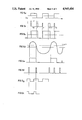
- FIGS. 5A-5H illustrate a plurality of waveforms helpful in understanding the operation of the modulator and demodulator of FIGS. 3 and 4;
- FIGS. 6a-6d are diagrams further helpful in understanding the operation of the modulator and demodulator in FIGS. 3 and 4, respectively.
- the transmitter illustrated in FIG. 1 comprises a TV camera 2 producing video analog output signals of the scene to be transmitted; an analog-to-digital converter 4 converting the analog output signals to pixel digital signals representing the gray level of each pixel in the scene; a video memory 6 storing the pixel digital values for the predetermined duration, e.g., 20 seconds; and a video modulator 8 modulating a carrier according to the pixel digital value stored in the memory for transmission via a telephone line 10 (or via a radio link) to the receiver illustrated in FIG. 2.
- the receiver in FIG. 1 comprises a TV camera 2 producing video analog output signals of the scene to be transmitted; an analog-to-digital converter 4 converting the analog output signals to pixel digital signals representing the gray level of each pixel in the scene; a video memory 6 storing the pixel digital values for the predetermined duration, e.g., 20 seconds; and a video modulator 8 modulating a carrier according to the pixel digital value stored in the memory for transmission via a telephone line 10 (or via a radio link
- a video demodulator 12 which detects the pixel digital value used for modulating the carrier signal; a memory 14 storing the pixel digital values; a digital-to-analog converter 16 for converting the pixel digital values back to analog signals; and a TV display 18 utilizing the latter analog signals to reproduce the still picture for viewing.
- the modulator unit 8 in the transmitter of FIG. 1 is more particularly illustrated in FIG. 3. Briefly, it generates a square-wave carrier, converts the modulating electrical signal from the video memory 6 (FIG. 1) to signal pulses each having a duration corresponding to the instantaneous value of the modulating electrical signals (the stored pixel gray levels), and changes the cross-over point of each square half-wave according to the duration of the signal pulses, to thereby modulate the square-wave carrier according to the pixel digital values.
- the modulator 8 comprises a local oscillator 20 which generates a high frequency square wave. This is converted by a divider 22 to a lower frequency square-wave, shown by waveform (a) in FIG. 5.
- oscillator 20 may operate at 1 MHz, and the square-wave signal output from divider 22 may be 2.5 KHz.
- the gray level (0-63) of each pixel is inputted into a down-counter 24 via its 6-bit input.
- Counter 24 determines the time of loading the gray level value of the next pixel.
- Counter 24 is controlled by a flip-flop 26 which is actuated by the output of divider 22 to produce, for each digital signal, a pulse having a duration corresponding to the digital value of the respective pixel; More particularly, flip-flop 26 is initially in a reset condition (its output is "low”).
- Divider 22 outputs pulses to flip-flop 26 until the flip-flop is set (goes "high"), at which time it turns off the "Reset” terminal of the down-counter 24.
- the latter counter starts to count down until it reaches the gray level of the pixel value inputted into the down-counter. At that time, down-counter 24 resets flip-flop 26 (which goes “low”), and the flip-flop resets down-counter 24, preparatory for the next pixel.
- output of the flip-flop is illustrated by waveform (b),
- the latter pulses waveform (b), from flip-flop 26 are received together with the square-wave carrier from divider 22, in an exclusive-or circuit 28.
- This circuit increases the zero-current point of each square half-wave according to the duration of the pulse inputted from flip-flop 26, to thereby modulate the square-wave carrier, waveform (a), FIG. 5 according to the instantaneous pixel value waveform (b).
- the so-modulated carrier signal is illustrated by waveform (c), FIG. 5.
- the modulated carrier signal is then fed through a low pass filter which removes the high-frequency harmonics, thereby producing a modulated carrier more closely resembling a sine wave.
- This signal is amplified in amplifier 32 and then applied to the telephone line via coupler 34.
- the modulated carrier signal received from telephone line 10 via coupler 36, is passed through a filter 38 tuned to the frequency of the carrier (2.5 KHz) in order to remove noise, and is then amplified in an amplifier 40.
- the amplified signal is fed to one input of a comparator 42, the other input receiving a reference signal, so as to produce at the output of the comparator a square wave signal, illustrated by waveform (e) FIG. 5, corresponding to the modulated square wave signal, waveform (c) FIG. 5, transmitted by the transmitter unit 8.
- the modulated square-wave signal is then fed to a zero-current detector 44 which detects the cross-over point of each half-square wave to produce a pulse at each such cross-over point, as illustrated by waveform (f) FIG. 5. These pulses are used to set a flip-flop 46.
- Flip-flop 46 is reset by pulses produced from a local oscillator 48 after passing through a divider 50.
- Oscillator 48 may operate at the same high frequency e.g., 1 MHz as oscillator 20 in the modulator of FIG. 3, but divider 50 reduces the frequency to 5 KHz, rather than to 2.5 KHz.
- divider 50 also supplies 1 MHz pulses to clock a counter 52 connected to the output of flip-flop 46.
- waveform (g) in FIG. 5 The 5 KHz pulses applied by divider 50 to flip-flop 46 are illustrated by waveform (g) in FIG. 5, and the output of the flip-flop is illustrated by waveform (h). It will thus be seen that waveform (h) outputted from the flip-flop is similar to the pulses illustrated by waveform (b) FIG. 5, in which the duration of each pulse corresponds to the gray level of the respective pixel.
- Counter 52 outputs the digital value representing the gray level of each such pixel.
- These digital values are applied to the TV monitor 18 (FIG. 2), thereby reproducing the original frame as transmitted by the TV camera 2 in the transmitter illustrated in FIG. 1.
- FIG. 6a illustrates the video signal as originally received by the TV camera 2 in the transmitter.
- FIGS. 6b and 6c illustrate the phase shift produced in the carrier according to the gray levels of the pixel elements. It will be seen from FIGS. 6b and 6c that the 64 gray levels of the pixel elements produce no more than a 90° shift in the phase of the carrier wave, actually from 10°-80°.
- FIG. 6d illustrates the manner in which the carrier wave (F 1 ) is shifted in phase by the pixel values to produce the modulated carrier (F 2 ).
Abstract
Description
Claims (19)
Applications Claiming Priority (2)
| Application Number | Priority Date | Filing Date | Title |
|---|---|---|---|
| IL82539A IL82539A0 (en) | 1987-05-15 | 1987-05-15 | Video communication system and phase or frequency modulator included therein |
| IL82539 | 1987-05-15 |
Publications (1)
| Publication Number | Publication Date |
|---|---|
| US4945404A true US4945404A (en) | 1990-07-31 |
Family
ID=11057802
Family Applications (1)
| Application Number | Title | Priority Date | Filing Date |
|---|---|---|---|
| US07/191,103 Expired - Fee Related US4945404A (en) | 1987-05-15 | 1988-05-06 | Video communication system and phase or frequency modulator included therein |
Country Status (9)
| Country | Link |
|---|---|
| US (1) | US4945404A (en) |
| EP (1) | EP0291036B1 (en) |
| AT (1) | ATE112916T1 (en) |
| AU (1) | AU611150B2 (en) |
| CA (1) | CA1314625C (en) |
| DE (1) | DE3851778T2 (en) |
| ES (1) | ES2065325T3 (en) |
| IL (1) | IL82539A0 (en) |
| ZA (1) | ZA883293B (en) |
Cited By (26)
| Publication number | Priority date | Publication date | Assignee | Title |
|---|---|---|---|---|
| WO1991000665A1 (en) * | 1989-06-26 | 1991-01-10 | Perelman Frank M | Video telephone employing pulse width modulation for data transmission |
| US5365576A (en) * | 1991-02-27 | 1994-11-15 | Ricos Co., Ltd. | Data and speech transmission device |
| US5677728A (en) * | 1982-02-24 | 1997-10-14 | Schoolman Scientific Corporation | Stereoscopic video telecommunication system |
| US20020071531A1 (en) * | 1989-07-14 | 2002-06-13 | Inline Connections Corporation, A Virginia Corporation | Video transmission and control system utilizing internal telephone lines |
| US20030147513A1 (en) * | 1999-06-11 | 2003-08-07 | Goodman David D. | High-speed data communication over a residential telephone wiring network |
| US20050141683A1 (en) * | 2003-12-25 | 2005-06-30 | Yoshikazu Ishii | Control and monitoring telecommunication system and method of setting a modulation method |
| US20080055142A1 (en) * | 2004-09-27 | 2008-03-06 | Stephen Deleu | Electronic Filter Device for the Reception of TV Signals |
| US7587001B2 (en) | 2006-01-11 | 2009-09-08 | Serconet Ltd. | Apparatus and method for frequency shifting of a wireless signal and systems using frequency shifting |
| US7680255B2 (en) | 2001-07-05 | 2010-03-16 | Mosaid Technologies Incorporated | Telephone outlet with packet telephony adaptor, and a network using same |
| US7686653B2 (en) | 2003-09-07 | 2010-03-30 | Mosaid Technologies Incorporated | Modular outlet |
| US7702095B2 (en) | 2003-01-30 | 2010-04-20 | Mosaid Technologies Incorporated | Method and system for providing DC power on local telephone lines |
| US7715534B2 (en) | 2000-03-20 | 2010-05-11 | Mosaid Technologies Incorporated | Telephone outlet for implementing a local area network over telephone lines and a local area network using such outlets |
| US7860084B2 (en) | 2001-10-11 | 2010-12-28 | Mosaid Technologies Incorporated | Outlet with analog signal adapter, a method for use thereof and a network using said outlet |
| US7873058B2 (en) | 2004-11-08 | 2011-01-18 | Mosaid Technologies Incorporated | Outlet with analog signal adapter, a method for use thereof and a network using said outlet |
| US8000349B2 (en) | 2000-04-18 | 2011-08-16 | Mosaid Technologies Incorporated | Telephone communication system over a single telephone line |
| US8175649B2 (en) | 2008-06-20 | 2012-05-08 | Corning Mobileaccess Ltd | Method and system for real time control of an active antenna over a distributed antenna system |
| US8238328B2 (en) | 2003-03-13 | 2012-08-07 | Mosaid Technologies Incorporated | Telephone system having multiple distinct sources and accessories therefor |
| US8270430B2 (en) | 1998-07-28 | 2012-09-18 | Mosaid Technologies Incorporated | Local area network of serial intelligent cells |
| US8325759B2 (en) | 2004-05-06 | 2012-12-04 | Corning Mobileaccess Ltd | System and method for carrying a wireless based signal over wiring |
| US8351582B2 (en) | 1999-07-20 | 2013-01-08 | Mosaid Technologies Incorporated | Network for telephony and data communication |
| US8594133B2 (en) | 2007-10-22 | 2013-11-26 | Corning Mobileaccess Ltd. | Communication system using low bandwidth wires |
| US8848725B2 (en) | 2000-04-19 | 2014-09-30 | Conversant Intellectual Property Management Incorporated | Network combining wired and non-wired segments |
| US8897215B2 (en) | 2009-02-08 | 2014-11-25 | Corning Optical Communications Wireless Ltd | Communication system using cables carrying ethernet signals |
| US9184960B1 (en) | 2014-09-25 | 2015-11-10 | Corning Optical Communications Wireless Ltd | Frequency shifting a communications signal(s) in a multi-frequency distributed antenna system (DAS) to avoid or reduce frequency interference |
| US9338823B2 (en) | 2012-03-23 | 2016-05-10 | Corning Optical Communications Wireless Ltd | Radio-frequency integrated circuit (RFIC) chip(s) for providing distributed antenna system functionalities, and related components, systems, and methods |
| US10986165B2 (en) | 2004-01-13 | 2021-04-20 | May Patents Ltd. | Information device |
Families Citing this family (6)
| Publication number | Priority date | Publication date | Assignee | Title |
|---|---|---|---|---|
| JPH02128583A (en) * | 1988-11-08 | 1990-05-16 | Mitsubishi Electric Corp | Still picture transmitting and displaying device |
| WO1991007850A1 (en) * | 1989-11-09 | 1991-05-30 | Zone Technology Pty Limited | Digital video camera |
| KR930003963B1 (en) * | 1990-08-27 | 1993-05-17 | 주식회사 금성사 | Picture image signal transmission apparatus |
| GB9101548D0 (en) * | 1991-01-24 | 1991-03-06 | Stc Plc | Surveillance system |
| FR2715528B1 (en) * | 1994-01-25 | 1996-04-05 | Mgi | Method and device for remote transmission and reception of video images. |
| DE10136677A1 (en) * | 2001-07-27 | 2003-02-13 | Harman Becker Automotive Sys | Method and arrangement for converting analog image signals into digital image signals |
Citations (6)
| Publication number | Priority date | Publication date | Assignee | Title |
|---|---|---|---|---|
| US3898589A (en) * | 1974-05-02 | 1975-08-05 | Hughes Aircraft Co | Pulse position and phase modulator |
| US4057836A (en) * | 1976-01-22 | 1977-11-08 | Robot Research, Inc. | Slow scan television scan converter |
| US4059806A (en) * | 1976-11-15 | 1977-11-22 | The Singer Company | Pulse position demodulator circuit |
| JPS53145521A (en) * | 1977-05-25 | 1978-12-18 | Oki Electric Ind Co Ltd | Receiving picture display system for television still picture communication |
| US4400717A (en) * | 1981-04-21 | 1983-08-23 | Colorado Video Incorporated | Color slow-scan TV system and method |
| US4739413A (en) * | 1985-06-14 | 1988-04-19 | Luma Telecom, Inc. | Video-optimized modulator-demodulator with adjacent modulating amplitudes matched to adjacent pixel gray values |
Family Cites Families (4)
| Publication number | Priority date | Publication date | Assignee | Title |
|---|---|---|---|---|
| GB1393674A (en) * | 1971-06-01 | 1975-05-07 | Rca Corp | Telephone image transmission system |
| DE2808640C2 (en) * | 1978-02-28 | 1983-06-16 | Siemens AG, 1000 Berlin und 8000 München | System for the transmission of individual television images |
| JPS57125590A (en) * | 1981-01-28 | 1982-08-04 | Nec Corp | Still picture transmitter |
| FR2514974B1 (en) * | 1981-10-15 | 1986-11-28 | Telediffusion Fse | PACKET DATA BROADCASTING SYSTEM |
-
1987
- 1987-05-15 IL IL82539A patent/IL82539A0/en not_active IP Right Cessation
-
1988
- 1988-05-06 US US07/191,103 patent/US4945404A/en not_active Expired - Fee Related
- 1988-05-06 CA CA000566221A patent/CA1314625C/en not_active Expired - Fee Related
- 1988-05-10 ZA ZA883293A patent/ZA883293B/en unknown
- 1988-05-11 ES ES88107583T patent/ES2065325T3/en not_active Expired - Lifetime
- 1988-05-11 EP EP88107583A patent/EP0291036B1/en not_active Expired - Lifetime
- 1988-05-11 DE DE3851778T patent/DE3851778T2/en not_active Expired - Fee Related
- 1988-05-11 AT AT88107583T patent/ATE112916T1/en not_active IP Right Cessation
- 1988-05-12 AU AU16106/88A patent/AU611150B2/en not_active Ceased
Patent Citations (6)
| Publication number | Priority date | Publication date | Assignee | Title |
|---|---|---|---|---|
| US3898589A (en) * | 1974-05-02 | 1975-08-05 | Hughes Aircraft Co | Pulse position and phase modulator |
| US4057836A (en) * | 1976-01-22 | 1977-11-08 | Robot Research, Inc. | Slow scan television scan converter |
| US4059806A (en) * | 1976-11-15 | 1977-11-22 | The Singer Company | Pulse position demodulator circuit |
| JPS53145521A (en) * | 1977-05-25 | 1978-12-18 | Oki Electric Ind Co Ltd | Receiving picture display system for television still picture communication |
| US4400717A (en) * | 1981-04-21 | 1983-08-23 | Colorado Video Incorporated | Color slow-scan TV system and method |
| US4739413A (en) * | 1985-06-14 | 1988-04-19 | Luma Telecom, Inc. | Video-optimized modulator-demodulator with adjacent modulating amplitudes matched to adjacent pixel gray values |
Cited By (67)
| Publication number | Priority date | Publication date | Assignee | Title |
|---|---|---|---|---|
| US5677728A (en) * | 1982-02-24 | 1997-10-14 | Schoolman Scientific Corporation | Stereoscopic video telecommunication system |
| WO1991000665A1 (en) * | 1989-06-26 | 1991-01-10 | Perelman Frank M | Video telephone employing pulse width modulation for data transmission |
| US20050117721A1 (en) * | 1989-07-14 | 2005-06-02 | Goodman David D. | Video transmission and control system utilizing internal telephone lines |
| US20020071531A1 (en) * | 1989-07-14 | 2002-06-13 | Inline Connections Corporation, A Virginia Corporation | Video transmission and control system utilizing internal telephone lines |
| US20050117722A1 (en) * | 1989-07-14 | 2005-06-02 | Inline Connection Corporation | Video transmission and control system utilizing internal telephone lines |
| US5365576A (en) * | 1991-02-27 | 1994-11-15 | Ricos Co., Ltd. | Data and speech transmission device |
| US8885659B2 (en) | 1998-07-28 | 2014-11-11 | Conversant Intellectual Property Management Incorporated | Local area network of serial intelligent cells |
| US8908673B2 (en) | 1998-07-28 | 2014-12-09 | Conversant Intellectual Property Management Incorporated | Local area network of serial intelligent cells |
| US8885660B2 (en) | 1998-07-28 | 2014-11-11 | Conversant Intellectual Property Management Incorporated | Local area network of serial intelligent cells |
| US8270430B2 (en) | 1998-07-28 | 2012-09-18 | Mosaid Technologies Incorporated | Local area network of serial intelligent cells |
| US8867523B2 (en) | 1998-07-28 | 2014-10-21 | Conversant Intellectual Property Management Incorporated | Local area network of serial intelligent cells |
| US8325636B2 (en) | 1998-07-28 | 2012-12-04 | Mosaid Technologies Incorporated | Local area network of serial intelligent cells |
| US20030147513A1 (en) * | 1999-06-11 | 2003-08-07 | Goodman David D. | High-speed data communication over a residential telephone wiring network |
| US8929523B2 (en) | 1999-07-20 | 2015-01-06 | Conversant Intellectual Property Management Inc. | Network for telephony and data communication |
| US8351582B2 (en) | 1999-07-20 | 2013-01-08 | Mosaid Technologies Incorporated | Network for telephony and data communication |
| US8363797B2 (en) | 2000-03-20 | 2013-01-29 | Mosaid Technologies Incorporated | Telephone outlet for implementing a local area network over telephone lines and a local area network using such outlets |
| US7715534B2 (en) | 2000-03-20 | 2010-05-11 | Mosaid Technologies Incorporated | Telephone outlet for implementing a local area network over telephone lines and a local area network using such outlets |
| US8855277B2 (en) | 2000-03-20 | 2014-10-07 | Conversant Intellectual Property Managment Incorporated | Telephone outlet for implementing a local area network over telephone lines and a local area network using such outlets |
| US8559422B2 (en) | 2000-04-18 | 2013-10-15 | Mosaid Technologies Incorporated | Telephone communication system over a single telephone line |
| US8000349B2 (en) | 2000-04-18 | 2011-08-16 | Mosaid Technologies Incorporated | Telephone communication system over a single telephone line |
| US8223800B2 (en) | 2000-04-18 | 2012-07-17 | Mosaid Technologies Incorporated | Telephone communication system over a single telephone line |
| US8873575B2 (en) | 2000-04-19 | 2014-10-28 | Conversant Intellectual Property Management Incorporated | Network combining wired and non-wired segments |
| US8982904B2 (en) | 2000-04-19 | 2015-03-17 | Conversant Intellectual Property Management Inc. | Network combining wired and non-wired segments |
| US8873586B2 (en) | 2000-04-19 | 2014-10-28 | Conversant Intellectual Property Management Incorporated | Network combining wired and non-wired segments |
| US8867506B2 (en) | 2000-04-19 | 2014-10-21 | Conversant Intellectual Property Management Incorporated | Network combining wired and non-wired segments |
| US8848725B2 (en) | 2000-04-19 | 2014-09-30 | Conversant Intellectual Property Management Incorporated | Network combining wired and non-wired segments |
| US8472593B2 (en) | 2001-07-05 | 2013-06-25 | Mosaid Technologies Incorporated | Telephone outlet with packet telephony adaptor, and a network using same |
| US7680255B2 (en) | 2001-07-05 | 2010-03-16 | Mosaid Technologies Incorporated | Telephone outlet with packet telephony adaptor, and a network using same |
| US7769030B2 (en) | 2001-07-05 | 2010-08-03 | Mosaid Technologies Incorporated | Telephone outlet with packet telephony adapter, and a network using same |
| US8761186B2 (en) | 2001-07-05 | 2014-06-24 | Conversant Intellectual Property Management Incorporated | Telephone outlet with packet telephony adapter, and a network using same |
| US7860084B2 (en) | 2001-10-11 | 2010-12-28 | Mosaid Technologies Incorporated | Outlet with analog signal adapter, a method for use thereof and a network using said outlet |
| US7889720B2 (en) | 2001-10-11 | 2011-02-15 | Mosaid Technologies Incorporated | Outlet with analog signal adapter, a method for use thereof and a network using said outlet |
| US7953071B2 (en) | 2001-10-11 | 2011-05-31 | Mosaid Technologies Incorporated | Outlet with analog signal adapter, a method for use thereof and a network using said outlet |
| US8787562B2 (en) | 2003-01-30 | 2014-07-22 | Conversant Intellectual Property Management Inc. | Method and system for providing DC power on local telephone lines |
| US7702095B2 (en) | 2003-01-30 | 2010-04-20 | Mosaid Technologies Incorporated | Method and system for providing DC power on local telephone lines |
| US8107618B2 (en) | 2003-01-30 | 2012-01-31 | Mosaid Technologies Incorporated | Method and system for providing DC power on local telephone lines |
| US8238328B2 (en) | 2003-03-13 | 2012-08-07 | Mosaid Technologies Incorporated | Telephone system having multiple distinct sources and accessories therefor |
| US7867035B2 (en) | 2003-07-09 | 2011-01-11 | Mosaid Technologies Incorporated | Modular outlet |
| US7686653B2 (en) | 2003-09-07 | 2010-03-30 | Mosaid Technologies Incorporated | Modular outlet |
| US8591264B2 (en) | 2003-09-07 | 2013-11-26 | Mosaid Technologies Incorporated | Modular outlet |
| US8092258B2 (en) | 2003-09-07 | 2012-01-10 | Mosaid Technologies Incorporated | Modular outlet |
| US8360810B2 (en) | 2003-09-07 | 2013-01-29 | Mosaid Technologies Incorporated | Modular outlet |
| US8235755B2 (en) | 2003-09-07 | 2012-08-07 | Mosaid Technologies Incorporated | Modular outlet |
| US7570748B2 (en) * | 2003-12-25 | 2009-08-04 | Hitachi, Ltd. | Control and monitoring telecommunication system and method of setting a modulation method |
| US20050141683A1 (en) * | 2003-12-25 | 2005-06-30 | Yoshikazu Ishii | Control and monitoring telecommunication system and method of setting a modulation method |
| US10986165B2 (en) | 2004-01-13 | 2021-04-20 | May Patents Ltd. | Information device |
| US10986164B2 (en) | 2004-01-13 | 2021-04-20 | May Patents Ltd. | Information device |
| US11032353B2 (en) | 2004-01-13 | 2021-06-08 | May Patents Ltd. | Information device |
| US11095708B2 (en) | 2004-01-13 | 2021-08-17 | May Patents Ltd. | Information device |
| US8325759B2 (en) | 2004-05-06 | 2012-12-04 | Corning Mobileaccess Ltd | System and method for carrying a wireless based signal over wiring |
| US7541957B2 (en) * | 2004-09-27 | 2009-06-02 | Unitron | Electronic filter device for the reception of TV signals |
| US20080055142A1 (en) * | 2004-09-27 | 2008-03-06 | Stephen Deleu | Electronic Filter Device for the Reception of TV Signals |
| US7873058B2 (en) | 2004-11-08 | 2011-01-18 | Mosaid Technologies Incorporated | Outlet with analog signal adapter, a method for use thereof and a network using said outlet |
| US8184681B2 (en) | 2006-01-11 | 2012-05-22 | Corning Mobileaccess Ltd | Apparatus and method for frequency shifting of a wireless signal and systems using frequency shifting |
| US7813451B2 (en) | 2006-01-11 | 2010-10-12 | Mobileaccess Networks Ltd. | Apparatus and method for frequency shifting of a wireless signal and systems using frequency shifting |
| US7587001B2 (en) | 2006-01-11 | 2009-09-08 | Serconet Ltd. | Apparatus and method for frequency shifting of a wireless signal and systems using frequency shifting |
| US8594133B2 (en) | 2007-10-22 | 2013-11-26 | Corning Mobileaccess Ltd. | Communication system using low bandwidth wires |
| US9813229B2 (en) | 2007-10-22 | 2017-11-07 | Corning Optical Communications Wireless Ltd | Communication system using low bandwidth wires |
| US9549301B2 (en) | 2007-12-17 | 2017-01-17 | Corning Optical Communications Wireless Ltd | Method and system for real time control of an active antenna over a distributed antenna system |
| US8175649B2 (en) | 2008-06-20 | 2012-05-08 | Corning Mobileaccess Ltd | Method and system for real time control of an active antenna over a distributed antenna system |
| US8897215B2 (en) | 2009-02-08 | 2014-11-25 | Corning Optical Communications Wireless Ltd | Communication system using cables carrying ethernet signals |
| US9948329B2 (en) | 2012-03-23 | 2018-04-17 | Corning Optical Communications Wireless, LTD | Radio-frequency integrated circuit (RFIC) chip(s) for providing distributed antenna system functionalities, and related components, systems, and methods |
| US10141959B2 (en) | 2012-03-23 | 2018-11-27 | Corning Optical Communications Wireless Ltd | Radio-frequency integrated circuit (RFIC) chip(s) for providing distributed antenna system functionalities, and related components, systems, and methods |
| US9338823B2 (en) | 2012-03-23 | 2016-05-10 | Corning Optical Communications Wireless Ltd | Radio-frequency integrated circuit (RFIC) chip(s) for providing distributed antenna system functionalities, and related components, systems, and methods |
| US9515855B2 (en) | 2014-09-25 | 2016-12-06 | Corning Optical Communications Wireless Ltd | Frequency shifting a communications signal(s) in a multi-frequency distributed antenna system (DAS) to avoid or reduce frequency interference |
| US9253003B1 (en) | 2014-09-25 | 2016-02-02 | Corning Optical Communications Wireless Ltd | Frequency shifting a communications signal(S) in a multi-frequency distributed antenna system (DAS) to avoid or reduce frequency interference |
| US9184960B1 (en) | 2014-09-25 | 2015-11-10 | Corning Optical Communications Wireless Ltd | Frequency shifting a communications signal(s) in a multi-frequency distributed antenna system (DAS) to avoid or reduce frequency interference |
Also Published As
| Publication number | Publication date |
|---|---|
| EP0291036B1 (en) | 1994-10-12 |
| ZA883293B (en) | 1988-11-14 |
| ATE112916T1 (en) | 1994-10-15 |
| EP0291036A2 (en) | 1988-11-17 |
| AU1610688A (en) | 1988-11-17 |
| DE3851778D1 (en) | 1994-11-17 |
| CA1314625C (en) | 1993-03-16 |
| EP0291036A3 (en) | 1991-08-28 |
| DE3851778T2 (en) | 1995-02-23 |
| AU611150B2 (en) | 1991-06-06 |
| IL82539A0 (en) | 1987-11-30 |
| ES2065325T3 (en) | 1995-02-16 |
Similar Documents
| Publication | Publication Date | Title |
|---|---|---|
| US4945404A (en) | Video communication system and phase or frequency modulator included therein | |
| US3838444A (en) | System for transmitting auxiliary information in low energy density portion of color tv spectrum | |
| US3761610A (en) | High speed fascimile systems | |
| US3562420A (en) | Pseudo random quantizing systems for transmitting television signals | |
| RU98101821A (en) | DEVICE OF MULTIMEDIA INPUT AND MANAGEMENT AND METHOD OF MULTIMEDIA COMMUNICATIONS | |
| EP0710022A2 (en) | System and method for encoding digital information in a television signal | |
| US6665019B1 (en) | Method and apparatus for spread spectrum clocking of digital video | |
| US4928318A (en) | Optical signal transmission system including pulsed FM modulator/demodulator | |
| US6141032A (en) | Method and apparatus for encoding, transmitting, storing and decoding of data | |
| GB1280049A (en) | Television camera system | |
| US4034405A (en) | Television facsimile transmission system | |
| US2435736A (en) | Frequency modulated picture receiver | |
| JPH0352390A (en) | Phase synchronous loop type 90 degree phase shift modulating and demodulating method and circuit | |
| US2694104A (en) | Subscriber television system | |
| EP0394486A1 (en) | Television receiver | |
| US5909256A (en) | Telecommunication system for transmitting and receiving non-compressed high resolution analog signals | |
| KR900701120A (en) | High definition television signal transmission and reception method and system | |
| US5953043A (en) | Signal transmission system | |
| US2656405A (en) | Air key subscriber television system | |
| US4489411A (en) | Process and a circuit arrangement for signal transmission using an amplitude-modulated radio broadcasting system | |
| US3526705A (en) | Subcarrier circuits for colour television apparatus | |
| US2694105A (en) | Subscriber television transmitter | |
| US2755332A (en) | Subscription television system | |
| US3507986A (en) | Sync slipper | |
| JP2548819B2 (en) | Image transmitter / receiver |
Legal Events
| Date | Code | Title | Description |
|---|---|---|---|
| AS | Assignment |
Owner name: MEDAON LTD., 27 JABOTINSKY STREET, JERUSALEM, ISRA Free format text: ASSIGNMENT OF ASSIGNORS INTEREST.;ASSIGNOR:MILLER, GERSHON;REEL/FRAME:004882/0235 Effective date: 19880427 Owner name: MEDAON LTD., A ISRAELI CORP.,ISRAEL Free format text: ASSIGNMENT OF ASSIGNORS INTEREST;ASSIGNOR:MILLER, GERSHON;REEL/FRAME:004882/0235 Effective date: 19880427 |
|
| FEPP | Fee payment procedure |
Free format text: PAYOR NUMBER ASSIGNED (ORIGINAL EVENT CODE: ASPN); ENTITY STATUS OF PATENT OWNER: SMALL ENTITY |
|
| FPAY | Fee payment |
Year of fee payment: 4 |
|
| REMI | Maintenance fee reminder mailed | ||
| LAPS | Lapse for failure to pay maintenance fees | ||
| FP | Lapsed due to failure to pay maintenance fee |
Effective date: 19980731 |
|
| STCH | Information on status: patent discontinuation |
Free format text: PATENT EXPIRED DUE TO NONPAYMENT OF MAINTENANCE FEES UNDER 37 CFR 1.362 |