US4911517A - Means for clamping fiber optical cable - Google Patents
Means for clamping fiber optical cable Download PDFInfo
- Publication number
- US4911517A US4911517A US07/242,359 US24235988A US4911517A US 4911517 A US4911517 A US 4911517A US 24235988 A US24235988 A US 24235988A US 4911517 A US4911517 A US 4911517A
- Authority
- US
- United States
- Prior art keywords
- fiber
- clamp
- light
- cable
- switch
- Prior art date
- Legal status (The legal status is an assumption and is not a legal conclusion. Google has not performed a legal analysis and makes no representation as to the accuracy of the status listed.)
- Expired - Fee Related
Links
Images


Classifications
-
- G—PHYSICS
- G02—OPTICS
- G02B—OPTICAL ELEMENTS, SYSTEMS OR APPARATUS
- G02B6/00—Light guides; Structural details of arrangements comprising light guides and other optical elements, e.g. couplings
- G02B6/24—Coupling light guides
- G02B6/26—Optical coupling means
- G02B6/35—Optical coupling means having switching means
- G02B6/351—Optical coupling means having switching means involving stationary waveguides with moving interposed optical elements
- G02B6/3512—Optical coupling means having switching means involving stationary waveguides with moving interposed optical elements the optical element being reflective, e.g. mirror
- G02B6/3514—Optical coupling means having switching means involving stationary waveguides with moving interposed optical elements the optical element being reflective, e.g. mirror the reflective optical element moving along a line so as to translate into and out of the beam path, i.e. across the beam path
-
- G—PHYSICS
- G02—OPTICS
- G02B—OPTICAL ELEMENTS, SYSTEMS OR APPARATUS
- G02B6/00—Light guides; Structural details of arrangements comprising light guides and other optical elements, e.g. couplings
- G02B6/24—Coupling light guides
- G02B6/36—Mechanical coupling means
- G02B6/3616—Holders, macro size fixtures for mechanically holding or positioning fibres, e.g. on an optical bench
-
- G—PHYSICS
- G02—OPTICS
- G02B—OPTICAL ELEMENTS, SYSTEMS OR APPARATUS
- G02B6/00—Light guides; Structural details of arrangements comprising light guides and other optical elements, e.g. couplings
- G02B6/44—Mechanical structures for providing tensile strength and external protection for fibres, e.g. optical transmission cables
- G02B6/4439—Auxiliary devices
- G02B6/4471—Terminating devices ; Cable clamps
-
- G—PHYSICS
- G02—OPTICS
- G02B—OPTICAL ELEMENTS, SYSTEMS OR APPARATUS
- G02B6/00—Light guides; Structural details of arrangements comprising light guides and other optical elements, e.g. couplings
- G02B6/24—Coupling light guides
- G02B6/25—Preparing the ends of light guides for coupling, e.g. cutting
-
- G—PHYSICS
- G02—OPTICS
- G02B—OPTICAL ELEMENTS, SYSTEMS OR APPARATUS
- G02B6/00—Light guides; Structural details of arrangements comprising light guides and other optical elements, e.g. couplings
- G02B6/24—Coupling light guides
- G02B6/26—Optical coupling means
- G02B6/35—Optical coupling means having switching means
- G02B6/354—Switching arrangements, i.e. number of input/output ports and interconnection types
- G02B6/3544—2D constellations, i.e. with switching elements and switched beams located in a plane
- G02B6/3548—1xN switch, i.e. one input and a selectable single output of N possible outputs
- G02B6/3552—1x1 switch, e.g. on/off switch
-
- G—PHYSICS
- G02—OPTICS
- G02B—OPTICAL ELEMENTS, SYSTEMS OR APPARATUS
- G02B6/00—Light guides; Structural details of arrangements comprising light guides and other optical elements, e.g. couplings
- G02B6/24—Coupling light guides
- G02B6/26—Optical coupling means
- G02B6/35—Optical coupling means having switching means
- G02B6/3564—Mechanical details of the actuation mechanism associated with the moving element or mounting mechanism details
- G02B6/3568—Mechanical details of the actuation mechanism associated with the moving element or mounting mechanism details characterised by the actuating force
- G02B6/3574—Mechanical force, e.g. pressure variations
-
- G—PHYSICS
- G02—OPTICS
- G02B—OPTICAL ELEMENTS, SYSTEMS OR APPARATUS
- G02B6/00—Light guides; Structural details of arrangements comprising light guides and other optical elements, e.g. couplings
- G02B6/24—Coupling light guides
- G02B6/26—Optical coupling means
- G02B6/35—Optical coupling means having switching means
- G02B6/3564—Mechanical details of the actuation mechanism associated with the moving element or mounting mechanism details
- G02B6/358—Latching of the moving element, i.e. maintaining or holding the moving element in place once operation has been performed; includes a mechanically bistable system
-
- G—PHYSICS
- G02—OPTICS
- G02B—OPTICAL ELEMENTS, SYSTEMS OR APPARATUS
- G02B6/00—Light guides; Structural details of arrangements comprising light guides and other optical elements, e.g. couplings
- G02B6/24—Coupling light guides
- G02B6/36—Mechanical coupling means
- G02B6/3628—Mechanical coupling means for mounting fibres to supporting carriers
- G02B6/3632—Mechanical coupling means for mounting fibres to supporting carriers characterised by the cross-sectional shape of the mechanical coupling means
- G02B6/3636—Mechanical coupling means for mounting fibres to supporting carriers characterised by the cross-sectional shape of the mechanical coupling means the mechanical coupling means being grooves
-
- G—PHYSICS
- G02—OPTICS
- G02B—OPTICAL ELEMENTS, SYSTEMS OR APPARATUS
- G02B6/00—Light guides; Structural details of arrangements comprising light guides and other optical elements, e.g. couplings
- G02B6/24—Coupling light guides
- G02B6/36—Mechanical coupling means
- G02B6/38—Mechanical coupling means having fibre to fibre mating means
- G02B6/3807—Dismountable connectors, i.e. comprising plugs
- G02B6/381—Dismountable connectors, i.e. comprising plugs of the ferrule type, e.g. fibre ends embedded in ferrules, connecting a pair of fibres
- G02B6/3818—Dismountable connectors, i.e. comprising plugs of the ferrule type, e.g. fibre ends embedded in ferrules, connecting a pair of fibres of a low-reflection-loss type
- G02B6/3821—Dismountable connectors, i.e. comprising plugs of the ferrule type, e.g. fibre ends embedded in ferrules, connecting a pair of fibres of a low-reflection-loss type with axial spring biasing or loading means
Definitions
- This invention relates to control switches for electrical devices.
- it relates to devices for controlling electrical equipment from an area that contains or may contain explosive fumes or vapors, dust, or the like.
- a hazard arises because the opening of electrical contacts carrying current in a circuit that has any inductance will produce an arc that may ignite the explosive vapors.
- An explosion-proof enclosure This is an enclosure that is made to be sealed so as to be water-tight and pressure-tight. Enclosures for electrical devices to be used in such an atmosphere are typically cast instead of stamped. They are normally assembled with gaskets and bolts to maintain a seal. The result is an enclosure that is considerably more expensive to purchase than those made for areas that are not hazardous. The hazardous-duty enclosures require maintenance not required by enclosures designed for non-hazardous areas.
- optical fibers as a means for linking mechanical controls in the hazardous area to electrical controls outside the hazardous area.
- a source of light outside the hazardous area is coupled to an optical fiber that is taken to an input device in the hazardous area.
- the input device which may be a pushbutton, foot switch, limit switch, pressure switch or the like, includes an interruptible path for light which may be reflected to a second fiber in the input device that is connected back to a receiver outside the hazardous area. Operation of the switch in the hazardous area either permits the passage of light or interrupts it.
- Systems such as the one described have been used in petrochemical processing plants, refineries, plants manufacturing explosives, grain-handling facilities and the like.
- the inherently safe systems now in use present several disadvantages.
- the first of these is the frequent use of two optical fibers for each switch.
- One optical fiber is used to conduct light from the light source to the input device, and a second is used to conduct reflected light back to a receiver outside the hazardous area.
- the light source and receiver are often located together so that a double optical cable may be used.
- the use of two such cables often requires four cable terminations that must be made to connect an inherently safe switch.
- a light-operated switch should respond only to a signal from a desired source, and should not be triggered by changes in the ambient light level.
- an optical switch for inherently-safe use is made to be installed by electricians without special tools or training. If an optical switch requires field installation of terminations for which the ends of an optical cable must be ground and set with epoxy or the like, the switch is made much more difficult to use.
- a fiber-optic switch uses a single optical fiber for two-way communication with light.
- a switching mechanism has no electrical part and is thus appropriate for placement in an area having explosive or combustible materials.
- the optical fiber can be cut to length in the field and can be installed without sepcial tools or training.
- the fiber is held in place by a clip that is constrained to compress the fiber and grip it securely.
- a snap-action mirror reflects light back into the fiber in one position and does not reflect it in another position.
- An electronic circuit provides pulsed light and determines coincidence of sent and received pulses to discriminate against operation of the switch by ambient light or other spurious signals.
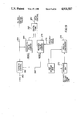
- FIG. 1 is an overall block diagram of an apparatus for the practice of the present invention.
- FIG. 2 is a front view of a module and an operator for the practice of the present invention.
- FIG. 3 is a side view of the module and operator of FIG. 2.
- FIG. 4 is a view of the module and operator along viewing lines 4--4 of FIG. 2.
- FIG. 5 is a view of the module and operator along viewing lines 5--5 of FIG. 3.
- FIG. 6 is a split plan view of an operator for the nature of the present invention.
- FIG. 7 is a side view of the stem and mirror of FIG. 6 in the on position.
- FIG. 8 is a side view of the stem and mirror of FIG. 6 in the unstable snap position.
- FIG. 9 is an exploded view of the components of the module of the present invention.
- FIG. 10 is a front view of the arm 150 of FIG. 6.
- FIG. 11 is a side view of the arm 150 of FIG. 6.
- FIG. 12 is a bottom view of the arm 150 of FIG. 6.
- FIG. 13 is a side view of the clamp in the unclamped position.
- FIG. 14 is a side view of the clamp in the clamped position.
- FIG. 15 is a top view of the clamp.
- FIG. 16 is a functional block diagram of a transceiver for the practice of the present invention.
- FIG. 17 is a partial sectional view of the transceiver 112 of FIG. 1.
- FIG. 18 is a circuit diagram of an electronic circuit in the transceiver 112.
- FIG. 19 is a functional block diagram of the circuit of the ASIC 248 of FIG. 18.
- FIG. 20 represents a circuit element of a realization of the ASIC 249 of FIG. 18.
- FIG. 21 represents a circuit element of a realization of the ASIC 249 of FIG. 18.
- FIG. 22 represents a circuit element of a realization of the ASIC 249 of FIG. 18.
- FIG. 1 is an overall block diagram of an apparatus for the practice of the present invention.
- an optical fiber 100 is passed through a wall 102 that separates an explosive region 104 from a safe region 106.
- the explosive region 104 may contain explosive vapors, dust or the like.
- An operator 108 is located in the explosive region 104 to operate a switch module 110.
- the operator may be a push button, rotary switch, limit switch, proximity switch or the like.
- the operator 108 and the switch module 110 contain no electrical components.
- the switch module 110 is connected by the optical fiber 100 to a transceiver 112 that is located in the safe region 106.
- the transceiver 112 generates light signals that are coupled by the optical fiber 100 to the switch module 110 and back.
- the transceiver 112 connects power lines 114 either to a relay 116 and then to switched power lines 118, or directly from the transceiver 112 to the switched power lines 118.
- the switched power lines 118 are here shown connected to a motor 120, which is taken as a typical load to be controlled by the present invention. Any other electrical load would do equally as well for the practice of the present invention.
- FIG. 2 is a front view of a module and an operator for the practice of the present invention
- FIG. 3 is a side view of the module and operator of FIG. 2
- FIG. 4 is an end view of the module and operator along viewing lines 4--4 of FIG. 2
- FIG. 5 is a top view of the module and operator of FIG. 3 along viewing lines 5--5 of FIG. 3.
- the operator 108 is a dual-position push button operator.
- a pushbutton 130 is in a neutral position which will be seen to interrupt the flow of light in the optical fiber 100 and also in an optical fiber 132. It will be seen that with the push button 130 in a neutral position, light is interrupted and the optical fibers 100 and 132.
- the operator 108 includes a collar 134 that is attached to an opening in a panel box (not shown) by a nut 136 that compresses gaskets 138.
- the optical fiber 100 is held in place by a clamp 140 and the optical 132 is held in place by a clamp 142. Details of the clamps 140 and 142 will be shown below.
- Two screws 144 and 146 secure the switch module 110 to the operator 108.
- FIG. 6 is a split plan view of an operator for the practice of the present invention.
- two separate fiber optic cables 100 and 132 are shown. Either by itself is adapted for the practice of the invention, but the two are shown because it is often desirable to have a switch that provides either a normally closed switch, which is referred to in terms of a fiber optic switch as normally light (NL), or a normally open switch, normally dark (ND).
- NL normally light
- ND normally dark
- the arm 150 is ND and the arm 152 is NL.
- the arm 150 includes an axle 154 that allows a limited amount of rotation of the arm 152. That rotation is limited by a first stop 156 that stops the arm 150 in a position that is normally dark.
- a second stop 158 stops the arm 150 in a position that is normally light.
- the change between these two positions represented a rotation about the axle 154 of about six degrees.
- the arm 150 could equally as well have been caused to translate or execute any other motion that would either place a mirror 160 so as to reflect light as shown with the arm 152, or that would place a mirror 162 away from the fiber 100 so as to prevent reflection.
- snap action is initiated by a slider 164 that operates against a coil spring 166.
- the snap action is caused by a torsion spring 168 that exerts a force to push a contact point 170 away from the slider 164.
- Movement of the slider 164 to an overcenter position snaps the arm 150 into a position opposite to the one it has been in.
- FIG. 7 shows the arm 150 in one of the two stable positions
- FIG. 9 shows the arm 150 in the unstable position in which it is about to snap or toggle.
- FIG. 9 is an exploded view of the module of the present invention.
- an upper portion 172 of the switch module 110 has a curved groove 174 that serves to guide an inserted optical fiber to a stop that is not shown.
- the slider 164 is assembled within the upper portion 172 and is biased in a preferred direction by the spring 166.
- the spring 168 is shown here in its unstressed condition. When connected, it couples the slider 164 to the arm 150 as described above.
- a bottom portion 174 of the housing 110 captures the fiber clamp 140.
- FIGS. 10, 11 and 12 are respecively front, side and bottom views of the arm 150 of FIG. 6.
- a mirror 180 is preferably made of small reflecting spheres to return incident light in its direction of entry, although good results could also be attained with a silvered or other reflecting surface.
- the axle 154 could equally as well comprise a hub for engagement with a fixed projection, and the mirror 180 could be given its relative motion by translation rather than rotation.
- FIGS. 13, 14 and 15 are respectively two side views and a top view of the clamp 140 of FIG. 2.
- the optical fiber 100 is shown first in its uncaptured position, free of the clamp 140.
- motion of the clamp 140 in the direction of the arrow 190 captures the optical fiber 100 as shown in FIGS. 14 and 15 by compressing the optical fiber 100.
- Two arrows 192 and 194 indicate the directions of forces exerted on the clamp 140 by the switch module 110.
- a handle 196 protrudes from the module 110 to enable an operator to clamp the optical fiber 100.
- FIG. 16 is a functional block diagram of a transceiver for the practice of the present invention.
- a source 210 produces light that is taken to a splitter 212.
- the source 210 was a light-emitting diode that was pulsed with square waves at a frequency of 16 kHz. If the source is pulsed, the frequency and duty cycle are matters of design choice.
- the light enters the splitter 212 where it is coupled into the optical fiber 214 to be taken to the mirror 216 for reflection and return to the splitter 212.
- the operator 218 places the mirror 216 into or out of a reflecting position as described above.
- Outputs from the source 210 and the splitter 212 are taken to a comparator 220 to provide an indication that the operator 218 has been operated.
- the source 210 was pulsed to increase the discrimination between the on condition and the off condition.
- the comparator 220 was part of a circuit to be described more fully later that compared source pulses with received pulses and produced an output to a relay 222 only upon receipt of a predetermined number of coincident pulses. This discrimination could also be handled with a dc light source by level comparison in the comparator 220. In a typical application an optical fiber without a mirror, in the dark condition, returns about four percent of the light from the source 210. This presents a possible means of distinguishing between the on and off conditions. However, the pulse method is preferred.
- FIG. 17 is a partial sectional view of the transceiver 112 of FIG. 1 showing how contact is made with an optical fiber.
- the optical fiber 100 is butted against a terminator 230 that is held against the end of the optical fiber 100 by a spring 232.
- the terminator 230 is preferably a factory-produced termination attached to a fiber optical cable 234 that is connected by epoxy or similar means to make a termination.
- the spring-loaded support of the terminator 230 makes a low-loss contact between the fiber 100 and the cable 234 that minimizes unwanted reflections.
- FIG. 18 is a circuit diagram of an electronic circuit in the transceiver 112 that produces and detect light for the practice of the present invention.
- a power supply 240 produces operating voltages for the transceiver 112 from a wide range of input ac or dc voltages.
- the power supply 240 includes a voltage regulating circuit 242 that produces a regulated voltage to operate parts of the circuit.
- An emitter 244, typically an LED, produces light that is taken to the optical fiber 100 through a splitter, and a detector 246, typically a photodiode, detects light returned in the optical fiber 100.
- the emitter 244 and the detector 246 are operated under the conrol of an application-specific integrated circuit (ASIC) 248, which also controls a transistor 250 that drives a relay 252.
- ASIC application-specific integrated circuit
- FIG. 19 is a functional block diagram of the circuit of the ASIC 248 of FIG. 18.
- a terminal 260 indicates a source of frequency that is typically a resistor-capacitor combination attached to the ASIC 248.
- the terminal 260 is connected to a timing and control block 262 which produces on a line 264 a pulse to control pulses from the emitter 244.
- the line 264 is also connected to a transmitted-pulse counter 266, which is reset by a signal from the timing and control block 262 on a line 268.
- Received pulses from the detector 246 are taken to a bandpass amplifier 270, which is also coupled to a reference voltage generator 272. This is part of a system for protecting the system from operating in response to ambient light or other spurious signals.
- the reference voltage generator 272 and the bandpass amplifier 270 are coupled to an analog comparator 274, which produces a received-pulse signal on a line 276.
- the line 276 is connected to a received pulse counter 278, which is reset by the signal on the line 268.
- Outputs of the counters 266 and 278 are taken to a comparator 280, which produces an output on a line 282 that is taken to the transistor 250 of FIG. 18 to control the relay 252.
- FIGS. 20, 21 and 22 represent circuit elements of a realization of the ASIC 248 of FIG. 18, identified as to the corresponding elements of FIG. 19.
- FIG. 20 is a realization of the bandpass amplifier 270, the reference voltage generator 272 and the analog comparator 274 of FIG. 18.
- FIG. 21 is a realization of the timing and control block 262 and the transmitted pulse counter 266 of FIG. 18, and
- FIG. 22 is a realization of the received-pulse counter 278 and the digital comparator 280 of FIG. 18.
Abstract
Description
Claims (3)
Priority Applications (10)
| Application Number | Priority Date | Filing Date | Title |
|---|---|---|---|
| US07/242,359 US4911517A (en) | 1988-09-09 | 1988-09-09 | Means for clamping fiber optical cable |
| DE89911127T DE68909798T2 (en) | 1988-09-09 | 1989-09-11 | MEANS FOR CLAMPING AN OPTICAL FIBER CABLE. |
| PCT/US1989/003946 WO1990002965A1 (en) | 1988-09-09 | 1989-09-11 | Means for clamping fiber optical cable |
| EP89911127A EP0433392B1 (en) | 1988-09-09 | 1989-09-11 | Means for clamping fiber optical cable |
| MX017507A MX169219B (en) | 1988-09-09 | 1989-09-11 | MEANS TO SECURE FIBER OPTIC CABLE |
| CA000610979A CA1323224C (en) | 1988-09-09 | 1989-09-11 | Means for clamping fiber optical cable |
| AU43366/89A AU639893B2 (en) | 1988-09-09 | 1989-09-11 | Means for clamping fiber optical cable |
| US07/433,940 US5048920A (en) | 1988-09-09 | 1989-11-09 | Fiber to fiber connection |
| US07/635,841 US5185839A (en) | 1988-09-09 | 1990-12-31 | Fiber optic cable receptacle |
| US07/707,888 US5170446A (en) | 1988-09-09 | 1991-05-31 | Rotational optical switch |
Applications Claiming Priority (1)
| Application Number | Priority Date | Filing Date | Title |
|---|---|---|---|
| US07/242,359 US4911517A (en) | 1988-09-09 | 1988-09-09 | Means for clamping fiber optical cable |
Related Child Applications (2)
| Application Number | Title | Priority Date | Filing Date |
|---|---|---|---|
| US07/433,940 Continuation-In-Part US5048920A (en) | 1988-09-09 | 1989-11-09 | Fiber to fiber connection |
| US07/635,841 Continuation-In-Part US5185839A (en) | 1988-09-09 | 1990-12-31 | Fiber optic cable receptacle |
Publications (1)
| Publication Number | Publication Date |
|---|---|
| US4911517A true US4911517A (en) | 1990-03-27 |
Family
ID=22914479
Family Applications (1)
| Application Number | Title | Priority Date | Filing Date |
|---|---|---|---|
| US07/242,359 Expired - Fee Related US4911517A (en) | 1988-09-09 | 1988-09-09 | Means for clamping fiber optical cable |
Country Status (7)
| Country | Link |
|---|---|
| US (1) | US4911517A (en) |
| EP (1) | EP0433392B1 (en) |
| AU (1) | AU639893B2 (en) |
| CA (1) | CA1323224C (en) |
| DE (1) | DE68909798T2 (en) |
| MX (1) | MX169219B (en) |
| WO (1) | WO1990002965A1 (en) |
Cited By (6)
| Publication number | Priority date | Publication date | Assignee | Title |
|---|---|---|---|---|
| US5170446A (en) * | 1988-09-09 | 1992-12-08 | Square D Company | Rotational optical switch |
| US5185839A (en) * | 1988-09-09 | 1993-02-09 | Square D Company | Fiber optic cable receptacle |
| US5187767A (en) * | 1992-05-14 | 1993-02-16 | Northern Telecom Limited | Optical fiber prooftester and method for its use |
| US5339380A (en) * | 1992-06-25 | 1994-08-16 | Hughes Aircraft Company | Optical fiber laser fusion splicer |
| US6049040A (en) * | 1997-09-17 | 2000-04-11 | Biles; Scott Douglas | Universal cable guide |
| US20080077958A1 (en) * | 1999-06-28 | 2008-03-27 | Ward Thomas E Iii | System and method for utilizing EPG database for modifying advertisements |
Families Citing this family (8)
| Publication number | Priority date | Publication date | Assignee | Title |
|---|---|---|---|---|
| US5048920A (en) * | 1988-09-09 | 1991-09-17 | Square D Company | Fiber to fiber connection |
| US5311410A (en) * | 1992-10-29 | 1994-05-10 | Hughes Aircraft Company | Distributed lighting system with fiber optic controls |
| US9849173B2 (en) | 2009-07-06 | 2017-12-26 | Variation Biotechnologies Inc. | Methods for preparing vesicles and formulations produced therefrom |
| WO2011005772A1 (en) | 2009-07-06 | 2011-01-13 | Variation Biotechnologies, Inc. | Methods for preparing vesicles and formulations produced therefrom |
| US9610248B2 (en) | 2010-07-06 | 2017-04-04 | Variation Biotechnologies, Inc. | Compositions and methods for treating influenza |
| CN103501811B (en) | 2011-01-13 | 2016-03-30 | 变异生物技术公司 | Be used for the treatment of compositions and the method for viral infection |
| AU2013208693B2 (en) | 2012-01-12 | 2017-12-07 | Variation Biotechnologies Inc. | Compositions and methods for treating viral infections |
| AU2013213345A1 (en) | 2012-01-27 | 2014-08-28 | Variation Biotechnologies, Inc. | Methods and compositions for therapeutic agents |
Citations (1)
| Publication number | Priority date | Publication date | Assignee | Title |
|---|---|---|---|---|
| US4627686A (en) * | 1984-08-10 | 1986-12-09 | Siecor Corporation | Splicing tray for optical fibers |
Family Cites Families (5)
| Publication number | Priority date | Publication date | Assignee | Title |
|---|---|---|---|---|
| US4735477A (en) * | 1984-12-11 | 1988-04-05 | Amp Incorporated | Fiber optic splice terminal and method of using same |
| US4759600A (en) * | 1985-05-15 | 1988-07-26 | Amp Incorporated | Holder for fiber optic connectors |
| DE3603616A1 (en) * | 1986-02-06 | 1987-08-27 | Schmidt Kg Schiederwerk G | Device for dividing multifibre optical cables having integral strain relief |
| DE3633340A1 (en) * | 1986-10-01 | 1988-04-07 | Standard Elektrik Lorenz Ag | COUPLING DEVICE FOR LIGHTWAVE GUIDE |
| US4744627A (en) * | 1986-11-03 | 1988-05-17 | General Electric Company | Optical fiber holder |
-
1988
- 1988-09-09 US US07/242,359 patent/US4911517A/en not_active Expired - Fee Related
-
1989
- 1989-09-11 EP EP89911127A patent/EP0433392B1/en not_active Expired - Lifetime
- 1989-09-11 WO PCT/US1989/003946 patent/WO1990002965A1/en active IP Right Grant
- 1989-09-11 AU AU43366/89A patent/AU639893B2/en not_active Ceased
- 1989-09-11 MX MX017507A patent/MX169219B/en unknown
- 1989-09-11 CA CA000610979A patent/CA1323224C/en not_active Expired - Fee Related
- 1989-09-11 DE DE89911127T patent/DE68909798T2/en not_active Expired - Fee Related
Patent Citations (1)
| Publication number | Priority date | Publication date | Assignee | Title |
|---|---|---|---|---|
| US4627686A (en) * | 1984-08-10 | 1986-12-09 | Siecor Corporation | Splicing tray for optical fibers |
Cited By (6)
| Publication number | Priority date | Publication date | Assignee | Title |
|---|---|---|---|---|
| US5170446A (en) * | 1988-09-09 | 1992-12-08 | Square D Company | Rotational optical switch |
| US5185839A (en) * | 1988-09-09 | 1993-02-09 | Square D Company | Fiber optic cable receptacle |
| US5187767A (en) * | 1992-05-14 | 1993-02-16 | Northern Telecom Limited | Optical fiber prooftester and method for its use |
| US5339380A (en) * | 1992-06-25 | 1994-08-16 | Hughes Aircraft Company | Optical fiber laser fusion splicer |
| US6049040A (en) * | 1997-09-17 | 2000-04-11 | Biles; Scott Douglas | Universal cable guide |
| US20080077958A1 (en) * | 1999-06-28 | 2008-03-27 | Ward Thomas E Iii | System and method for utilizing EPG database for modifying advertisements |
Also Published As
| Publication number | Publication date |
|---|---|
| DE68909798D1 (en) | 1993-11-11 |
| DE68909798T2 (en) | 1994-02-10 |
| EP0433392A4 (en) | 1991-11-13 |
| AU4336689A (en) | 1990-04-02 |
| EP0433392B1 (en) | 1993-10-06 |
| CA1323224C (en) | 1993-10-19 |
| WO1990002965A1 (en) | 1990-03-22 |
| AU639893B2 (en) | 1993-08-12 |
| MX169219B (en) | 1993-06-01 |
| EP0433392A1 (en) | 1991-06-26 |
Similar Documents
| Publication | Publication Date | Title |
|---|---|---|
| US4911517A (en) | Means for clamping fiber optical cable | |
| US10483736B2 (en) | Modular push switch mechanism | |
| US4836636A (en) | Optical switch and optical keyboard utilizing the same | |
| US4898445A (en) | Fiber optic switching system | |
| GB2171813A (en) | Pivotable fibre optic-phototransducer connector | |
| CA2211477A1 (en) | Voltage controlled attenuator | |
| GB1568205A (en) | Fibre optic switch | |
| US4903337A (en) | Fiber optic transceiver | |
| GB2064761A (en) | Fibre optics liquid level and flow sensor system | |
| CA2069279C (en) | Photoelectric switch sealed against infiltration of contaminants | |
| US4878729A (en) | Optical switch | |
| US5684282A (en) | Drawout circuit breaker, position switch and reset arrangements | |
| US6965720B2 (en) | FIber optic apparatus for switching electrical loads | |
| EP0743664A3 (en) | Electrical switchgear | |
| DK0404240T3 (en) | Snap connection device especially for cabinets for electrical installations | |
| US9838142B2 (en) | Electrical conductor to optical input conversion system | |
| KR0139920Y1 (en) | Remote control signal receiving apparatus | |
| JPS6217774Y2 (en) | ||
| GB2206237A (en) | Latchable switches | |
| JPS6229022A (en) | Control panel for electric and electronic appliance | |
| EP0762454A3 (en) | Holder for a temperature-dependent switching device | |
| SU1617479A1 (en) | Electric switch | |
| KR940003510Y1 (en) | Catv circuit | |
| EP0147097A2 (en) | Fiber optic switching device | |
| JPH01172917A (en) | Optical switch |
Legal Events
| Date | Code | Title | Description |
|---|---|---|---|
| AS | Assignment |
Owner name: SQUARE D COMPANY, PALATINE, ILLINOIS, A CORP. OF M Free format text: ASSIGNMENT OF ASSIGNORS INTEREST.;ASSIGNOR:NEWELL, EDWIN R.;REEL/FRAME:004968/0056 Effective date: 19881024 Owner name: SQUARE D COMPANY, PALATINE, IL A CORP. OF MI Free format text: ASSIGNMENT OF ASSIGNORS INTEREST.;ASSIGNOR:FRANKS, TERRY E.;REEL/FRAME:004972/0499 Effective date: 19881019 Owner name: SQUARE D COMPANY, ILLINOIS Free format text: ASSIGNMENT OF ASSIGNORS INTEREST;ASSIGNOR:NEWELL, EDWIN R.;REEL/FRAME:004968/0056 Effective date: 19881024 Owner name: SQUARE D COMPANY, ILLINOIS Free format text: ASSIGNMENT OF ASSIGNORS INTEREST;ASSIGNOR:FRANKS, TERRY E.;REEL/FRAME:004972/0499 Effective date: 19881019 |
|
| FPAY | Fee payment |
Year of fee payment: 4 |
|
| REMI | Maintenance fee reminder mailed | ||
| LAPS | Lapse for failure to pay maintenance fees | ||
| FP | Lapsed due to failure to pay maintenance fee |
Effective date: 19980401 |
|
| STCH | Information on status: patent discontinuation |
Free format text: PATENT EXPIRED DUE TO NONPAYMENT OF MAINTENANCE FEES UNDER 37 CFR 1.362 |