US4901922A - Method and apparatus for creating a spectacular display - Google Patents
Method and apparatus for creating a spectacular display Download PDFInfo
- Publication number
- US4901922A US4901922A US07/200,518 US20051888A US4901922A US 4901922 A US4901922 A US 4901922A US 20051888 A US20051888 A US 20051888A US 4901922 A US4901922 A US 4901922A
- Authority
- US
- United States
- Prior art keywords
- stream
- light
- liquid
- boundary surface
- outer boundary
- Prior art date
- Legal status (The legal status is an assumption and is not a legal conclusion. Google has not performed a legal analysis and makes no representation as to the accuracy of the status listed.)
- Expired - Lifetime
Links
Images
Classifications
-
- E—FIXED CONSTRUCTIONS
- E03—WATER SUPPLY; SEWERAGE
- E03C—DOMESTIC PLUMBING INSTALLATIONS FOR FRESH WATER OR WASTE WATER; SINKS
- E03C1/00—Domestic plumbing installations for fresh water or waste water; Sinks
- E03C1/02—Plumbing installations for fresh water
- E03C1/04—Water-basin installations specially adapted to wash-basins or baths
- E03C1/0404—Constructional or functional features of the spout
-
- B—PERFORMING OPERATIONS; TRANSPORTING
- B05—SPRAYING OR ATOMISING IN GENERAL; APPLYING FLUENT MATERIALS TO SURFACES, IN GENERAL
- B05B—SPRAYING APPARATUS; ATOMISING APPARATUS; NOZZLES
- B05B17/00—Apparatus for spraying or atomising liquids or other fluent materials, not covered by the preceding groups
- B05B17/08—Fountains
- B05B17/085—Fountains designed to produce sheets or curtains of liquid, e.g. water walls
-
- F—MECHANICAL ENGINEERING; LIGHTING; HEATING; WEAPONS; BLASTING
- F21—LIGHTING
- F21S—NON-PORTABLE LIGHTING DEVICES; SYSTEMS THEREOF; VEHICLE LIGHTING DEVICES SPECIALLY ADAPTED FOR VEHICLE EXTERIORS
- F21S8/00—Lighting devices intended for fixed installation
-
- F—MECHANICAL ENGINEERING; LIGHTING; HEATING; WEAPONS; BLASTING
- F21—LIGHTING
- F21V—FUNCTIONAL FEATURES OR DETAILS OF LIGHTING DEVICES OR SYSTEMS THEREOF; STRUCTURAL COMBINATIONS OF LIGHTING DEVICES WITH OTHER ARTICLES, NOT OTHERWISE PROVIDED FOR
- F21V33/00—Structural combinations of lighting devices with other articles, not otherwise provided for
- F21V33/0004—Personal or domestic articles
- F21V33/004—Sanitary equipment, e.g. mirrors, showers, toilet seats or paper dispensers
-
- F—MECHANICAL ENGINEERING; LIGHTING; HEATING; WEAPONS; BLASTING
- F21—LIGHTING
- F21V—FUNCTIONAL FEATURES OR DETAILS OF LIGHTING DEVICES OR SYSTEMS THEREOF; STRUCTURAL COMBINATIONS OF LIGHTING DEVICES WITH OTHER ARTICLES, NOT OTHERWISE PROVIDED FOR
- F21V9/00—Elements for modifying spectral properties, polarisation or intensity of the light emitted, e.g. filters
- F21V9/40—Elements for modifying spectral properties, polarisation or intensity of the light emitted, e.g. filters with provision for controlling spectral properties, e.g. colour, or intensity
-
- G—PHYSICS
- G02—OPTICS
- G02B—OPTICAL ELEMENTS, SYSTEMS OR APPARATUS
- G02B6/00—Light guides; Structural details of arrangements comprising light guides and other optical elements, e.g. couplings
- G02B6/0001—Light guides; Structural details of arrangements comprising light guides and other optical elements, e.g. couplings specially adapted for lighting devices or systems
-
- F—MECHANICAL ENGINEERING; LIGHTING; HEATING; WEAPONS; BLASTING
- F21—LIGHTING
- F21W—INDEXING SCHEME ASSOCIATED WITH SUBCLASSES F21K, F21L, F21S and F21V, RELATING TO USES OR APPLICATIONS OF LIGHTING DEVICES OR SYSTEMS
- F21W2121/00—Use or application of lighting devices or systems for decorative purposes, not provided for in codes F21W2102/00 – F21W2107/00
- F21W2121/02—Use or application of lighting devices or systems for decorative purposes, not provided for in codes F21W2102/00 – F21W2107/00 for fountains
-
- Y—GENERAL TAGGING OF NEW TECHNOLOGICAL DEVELOPMENTS; GENERAL TAGGING OF CROSS-SECTIONAL TECHNOLOGIES SPANNING OVER SEVERAL SECTIONS OF THE IPC; TECHNICAL SUBJECTS COVERED BY FORMER USPC CROSS-REFERENCE ART COLLECTIONS [XRACs] AND DIGESTS
- Y10—TECHNICAL SUBJECTS COVERED BY FORMER USPC
- Y10S—TECHNICAL SUBJECTS COVERED BY FORMER USPC CROSS-REFERENCE ART COLLECTIONS [XRACs] AND DIGESTS
- Y10S362/00—Illumination
- Y10S362/802—Position or condition responsive switch
Definitions
- the invention relates to a method and apparatus for creating a spectacular display involving the release of light from a flowing liquid stream such as water.
- the broad concepts may be employed in various applications such as fountain nozzles and hose nozzles, and the invention is also directed particularly to a water faucet installation.
- the invention is furthermore directed to a faucet of the type wherein the hot and cold water are selectively mixed by suitable control means to provide water of a desired temperature at a discharge opening.
- the temperature of the water is usually determined by placing a hand in the stream of water to feel the temperature. It is possible to scald one's hand by testing the temperature in this manner, and accordingly, faucets have been made with built in digital temperature indicating means to prevent such an occurrence.
- Another solution to the problem in the prior art is the provision of a thermostat to limit the maximum temperature of the water discharged from the faucet.
- a stream of substantially non-turbulent liquid such as water is formed having a substantially smooth outer boundary surface in contact with ambient air, and light is introduced into the stream of liquid such that the light is guided downstream within the liquid by the phenomenon of total internal reflection of light in the stream.
- the spectacular display may be obtained by controlling the exit of light from the liquid stream by selectively modifying the outer boundary surface of the stream to cause light to pass out of the stream.
- the invention avoids the necessity of physically feeling the temperature of the water issuing from a faucet in order to determine if it is at a desired temperature by providing a novel visual indication of the temperature.
- the light issuing from the stream of water is varied to indicate different temperatures of the stream.
- a characteristic of the light such as the color or intensity of the light may be varied. For example, very cold water may be indicated by a dark blue color and very hot water may be indicated by a bright red color. Intermediate temperatures may be indicated by intermediate shades of the selected colors.
- the intensity of the light may also be varied such that low intensity light indicates cold water and high intensity light indicates hot water, with intermediate temperatures being indicated by intermediate degrees of intensity of light.
- the temperature may be indicated by varying the areas at which light exits from the stream.
- the temperature of the water is sensed, and the light emitted from the stream is automatically varied in accordance with the sensed temperature.
- the light is introduced into the liquid stream in such a manner that a substantial portion and preferably substantially all of the light is initially guided downstream within the liquid to minimize any light loss.
- the outer boundary surface of the stream may be modified in various ways.
- one or more obstructions are placed in the path of flow of a portion of the outer boundary surface of the stream so as to create turbulence in the direction of flow of the stream.
- a means is moved laterally through the stream to create turbulence in a direction laterally of flow of the stream.
- the outer boundary surface may also be modified by providing vibrations in the liquid medium. Additionally, air bubbles or particulate matter may be introduced into the liquid to cause escape of light from the liquid stream. In each case, a unique visual effect is obtained which is different from those produced in the prior art.
- FIG. 1 is a somewhat schematic cross-sectional view through a faucet installation according to the present invention
- FIG. 2 is an end view of a modified form of faucet nozzle
- FIG. 3 is an end view of a further modified form of faucet nozzle
- FIG. 4 is an end view of another modified form of the faucet nozzle
- FIG. 5 is a top perspective view of still another modified form of the invention.
- FIG. 6 is a view similar to FIG. 5 illustrating yet another modified form of the invention.
- FIG. 1 an inlet 10 connected to a conventional source of hot and cold water.
- Reference character 12 designates schematically a control means for controlling both water flow and the temperature of the water flowing through the faucet.
- This may comprise a single handle as employed in ceramic-disk type faucets or a combination hot and cold faucet employing two handles so as to enable the mixing of hot and cold water to obtain any desired temperature according to the position of the handles.
- Control means 12 extends upwardly through the top wall 14 of a bathroom vanity or the like. It is apparent that the faucet may be mounted in a variety of ways in many different types of environments.
- Water passes downstream from the control means through conduit 16 thence upwardly through a spout portion 18 which also extends through wall 14 and is supported thereby.
- Spout portion terminates in a tapered nozzle 20 having a discharge opening 22.
- This nozzle provides a stream of water 30 which is substantially non-turbulent as it leaves the discharge opening, and this stream will tend to remain non-turbulent for a substantial distance downstream from the nozzle as it arches downwardly under the influence of gravity as shown.
- the stream has a substantially homogeneous cross-section into which air bubbles or particulate matter and the like may be introduced to form discontinuities in the stream as hereinafter described.
- the outer boundary surface of the stream is of course in contact with the ambient atmosphere, and this surface is substantially smooth and continuous circumferentially of the stream.
- Circumferentially is intended to denote the dimension extending around the stream which may have a generally circular cross-section or any other cross-section such as in the case of a ribbon-like stream.
- a source of light includes a housing 40 having a suitable quartz-halogen lamp 42 surrounded by a reflector 44.
- a lens 46 is supported by the housing for concentrating the radiated light rays into the lower end 50 of a light guide 52 which comprises a clear transparent rod of polymethyl methacrylate supported within spout portion 18 by spacer elements 54 disposed at spaced intervals along its length.
- the light is guided within rod 52 by total internal reflection, the index of refraction of polymethyl methacrylate and water being 1.49 and 1.33 respectively.
- the light guide may be of of various materials and constructions as is well-known in the art.
- a light guide that is particularly suitable comprises a clear glass rod with a glass cladding having a lower index of refraction than the rod. This eliminates any problems due to staining.
- the light guide may also be made of glass fibers or synthetic fibers, and may be of a fluid filled construction as is well-known in the art.
- the portion of the rod 52 adjacent lower end 50 thereof passes through an opening formed in conduit 16 and is sealed with respect thereto by an O-ring 56.
- the outer end 58 of rod 5 terminates closely adjacent to the discharge opening 22 so as to introduce light directly into the liquid flowing through the discharge opening and forming the stream, the light being introduced in the direction of liquid flow in the stream in such a manner that a substantial portion and preferably substantially all of the light strikes the outer boundary surface of the stream at an angle of incidence greater than or equal to the critical angle for the media so that the light is guided downstream within the liquid by the phenomenon of total internal reflection of light in the stream.
- Light of a certain intensity is introduced directly into the liquid forming the stream at its emergence into ambient atmosphere in such a manner that is initially guided downstream within the liquid of the stream at substantially the same intensity. It is noted that the source of light is hidden from view and the light introduced into the stream is not visible until it exits from the stream in a controlled manner.
- a conventional flow switch 60 is provided which is adapted to sense flow of liquid through conduit 16.
- the flow switch is supported by the conduit and is connected in a suitable electrical circuit (not shown) including leads 62 connecting the flow switch with lamp 42.
- the switch senses flow of water in conduit 16
- the switch is operated to cause the lamp to turn on.
- the switch is operated to turn the lamp off. Accordingly, the lamp is turned on only when the faucet is in use.
- a conventional air bubble generating means 66 is supported by conduit 16 and is adapted to release air bubbles 70 into the water flowing through the conduit. In order to control the operation of the generating means 66, it is connected in a suitable electrical circuit (not shown) by leads 72, and may also be connected to flow switch 60 so that the bubble generating means is turned on and off along with the lamp by operation of the flow switch.
- Bubbles 70 introduced into the water are carried downstream in the water and thence into the stream issuing from nozzle 20.
- the path of the light rays through rod 52 and into the stream is indicated by the arrows, and it will be noted that some light rays guided inside stream 30 will be deflected by the air bubbles. Some of these deflected light rays strike the outer boundary surface of the stream at an angle of incidence smaller than the critical angle for the media and are thus refracted out of the stream. This light can be seen by an observer, the visual effect being that of colored sparks moving with the stream of water, as hereinafter more fully explained.
- a temperature sensing means 80 is supported on conduit 16 and is in communication with the water in the conduit to sense the temperature of the water.
- the temperature sensing means may be of any conventional construction such as bimetallic means, memory-metal means, fluid-containing systems utilizing coefficient of expansion or electronic devices and the like.
- This sensing means is connected in a suitable electrical circuit (not shown) including leads 82 connected to an operating means 84 such as a solenoid or the like which is adapted to move a member 86 back and forth in the direction of the arrows in accordance with the temperature of the water.
- Member 86 is connected to a frame 88 which moves back and forth along with member 84 and which is shown as carrying a pair of light filters 90 and 92 for varying a particular characteristic of the light which passes therethrough into light guide 52 and thence into the stream of water passing out through the discharge opening of the faucet.
- These filters may, for example, be red and blue color filters having varying densities thereacross so that light passing therethrough will have varying shades of red and blue depending on the position of the filters.
- the arrangement is preferably such that when the water is very cold, the color of the light introduced into the stream 30 is a dark blue, and when the water is very hot, the color is bright red. Intermediate shades of blue and red will indicated intermediate temperatures.
- the filters may be varied to provide various colors or degrees of intensity of light, and may provide any range of colors, e.g. red-purple; any range of intensities of light, e.g. dim red-bright red; shades of color, e.g. dark red-bright red; shades of white light, e.g. dark-gray-white etc. Other colors such as yellow and green may also be employed.
- the color or intensity of the light is varied so as to provide a visual indication of the temperature of the water.
- Other means may be employed for varying a particular characteristic of the light introduced into stream 30.
- a lamp may be employed which has varying light characteristics according to the voltage applied thereto, and the applied voltage may be varied according to the temperature of the water.
- the color filters may also be mounted within conduit 16 so as to be immersed in the liquid whereby the color filters will be cooled by the liquid.
- the lower end 50 of the light guide is positioned within the conduit 16, and a window is placed in the wall of the conduit through which light can shine to pass through the filters into the lower end of the light guide.
- the air bubbles will appear as colored sparks when the light is colored, thereby enabling an observer to determine the temperature of the water by sight at all times.
- an air bubble generator conventional means may be provided in place of the air bubble generator for introducing particulate matter into the water. Such particulate matter will operate in a manner similar to the air bubbles, deflecting some of the light rays so that some of the deflected rays will be refracted out of the stream.
- the source of light and the means for varying a particular characteristic of the light such as the color thereof including the temperature sensing means have been shown as mounted at a location remote from the discharge nozzle of the faucet.
- the source of light and the means for varying a particular characteristic of the light including the temperature sensing means may be mounted within the spout adjacent the discharge opening of the nozzle to introduce light into the stream at the same position as the outer end 58 of rod 52.
- the components may be hydrodynamically formed so as to ensure that the stream 30 has a substantially smooth outer boundary surface, and the components may be mounted on a hollow conduit which would replace rod 54.
- the electrical connections to the components could extend through such hollow conduit.
- the color filter may be in direct contact with the liquid; and the color filter may have inherent temperature-dependent characteristics, thereby eliminating the need for a separate temperature sensing means.
- the air bubble generator or particulate matter dispenser may be located adjacent the discharge opening of the nozzle and hydrodynamically formed so as to ensure that the stream has a substantially smooth outer boundary surface.
- the spectacular display is created by controlling the exit of light from the stream. This may be accomplished in a number of ways. The utilization of air bubbles and particulate matter to cause the escape of light from the stream has been described above. It is noted that where the stream is substantially non-turbulent with a substantially smooth outer boundary surface in contact with ambient air and no air bubbles or particulate matter are introduced, the stream may function as a perfect light guide and no light is emitted from the stream. Therefore, no light will be visible until the outer boundary surface is modified as by striking a wash basin which will produce a spectacular release of light.
- the display may also be controlled by modifying the outer boundary surface of the stream so that light within the stream will strike certain portions of the outer boundary surface at an angle less than the critical angle. This can be done by selectively creating turbulence in a certain manner to create the desired effect.
- the nozzle may be provided with an inwardly extending projection 100 so that as the stream exits from the discharge opening 22, a narrow strip of turbulence will be created in the outer boundary surface of the stream and extending in the direction of flow of the stream. This strip of turbulence enables light to escape from the stream since the conditions for total internal reflection are not met.
- the visual effect is a strip of light extending along the stream.
- a modified nozzle is provided with four equally spaced inwardly extending projections 102 each of which operates in the same manner as projection 100, whereby the visual effect is four strips of light extending along the stream and equally spaced about the circumference of the stream.
- FIG. 4 illustrates a further modification wherein the discharge opening is provided with a large number of inwardly extending projections 104 so that the discharge opening may be said to have a serrated edge. This construction provides numerous strips of light along the stream, and the entire stream will appear to glisten. It is apparent that various obstructions may be placed in the path of flow of the stream to create turbulence. Such obstructions may be formed integral with the nozzle, or they may be separately supported in position to engage the stream.
- a member 110 such as a wire or the like extends through a slot 112 formed in a housing 114 having mounted therein a suitable electrical device for oscillating the wire back and forth such that it moves laterally through the stream in a direction substantially at a right angle to the direction of flow of the stream.
- a control means (not shown) may be provided for causing the electrical device to be operated as desired.
- Housing 114 is connected to a support member 116 which is in turn attached to the outer end of spout portion 18 by strap 118 connected to the support member and extending around the spout portion.
- turbulence is produced throughout the cross-sectional area of the stream and along a narrow band extending circumferentially around the outer boundary surface of the stream.
- the visual effect is a band of light moving along the stream at the rate of flow of the stream.
- a housing 120 is supported on the spout adjacent the discharge end thereof by a strap 122.
- Housing 120 has mounted therein a suitable means for creating vibrations which are coupled into the liquid medium to produce vibrations therein. These vibrations result in an undulating outer boundary surface as indicated by reference character 124. This undulating surface will provide certain areas where the conditions for total internal reflection are not met, and light will exit from the stream as typically indicated by arrows 130.
- the means for creating vibrations may comprises a conventional piezoelectric device or conventional means for producing sound waves in the sonic or ultrasonic region.
- the means for creating vibrations may also be located within the spout if desired.
- the frequency of the vibrations may be varied in accordance with the temperature of the liquid medium by connecting the vibrations producing means in a suitable electric circuit (not shown) containing temperature sensing means 80.
- the temperature may be determined by the pattern of light emitted from the stream.
- the vibrations may also be provided in bursts so that light will be emitted from the stream over a distinct portion of the stream. This portion will move along the stream at the rate of flow of the stream.
Abstract
A stream of liquid is formed having a substantially smooth outer boundary surface contacting ambient atmosphere, and light is introduced into the steam closely adjacent the formation of the stream and in the direction of flow of the stream to be guided downstream by total internal reflection of light in the stream. Exit of light from the stream may be controlled by modifying the outer boundary surface of the stream or by introducing matter into the stream. The light is varied automatically in accordance with the temperature of the liquid in the stream to provide a visual perception of the temperature of the liquid.
Description
This application is a continuation-in-part of our copending application Ser. No. 822,417, filed Dec. 30, 1985, now U.S. Pat. No. 4,749,126, issued June 7, 1988.
The invention relates to a method and apparatus for creating a spectacular display involving the release of light from a flowing liquid stream such as water. The broad concepts may be employed in various applications such as fountain nozzles and hose nozzles, and the invention is also directed particularly to a water faucet installation.
It is well-known to provide light in connection with flowing water such as in fountains wherein the light provides an attractive visual effect, especially when the surrounding area is dark. Examples of prior devices for producing such effects are shown in U.S. Pat. Nos. 1,626,037; 1,839,994; 2,034,792; 2,623,367; 3,702,172; 3,866,832; and U. K. patent No. 2,099,125. Such prior art devices have the disadvantage that the light is not used efficiently and there is considerable light loss. Furthermore, these known devices do not provide the unique visual effect obtained with the present invention.
The invention is furthermore directed to a faucet of the type wherein the hot and cold water are selectively mixed by suitable control means to provide water of a desired temperature at a discharge opening. The temperature of the water is usually determined by placing a hand in the stream of water to feel the temperature. It is possible to scald one's hand by testing the temperature in this manner, and accordingly, faucets have been made with built in digital temperature indicating means to prevent such an occurrence. Another solution to the problem in the prior art is the provision of a thermostat to limit the maximum temperature of the water discharged from the faucet.
The invention is based on the same general principles as disclosed in our copending U. S. patent application Ser. No. 822,417, the disclosure of which is incorporated herein by reference. A stream of substantially non-turbulent liquid such as water is formed having a substantially smooth outer boundary surface in contact with ambient air, and light is introduced into the stream of liquid such that the light is guided downstream within the liquid by the phenomenon of total internal reflection of light in the stream. The spectacular display may be obtained by controlling the exit of light from the liquid stream by selectively modifying the outer boundary surface of the stream to cause light to pass out of the stream.
The invention avoids the necessity of physically feeling the temperature of the water issuing from a faucet in order to determine if it is at a desired temperature by providing a novel visual indication of the temperature. The light issuing from the stream of water is varied to indicate different temperatures of the stream. A characteristic of the light such as the color or intensity of the light may be varied. For example, very cold water may be indicated by a dark blue color and very hot water may be indicated by a bright red color. Intermediate temperatures may be indicated by intermediate shades of the selected colors. The intensity of the light may also be varied such that low intensity light indicates cold water and high intensity light indicates hot water, with intermediate temperatures being indicated by intermediate degrees of intensity of light. Furthermore, the temperature may be indicated by varying the areas at which light exits from the stream.
The temperature of the water is sensed, and the light emitted from the stream is automatically varied in accordance with the sensed temperature.
The light is introduced into the liquid stream in such a manner that a substantial portion and preferably substantially all of the light is initially guided downstream within the liquid to minimize any light loss.
The outer boundary surface of the stream may be modified in various ways. In one form of the invention, one or more obstructions are placed in the path of flow of a portion of the outer boundary surface of the stream so as to create turbulence in the direction of flow of the stream. In another form of the invention, a means is moved laterally through the stream to create turbulence in a direction laterally of flow of the stream. The outer boundary surface may also be modified by providing vibrations in the liquid medium. Additionally, air bubbles or particulate matter may be introduced into the liquid to cause escape of light from the liquid stream. In each case, a unique visual effect is obtained which is different from those produced in the prior art.
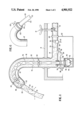
FIG. 1 is a somewhat schematic cross-sectional view through a faucet installation according to the present invention;
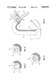
FIG. 2 is an end view of a modified form of faucet nozzle;
FIG. 3 is an end view of a further modified form of faucet nozzle;
FIG. 4 is an end view of another modified form of the faucet nozzle;
FIG. 5 is a top perspective view of still another modified form of the invention; and
FIG. 6 is a view similar to FIG. 5 illustrating yet another modified form of the invention.
Referring now to the drawings wherein like reference characters designate corresponding parts throughout the several views, there is shown in FIG. 1 an inlet 10 connected to a conventional source of hot and cold water. Reference character 12 designates schematically a control means for controlling both water flow and the temperature of the water flowing through the faucet. This may comprise a single handle as employed in ceramic-disk type faucets or a combination hot and cold faucet employing two handles so as to enable the mixing of hot and cold water to obtain any desired temperature according to the position of the handles. Control means 12 extends upwardly through the top wall 14 of a bathroom vanity or the like. It is apparent that the faucet may be mounted in a variety of ways in many different types of environments.
Water passes downstream from the control means through conduit 16 thence upwardly through a spout portion 18 which also extends through wall 14 and is supported thereby. Spout portion terminates in a tapered nozzle 20 having a discharge opening 22. This nozzle provides a stream of water 30 which is substantially non-turbulent as it leaves the discharge opening, and this stream will tend to remain non-turbulent for a substantial distance downstream from the nozzle as it arches downwardly under the influence of gravity as shown. The stream has a substantially homogeneous cross-section into which air bubbles or particulate matter and the like may be introduced to form discontinuities in the stream as hereinafter described.
The outer boundary surface of the stream is of course in contact with the ambient atmosphere, and this surface is substantially smooth and continuous circumferentially of the stream. Circumferentially is intended to denote the dimension extending around the stream which may have a generally circular cross-section or any other cross-section such as in the case of a ribbon-like stream.
A source of light includes a housing 40 having a suitable quartz-halogen lamp 42 surrounded by a reflector 44. A lens 46 is supported by the housing for concentrating the radiated light rays into the lower end 50 of a light guide 52 which comprises a clear transparent rod of polymethyl methacrylate supported within spout portion 18 by spacer elements 54 disposed at spaced intervals along its length. The light is guided within rod 52 by total internal reflection, the index of refraction of polymethyl methacrylate and water being 1.49 and 1.33 respectively. The light guide may be of of various materials and constructions as is well-known in the art. A light guide that is particularly suitable comprises a clear glass rod with a glass cladding having a lower index of refraction than the rod. This eliminates any problems due to staining. The light guide may also be made of glass fibers or synthetic fibers, and may be of a fluid filled construction as is well-known in the art.
The portion of the rod 52 adjacent lower end 50 thereof passes through an opening formed in conduit 16 and is sealed with respect thereto by an O-ring 56. The outer end 58 of rod 5 terminates closely adjacent to the discharge opening 22 so as to introduce light directly into the liquid flowing through the discharge opening and forming the stream, the light being introduced in the direction of liquid flow in the stream in such a manner that a substantial portion and preferably substantially all of the light strikes the outer boundary surface of the stream at an angle of incidence greater than or equal to the critical angle for the media so that the light is guided downstream within the liquid by the phenomenon of total internal reflection of light in the stream.
Light of a certain intensity is introduced directly into the liquid forming the stream at its emergence into ambient atmosphere in such a manner that is initially guided downstream within the liquid of the stream at substantially the same intensity. It is noted that the source of light is hidden from view and the light introduced into the stream is not visible until it exits from the stream in a controlled manner.
Means is provided for automatically turning the light source on and off in accordance with operation of the faucet. A conventional flow switch 60 is provided which is adapted to sense flow of liquid through conduit 16. The flow switch is supported by the conduit and is connected in a suitable electrical circuit (not shown) including leads 62 connecting the flow switch with lamp 42. When the flow switch senses flow of water in conduit 16, the switch is operated to cause the lamp to turn on. When the flow of water ceases, the switch is operated to turn the lamp off. Accordingly, the lamp is turned on only when the faucet is in use.
A conventional air bubble generating means 66 is supported by conduit 16 and is adapted to release air bubbles 70 into the water flowing through the conduit. In order to control the operation of the generating means 66, it is connected in a suitable electrical circuit (not shown) by leads 72, and may also be connected to flow switch 60 so that the bubble generating means is turned on and off along with the lamp by operation of the flow switch.
Bubbles 70 introduced into the water are carried downstream in the water and thence into the stream issuing from nozzle 20. The path of the light rays through rod 52 and into the stream is indicated by the arrows, and it will be noted that some light rays guided inside stream 30 will be deflected by the air bubbles. Some of these deflected light rays strike the outer boundary surface of the stream at an angle of incidence smaller than the critical angle for the media and are thus refracted out of the stream. This light can be seen by an observer, the visual effect being that of colored sparks moving with the stream of water, as hereinafter more fully explained.
A temperature sensing means 80 is supported on conduit 16 and is in communication with the water in the conduit to sense the temperature of the water. The temperature sensing means may be of any conventional construction such as bimetallic means, memory-metal means, fluid-containing systems utilizing coefficient of expansion or electronic devices and the like. This sensing means is connected in a suitable electrical circuit (not shown) including leads 82 connected to an operating means 84 such as a solenoid or the like which is adapted to move a member 86 back and forth in the direction of the arrows in accordance with the temperature of the water.
Member 86 is connected to a frame 88 which moves back and forth along with member 84 and which is shown as carrying a pair of light filters 90 and 92 for varying a particular characteristic of the light which passes therethrough into light guide 52 and thence into the stream of water passing out through the discharge opening of the faucet. These filters may, for example, be red and blue color filters having varying densities thereacross so that light passing therethrough will have varying shades of red and blue depending on the position of the filters. The arrangement is preferably such that when the water is very cold, the color of the light introduced into the stream 30 is a dark blue, and when the water is very hot, the color is bright red. Intermediate shades of blue and red will indicated intermediate temperatures.
It is apparent that the filters may be varied to provide various colors or degrees of intensity of light, and may provide any range of colors, e.g. red-purple; any range of intensities of light, e.g. dim red-bright red; shades of color, e.g. dark red-bright red; shades of white light, e.g. dark-gray-white etc. Other colors such as yellow and green may also be employed. In each case, the color or intensity of the light is varied so as to provide a visual indication of the temperature of the water. Other means may be employed for varying a particular characteristic of the light introduced into stream 30. For example, a lamp may be employed which has varying light characteristics according to the voltage applied thereto, and the applied voltage may be varied according to the temperature of the water.
The color filters may also be mounted within conduit 16 so as to be immersed in the liquid whereby the color filters will be cooled by the liquid. In such a construction, the lower end 50 of the light guide is positioned within the conduit 16, and a window is placed in the wall of the conduit through which light can shine to pass through the filters into the lower end of the light guide.
As mentioned previously, the air bubbles will appear as colored sparks when the light is colored, thereby enabling an observer to determine the temperature of the water by sight at all times.
As an alternative to the provision of an air bubble generator, conventional means may be provided in place of the air bubble generator for introducing particulate matter into the water. Such particulate matter will operate in a manner similar to the air bubbles, deflecting some of the light rays so that some of the deflected rays will be refracted out of the stream.
The source of light and the means for varying a particular characteristic of the light such as the color thereof including the temperature sensing means have been shown as mounted at a location remote from the discharge nozzle of the faucet. Although this arrangement is considered preferable, it should be understood that the source of light and the means for varying a particular characteristic of the light including the temperature sensing means may be mounted within the spout adjacent the discharge opening of the nozzle to introduce light into the stream at the same position as the outer end 58 of rod 52. In such a case, the components may be hydrodynamically formed so as to ensure that the stream 30 has a substantially smooth outer boundary surface, and the components may be mounted on a hollow conduit which would replace rod 54. The electrical connections to the components could extend through such hollow conduit. Furthermore, in this latter case, the color filter may be in direct contact with the liquid; and the color filter may have inherent temperature-dependent characteristics, thereby eliminating the need for a separate temperature sensing means.
Additionally, the air bubble generator or particulate matter dispenser may be located adjacent the discharge opening of the nozzle and hydrodynamically formed so as to ensure that the stream has a substantially smooth outer boundary surface.
The spectacular display is created by controlling the exit of light from the stream. This may be accomplished in a number of ways. The utilization of air bubbles and particulate matter to cause the escape of light from the stream has been described above. It is noted that where the stream is substantially non-turbulent with a substantially smooth outer boundary surface in contact with ambient air and no air bubbles or particulate matter are introduced, the stream may function as a perfect light guide and no light is emitted from the stream. Therefore, no light will be visible until the outer boundary surface is modified as by striking a wash basin which will produce a spectacular release of light.
The display may also be controlled by modifying the outer boundary surface of the stream so that light within the stream will strike certain portions of the outer boundary surface at an angle less than the critical angle. This can be done by selectively creating turbulence in a certain manner to create the desired effect. As seen in FIG. 2, the nozzle may be provided with an inwardly extending projection 100 so that as the stream exits from the discharge opening 22, a narrow strip of turbulence will be created in the outer boundary surface of the stream and extending in the direction of flow of the stream. This strip of turbulence enables light to escape from the stream since the conditions for total internal reflection are not met. The visual effect is a strip of light extending along the stream.
As seen in FIG. 3, a modified nozzle is provided with four equally spaced inwardly extending projections 102 each of which operates in the same manner as projection 100, whereby the visual effect is four strips of light extending along the stream and equally spaced about the circumference of the stream. FIG. 4 illustrates a further modification wherein the discharge opening is provided with a large number of inwardly extending projections 104 so that the discharge opening may be said to have a serrated edge. This construction provides numerous strips of light along the stream, and the entire stream will appear to glisten. It is apparent that various obstructions may be placed in the path of flow of the stream to create turbulence. Such obstructions may be formed integral with the nozzle, or they may be separately supported in position to engage the stream.
Referring now to FIG. 5, means is provided for creating turbulence in the stream in a direction laterally of the direction of flow of the stream. A member 110 such as a wire or the like extends through a slot 112 formed in a housing 114 having mounted therein a suitable electrical device for oscillating the wire back and forth such that it moves laterally through the stream in a direction substantially at a right angle to the direction of flow of the stream. A control means (not shown) may be provided for causing the electrical device to be operated as desired. Housing 114 is connected to a support member 116 which is in turn attached to the outer end of spout portion 18 by strap 118 connected to the support member and extending around the spout portion.
In operation, when member 110 is passed through the stream, turbulence is produced throughout the cross-sectional area of the stream and along a narrow band extending circumferentially around the outer boundary surface of the stream. The visual effect is a band of light moving along the stream at the rate of flow of the stream.
Referring now to FIG. 6, means is provided for modifying the outer boundary surface of the stream by producing vibrations in the liquid medium adjacent the formation of the stream. Spout 18' corresponds to spout 18 of FIG. 5. In tis form of the invention, a housing 120 is supported on the spout adjacent the discharge end thereof by a strap 122. Housing 120 has mounted therein a suitable means for creating vibrations which are coupled into the liquid medium to produce vibrations therein. These vibrations result in an undulating outer boundary surface as indicated by reference character 124. This undulating surface will provide certain areas where the conditions for total internal reflection are not met, and light will exit from the stream as typically indicated by arrows 130.
The means for creating vibrations may comprises a conventional piezoelectric device or conventional means for producing sound waves in the sonic or ultrasonic region. The means for creating vibrations may also be located within the spout if desired.
The frequency of the vibrations may be varied in accordance with the temperature of the liquid medium by connecting the vibrations producing means in a suitable electric circuit (not shown) containing temperature sensing means 80. Thus, the temperature may be determined by the pattern of light emitted from the stream.
The vibrations may also be provided in bursts so that light will be emitted from the stream over a distinct portion of the stream. This portion will move along the stream at the rate of flow of the stream.
The invention has been described with reference to preferred embodiments. Obviously, modifications, alterations and other embodiments will occur to others upon reading and understanding this specification. It is our intention to include all such modifications, alterations and alternate embodiments insofar as they come within the scope of the appended claims or the equivalent thereof.
Claims (36)
1. The method of creating a spectacular display comprising the steps of forming an elongated stream comprising a body of liquid medium having a first index of refraction into a medium which is ambient atmosphere having a second index of refraction lower than the first index of refraction to provide a substantially smooth continuous outer boundary surface enclosing the stream and contacting the ambient atmosphere, introducing light of a certain intensity directly into the body of liquid forming the stream closely adjacent the formation of the stream at its emergence into ambient atmosphere and in the direction of liquid flow in the stream in such a manner that light striking the outer boundary surface at an angle of incidence greater than or equal to the critical angle for the media is initially guided downstream within the liquid at substantially the same intensity by the phenomenon of total internal reflection of light in the stream, and creating a spectacular display by controlling the exit of light from the stream.
2. The method as defined in claim 1 wherein the exit of light is controlled by modifying the outer boundary surface of the stream so that light within the stream will strike certain portions of the outer boundary surface at an angle less than said critical angle.
3. The method as defined in claim 2 wherein the outer boundary surface is modified by the creation of turbulence in the stream.
4. The method as defined in claim 3 wherein the turbulence is created in said outer boundary surface in the direction of flow of the stream.
5. The method as defined in claim 4 wherein the turbulence is created by placing an obstruction in the path of flow of a portion of said outer boundary surface.
6. The method as defined in claim 3 wherein the turbulence is created in said outer boundary surface in a direction laterally of the flow of the stream.
7. The method as defined in claim 6 wherein the turbulence is created by moving a means laterally into the stream to create turbulence.
8. The method as defined in claim 2 wherein the outer boundary surface is modified by providing vibrations in the liquid medium adjacent the formation of the stream to form undulations in said outer boundary surface extending in the direction of liquid flow in the stream.
9. The method as defined in claim 1 wherein the exit of light from the stream is controlled by providing air bubbles in the liquid.
10. The method as defined in claim 1 wherein the exit of light from the stream is controlled by providing particulate matter in the liquid.
11. The method as defined in claim 1 wherein the light is provided at a location remote from the formation of the stream at its emergence into ambient atmosphere, and guiding the light to the, point where it is introduced into the stream.
12. The method as defined in claim 1 including the step of varying the light uniformly throughout the body of liquid in accordance with the temperature of the liquid in the stream to provide a visual perception of the temperature of the liquid.
13. The method as defined in claim 12 including the steps of sensing the temperature of the liquid and automatically varying a characteristic of the light in accordance with the sensed temperature.
14. The method as defined in claim 13 wherein the characteristic of the light which is varied is the color of the light.
15. The method as defined in claim 13 wherein the characteristic of the light which is varied is the intensity of the light.
16. The method as defined in claim 1 including the step of controlling the introduction of light in accordance with flow of liquid.
17. The method as defined in claim 16 including the steps of sensing the flow of liquid and introducing light into the liquid when flow of liquid is sensed.
18. Apparatus for creating a spectacular display comprising means for forming an elongated stream comprising a body of liquid medium having a first index of refraction into a medium which is ambient atmosphere having a second index of refraction lower than the first index of refraction to provide a substantially smooth continuous outer boundary surface enclosing the stream and contacting the ambient atmosphere, means for introducing light of a certain intensity directly into the body of liquid forming the stream closely adjacent the formation of the stream at its emergence into ambient atmosphere and in the direction of liquid flow in the stream in such a manner than light striking the outer boundary surface at an angle of incidence greater than or equal to the critical angle for the media is initially guided downstream within the liquid at substantially the same intensity by the phenomenon of total internal reflection of light in the stream, and means for creating a spectacular display by controlling the exit of light from the stream.
19. The method of creating a spectacular display comprising the steps of forming a solid elongate stream of substantially non-turbulent liquid medium having a first index of refraction into a medium which is ambient atmosphere having a second index of refraction lower than the first index of refraction to provide a substantially smooth outer boundary surface of the stream contacting the ambient atmosphere, introducing light into the liquid forming the stream closely adjacent the formation of the stream at its emergence into ambient atmosphere and in the direction of flow of the stream so that light which enters the stream to strike the outer boundary surface at an angle of incidence greater than or equal to the critical angle for the media is guided downstream within the stream by the phenomenon of total internal reflection of light in the stream, creating a spectacular display by controlling the exit of light from the stream, and varying the light in accordance with the temperature of the liquid in the stream to provide a visual perception of the temperature of the liquid.
20. The method as defined in claim 19 including the steps of sensing the temperature of the liquid and automatically varying a characteristic of the light in accordance with the sensed temperature.
21. The method as defined in claim 20 wherein the characteristic of the light which is varied is the color of the light.
22. The method as defined in claim 20 wherein the characteristic of the light which is varied is the intensity of the light.
23. The method as defined in claim 19 including the step of controlling the introduction of light in accordance with flow of said liquid.
24. The method as defined in claim 19 including the steps of sensing the flow of liquid and introducing light into the liquid when flow of liquid is sensed.
25. The method as defined in claim 19 wherein the exit of light is controlled by modifying the outer boundary surface of the stream so that light within the stream will strike certain portions of the outer boundary surface at an angle less than said critical angle.
26. The method as defined in claim 25 wherein the outer boundary surface is modified by the creation of turbulence in the stream.
27. The method as defined in claim 26 wherein the turbulence is created in said outer boundary surface in the direction of flow of the stream.
28. The method as defined in claim 27 wherein the turbulence is created by placing an obstruction in the path of flow of a portion of said outer boundary surface.
29. The method as defined in claim 26 wherein the turbulence is created in said outer boundary surface in a direction laterally of the flow of the stream.
30. The method as defined in claim 29 wherein the turbulence is created by moving a means laterally into the stream to create turbulence.
31. The method as defined in claim 25 wherein the outer boundary surface is modified by providing vibrations in the liquid medium adjacent the formation of the stream.
32. The method as defined in claim 31 wherein the frequency of said vibrations are varied in accordance with the temperature of the liquid in the stream.
33. The method as defined in claim 19 wherein the exit of light from the stream is controlled by providing air bubbles in the liquid.
34. The method as defined in claim 19 wherein the exit of light from the stream is controlled by providing particulate matter in the liquid.
35. The method as defined in claim 19 wherein light is provided at a location remote from the formation of the stream at its emergence into ambient atmosphere, and guiding the light to the point where it is introduced into the stream.
36. Apparatus for creating a spectacular display comprising means for forming a solid elongate stream of substantially non-turbulent liquid medium having a first index of refraction into a medium which is ambient atmosphere having a second index of refraction lower than the first index of refraction to provide a substantially smooth outer boundary surface of the stream contacting the ambient atmosphere, means for introducing light into the liquid forming the stream closely adjacent the formation of the stream at its emergence into ambient atmosphere and in the direction of flow of the stream so that light which enters the stream to strike the outer boundary surface at an angle of incidence greater than or equal to the critical angle for the media is guided downstream within the stream by the phenomenon of total internal reflection of light in the stream, means for creating a spectacular display by controlling the exit of light from the stream, and means for varying the light in accordance with the temperature of the liquid in the stream to provide a visual perception of the temperature of the liquid.
Applications Claiming Priority (4)
| Application Number | Priority Date | Filing Date | Title |
|---|---|---|---|
| NL8401479A NL8401479A (en) | 1984-05-09 | 1984-05-09 | Lighting effects or illumination from liquid outlet - has light source inside fluid outlet housing or coupled by optical fibres |
| NL8401479 | 1984-05-09 | ||
| AUPG978685 | 1985-03-18 | ||
| AUPG9786 | 1985-03-18 |
Related Parent Applications (1)
| Application Number | Title | Priority Date | Filing Date |
|---|---|---|---|
| US06/822,417 Continuation-In-Part US4749126A (en) | 1984-05-09 | 1985-05-06 | Liquid outlet adapted to provide lighting effects and/or for illumination |
Publications (1)
| Publication Number | Publication Date |
|---|---|
| US4901922A true US4901922A (en) | 1990-02-20 |
Family
ID=25642915
Family Applications (2)
| Application Number | Title | Priority Date | Filing Date |
|---|---|---|---|
| US06/822,417 Expired - Lifetime US4749126A (en) | 1984-05-09 | 1985-05-06 | Liquid outlet adapted to provide lighting effects and/or for illumination |
| US07/200,518 Expired - Lifetime US4901922A (en) | 1984-05-09 | 1988-05-26 | Method and apparatus for creating a spectacular display |
Family Applications Before (1)
| Application Number | Title | Priority Date | Filing Date |
|---|---|---|---|
| US06/822,417 Expired - Lifetime US4749126A (en) | 1984-05-09 | 1985-05-06 | Liquid outlet adapted to provide lighting effects and/or for illumination |
Country Status (6)
| Country | Link |
|---|---|
| US (2) | US4749126A (en) |
| EP (1) | EP0181896B1 (en) |
| JP (1) | JPS61502155A (en) |
| CA (1) | CA1273911A (en) |
| DE (1) | DE3565171D1 (en) |
| WO (1) | WO1985005167A1 (en) |
Cited By (71)
| Publication number | Priority date | Publication date | Assignee | Title |
|---|---|---|---|---|
| US5115973A (en) * | 1988-02-26 | 1992-05-26 | Wet Design | Water displays |
| US5195819A (en) * | 1991-07-11 | 1993-03-23 | 4-D Design, Inc. | Dry spigot lamps |
| US5217292A (en) * | 1991-09-03 | 1993-06-08 | Hydrabaths, Inc. | Whirlpool bath suction assembly having replaceable tub light therein |
| US5222796A (en) * | 1991-07-11 | 1993-06-29 | 4-D Design, Inc. | Dry spigot lamps |
| DE4203107A1 (en) * | 1992-02-04 | 1993-08-05 | Werner Stierle | System for combined light and water display with bulb in lamp housing e.g. for aesthetic display - transmits light emanating with main radiation axis and water guiding housing is positioned in light path in front of lamp housing and has water riser and carrier |
| US5400820A (en) * | 1994-01-24 | 1995-03-28 | Orth; George M. | Light switching apparatus |
| US5452395A (en) * | 1993-10-08 | 1995-09-19 | United States Surgical Corporation | Liquid light guide for endoscopic instrumentation |
| US5491617A (en) * | 1993-05-12 | 1996-02-13 | Currie; Joseph E. | Illuminated fluid tap |
| US5542604A (en) * | 1994-12-07 | 1996-08-06 | The Walt Disney Company | Drinking fountain with sound effects |
| US5608834A (en) * | 1994-10-07 | 1997-03-04 | United States Surgical Corporation | Liquid Light guide |
| US5678617A (en) * | 1995-09-11 | 1997-10-21 | Kuykendal; Robert | Method and apparatus for making a drink hop along a bar or counter |
| US5717807A (en) * | 1995-07-14 | 1998-02-10 | United States Surgical Corporation | Liquid light guide with improved sealing characteristics |
| US5722595A (en) * | 1995-10-30 | 1998-03-03 | Component Hardware Group, Inc. | Grip assembly |
| US5785406A (en) * | 1997-07-16 | 1998-07-28 | Lee; Jen-Wang | Straw with sound/lighting effect producing means |
| US6015216A (en) * | 1997-08-29 | 2000-01-18 | Hirose Co., Ltd. | Fish tank with illuminating light guide device |
| US6030108A (en) * | 1992-08-07 | 2000-02-29 | Bridgestone Corporation | Waterproof lighting apparatus |
| WO2000029125A1 (en) * | 1998-11-17 | 2000-05-25 | Marsh Guy A | Laminar flow nozzle with overhead stream capture |
| US6076741A (en) * | 1997-02-12 | 2000-06-20 | Dandrel; Francois Paul | Device for rendering at least one jet of water luminous |
| US6132056A (en) * | 1998-06-29 | 2000-10-17 | Ruthenberg; Douglas | Apparatus for creating an illuminated waterfall |
| US6257750B1 (en) | 1999-07-09 | 2001-07-10 | Richard T. Strasser | Illuminating fire hose |
| US6375342B1 (en) * | 2000-03-17 | 2002-04-23 | Oasis Waterfalls Llc | Illuminated waterfall |
| US6393192B1 (en) * | 2000-03-17 | 2002-05-21 | Oasis Waterfalls Llc | Illuminated water feature |
| US6416197B1 (en) * | 2001-05-16 | 2002-07-09 | Fu Chang | Fountain water lamp |
| US6484953B2 (en) | 2001-02-06 | 2002-11-26 | Kohler Co. | Water spout with removable laminar flow cartridge |
| US6484952B2 (en) * | 2000-12-20 | 2002-11-26 | Super Vision International, Inc. | Fiber optic illuminated waterfall |
| US20020174577A1 (en) * | 2001-03-14 | 2002-11-28 | Massachusetts Institute Of Technology | Visual display device |
| US6543925B2 (en) * | 2001-03-21 | 2003-04-08 | Robert L. Kuykendal | Multi-colored fountain light |
| US20040200536A1 (en) * | 2003-03-28 | 2004-10-14 | Strasser Richard T. | Fire hose having illuminated sleeve |
| US6805458B2 (en) * | 2002-08-15 | 2004-10-19 | Gelcore Llc | Night light for plumbing fixtures |
| EP1481193A2 (en) * | 2002-02-06 | 2004-12-01 | Kohler Co. | Bathtub chromatherapy system |
| US20050047143A1 (en) * | 2003-09-02 | 2005-03-03 | Currie Joseph Edward | Single light illumination system for a fluid tap |
| WO2005036053A1 (en) * | 2003-10-09 | 2005-04-21 | Paul Kessener | Color-changing fluid illumination device |
| US6886958B1 (en) | 2003-05-19 | 2005-05-03 | O'ryan Industries, Inc. | Optical coupler for use with light-transmissive above-counter sinks |
| US20050155144A1 (en) * | 2004-01-16 | 2005-07-21 | Mcdonald Chris H. | Laminar flow lighted waterfall apparatus for spa |
| US20050276035A1 (en) * | 2004-06-10 | 2005-12-15 | Currie Joseph E | Fluid illumination devices |
| US20060002153A1 (en) * | 2002-10-08 | 2006-01-05 | Currie Robert M | Cordless LED light driving wall module and night light |
| WO2006034757A1 (en) * | 2004-09-28 | 2006-04-06 | Hansa Metallwerke Ag | Sanitary fitting comprising a spray generator |
| US20060077652A1 (en) * | 2004-10-13 | 2006-04-13 | Theus Thomas S | Illuminated plumbing fixtures |
| US20060152917A1 (en) * | 2003-07-17 | 2006-07-13 | Stuhlmacher Glen Ii | Plumbing and lighting fixture |
| US20070291488A1 (en) * | 2006-06-06 | 2007-12-20 | S.C.Johnson & Son, Inc. | Decorative Light System |
| US20070291475A1 (en) * | 2006-06-15 | 2007-12-20 | S.C. Johnson & Son, Inc. | Decorative Light System |
| DE102006037635A1 (en) * | 2006-08-09 | 2008-02-14 | Oase Gmbh | Water jet production device has housing with water inlet opening, jet forming nozzle, illumination equipment and turbulence generator, which is operated in nozzle formed in housing cover |
| US20080164336A1 (en) * | 2005-03-07 | 2008-07-10 | Hansa Metallwerke Ag | Sanitary Fitting With an Illuminated Outlet Consisting of Transparent Material |
| US20080296787A1 (en) * | 2007-06-01 | 2008-12-04 | Wet Enterprises, Inc. | Gas Splattered Fluid Display |
| WO2009104987A1 (en) * | 2008-02-18 | 2009-08-27 | Shtrom Dmitry Yurevich | Lighting device |
| BE1017936A4 (en) * | 2006-11-20 | 2009-12-01 | De Schrijver Frans | Surfing-lights generator for use in e.g. fountain, has multi-filter system that pumps water under certain pressure, where surface tension of water is modified such that light transported along surface of water is partially released |
| US20100033340A1 (en) * | 2007-05-12 | 2010-02-11 | Festo Ag & Co. Kg | Fluid-Technical Assembly Having an Optical Waveguide |
| US20100192865A1 (en) * | 2006-07-20 | 2010-08-05 | Hawk John M | Illuminated Drinking System |
| US20110009809A1 (en) * | 2008-03-20 | 2011-01-13 | Uwe Bielfeldt | Epilation device |
| US20110005619A1 (en) * | 2008-03-27 | 2011-01-13 | Toto Ltd. | Water faucet device |
| US8109301B1 (en) * | 2009-01-06 | 2012-02-07 | Jason Adam Denise | Illuminated refrigerator dispenser system with sensors |
| US20130015203A1 (en) * | 2011-07-13 | 2013-01-17 | Steve Zuloff | Light up liquid projection device and method thereof |
| US8479765B1 (en) * | 2010-07-01 | 2013-07-09 | Timothy Wren | Water faucet assembly |
| US8522372B1 (en) * | 2011-08-10 | 2013-09-03 | Matthew L. Lafon | Illuminated pool fountain system |
| US20140117107A1 (en) * | 2012-10-30 | 2014-05-01 | Custom Molded Products, Inc. | Lighted waterfall device |
| US20140299628A1 (en) * | 2013-04-03 | 2014-10-09 | General Electric Company | Liquid dispensing led nozzle |
| US20150108244A1 (en) * | 2013-10-18 | 2015-04-23 | Bissell Homecare, Inc. | Apparatus for cleaning a surface |
| US9057184B2 (en) | 2011-10-19 | 2015-06-16 | Delta Faucet Company | Insulator base for electronic faucet |
| US9074357B2 (en) | 2011-04-25 | 2015-07-07 | Delta Faucet Company | Mounting bracket for electronic kitchen faucet |
| US9308051B2 (en) | 2011-11-15 | 2016-04-12 | Smiths Medical Asd, Inc. | Illuminated tubing set |
| US9308323B2 (en) | 2011-11-15 | 2016-04-12 | Smiths Medical Asd, Inc. | Systems and methods for illuminated medical tubing detection and management indicating a characteristic of at least one infusion pump |
| US9333698B2 (en) | 2013-03-15 | 2016-05-10 | Delta Faucet Company | Faucet base ring |
| WO2017006168A2 (en) | 2015-07-07 | 2017-01-12 | L.R.A. Kessener Beheer B.V. | Method and device providing a liquid display |
| US20190176048A1 (en) * | 2017-12-08 | 2019-06-13 | SLIS, Inc. | Water toy with illuminated water stream |
| US10393363B2 (en) | 2017-04-25 | 2019-08-27 | Delta Faucet Company | Illumination device for a fluid delivery apparatus |
| WO2019246039A1 (en) * | 2018-06-18 | 2019-12-26 | Spectrum Brands, Inc. | Ultrasonic faucet |
| US10808921B2 (en) * | 2016-05-26 | 2020-10-20 | Spectrum Brands, Inc. | Mountable fixture with sensor activated lighting |
| US11203517B2 (en) * | 2016-06-02 | 2021-12-21 | Marmon Foodservice Technologies, Inc. | Beverage dispensing heads with lighting modules |
| US11458214B2 (en) * | 2015-12-21 | 2022-10-04 | Delta Faucet Company | Fluid delivery system including a disinfectant device |
| US11602032B2 (en) | 2019-12-20 | 2023-03-07 | Kohler Co. | Systems and methods for lighted showering |
| DE102021127212A1 (en) | 2021-10-20 | 2023-04-20 | Neoperl Gmbh | Sanitary functional unit |
Families Citing this family (91)
| Publication number | Priority date | Publication date | Assignee | Title |
|---|---|---|---|---|
| US4749126A (en) * | 1984-05-09 | 1988-06-07 | Kessener H P M | Liquid outlet adapted to provide lighting effects and/or for illumination |
| AT389160B (en) * | 1987-09-24 | 1989-10-25 | Bartenbach Christian | Device for generating screen images (screen pictures) |
| US4955540A (en) * | 1988-02-26 | 1990-09-11 | Wet Enterprises, Inc. | Water displays |
| US5078320A (en) * | 1988-02-26 | 1992-01-07 | Wet Design | Water displays |
| US4936506A (en) * | 1988-11-14 | 1990-06-26 | Ryan James E | Swimming pool fountain |
| DE9109457U1 (en) * | 1991-07-31 | 1991-10-10 | Berenz, Lorenz, 7209 Gosheim, De | |
| US5368228A (en) * | 1993-04-20 | 1994-11-29 | The Walt Disney Company | Method and apparatus for forming a fluid projection screen |
| US5775586A (en) * | 1996-09-19 | 1998-07-07 | Hamilton-Bruzzi; Ginette | Fountain having internally lighted plume |
| US7187141B2 (en) * | 1997-08-26 | 2007-03-06 | Color Kinetics Incorporated | Methods and apparatus for illumination of liquids |
| US6065853A (en) * | 1998-05-19 | 2000-05-23 | Crevier; Kirk D. | Driveway, walkway and landscape lighting |
| US7452092B2 (en) * | 2003-06-25 | 2008-11-18 | Vanderschuit Carl R | Illuminated implements for drinking and/or eating and related methods |
| US6196471B1 (en) * | 1999-11-30 | 2001-03-06 | Douglas Ruthenberg | Apparatus for creating a multi-colored illuminated waterfall or water fountain |
| US6447137B1 (en) | 1999-12-03 | 2002-09-10 | James David Long | Illuminated waterfall lamp |
| DE20021545U1 (en) * | 2000-12-20 | 2001-03-01 | Lin Yung Fa | Illuminating spray device for windshield wipers of motor vehicles |
| US6595675B2 (en) * | 2001-04-23 | 2003-07-22 | Waterway Plastics, Inc. | Pool/spa waterfall unit with fiber optic illumination |
| US6637676B2 (en) * | 2001-04-27 | 2003-10-28 | Interbath, Inc. | Illuminated showerhead |
| IL150914A (en) | 2002-07-25 | 2014-04-30 | Zamir Tribelsky | Method for hydro-optronic photochemical treatment of liquids |
| US6761323B2 (en) * | 2002-08-20 | 2004-07-13 | Johnny Hsieh | Water jet mechanism with composite control light-emitting modules |
| DE10238171A1 (en) | 2002-08-21 | 2004-03-04 | Wörner, Helmut | LED water jet |
| US6857582B1 (en) * | 2002-09-03 | 2005-02-22 | Calvin S. Wang | Vehicle windshield spraying and lighting assembly |
| US7114666B2 (en) | 2002-12-10 | 2006-10-03 | Water Pik, Inc. | Dual massage shower head |
| US7182477B1 (en) * | 2003-06-09 | 2007-02-27 | Hartz Gary E | Illuminators for sprinkler systems |
| US7008073B2 (en) * | 2003-12-22 | 2006-03-07 | Stuhlmacher Ii Glen | Plumbing and lighting fixture |
| DE102004017736B3 (en) * | 2004-01-14 | 2005-09-15 | Saf Armaturen Gmbh | Colored water flow producing method for use in hot water fitting, involves finding temperature range of water by red, blue and green LEDs, where water flowing via LEDs will flow out in respective colors based on found temperature |
| US7387401B2 (en) * | 2004-01-21 | 2008-06-17 | Frank Clark | Showerhead with turbine driven light source |
| CN100336664C (en) * | 2004-03-30 | 2007-09-12 | 三星电子株式会社 | Method for making ink-jet printing head using liquid jet flow to guide laser |
| WO2005100852A1 (en) * | 2004-04-13 | 2005-10-27 | Saf Armaturen Gmbh | Process and device for generating coloured liquid streams in hot-water fittings |
| US7740186B2 (en) | 2004-09-01 | 2010-06-22 | Water Pik, Inc. | Drenching shower head |
| JP2006125060A (en) * | 2004-10-29 | 2006-05-18 | Inax Corp | Stream illuminating device |
| DE102005001305B4 (en) * | 2005-01-05 | 2011-04-14 | Hansa Metallwerke Ag | Sanitary fitting with an arrangement of several light sources |
| DE102005001306A1 (en) * | 2005-01-05 | 2006-07-27 | Hansa Metallwerke Ag | Sanitary fitting with an arrangement of light-emitting elements |
| DE202005005277U1 (en) * | 2005-04-01 | 2006-08-03 | Gentz, Marcus | Lighting device for lighting e.g. water jet of fountain, has carrier body inside water pipe or water hose and illuminant e.g. light emitting diode, where water proof passage way is provided for electrical supply line |
| US7384165B2 (en) * | 2005-07-05 | 2008-06-10 | Kevin Doyle | Water feature with an LED system |
| US20070024456A1 (en) * | 2005-07-26 | 2007-02-01 | Currie Joseph E | Illuminating temperature indicator |
| JP4716814B2 (en) * | 2005-08-09 | 2011-07-06 | 株式会社Inax | Western style flush toilet |
| WO2007124455A2 (en) | 2006-04-20 | 2007-11-01 | Water Pik, Inc. | Converging spray showerhead |
| NL2000212C2 (en) | 2006-09-05 | 2008-03-06 | Ubbink Garden B V | Garden design. |
| US8020787B2 (en) | 2006-11-29 | 2011-09-20 | Water Pik, Inc. | Showerhead system |
| US7789326B2 (en) | 2006-12-29 | 2010-09-07 | Water Pik, Inc. | Handheld showerhead with mode control and method of selecting a handheld showerhead mode |
| US8794543B2 (en) | 2006-12-28 | 2014-08-05 | Water Pik, Inc. | Low-speed pulsating showerhead |
| US8366024B2 (en) | 2006-12-28 | 2013-02-05 | Water Pik, Inc. | Low speed pulsating showerhead |
| US7770822B2 (en) | 2006-12-28 | 2010-08-10 | Water Pik, Inc. | Hand shower with an extendable handle |
| ATE430845T1 (en) | 2007-02-27 | 2009-05-15 | Kwc Ag | SANITARY FITTING WITH ILLUMINATED CONTROL LEVER |
| US8789218B2 (en) | 2007-05-04 | 2014-07-29 | Water Pik, Inc. | Molded arm for showerheads and method of making same |
| NZ582227A (en) * | 2007-07-10 | 2011-09-30 | Astral Pool Australia Pty Ltd | Led illuminated waterfall or fountain apparatus |
| DE202008003087U1 (en) | 2008-03-04 | 2008-08-21 | Butzke, Wolfgang | Device for producing the same color effects when combining liquid streams and translucent catch basins |
| USD624156S1 (en) | 2008-04-30 | 2010-09-21 | Water Pik, Inc. | Pivot ball attachment |
| US8360590B2 (en) * | 2008-08-22 | 2013-01-29 | Kip Carter | Plumbing fixture with light pipe illumination |
| US8348181B2 (en) | 2008-09-15 | 2013-01-08 | Water Pik, Inc. | Shower assembly with radial mode changer |
| USD616061S1 (en) | 2008-09-29 | 2010-05-18 | Water Pik, Inc. | Showerhead assembly |
| DE102009020785A1 (en) * | 2009-05-11 | 2010-11-25 | Marco Systemanalyse Und Entwicklung Gmbh | Valve |
| USD625776S1 (en) | 2009-10-05 | 2010-10-19 | Water Pik, Inc. | Showerhead |
| JP2011153408A (en) * | 2010-01-26 | 2011-08-11 | Lixil Corp | Water supply product |
| TWM399866U (en) * | 2010-08-18 | 2011-03-11 | Ming-Hsiao Lai | Structure for glass and metal film coating composition product |
| US8616470B2 (en) | 2010-08-25 | 2013-12-31 | Water Pik, Inc. | Mode control valve in showerhead connector |
| DK2497577T3 (en) * | 2011-03-10 | 2014-01-27 | Ubbink Garden B V | Apparatus comprising a water reservoir, such as a swimming pool or swimming pool |
| DE102012200486A1 (en) * | 2012-01-13 | 2013-07-18 | Osram Gmbh | Fluorescent device for converting pump light |
| USD678463S1 (en) | 2012-01-27 | 2013-03-19 | Water Pik, Inc. | Ring-shaped wall mount showerhead |
| USD678467S1 (en) | 2012-01-27 | 2013-03-19 | Water Pik, Inc. | Ring-shaped handheld showerhead |
| CA2898716C (en) | 2012-06-22 | 2020-02-11 | Water Pik, Inc. | Bracket for showerhead with integral flow control |
| US20160082485A1 (en) * | 2013-05-20 | 2016-03-24 | Omron Corporation | Washing position confirmation device, fluid delivery position confirmation device, washing position confirmation system, and fluid delivery position confirmation method |
| EP3007829B1 (en) | 2013-06-13 | 2019-02-20 | Water Pik, Inc. | Showerhead with turbine driven shutter |
| DE202013010964U1 (en) * | 2013-12-05 | 2014-02-17 | Simon Schiffmann | Water fitting with integrated contact and contamination protection as well as photocatalytic inner casing disinfection |
| USD744614S1 (en) | 2014-06-13 | 2015-12-01 | Water Pik, Inc. | Wall mount showerhead |
| USD744066S1 (en) | 2014-06-13 | 2015-11-24 | Water Pik, Inc. | Wall mount showerhead |
| USD744064S1 (en) | 2014-06-13 | 2015-11-24 | Water Pik, Inc. | Handheld showerhead |
| USD744065S1 (en) | 2014-06-13 | 2015-11-24 | Water Pik, Inc. | Handheld showerhead |
| USD744611S1 (en) | 2014-06-13 | 2015-12-01 | Water Pik, Inc. | Handheld showerhead |
| USD745111S1 (en) | 2014-06-13 | 2015-12-08 | Water Pik, Inc. | Wall mount showerhead |
| USD744612S1 (en) | 2014-06-13 | 2015-12-01 | Water Pik, Inc. | Handheld showerhead |
| US9884330B2 (en) | 2014-06-20 | 2018-02-06 | Deere & Company | Broadband spray nozzle systems and methods |
| US10189031B2 (en) | 2014-06-20 | 2019-01-29 | Deere & Company | Hybrid flow nozzle and control system |
| US10773271B2 (en) | 2014-06-20 | 2020-09-15 | Deere & Company | Time varying control of the operation of spray systems |
| JP6489765B2 (en) * | 2014-06-24 | 2019-03-27 | 株式会社Lixil | Water discharge device and bathtub device |
| USD766399S1 (en) | 2014-10-03 | 2016-09-13 | Deere & Company | Hybrid spray nozzle turret |
| EP3232873B1 (en) * | 2014-12-15 | 2019-01-30 | Koninklijke Douwe Egberts B.V. | Unit, device and system for preparing beverage consumptions |
| NL2013985B1 (en) | 2014-12-15 | 2016-10-11 | Douwe Egberts Bv | Ceramic valve unit for a beverage machine. |
| NL2013984B1 (en) | 2014-12-15 | 2016-10-11 | Douwe Egberts Bv | Dosing pump device for dosing metered amounts of a liquid product. |
| EP3531008B1 (en) * | 2015-04-08 | 2021-03-31 | Intex Marketing Ltd. | Illuminated water sprayer |
| USD803981S1 (en) | 2016-02-01 | 2017-11-28 | Water Pik, Inc. | Handheld spray nozzle |
| MX2018009276A (en) | 2016-02-01 | 2018-11-09 | Water Pik Inc | Handheld pet spray wand. |
| US10265710B2 (en) | 2016-04-15 | 2019-04-23 | Water Pik, Inc. | Showerhead with dual oscillating massage |
| USD970684S1 (en) | 2016-04-15 | 2022-11-22 | Water Pik, Inc. | Showerhead |
| CN109890512B (en) | 2016-09-08 | 2021-10-15 | 洁碧有限公司 | Pause assembly for showerhead |
| USD843549S1 (en) | 2017-07-19 | 2019-03-19 | Water Pik, Inc. | Handheld spray nozzle |
| US10221583B1 (en) | 2017-10-10 | 2019-03-05 | Water Works Technologies Group, Llc | Artificially-lighted waterfall fixture apparatus and artificial light-focusing module |
| USD872227S1 (en) | 2018-04-20 | 2020-01-07 | Water Pik, Inc. | Handheld spray device |
| JP6480075B1 (en) * | 2018-10-25 | 2019-03-06 | 株式会社Lixil | Water discharge device and bathtub device |
| JP6530127B2 (en) * | 2018-11-29 | 2019-06-12 | 株式会社Lixil | Water discharge device and bathtub device |
| US11603987B2 (en) | 2020-08-31 | 2023-03-14 | Kraus Usa Plumbing Llc | Lighting system for fixtures and appliances |
| CN215843658U (en) * | 2021-07-02 | 2022-02-18 | 厦门市得尔美卫浴有限公司 | Luminous water outlet device, pull-type luminous faucet and luminous spring faucet |
Citations (11)
| Publication number | Priority date | Publication date | Assignee | Title |
|---|---|---|---|---|
| US1553743A (en) * | 1924-07-05 | 1925-09-15 | James V Bluebaugh | Motor meter |
| US1626037A (en) * | 1926-03-17 | 1927-04-26 | Norris B Holt | Display device |
| US1839994A (en) * | 1929-09-04 | 1932-01-05 | Samuel F Moulton | Illuminated fountain |
| US1977997A (en) * | 1931-04-25 | 1934-10-23 | Rca Corp | Control system |
| US2034792A (en) * | 1934-11-12 | 1936-03-24 | Bergman John | Illuminated fountain display |
| US2623367A (en) * | 1950-01-06 | 1952-12-30 | Sunroc Refrigeration Company | Water cooler and filter |
| US2726116A (en) * | 1951-10-20 | 1955-12-06 | John E Barber | Colored fountains |
| US3866832A (en) * | 1973-12-27 | 1975-02-18 | Noguchi Fountain And Plaza Inc | Nozzle assembly for producing an internally illuminated water column |
| GB2099125A (en) * | 1981-05-22 | 1982-12-01 | Filtapac The Co Ltd | Illuminated water fountain |
| FR2562637A1 (en) * | 1984-04-06 | 1985-10-11 | Dandrel Francois | Method and device for making fountains luminous and application of this device |
| US4749126A (en) * | 1984-05-09 | 1988-06-07 | Kessener H P M | Liquid outlet adapted to provide lighting effects and/or for illumination |
Family Cites Families (18)
| Publication number | Priority date | Publication date | Assignee | Title |
|---|---|---|---|---|
| DE41825C (en) * | P. A. günther in Altenburg, S.-A | Innovation in play fountain | ||
| DE401724C (en) * | 1923-03-23 | 1924-09-09 | Joachim Teichmueller Dr | Equipment for illuminating tools and other machines or other workplaces |
| FR593011A (en) * | 1924-12-09 | 1925-08-14 | Process of illumination of a transparent liquid | |
| US1762383A (en) * | 1928-11-19 | 1930-06-10 | Booraem John Francis | Subaqueous illumination of swimming pools |
| FR719705A (en) * | 1931-07-07 | 1932-02-09 | Improvements to luminous fountains | |
| FR1187689A (en) * | 1957-04-30 | 1959-09-15 | Cie D Electricite | New water jet lighting device |
| FR1567059A (en) * | 1967-09-27 | 1969-05-16 | ||
| JPS4814876Y1 (en) * | 1968-11-21 | 1973-04-24 | ||
| JPS4725951A (en) * | 1971-03-25 | 1972-10-23 | ||
| US3702172A (en) * | 1971-09-20 | 1972-11-07 | Dale E Hawkins | Light fountain |
| DE2427182A1 (en) * | 1974-06-05 | 1975-12-18 | Richard Gareis | LAMP BODY WITH ENERGY SUPPLY THROUGH LIGHT GUIDANCE |
| JPS5028756B1 (en) * | 1974-08-15 | 1975-09-18 | ||
| JPS54159075A (en) * | 1978-06-02 | 1979-12-15 | Kurita Water Ind Ltd | Device for waterspout |
| JPS58100304U (en) * | 1981-12-28 | 1983-07-08 | 松下電工株式会社 | fiber optic lighting equipment |
| JPS58184701U (en) * | 1982-06-02 | 1983-12-08 | 東芝エンジニアリング株式会社 | colored fountain device |
| JPS59922A (en) * | 1982-06-25 | 1984-01-06 | Toshiba Corp | Method for detecting compositive deviation in mask rom |
| JPS5949504A (en) * | 1982-09-16 | 1984-03-22 | Toshiba Electric Equip Corp | Illumination device |
| JPS59143201A (en) * | 1983-02-04 | 1984-08-16 | 株式会社 斉美社 | Fountain illuminating method and device therefore |
-
1985
- 1985-05-06 US US06/822,417 patent/US4749126A/en not_active Expired - Lifetime
- 1985-05-06 EP EP85902505A patent/EP0181896B1/en not_active Expired
- 1985-05-06 WO PCT/EP1985/000202 patent/WO1985005167A1/en active IP Right Grant
- 1985-05-06 DE DE8585902505T patent/DE3565171D1/en not_active Expired
- 1985-05-06 JP JP60502239A patent/JPS61502155A/en active Pending
- 1985-06-26 CA CA000485347A patent/CA1273911A/en not_active Expired - Lifetime
-
1988
- 1988-05-26 US US07/200,518 patent/US4901922A/en not_active Expired - Lifetime
Patent Citations (11)
| Publication number | Priority date | Publication date | Assignee | Title |
|---|---|---|---|---|
| US1553743A (en) * | 1924-07-05 | 1925-09-15 | James V Bluebaugh | Motor meter |
| US1626037A (en) * | 1926-03-17 | 1927-04-26 | Norris B Holt | Display device |
| US1839994A (en) * | 1929-09-04 | 1932-01-05 | Samuel F Moulton | Illuminated fountain |
| US1977997A (en) * | 1931-04-25 | 1934-10-23 | Rca Corp | Control system |
| US2034792A (en) * | 1934-11-12 | 1936-03-24 | Bergman John | Illuminated fountain display |
| US2623367A (en) * | 1950-01-06 | 1952-12-30 | Sunroc Refrigeration Company | Water cooler and filter |
| US2726116A (en) * | 1951-10-20 | 1955-12-06 | John E Barber | Colored fountains |
| US3866832A (en) * | 1973-12-27 | 1975-02-18 | Noguchi Fountain And Plaza Inc | Nozzle assembly for producing an internally illuminated water column |
| GB2099125A (en) * | 1981-05-22 | 1982-12-01 | Filtapac The Co Ltd | Illuminated water fountain |
| FR2562637A1 (en) * | 1984-04-06 | 1985-10-11 | Dandrel Francois | Method and device for making fountains luminous and application of this device |
| US4749126A (en) * | 1984-05-09 | 1988-06-07 | Kessener H P M | Liquid outlet adapted to provide lighting effects and/or for illumination |
Cited By (103)
| Publication number | Priority date | Publication date | Assignee | Title |
|---|---|---|---|---|
| US5115973A (en) * | 1988-02-26 | 1992-05-26 | Wet Design | Water displays |
| US5195819A (en) * | 1991-07-11 | 1993-03-23 | 4-D Design, Inc. | Dry spigot lamps |
| US5222796A (en) * | 1991-07-11 | 1993-06-29 | 4-D Design, Inc. | Dry spigot lamps |
| US5217292A (en) * | 1991-09-03 | 1993-06-08 | Hydrabaths, Inc. | Whirlpool bath suction assembly having replaceable tub light therein |
| DE4203107A1 (en) * | 1992-02-04 | 1993-08-05 | Werner Stierle | System for combined light and water display with bulb in lamp housing e.g. for aesthetic display - transmits light emanating with main radiation axis and water guiding housing is positioned in light path in front of lamp housing and has water riser and carrier |
| US6030108A (en) * | 1992-08-07 | 2000-02-29 | Bridgestone Corporation | Waterproof lighting apparatus |
| US5491617A (en) * | 1993-05-12 | 1996-02-13 | Currie; Joseph E. | Illuminated fluid tap |
| US5452395A (en) * | 1993-10-08 | 1995-09-19 | United States Surgical Corporation | Liquid light guide for endoscopic instrumentation |
| US5400820A (en) * | 1994-01-24 | 1995-03-28 | Orth; George M. | Light switching apparatus |
| US5608834A (en) * | 1994-10-07 | 1997-03-04 | United States Surgical Corporation | Liquid Light guide |
| US5542604A (en) * | 1994-12-07 | 1996-08-06 | The Walt Disney Company | Drinking fountain with sound effects |
| US5717807A (en) * | 1995-07-14 | 1998-02-10 | United States Surgical Corporation | Liquid light guide with improved sealing characteristics |
| US5678617A (en) * | 1995-09-11 | 1997-10-21 | Kuykendal; Robert | Method and apparatus for making a drink hop along a bar or counter |
| US5722595A (en) * | 1995-10-30 | 1998-03-03 | Component Hardware Group, Inc. | Grip assembly |
| US6076741A (en) * | 1997-02-12 | 2000-06-20 | Dandrel; Francois Paul | Device for rendering at least one jet of water luminous |
| US5785406A (en) * | 1997-07-16 | 1998-07-28 | Lee; Jen-Wang | Straw with sound/lighting effect producing means |
| US6015216A (en) * | 1997-08-29 | 2000-01-18 | Hirose Co., Ltd. | Fish tank with illuminating light guide device |
| US6132056A (en) * | 1998-06-29 | 2000-10-17 | Ruthenberg; Douglas | Apparatus for creating an illuminated waterfall |
| WO2000029125A1 (en) * | 1998-11-17 | 2000-05-25 | Marsh Guy A | Laminar flow nozzle with overhead stream capture |
| US6085988A (en) * | 1998-11-17 | 2000-07-11 | Marsh; Guy A. | Laminar flow vertical jet stream nozzle with overhead stream capture |
| US6257750B1 (en) | 1999-07-09 | 2001-07-10 | Richard T. Strasser | Illuminating fire hose |
| US6375342B1 (en) * | 2000-03-17 | 2002-04-23 | Oasis Waterfalls Llc | Illuminated waterfall |
| US6393192B1 (en) * | 2000-03-17 | 2002-05-21 | Oasis Waterfalls Llc | Illuminated water feature |
| US6484952B2 (en) * | 2000-12-20 | 2002-11-26 | Super Vision International, Inc. | Fiber optic illuminated waterfall |
| US6484953B2 (en) | 2001-02-06 | 2002-11-26 | Kohler Co. | Water spout with removable laminar flow cartridge |
| US20020174577A1 (en) * | 2001-03-14 | 2002-11-28 | Massachusetts Institute Of Technology | Visual display device |
| US6681508B2 (en) | 2001-03-14 | 2004-01-27 | Massachusetts Institute Of Technology | Visual display device |
| US6543925B2 (en) * | 2001-03-21 | 2003-04-08 | Robert L. Kuykendal | Multi-colored fountain light |
| US6416197B1 (en) * | 2001-05-16 | 2002-07-09 | Fu Chang | Fountain water lamp |
| EP1481193A4 (en) * | 2002-02-06 | 2008-01-23 | Kohler Co | Bathtub chromatherapy system |
| EP1481193A2 (en) * | 2002-02-06 | 2004-12-01 | Kohler Co. | Bathtub chromatherapy system |
| US6805458B2 (en) * | 2002-08-15 | 2004-10-19 | Gelcore Llc | Night light for plumbing fixtures |
| US20060002153A1 (en) * | 2002-10-08 | 2006-01-05 | Currie Robert M | Cordless LED light driving wall module and night light |
| US7114821B2 (en) * | 2002-10-08 | 2006-10-03 | Plastic Inventions And Patents, Inc. | Cordless LED light driving wall module and night light |
| US20040200536A1 (en) * | 2003-03-28 | 2004-10-14 | Strasser Richard T. | Fire hose having illuminated sleeve |
| US6886958B1 (en) | 2003-05-19 | 2005-05-03 | O'ryan Industries, Inc. | Optical coupler for use with light-transmissive above-counter sinks |
| US20050158012A1 (en) * | 2003-05-19 | 2005-07-21 | O'ryan Industries, Inc. | Optical coupler for use with light-transmissive above-counter sinks |
| US6957452B2 (en) | 2003-05-19 | 2005-10-25 | O'ryan Industries, Inc. | Optical coupler for use with light-transmissive above-counter sinks |
| US7434960B2 (en) * | 2003-07-17 | 2008-10-14 | Stuhlmacher Ii Glen | Plumbing and lighting fixture |
| US20060152917A1 (en) * | 2003-07-17 | 2006-07-13 | Stuhlmacher Glen Ii | Plumbing and lighting fixture |
| US20050047143A1 (en) * | 2003-09-02 | 2005-03-03 | Currie Joseph Edward | Single light illumination system for a fluid tap |
| WO2005036053A1 (en) * | 2003-10-09 | 2005-04-21 | Paul Kessener | Color-changing fluid illumination device |
| DE10347615B3 (en) * | 2003-10-09 | 2005-05-25 | Paul Kessener | Fluid lighting device with color change |
| WO2005074431A3 (en) * | 2004-01-16 | 2006-12-28 | Watkins Mfg Corp | Laminar flow lighted waterfall apparatus for spa |
| US7162752B2 (en) * | 2004-01-16 | 2007-01-16 | Watkins Manufacturing Corporation | Laminar flow lighted waterfall apparatus for spa |
| US20070067899A1 (en) * | 2004-01-16 | 2007-03-29 | Mcdonald Chris H | Laminar flow lighted waterfall apparatus for spa |
| US20050155144A1 (en) * | 2004-01-16 | 2005-07-21 | Mcdonald Chris H. | Laminar flow lighted waterfall apparatus for spa |
| AU2004315480B2 (en) * | 2004-01-16 | 2009-09-24 | Watkins Manufacturing Corporation | Laminar flow lighted waterfall apparatus for spa |
| US7472430B2 (en) | 2004-01-16 | 2009-01-06 | Watkins Manufacturing Corporation | Laminar flow lighted waterfall apparatus for spa |
| US20050276035A1 (en) * | 2004-06-10 | 2005-12-15 | Currie Joseph E | Fluid illumination devices |
| WO2006034757A1 (en) * | 2004-09-28 | 2006-04-06 | Hansa Metallwerke Ag | Sanitary fitting comprising a spray generator |
| US20060077652A1 (en) * | 2004-10-13 | 2006-04-13 | Theus Thomas S | Illuminated plumbing fixtures |
| US7303299B2 (en) * | 2004-10-13 | 2007-12-04 | Theus Thomas S | Illuminated plumbing fixtures |
| US7819541B2 (en) * | 2005-03-07 | 2010-10-26 | Hansa Metallwerke Ag | Sanitary fitting with an illuminated outlet consisting of transparent material |
| US20080164336A1 (en) * | 2005-03-07 | 2008-07-10 | Hansa Metallwerke Ag | Sanitary Fitting With an Illuminated Outlet Consisting of Transparent Material |
| US20070291488A1 (en) * | 2006-06-06 | 2007-12-20 | S.C.Johnson & Son, Inc. | Decorative Light System |
| US7410269B2 (en) | 2006-06-06 | 2008-08-12 | S.C. Johnson & Son, Inc. | Decorative light system |
| US20070291475A1 (en) * | 2006-06-15 | 2007-12-20 | S.C. Johnson & Son, Inc. | Decorative Light System |
| US7458698B2 (en) | 2006-06-15 | 2008-12-02 | S.C. Johnson & Son, Inc. | Decorative light system |
| US8578884B2 (en) * | 2006-07-20 | 2013-11-12 | John M Hawk | Illuminated drinking system |
| US20100192865A1 (en) * | 2006-07-20 | 2010-08-05 | Hawk John M | Illuminated Drinking System |
| US20140090603A1 (en) * | 2006-07-20 | 2014-04-03 | Lubing Systems, L.P. | Illuminated drinking system |
| DE102006037635B4 (en) * | 2006-08-09 | 2016-08-04 | Oase Gmbh | Water jet generator |
| DE102006037635A1 (en) * | 2006-08-09 | 2008-02-14 | Oase Gmbh | Water jet production device has housing with water inlet opening, jet forming nozzle, illumination equipment and turbulence generator, which is operated in nozzle formed in housing cover |
| BE1017936A4 (en) * | 2006-11-20 | 2009-12-01 | De Schrijver Frans | Surfing-lights generator for use in e.g. fountain, has multi-filter system that pumps water under certain pressure, where surface tension of water is modified such that light transported along surface of water is partially released |
| US20100033340A1 (en) * | 2007-05-12 | 2010-02-11 | Festo Ag & Co. Kg | Fluid-Technical Assembly Having an Optical Waveguide |
| US20080296787A1 (en) * | 2007-06-01 | 2008-12-04 | Wet Enterprises, Inc. | Gas Splattered Fluid Display |
| US8500038B2 (en) * | 2007-06-01 | 2013-08-06 | Wet Enterprises, Inc. | Gas splattered fluid display |
| WO2009104987A1 (en) * | 2008-02-18 | 2009-08-27 | Shtrom Dmitry Yurevich | Lighting device |
| US20110009809A1 (en) * | 2008-03-20 | 2011-01-13 | Uwe Bielfeldt | Epilation device |
| US20110005619A1 (en) * | 2008-03-27 | 2011-01-13 | Toto Ltd. | Water faucet device |
| US10023456B1 (en) * | 2009-01-06 | 2018-07-17 | Jason Adam Denise | Refrigerator and dispenser |
| US10829361B1 (en) * | 2009-01-06 | 2020-11-10 | Jason Adam Denise | Refrigerator and dispenser |
| US8505593B1 (en) | 2009-01-06 | 2013-08-13 | Jason Adam Denise | Refrigerator and dispenser |
| US9487384B1 (en) | 2009-01-06 | 2016-11-08 | Jason Adam Denise | Refrigerator and dispenser |
| US10046960B1 (en) * | 2009-01-06 | 2018-08-14 | Jason Adam Denise | Refrigerator and dispenser |
| US8109301B1 (en) * | 2009-01-06 | 2012-02-07 | Jason Adam Denise | Illuminated refrigerator dispenser system with sensors |
| US8479765B1 (en) * | 2010-07-01 | 2013-07-09 | Timothy Wren | Water faucet assembly |
| US9074357B2 (en) | 2011-04-25 | 2015-07-07 | Delta Faucet Company | Mounting bracket for electronic kitchen faucet |
| US20130015203A1 (en) * | 2011-07-13 | 2013-01-17 | Steve Zuloff | Light up liquid projection device and method thereof |
| US8622247B2 (en) * | 2011-07-13 | 2014-01-07 | Steve Zuloff | Light up liquid projection device and method thereof |
| US8522372B1 (en) * | 2011-08-10 | 2013-09-03 | Matthew L. Lafon | Illuminated pool fountain system |
| US9057184B2 (en) | 2011-10-19 | 2015-06-16 | Delta Faucet Company | Insulator base for electronic faucet |
| US9308051B2 (en) | 2011-11-15 | 2016-04-12 | Smiths Medical Asd, Inc. | Illuminated tubing set |
| US9308323B2 (en) | 2011-11-15 | 2016-04-12 | Smiths Medical Asd, Inc. | Systems and methods for illuminated medical tubing detection and management indicating a characteristic of at least one infusion pump |
| US20140117107A1 (en) * | 2012-10-30 | 2014-05-01 | Custom Molded Products, Inc. | Lighted waterfall device |
| US9505018B2 (en) * | 2012-10-30 | 2016-11-29 | Custom Molded Products, Inc. | Lighted waterfall device |
| US9333698B2 (en) | 2013-03-15 | 2016-05-10 | Delta Faucet Company | Faucet base ring |
| US9045327B2 (en) * | 2013-04-03 | 2015-06-02 | General Electric Company | Liquid dispensing LED nozzle |
| US20140299628A1 (en) * | 2013-04-03 | 2014-10-09 | General Electric Company | Liquid dispensing led nozzle |
| US20150108244A1 (en) * | 2013-10-18 | 2015-04-23 | Bissell Homecare, Inc. | Apparatus for cleaning a surface |
| US10821459B2 (en) * | 2013-10-18 | 2020-11-03 | Bissell Inc. | Apparatus for cleaning a surface |
| WO2017006168A2 (en) | 2015-07-07 | 2017-01-12 | L.R.A. Kessener Beheer B.V. | Method and device providing a liquid display |
| US11458214B2 (en) * | 2015-12-21 | 2022-10-04 | Delta Faucet Company | Fluid delivery system including a disinfectant device |
| US10808921B2 (en) * | 2016-05-26 | 2020-10-20 | Spectrum Brands, Inc. | Mountable fixture with sensor activated lighting |
| US11203517B2 (en) * | 2016-06-02 | 2021-12-21 | Marmon Foodservice Technologies, Inc. | Beverage dispensing heads with lighting modules |
| US11718516B2 (en) | 2016-06-02 | 2023-08-08 | Marmon Foodservice Technologies, Inc. | Beverage dispensing heads with lighting modules |
| US10697628B2 (en) | 2017-04-25 | 2020-06-30 | Delta Faucet Company | Faucet illumination device |
| US10393363B2 (en) | 2017-04-25 | 2019-08-27 | Delta Faucet Company | Illumination device for a fluid delivery apparatus |
| US20190176048A1 (en) * | 2017-12-08 | 2019-06-13 | SLIS, Inc. | Water toy with illuminated water stream |
| WO2019246039A1 (en) * | 2018-06-18 | 2019-12-26 | Spectrum Brands, Inc. | Ultrasonic faucet |
| US11602032B2 (en) | 2019-12-20 | 2023-03-07 | Kohler Co. | Systems and methods for lighted showering |
| DE102021127212A1 (en) | 2021-10-20 | 2023-04-20 | Neoperl Gmbh | Sanitary functional unit |
Also Published As
| Publication number | Publication date |
|---|---|
| EP0181896B1 (en) | 1988-09-21 |
| CA1273911C (en) | 1990-09-11 |
| JPS61502155A (en) | 1986-09-25 |
| DE3565171D1 (en) | 1988-10-27 |
| EP0181896A1 (en) | 1986-05-28 |
| WO1985005167A1 (en) | 1985-11-21 |
| CA1273911A (en) | 1990-09-11 |
| US4749126A (en) | 1988-06-07 |
Similar Documents
| Publication | Publication Date | Title |
|---|---|---|
| US4901922A (en) | Method and apparatus for creating a spectacular display | |
| AU763858B2 (en) | An apparatus for creating a multi-colored illuminated waterfall or water fountain | |
| US5491617A (en) | Illuminated fluid tap | |
| GB2288974A (en) | Sanitary installations with illuminated water | |
| DE19654359C1 (en) | Water outlet fitting | |
| US6540381B1 (en) | Spectral light tube | |
| US7810942B2 (en) | Sanitary fitting comprising an assembly of several light sources | |
| CA2563527A1 (en) | Process and device for generating coloured liquid streams in hot-water fittings | |
| US20110073670A1 (en) | Laminar flow water jet with wave segmentation, additive, and controller | |
| US4704983A (en) | Flow metering sight glass | |
| BE851399A (en) | FLUID FLOW CONTROL UNIT | |
| DE69003205D1 (en) | Air outlet device with vertical hydrodynamic deflection of an air flow. | |
| NO176153C (en) | Water temperature sensing / flow control mixing valve | |
| JP2928923B2 (en) | Optical transmission method using fountain device and fountain column | |
| ATE14041T1 (en) | BATH AND SHOWER MIXER. | |
| JPH05161564A (en) | Shower apparatus | |
| JPH08152682A (en) | Display device | |
| JPH0393102A (en) | Lighting facility utilizing ripple on water surface | |
| RU2109208C1 (en) | Shining fountain | |
| ATE10260T1 (en) | ADJUSTABLE SHOWER HEAD. | |
| JPS5757216A (en) | Ball circulating type flow-rate sensor | |
| CA2169343C (en) | Illuminated fluid tap | |
| SU1756737A1 (en) | Decorative luminaire | |
| FR2450985A1 (en) | THERMOSTATIC RADIATOR TAP | |
| FR2734620B1 (en) | CARTRIDGE FOR DOMESTIC TAPS WITH THERMOSTAT WITH ONE SINGLE CONTROL FOR TEMPERATURE AND FLOW SETTINGS |
Legal Events
| Date | Code | Title | Description |
|---|---|---|---|
| STCF | Information on status: patent grant |
Free format text: PATENTED CASE |
|
| FPAY | Fee payment |
Year of fee payment: 4 |
|
| FPAY | Fee payment |
Year of fee payment: 8 |
|
| FPAY | Fee payment |
Year of fee payment: 12 |